EP4239722A1 - Negativelektrodenaktivmaterial, herstellungsverfahren dafür und sekundärbatterie damit - Google Patents
Negativelektrodenaktivmaterial, herstellungsverfahren dafür und sekundärbatterie damit Download PDFInfo
- Publication number
- EP4239722A1 EP4239722A1 EP22874235.9A EP22874235A EP4239722A1 EP 4239722 A1 EP4239722 A1 EP 4239722A1 EP 22874235 A EP22874235 A EP 22874235A EP 4239722 A1 EP4239722 A1 EP 4239722A1
- Authority
- EP
- European Patent Office
- Prior art keywords
- negative electrode
- electrode active
- silicon
- active material
- cladding layer
- Prior art date
- Legal status (The legal status is an assumption and is not a legal conclusion. Google has not performed a legal analysis and makes no representation as to the accuracy of the status listed.)
- Pending
Links
- 239000007773 negative electrode material Substances 0.000 title claims abstract description 126
- 238000002360 preparation method Methods 0.000 title claims abstract description 28
- NINIDFKCEFEMDL-UHFFFAOYSA-N Sulfur Chemical group [S] NINIDFKCEFEMDL-UHFFFAOYSA-N 0.000 claims abstract description 152
- 229910052710 silicon Inorganic materials 0.000 claims abstract description 127
- 239000010703 silicon Substances 0.000 claims abstract description 127
- 238000005253 cladding Methods 0.000 claims abstract description 119
- OKTJSMMVPCPJKN-UHFFFAOYSA-N Carbon Chemical group [C] OKTJSMMVPCPJKN-UHFFFAOYSA-N 0.000 claims abstract description 82
- 229910052799 carbon Inorganic materials 0.000 claims abstract description 61
- XUIMIQQOPSSXEZ-UHFFFAOYSA-N Silicon Chemical compound [Si] XUIMIQQOPSSXEZ-UHFFFAOYSA-N 0.000 claims description 125
- 239000011162 core material Substances 0.000 claims description 68
- 239000008151 electrolyte solution Substances 0.000 claims description 52
- SBLRHMKNNHXPHG-UHFFFAOYSA-N 4-fluoro-1,3-dioxolan-2-one Chemical compound FC1COC(=O)O1 SBLRHMKNNHXPHG-UHFFFAOYSA-N 0.000 claims description 47
- VAYTZRYEBVHVLE-UHFFFAOYSA-N 1,3-dioxol-2-one Chemical compound O=C1OC=CO1 VAYTZRYEBVHVLE-UHFFFAOYSA-N 0.000 claims description 46
- 239000000463 material Substances 0.000 claims description 43
- 229910052717 sulfur Inorganic materials 0.000 claims description 28
- 239000011593 sulfur Substances 0.000 claims description 28
- 239000000203 mixture Substances 0.000 claims description 24
- 238000010438 heat treatment Methods 0.000 claims description 20
- 229910045601 alloy Inorganic materials 0.000 claims description 16
- 239000000956 alloy Substances 0.000 claims description 16
- 239000002904 solvent Substances 0.000 claims description 13
- 238000001816 cooling Methods 0.000 claims description 12
- LIVNPJMFVYWSIS-UHFFFAOYSA-N silicon monoxide Chemical class [Si-]#[O+] LIVNPJMFVYWSIS-UHFFFAOYSA-N 0.000 claims description 12
- 238000005245 sintering Methods 0.000 claims description 12
- 239000000243 solution Substances 0.000 claims description 12
- 239000003792 electrolyte Substances 0.000 claims description 11
- 239000002245 particle Substances 0.000 claims description 11
- 239000000843 powder Substances 0.000 claims description 11
- WQZGKKKJIJFFOK-GASJEMHNSA-N Glucose Natural products OC[C@H]1OC(O)[C@H](O)[C@@H](O)[C@@H]1O WQZGKKKJIJFFOK-GASJEMHNSA-N 0.000 claims description 9
- 239000006229 carbon black Substances 0.000 claims description 9
- 239000008103 glucose Substances 0.000 claims description 9
- 229910021389 graphene Inorganic materials 0.000 claims description 9
- 238000002156 mixing Methods 0.000 claims description 9
- 238000003756 stirring Methods 0.000 claims description 9
- 229910000676 Si alloy Inorganic materials 0.000 claims description 8
- 239000002041 carbon nanotube Substances 0.000 claims description 8
- 229910021393 carbon nanotube Inorganic materials 0.000 claims description 8
- 239000006185 dispersion Substances 0.000 claims description 8
- 229910000519 Ferrosilicon Inorganic materials 0.000 claims description 7
- 239000002033 PVDF binder Substances 0.000 claims description 7
- 229920002981 polyvinylidene fluoride Polymers 0.000 claims description 7
- 239000001913 cellulose Substances 0.000 claims description 6
- 229920002678 cellulose Polymers 0.000 claims description 6
- 229910052814 silicon oxide Inorganic materials 0.000 claims description 5
- KXGFMDJXCMQABM-UHFFFAOYSA-N 2-methoxy-6-methylphenol Chemical compound [CH]OC1=CC=CC([CH])=C1O KXGFMDJXCMQABM-UHFFFAOYSA-N 0.000 claims description 4
- 229910000838 Al alloy Inorganic materials 0.000 claims description 4
- 239000004642 Polyimide Substances 0.000 claims description 4
- 229920002472 Starch Polymers 0.000 claims description 4
- CZMRCDWAGMRECN-UGDNZRGBSA-N Sucrose Chemical compound O[C@H]1[C@H](O)[C@@H](CO)O[C@@]1(CO)O[C@@H]1[C@H](O)[C@@H](O)[C@H](O)[C@@H](CO)O1 CZMRCDWAGMRECN-UGDNZRGBSA-N 0.000 claims description 4
- 229930006000 Sucrose Natural products 0.000 claims description 4
- 238000001704 evaporation Methods 0.000 claims description 4
- 239000005011 phenolic resin Substances 0.000 claims description 4
- 229920001568 phenolic resin Polymers 0.000 claims description 4
- 229920002239 polyacrylonitrile Polymers 0.000 claims description 4
- 229920001721 polyimide Polymers 0.000 claims description 4
- 239000008107 starch Substances 0.000 claims description 4
- 235000019698 starch Nutrition 0.000 claims description 4
- 239000005720 sucrose Substances 0.000 claims description 4
- 229910000720 Silicomanganese Inorganic materials 0.000 claims description 3
- 229910000577 Silicon-germanium Inorganic materials 0.000 claims description 3
- 229910000681 Silicon-tin Inorganic materials 0.000 claims description 3
- LEVVHYCKPQWKOP-UHFFFAOYSA-N [Si].[Ge] Chemical compound [Si].[Ge] LEVVHYCKPQWKOP-UHFFFAOYSA-N 0.000 claims description 3
- CSDREXVUYHZDNP-UHFFFAOYSA-N alumanylidynesilicon Chemical compound [Al].[Si] CSDREXVUYHZDNP-UHFFFAOYSA-N 0.000 claims description 3
- 238000001035 drying Methods 0.000 claims description 3
- 239000011261 inert gas Substances 0.000 claims description 3
- LQJIDIOGYJAQMF-UHFFFAOYSA-N lambda2-silanylidenetin Chemical compound [Si].[Sn] LQJIDIOGYJAQMF-UHFFFAOYSA-N 0.000 claims description 3
- 230000002035 prolonged effect Effects 0.000 abstract description 2
- 239000010410 layer Substances 0.000 description 116
- JIBGAHVVIMNRLW-BTVCFUMJSA-N (2r,3s,4r,5r)-2,3,4,5,6-pentahydroxyhexanal;silicon Chemical compound [Si].OC[C@@H](O)[C@@H](O)[C@H](O)[C@@H](O)C=O JIBGAHVVIMNRLW-BTVCFUMJSA-N 0.000 description 39
- 230000000694 effects Effects 0.000 description 36
- 230000001351 cycling effect Effects 0.000 description 33
- 229960005349 sulfur Drugs 0.000 description 24
- 235000001508 sulfur Nutrition 0.000 description 24
- -1 polypropylene Polymers 0.000 description 22
- 239000002131 composite material Substances 0.000 description 17
- 239000000654 additive Substances 0.000 description 15
- 238000000034 method Methods 0.000 description 15
- 229910052744 lithium Inorganic materials 0.000 description 14
- 238000011156 evaluation Methods 0.000 description 13
- WHXSMMKQMYFTQS-UHFFFAOYSA-N Lithium Chemical compound [Li] WHXSMMKQMYFTQS-UHFFFAOYSA-N 0.000 description 12
- 230000000052 comparative effect Effects 0.000 description 10
- WQZGKKKJIJFFOK-VFUOTHLCSA-N beta-D-glucose Chemical compound OC[C@H]1O[C@@H](O)[C@H](O)[C@@H](O)[C@@H]1O WQZGKKKJIJFFOK-VFUOTHLCSA-N 0.000 description 9
- 229960001031 glucose Drugs 0.000 description 9
- 239000005077 polysulfide Substances 0.000 description 9
- 229920001021 polysulfide Polymers 0.000 description 9
- 150000008117 polysulfides Polymers 0.000 description 9
- 230000008569 process Effects 0.000 description 9
- 239000007774 positive electrode material Substances 0.000 description 8
- 229910052751 metal Inorganic materials 0.000 description 7
- 239000002184 metal Substances 0.000 description 7
- 239000004743 Polypropylene Substances 0.000 description 6
- 239000011230 binding agent Substances 0.000 description 6
- 239000006258 conductive agent Substances 0.000 description 6
- 230000001965 increasing effect Effects 0.000 description 6
- 229920001155 polypropylene Polymers 0.000 description 6
- 239000000758 substrate Substances 0.000 description 6
- 239000004698 Polyethylene Substances 0.000 description 5
- 235000010980 cellulose Nutrition 0.000 description 5
- 238000007599 discharging Methods 0.000 description 5
- 239000011888 foil Substances 0.000 description 5
- 238000011065 in-situ storage Methods 0.000 description 5
- 150000002500 ions Chemical class 0.000 description 5
- 238000007344 nucleophilic reaction Methods 0.000 description 5
- 229920001707 polybutylene terephthalate Polymers 0.000 description 5
- 229920000573 polyethylene Polymers 0.000 description 5
- 239000002210 silicon-based material Substances 0.000 description 5
- IJGRMHOSHXDMSA-UHFFFAOYSA-N Atomic nitrogen Chemical compound N#N IJGRMHOSHXDMSA-UHFFFAOYSA-N 0.000 description 4
- PXHVJJICTQNCMI-UHFFFAOYSA-N Nickel Chemical compound [Ni] PXHVJJICTQNCMI-UHFFFAOYSA-N 0.000 description 4
- 229910019142 PO4 Inorganic materials 0.000 description 4
- 239000011267 electrode slurry Substances 0.000 description 4
- 230000006872 improvement Effects 0.000 description 4
- NBIIXXVUZAFLBC-UHFFFAOYSA-K phosphate Chemical compound [O-]P([O-])([O-])=O NBIIXXVUZAFLBC-UHFFFAOYSA-K 0.000 description 4
- 239000010452 phosphate Substances 0.000 description 4
- 229920000139 polyethylene terephthalate Polymers 0.000 description 4
- 239000005020 polyethylene terephthalate Substances 0.000 description 4
- 239000011856 silicon-based particle Substances 0.000 description 4
- 238000003860 storage Methods 0.000 description 4
- OIFBSDVPJOWBCH-UHFFFAOYSA-N Diethyl carbonate Chemical compound CCOC(=O)OCC OIFBSDVPJOWBCH-UHFFFAOYSA-N 0.000 description 3
- XEKOWRVHYACXOJ-UHFFFAOYSA-N Ethyl acetate Chemical compound CCOC(C)=O XEKOWRVHYACXOJ-UHFFFAOYSA-N 0.000 description 3
- KMTRUDSVKNLOMY-UHFFFAOYSA-N Ethylene carbonate Chemical compound O=C1OCCO1 KMTRUDSVKNLOMY-UHFFFAOYSA-N 0.000 description 3
- HBBGRARXTFLTSG-UHFFFAOYSA-N Lithium ion Chemical compound [Li+] HBBGRARXTFLTSG-UHFFFAOYSA-N 0.000 description 3
- MUBZPKHOEPUJKR-UHFFFAOYSA-N Oxalic acid Chemical compound OC(=O)C(O)=O MUBZPKHOEPUJKR-UHFFFAOYSA-N 0.000 description 3
- RTAQQCXQSZGOHL-UHFFFAOYSA-N Titanium Chemical compound [Ti] RTAQQCXQSZGOHL-UHFFFAOYSA-N 0.000 description 3
- 230000000996 additive effect Effects 0.000 description 3
- 238000005054 agglomeration Methods 0.000 description 3
- 230000002776 aggregation Effects 0.000 description 3
- 229910052782 aluminium Inorganic materials 0.000 description 3
- XAGFODPZIPBFFR-UHFFFAOYSA-N aluminium Chemical compound [Al] XAGFODPZIPBFFR-UHFFFAOYSA-N 0.000 description 3
- 230000005540 biological transmission Effects 0.000 description 3
- 230000008859 change Effects 0.000 description 3
- 238000006243 chemical reaction Methods 0.000 description 3
- 239000008367 deionised water Substances 0.000 description 3
- 229910021641 deionized water Inorganic materials 0.000 description 3
- JBTWLSYIZRCDFO-UHFFFAOYSA-N ethyl methyl carbonate Chemical compound CCOC(=O)OC JBTWLSYIZRCDFO-UHFFFAOYSA-N 0.000 description 3
- 239000007789 gas Substances 0.000 description 3
- 229910001416 lithium ion Inorganic materials 0.000 description 3
- 238000004519 manufacturing process Methods 0.000 description 3
- 229920003023 plastic Polymers 0.000 description 3
- 239000004033 plastic Substances 0.000 description 3
- XLYOFNOQVPJJNP-UHFFFAOYSA-N water Chemical compound O XLYOFNOQVPJJNP-UHFFFAOYSA-N 0.000 description 3
- IXPNQXFRVYWDDI-UHFFFAOYSA-N 1-methyl-2,4-dioxo-1,3-diazinane-5-carboximidamide Chemical compound CN1CC(C(N)=N)C(=O)NC1=O IXPNQXFRVYWDDI-UHFFFAOYSA-N 0.000 description 2
- 229910001316 Ag alloy Inorganic materials 0.000 description 2
- BTBUEUYNUDRHOZ-UHFFFAOYSA-N Borate Chemical compound [O-]B([O-])[O-] BTBUEUYNUDRHOZ-UHFFFAOYSA-N 0.000 description 2
- RYGMFSIKBFXOCR-UHFFFAOYSA-N Copper Chemical compound [Cu] RYGMFSIKBFXOCR-UHFFFAOYSA-N 0.000 description 2
- LFQSCWFLJHTTHZ-UHFFFAOYSA-N Ethanol Chemical compound CCO LFQSCWFLJHTTHZ-UHFFFAOYSA-N 0.000 description 2
- 229910001290 LiPF6 Inorganic materials 0.000 description 2
- 229910000990 Ni alloy Inorganic materials 0.000 description 2
- 229920002845 Poly(methacrylic acid) Polymers 0.000 description 2
- 239000004793 Polystyrene Substances 0.000 description 2
- 239000004372 Polyvinyl alcohol Substances 0.000 description 2
- BQCADISMDOOEFD-UHFFFAOYSA-N Silver Chemical compound [Ag] BQCADISMDOOEFD-UHFFFAOYSA-N 0.000 description 2
- 229910001069 Ti alloy Inorganic materials 0.000 description 2
- 239000006230 acetylene black Substances 0.000 description 2
- 239000011149 active material Substances 0.000 description 2
- 239000002134 carbon nanofiber Substances 0.000 description 2
- 239000011248 coating agent Substances 0.000 description 2
- 238000000576 coating method Methods 0.000 description 2
- 150000001875 compounds Chemical class 0.000 description 2
- 230000007423 decrease Effects 0.000 description 2
- 230000002542 deteriorative effect Effects 0.000 description 2
- 238000004146 energy storage Methods 0.000 description 2
- 125000002573 ethenylidene group Chemical group [*]=C=C([H])[H] 0.000 description 2
- FKRCODPIKNYEAC-UHFFFAOYSA-N ethyl propionate Chemical compound CCOC(=O)CC FKRCODPIKNYEAC-UHFFFAOYSA-N 0.000 description 2
- 239000003273 ketjen black Substances 0.000 description 2
- GELKBWJHTRAYNV-UHFFFAOYSA-K lithium iron phosphate Chemical compound [Li+].[Fe+2].[O-]P([O-])([O-])=O GELKBWJHTRAYNV-UHFFFAOYSA-K 0.000 description 2
- 229910021437 lithium-transition metal oxide Inorganic materials 0.000 description 2
- DVATZODUVBMYHN-UHFFFAOYSA-K lithium;iron(2+);manganese(2+);phosphate Chemical compound [Li+].[Mn+2].[Fe+2].[O-]P([O-])([O-])=O DVATZODUVBMYHN-UHFFFAOYSA-K 0.000 description 2
- ILXAVRFGLBYNEJ-UHFFFAOYSA-K lithium;manganese(2+);phosphate Chemical compound [Li+].[Mn+2].[O-]P([O-])([O-])=O ILXAVRFGLBYNEJ-UHFFFAOYSA-K 0.000 description 2
- 230000014759 maintenance of location Effects 0.000 description 2
- 239000007769 metal material Substances 0.000 description 2
- VNWKTOKETHGBQD-UHFFFAOYSA-N methane Chemical compound C VNWKTOKETHGBQD-UHFFFAOYSA-N 0.000 description 2
- TZIHFWKZFHZASV-UHFFFAOYSA-N methyl formate Chemical compound COC=O TZIHFWKZFHZASV-UHFFFAOYSA-N 0.000 description 2
- 229910052759 nickel Inorganic materials 0.000 description 2
- 229910052757 nitrogen Inorganic materials 0.000 description 2
- 239000010450 olivine Substances 0.000 description 2
- 229910052609 olivine Inorganic materials 0.000 description 2
- 239000003960 organic solvent Substances 0.000 description 2
- 238000000643 oven drying Methods 0.000 description 2
- 238000011056 performance test Methods 0.000 description 2
- 229920002401 polyacrylamide Polymers 0.000 description 2
- 229920001343 polytetrafluoroethylene Polymers 0.000 description 2
- 239000004810 polytetrafluoroethylene Substances 0.000 description 2
- 229920002451 polyvinyl alcohol Polymers 0.000 description 2
- 238000003825 pressing Methods 0.000 description 2
- 150000003839 salts Chemical class 0.000 description 2
- 229910052709 silver Inorganic materials 0.000 description 2
- 239000004332 silver Substances 0.000 description 2
- 239000002002 slurry Substances 0.000 description 2
- 239000000661 sodium alginate Substances 0.000 description 2
- 235000010413 sodium alginate Nutrition 0.000 description 2
- 229940005550 sodium alginate Drugs 0.000 description 2
- 238000001694 spray drying Methods 0.000 description 2
- 239000000126 substance Substances 0.000 description 2
- HHVIBTZHLRERCL-UHFFFAOYSA-N sulfonyldimethane Chemical compound CS(C)(=O)=O HHVIBTZHLRERCL-UHFFFAOYSA-N 0.000 description 2
- 229920001897 terpolymer Polymers 0.000 description 2
- 238000012360 testing method Methods 0.000 description 2
- 239000011366 tin-based material Substances 0.000 description 2
- 239000010936 titanium Substances 0.000 description 2
- 229910052719 titanium Inorganic materials 0.000 description 2
- 238000004804 winding Methods 0.000 description 2
- ZZXUZKXVROWEIF-UHFFFAOYSA-N 1,2-butylene carbonate Chemical compound CCC1COC(=O)O1 ZZXUZKXVROWEIF-UHFFFAOYSA-N 0.000 description 1
- HNAGHMKIPMKKBB-UHFFFAOYSA-N 1-benzylpyrrolidine-3-carboxamide Chemical compound C1C(C(=O)N)CCN1CC1=CC=CC=C1 HNAGHMKIPMKKBB-UHFFFAOYSA-N 0.000 description 1
- MBDUIEKYVPVZJH-UHFFFAOYSA-N 1-ethylsulfonylethane Chemical compound CCS(=O)(=O)CC MBDUIEKYVPVZJH-UHFFFAOYSA-N 0.000 description 1
- YBJCDTIWNDBNTM-UHFFFAOYSA-N 1-methylsulfonylethane Chemical compound CCS(C)(=O)=O YBJCDTIWNDBNTM-UHFFFAOYSA-N 0.000 description 1
- UHOPWFKONJYLCF-UHFFFAOYSA-N 2-(2-sulfanylethyl)isoindole-1,3-dione Chemical compound C1=CC=C2C(=O)N(CCS)C(=O)C2=C1 UHOPWFKONJYLCF-UHFFFAOYSA-N 0.000 description 1
- YEJRWHAVMIAJKC-UHFFFAOYSA-N 4-Butyrolactone Chemical compound O=C1CCCO1 YEJRWHAVMIAJKC-UHFFFAOYSA-N 0.000 description 1
- 239000004925 Acrylic resin Substances 0.000 description 1
- 229920001661 Chitosan Polymers 0.000 description 1
- 229910000881 Cu alloy Inorganic materials 0.000 description 1
- YCKRFDGAMUMZLT-UHFFFAOYSA-N Fluorine atom Chemical compound [F] YCKRFDGAMUMZLT-UHFFFAOYSA-N 0.000 description 1
- JGFBQFKZKSSODQ-UHFFFAOYSA-N Isothiocyanatocyclopropane Chemical compound S=C=NC1CC1 JGFBQFKZKSSODQ-UHFFFAOYSA-N 0.000 description 1
- 229910005321 Li15Si4 Inorganic materials 0.000 description 1
- 229910032387 LiCoO2 Inorganic materials 0.000 description 1
- 229910052493 LiFePO4 Inorganic materials 0.000 description 1
- 229910002993 LiMnO2 Inorganic materials 0.000 description 1
- 229910000668 LiMnPO4 Inorganic materials 0.000 description 1
- 229910012619 LiNi0.5Co0.25Mn0.25O2 Inorganic materials 0.000 description 1
- 229910002991 LiNi0.5Co0.2Mn0.3O2 Inorganic materials 0.000 description 1
- 229910011328 LiNi0.6Co0.2Mn0.2O2 Inorganic materials 0.000 description 1
- 229910015717 LiNi0.85Co0.15Al0.05O2 Inorganic materials 0.000 description 1
- 229910015872 LiNi0.8Co0.1Mn0.1O2 Inorganic materials 0.000 description 1
- 229910003005 LiNiO2 Inorganic materials 0.000 description 1
- 229910001228 Li[Ni1/3Co1/3Mn1/3]O2 (NCM 111) Inorganic materials 0.000 description 1
- 229910000572 Lithium Nickel Cobalt Manganese Oxide (NCM) Inorganic materials 0.000 description 1
- 229910002097 Lithium manganese(III,IV) oxide Inorganic materials 0.000 description 1
- RJUFJBKOKNCXHH-UHFFFAOYSA-N Methyl propionate Chemical compound CCC(=O)OC RJUFJBKOKNCXHH-UHFFFAOYSA-N 0.000 description 1
- SECXISVLQFMRJM-UHFFFAOYSA-N N-Methylpyrrolidone Chemical compound CN1CCCC1=O SECXISVLQFMRJM-UHFFFAOYSA-N 0.000 description 1
- XBDQKXXYIPTUBI-UHFFFAOYSA-M Propionate Chemical compound CCC([O-])=O XBDQKXXYIPTUBI-UHFFFAOYSA-M 0.000 description 1
- 229910001128 Sn alloy Inorganic materials 0.000 description 1
- 229920002125 Sokalan® Polymers 0.000 description 1
- 229910000831 Steel Inorganic materials 0.000 description 1
- 238000003917 TEM image Methods 0.000 description 1
- 229920006172 Tetrafluoroethylene propylene Polymers 0.000 description 1
- ATJFFYVFTNAWJD-UHFFFAOYSA-N Tin Chemical compound [Sn] ATJFFYVFTNAWJD-UHFFFAOYSA-N 0.000 description 1
- VIEVWNYBKMKQIH-UHFFFAOYSA-N [Co]=O.[Mn].[Li] Chemical compound [Co]=O.[Mn].[Li] VIEVWNYBKMKQIH-UHFFFAOYSA-N 0.000 description 1
- QTHKJEYUQSLYTH-UHFFFAOYSA-N [Co]=O.[Ni].[Li] Chemical compound [Co]=O.[Ni].[Li] QTHKJEYUQSLYTH-UHFFFAOYSA-N 0.000 description 1
- UMVBXBACMIOFDO-UHFFFAOYSA-N [N].[Si] Chemical compound [N].[Si] UMVBXBACMIOFDO-UHFFFAOYSA-N 0.000 description 1
- FBDMTTNVIIVBKI-UHFFFAOYSA-N [O-2].[Mn+2].[Co+2].[Ni+2].[Li+] Chemical compound [O-2].[Mn+2].[Co+2].[Ni+2].[Li+] FBDMTTNVIIVBKI-UHFFFAOYSA-N 0.000 description 1
- OBNDGIHQAIXEAO-UHFFFAOYSA-N [O].[Si] Chemical compound [O].[Si] OBNDGIHQAIXEAO-UHFFFAOYSA-N 0.000 description 1
- KXKVLQRXCPHEJC-UHFFFAOYSA-N acetic acid trimethyl ester Natural products COC(C)=O KXKVLQRXCPHEJC-UHFFFAOYSA-N 0.000 description 1
- DPXJVFZANSGRMM-UHFFFAOYSA-N acetic acid;2,3,4,5,6-pentahydroxyhexanal;sodium Chemical compound [Na].CC(O)=O.OCC(O)C(O)C(O)C(O)C=O DPXJVFZANSGRMM-UHFFFAOYSA-N 0.000 description 1
- NDPGDHBNXZOBJS-UHFFFAOYSA-N aluminum lithium cobalt(2+) nickel(2+) oxygen(2-) Chemical compound [Li+].[O--].[O--].[O--].[O--].[Al+3].[Co++].[Ni++] NDPGDHBNXZOBJS-UHFFFAOYSA-N 0.000 description 1
- 229910021383 artificial graphite Inorganic materials 0.000 description 1
- 230000000712 assembly Effects 0.000 description 1
- 238000000429 assembly Methods 0.000 description 1
- 229910021418 black silicon Inorganic materials 0.000 description 1
- OBNCKNCVKJNDBV-UHFFFAOYSA-N butanoic acid ethyl ester Natural products CCCC(=O)OCC OBNCKNCVKJNDBV-UHFFFAOYSA-N 0.000 description 1
- PWLNAUNEAKQYLH-UHFFFAOYSA-N butyric acid octyl ester Natural products CCCCCCCCOC(=O)CCC PWLNAUNEAKQYLH-UHFFFAOYSA-N 0.000 description 1
- 239000003575 carbonaceous material Substances 0.000 description 1
- 239000001768 carboxy methyl cellulose Substances 0.000 description 1
- 125000002057 carboxymethyl group Chemical group [H]OC(=O)C([H])([H])[*] 0.000 description 1
- 229940106135 cellulose Drugs 0.000 description 1
- 239000003795 chemical substances by application Substances 0.000 description 1
- 239000000470 constituent Substances 0.000 description 1
- 229920001577 copolymer Polymers 0.000 description 1
- 229910052802 copper Inorganic materials 0.000 description 1
- 239000010949 copper Substances 0.000 description 1
- 239000011889 copper foil Substances 0.000 description 1
- 230000007547 defect Effects 0.000 description 1
- 238000011161 development Methods 0.000 description 1
- 238000010586 diagram Methods 0.000 description 1
- IEJIGPNLZYLLBP-UHFFFAOYSA-N dimethyl carbonate Chemical compound COC(=O)OC IEJIGPNLZYLLBP-UHFFFAOYSA-N 0.000 description 1
- VUPKGFBOKBGHFZ-UHFFFAOYSA-N dipropyl carbonate Chemical compound CCCOC(=O)OCCC VUPKGFBOKBGHFZ-UHFFFAOYSA-N 0.000 description 1
- 238000004090 dissolution Methods 0.000 description 1
- 239000007772 electrode material Substances 0.000 description 1
- 238000005516 engineering process Methods 0.000 description 1
- 230000002708 enhancing effect Effects 0.000 description 1
- 230000007613 environmental effect Effects 0.000 description 1
- 229940093499 ethyl acetate Drugs 0.000 description 1
- CYEDOLFRAIXARV-UHFFFAOYSA-N ethyl propyl carbonate Chemical compound CCCOC(=O)OCC CYEDOLFRAIXARV-UHFFFAOYSA-N 0.000 description 1
- 239000002360 explosive Substances 0.000 description 1
- 239000004744 fabric Substances 0.000 description 1
- 239000011737 fluorine Substances 0.000 description 1
- 229910052731 fluorine Inorganic materials 0.000 description 1
- 239000011521 glass Substances 0.000 description 1
- 239000003365 glass fiber Substances 0.000 description 1
- 229910002804 graphite Inorganic materials 0.000 description 1
- 239000010439 graphite Substances 0.000 description 1
- 229910021385 hard carbon Inorganic materials 0.000 description 1
- 239000007788 liquid Substances 0.000 description 1
- 238000006138 lithiation reaction Methods 0.000 description 1
- 229910003473 lithium bis(trifluoromethanesulfonyl)imide Inorganic materials 0.000 description 1
- 229910000625 lithium cobalt oxide Inorganic materials 0.000 description 1
- 229910002102 lithium manganese oxide Inorganic materials 0.000 description 1
- FRMOHNDAXZZWQI-UHFFFAOYSA-N lithium manganese(2+) nickel(2+) oxygen(2-) Chemical compound [O-2].[Mn+2].[Ni+2].[Li+] FRMOHNDAXZZWQI-UHFFFAOYSA-N 0.000 description 1
- MHCFAGZWMAWTNR-UHFFFAOYSA-M lithium perchlorate Chemical compound [Li+].[O-]Cl(=O)(=O)=O MHCFAGZWMAWTNR-UHFFFAOYSA-M 0.000 description 1
- 229910001486 lithium perchlorate Inorganic materials 0.000 description 1
- 229910001496 lithium tetrafluoroborate Inorganic materials 0.000 description 1
- VDVLPSWVDYJFRW-UHFFFAOYSA-N lithium;bis(fluorosulfonyl)azanide Chemical compound [Li+].FS(=O)(=O)[N-]S(F)(=O)=O VDVLPSWVDYJFRW-UHFFFAOYSA-N 0.000 description 1
- QSZMZKBZAYQGRS-UHFFFAOYSA-N lithium;bis(trifluoromethylsulfonyl)azanide Chemical compound [Li+].FC(F)(F)S(=O)(=O)[N-]S(=O)(=O)C(F)(F)F QSZMZKBZAYQGRS-UHFFFAOYSA-N 0.000 description 1
- IGILRSKEFZLPKG-UHFFFAOYSA-M lithium;difluorophosphinate Chemical compound [Li+].[O-]P(F)(F)=O IGILRSKEFZLPKG-UHFFFAOYSA-M 0.000 description 1
- BFZPBUKRYWOWDV-UHFFFAOYSA-N lithium;oxido(oxo)cobalt Chemical compound [Li+].[O-][Co]=O BFZPBUKRYWOWDV-UHFFFAOYSA-N 0.000 description 1
- VLXXBCXTUVRROQ-UHFFFAOYSA-N lithium;oxido-oxo-(oxomanganiooxy)manganese Chemical compound [Li+].[O-][Mn](=O)O[Mn]=O VLXXBCXTUVRROQ-UHFFFAOYSA-N 0.000 description 1
- URIIGZKXFBNRAU-UHFFFAOYSA-N lithium;oxonickel Chemical compound [Li].[Ni]=O URIIGZKXFBNRAU-UHFFFAOYSA-N 0.000 description 1
- MCVFFRWZNYZUIJ-UHFFFAOYSA-M lithium;trifluoromethanesulfonate Chemical compound [Li+].[O-]S(=O)(=O)C(F)(F)F MCVFFRWZNYZUIJ-UHFFFAOYSA-M 0.000 description 1
- 230000007246 mechanism Effects 0.000 description 1
- 229940017219 methyl propionate Drugs 0.000 description 1
- KKQAVHGECIBFRQ-UHFFFAOYSA-N methyl propyl carbonate Chemical compound CCCOC(=O)OC KKQAVHGECIBFRQ-UHFFFAOYSA-N 0.000 description 1
- 239000011533 mixed conductor Substances 0.000 description 1
- 238000012986 modification Methods 0.000 description 1
- 230000004048 modification Effects 0.000 description 1
- YKYONYBAUNKHLG-UHFFFAOYSA-N n-Propyl acetate Natural products CCCOC(C)=O YKYONYBAUNKHLG-UHFFFAOYSA-N 0.000 description 1
- UUIQMZJEGPQKFD-UHFFFAOYSA-N n-butyric acid methyl ester Natural products CCCC(=O)OC UUIQMZJEGPQKFD-UHFFFAOYSA-N 0.000 description 1
- 239000002071 nanotube Substances 0.000 description 1
- 229910021382 natural graphite Inorganic materials 0.000 description 1
- 230000010355 oscillation Effects 0.000 description 1
- 229920001495 poly(sodium acrylate) polymer Polymers 0.000 description 1
- 229920002961 polybutylene succinate Polymers 0.000 description 1
- 239000004631 polybutylene succinate Substances 0.000 description 1
- 229940090181 propyl acetate Drugs 0.000 description 1
- RUOJZAUFBMNUDX-UHFFFAOYSA-N propylene carbonate Chemical compound CC1COC(=O)O1 RUOJZAUFBMNUDX-UHFFFAOYSA-N 0.000 description 1
- 238000007086 side reaction Methods 0.000 description 1
- 239000002153 silicon-carbon composite material Substances 0.000 description 1
- 239000002356 single layer Substances 0.000 description 1
- 239000011734 sodium Substances 0.000 description 1
- 235000019812 sodium carboxymethyl cellulose Nutrition 0.000 description 1
- 229920001027 sodium carboxymethylcellulose Polymers 0.000 description 1
- NNMHYFLPFNGQFZ-UHFFFAOYSA-M sodium polyacrylate Chemical compound [Na+].[O-]C(=O)C=C NNMHYFLPFNGQFZ-UHFFFAOYSA-M 0.000 description 1
- 229910021384 soft carbon Inorganic materials 0.000 description 1
- 239000007787 solid Substances 0.000 description 1
- 239000010959 steel Substances 0.000 description 1
- 229920003048 styrene butadiene rubber Polymers 0.000 description 1
- HXJUTPCZVOIRIF-UHFFFAOYSA-N sulfolane Chemical compound O=S1(=O)CCCC1 HXJUTPCZVOIRIF-UHFFFAOYSA-N 0.000 description 1
- RBYFNZOIUUXJQD-UHFFFAOYSA-J tetralithium oxalate Chemical compound [Li+].[Li+].[Li+].[Li+].[O-]C(=O)C([O-])=O.[O-]C(=O)C([O-])=O RBYFNZOIUUXJQD-UHFFFAOYSA-J 0.000 description 1
- 239000002562 thickening agent Substances 0.000 description 1
- QHGNHLZPVBIIPX-UHFFFAOYSA-N tin(ii) oxide Chemical compound [Sn]=O QHGNHLZPVBIIPX-UHFFFAOYSA-N 0.000 description 1
- NQPDZGIKBAWPEJ-UHFFFAOYSA-N valeric acid Chemical compound CCCCC(O)=O NQPDZGIKBAWPEJ-UHFFFAOYSA-N 0.000 description 1
Images

Classifications
-
- C—CHEMISTRY; METALLURGY
- C01—INORGANIC CHEMISTRY
- C01B—NON-METALLIC ELEMENTS; COMPOUNDS THEREOF; METALLOIDS OR COMPOUNDS THEREOF NOT COVERED BY SUBCLASS C01C
- C01B17/00—Sulfur; Compounds thereof
-
- C—CHEMISTRY; METALLURGY
- C01—INORGANIC CHEMISTRY
- C01B—NON-METALLIC ELEMENTS; COMPOUNDS THEREOF; METALLOIDS OR COMPOUNDS THEREOF NOT COVERED BY SUBCLASS C01C
- C01B17/00—Sulfur; Compounds thereof
- C01B17/02—Preparation of sulfur; Purification
-
- C—CHEMISTRY; METALLURGY
- C01—INORGANIC CHEMISTRY
- C01B—NON-METALLIC ELEMENTS; COMPOUNDS THEREOF; METALLOIDS OR COMPOUNDS THEREOF NOT COVERED BY SUBCLASS C01C
- C01B32/00—Carbon; Compounds thereof
- C01B32/05—Preparation or purification of carbon not covered by groups C01B32/15, C01B32/20, C01B32/25, C01B32/30
-
- C—CHEMISTRY; METALLURGY
- C01—INORGANIC CHEMISTRY
- C01B—NON-METALLIC ELEMENTS; COMPOUNDS THEREOF; METALLOIDS OR COMPOUNDS THEREOF NOT COVERED BY SUBCLASS C01C
- C01B33/00—Silicon; Compounds thereof
- C01B33/02—Silicon
-
- H—ELECTRICITY
- H01—ELECTRIC ELEMENTS
- H01M—PROCESSES OR MEANS, e.g. BATTERIES, FOR THE DIRECT CONVERSION OF CHEMICAL ENERGY INTO ELECTRICAL ENERGY
- H01M10/00—Secondary cells; Manufacture thereof
- H01M10/05—Accumulators with non-aqueous electrolyte
-
- H—ELECTRICITY
- H01—ELECTRIC ELEMENTS
- H01M—PROCESSES OR MEANS, e.g. BATTERIES, FOR THE DIRECT CONVERSION OF CHEMICAL ENERGY INTO ELECTRICAL ENERGY
- H01M10/00—Secondary cells; Manufacture thereof
- H01M10/05—Accumulators with non-aqueous electrolyte
- H01M10/052—Li-accumulators
- H01M10/0525—Rocking-chair batteries, i.e. batteries with lithium insertion or intercalation in both electrodes; Lithium-ion batteries
-
- H—ELECTRICITY
- H01—ELECTRIC ELEMENTS
- H01M—PROCESSES OR MEANS, e.g. BATTERIES, FOR THE DIRECT CONVERSION OF CHEMICAL ENERGY INTO ELECTRICAL ENERGY
- H01M10/00—Secondary cells; Manufacture thereof
- H01M10/05—Accumulators with non-aqueous electrolyte
- H01M10/056—Accumulators with non-aqueous electrolyte characterised by the materials used as electrolytes, e.g. mixed inorganic/organic electrolytes
- H01M10/0564—Accumulators with non-aqueous electrolyte characterised by the materials used as electrolytes, e.g. mixed inorganic/organic electrolytes the electrolyte being constituted of organic materials only
- H01M10/0566—Liquid materials
- H01M10/0569—Liquid materials characterised by the solvents
-
- H—ELECTRICITY
- H01—ELECTRIC ELEMENTS
- H01M—PROCESSES OR MEANS, e.g. BATTERIES, FOR THE DIRECT CONVERSION OF CHEMICAL ENERGY INTO ELECTRICAL ENERGY
- H01M4/00—Electrodes
- H01M4/02—Electrodes composed of, or comprising, active material
- H01M4/04—Processes of manufacture in general
- H01M4/0471—Processes of manufacture in general involving thermal treatment, e.g. firing, sintering, backing particulate active material, thermal decomposition, pyrolysis
-
- H—ELECTRICITY
- H01—ELECTRIC ELEMENTS
- H01M—PROCESSES OR MEANS, e.g. BATTERIES, FOR THE DIRECT CONVERSION OF CHEMICAL ENERGY INTO ELECTRICAL ENERGY
- H01M4/00—Electrodes
- H01M4/02—Electrodes composed of, or comprising, active material
- H01M4/13—Electrodes for accumulators with non-aqueous electrolyte, e.g. for lithium-accumulators; Processes of manufacture thereof
- H01M4/134—Electrodes based on metals, Si or alloys
-
- H—ELECTRICITY
- H01—ELECTRIC ELEMENTS
- H01M—PROCESSES OR MEANS, e.g. BATTERIES, FOR THE DIRECT CONVERSION OF CHEMICAL ENERGY INTO ELECTRICAL ENERGY
- H01M4/00—Electrodes
- H01M4/02—Electrodes composed of, or comprising, active material
- H01M4/13—Electrodes for accumulators with non-aqueous electrolyte, e.g. for lithium-accumulators; Processes of manufacture thereof
- H01M4/139—Processes of manufacture
- H01M4/1395—Processes of manufacture of electrodes based on metals, Si or alloys
-
- H—ELECTRICITY
- H01—ELECTRIC ELEMENTS
- H01M—PROCESSES OR MEANS, e.g. BATTERIES, FOR THE DIRECT CONVERSION OF CHEMICAL ENERGY INTO ELECTRICAL ENERGY
- H01M4/00—Electrodes
- H01M4/02—Electrodes composed of, or comprising, active material
- H01M4/36—Selection of substances as active materials, active masses, active liquids
- H01M4/362—Composites
- H01M4/366—Composites as layered products
-
- H—ELECTRICITY
- H01—ELECTRIC ELEMENTS
- H01M—PROCESSES OR MEANS, e.g. BATTERIES, FOR THE DIRECT CONVERSION OF CHEMICAL ENERGY INTO ELECTRICAL ENERGY
- H01M4/00—Electrodes
- H01M4/02—Electrodes composed of, or comprising, active material
- H01M4/36—Selection of substances as active materials, active masses, active liquids
- H01M4/38—Selection of substances as active materials, active masses, active liquids of elements or alloys
- H01M4/386—Silicon or alloys based on silicon
-
- H—ELECTRICITY
- H01—ELECTRIC ELEMENTS
- H01M—PROCESSES OR MEANS, e.g. BATTERIES, FOR THE DIRECT CONVERSION OF CHEMICAL ENERGY INTO ELECTRICAL ENERGY
- H01M4/00—Electrodes
- H01M4/02—Electrodes composed of, or comprising, active material
- H01M4/36—Selection of substances as active materials, active masses, active liquids
- H01M4/48—Selection of substances as active materials, active masses, active liquids of inorganic oxides or hydroxides
-
- H—ELECTRICITY
- H01—ELECTRIC ELEMENTS
- H01M—PROCESSES OR MEANS, e.g. BATTERIES, FOR THE DIRECT CONVERSION OF CHEMICAL ENERGY INTO ELECTRICAL ENERGY
- H01M4/00—Electrodes
- H01M4/02—Electrodes composed of, or comprising, active material
- H01M4/36—Selection of substances as active materials, active masses, active liquids
- H01M4/58—Selection of substances as active materials, active masses, active liquids of inorganic compounds other than oxides or hydroxides, e.g. sulfides, selenides, tellurides, halogenides or LiCoFy; of polyanionic structures, e.g. phosphates, silicates or borates
- H01M4/583—Carbonaceous material, e.g. graphite-intercalation compounds or CFx
-
- H—ELECTRICITY
- H01—ELECTRIC ELEMENTS
- H01M—PROCESSES OR MEANS, e.g. BATTERIES, FOR THE DIRECT CONVERSION OF CHEMICAL ENERGY INTO ELECTRICAL ENERGY
- H01M4/00—Electrodes
- H01M4/02—Electrodes composed of, or comprising, active material
- H01M4/62—Selection of inactive substances as ingredients for active masses, e.g. binders, fillers
- H01M4/624—Electric conductive fillers
- H01M4/625—Carbon or graphite
-
- H—ELECTRICITY
- H01—ELECTRIC ELEMENTS
- H01M—PROCESSES OR MEANS, e.g. BATTERIES, FOR THE DIRECT CONVERSION OF CHEMICAL ENERGY INTO ELECTRICAL ENERGY
- H01M4/00—Electrodes
- H01M4/02—Electrodes composed of, or comprising, active material
- H01M2004/026—Electrodes composed of, or comprising, active material characterised by the polarity
- H01M2004/027—Negative electrodes
-
- H—ELECTRICITY
- H01—ELECTRIC ELEMENTS
- H01M—PROCESSES OR MEANS, e.g. BATTERIES, FOR THE DIRECT CONVERSION OF CHEMICAL ENERGY INTO ELECTRICAL ENERGY
- H01M2300/00—Electrolytes
- H01M2300/0017—Non-aqueous electrolytes
- H01M2300/0025—Organic electrolyte
- H01M2300/0028—Organic electrolyte characterised by the solvent
- H01M2300/0034—Fluorinated solvents
-
- H—ELECTRICITY
- H01—ELECTRIC ELEMENTS
- H01M—PROCESSES OR MEANS, e.g. BATTERIES, FOR THE DIRECT CONVERSION OF CHEMICAL ENERGY INTO ELECTRICAL ENERGY
- H01M2300/00—Electrolytes
- H01M2300/0017—Non-aqueous electrolytes
- H01M2300/0025—Organic electrolyte
- H01M2300/0028—Organic electrolyte characterised by the solvent
- H01M2300/0037—Mixture of solvents
-
- H—ELECTRICITY
- H01—ELECTRIC ELEMENTS
- H01M—PROCESSES OR MEANS, e.g. BATTERIES, FOR THE DIRECT CONVERSION OF CHEMICAL ENERGY INTO ELECTRICAL ENERGY
- H01M2300/00—Electrolytes
- H01M2300/0017—Non-aqueous electrolytes
- H01M2300/0048—Molten electrolytes used at high temperature
- H01M2300/0051—Carbonates
-
- Y—GENERAL TAGGING OF NEW TECHNOLOGICAL DEVELOPMENTS; GENERAL TAGGING OF CROSS-SECTIONAL TECHNOLOGIES SPANNING OVER SEVERAL SECTIONS OF THE IPC; TECHNICAL SUBJECTS COVERED BY FORMER USPC CROSS-REFERENCE ART COLLECTIONS [XRACs] AND DIGESTS
- Y02—TECHNOLOGIES OR APPLICATIONS FOR MITIGATION OR ADAPTATION AGAINST CLIMATE CHANGE
- Y02E—REDUCTION OF GREENHOUSE GAS [GHG] EMISSIONS, RELATED TO ENERGY GENERATION, TRANSMISSION OR DISTRIBUTION
- Y02E60/00—Enabling technologies; Technologies with a potential or indirect contribution to GHG emissions mitigation
- Y02E60/10—Energy storage using batteries
Definitions
- the present application relates to the technical field of batteries, and in particular to a negative electrode active material and a preparation method thereof, as well as a secondary battery having the same, and a battery module, a battery pack and an electrical apparatus.
- Secondary batteries have the advantages of reliable working performance, no pollution, memoryless effect, etc., so they are widely used. For example, with the increasing attention to environmental protection issues and the increasing popularity of new energy vehicles, the demand for power secondary batteries will show explosive growth. However, with the increasingly wide application of secondary batteries, the performance of secondary batteries is also facing severe challenges.
- the present application has been made in view of the above-mentioned issues, and an objective thereof is to provide a negative electrode active material and a preparation method thereof, as well a secondary battery having the same, and a battery module, a battery pack and an electrical apparatus, wherein the negative electrode active material can increase the energy density and prolong the cycle life.
- a first aspect of the present application is to provide a negative electrode active material, which comprises: a silicon inner core; a first cladding layer clad on the surface of the silicon inner core, wherein the first cladding layer is a carbon-containing layer; and a second cladding layer clad on the surface of the first cladding layer, wherein the second cladding layer is an elemental sulfur layer.
- the negative electrode active material By disposing a carbon-containing layer as the first cladding layer on the silicon inner core, and further disposing an elemental sulfur layer as the second cladding layer on the first cladding layer, the negative electrode active material thus obtained can increase the energy density and prolong the cycle life.
- the sulfur content in the second cladding layer is 0.1 mass% to 4 mass% based on the total mass of the negative electrode active material.
- the outermost layer of the negative electrode active material is clad with elemental sulfur, and by keeping the elemental sulfur content within this range, the ion-conducting performance is further improved, the interface impedance is reduced, and the cycling performance is improved.
- the carbon content in the first cladding layer is 0.4 mass% to 6 mass% based on the total mass of the negative electrode active material.
- the carbon cladding layer can improve the conductivity of the silicon material, and by keeping the carbon content within the above range, the battery impedance can be further reduced and the cycling performance of the secondary battery can be improved.
- the mass ratio of carbon content to sulfur content is 0.33 to 23 based on the total mass of the negative electrode active material.
- the mass ratio of sulfur content to silicon inner core content is 0.1% to 4.27% based on the total mass of the negative electrode active material.
- the mass ratio of silicon inner core content to carbon content is 15.47 to 246 based on the total mass of the negative electrode active material.
- the silicon inner core is selected from one or more of elemental silicon, silicon alloys, and silicon oxides.
- the silicon alloy is selected from one or more of ferrosilicon alloys, silicon-aluminum alloys, silicomanganese alloys, silicon-tin alloys, and silicon-germanium alloys.
- the carbon source material of the first cladding layer is selected from one or more of glucose, cellulose, sucrose, starch, phenolic resin, polyacrylonitrile, polyimide, polyvinylidene fluoride, carbon black, carbon nanotubes and graphene.
- the second cladding layer has a cladding rate of 70% to 100%.
- the second cladding layer has a thickness of 4 nm to 70 nm
- the first cladding layer has a thickness of 5 nm to 120 nm
- the negative electrode active material has a particle size of 0.5 ⁇ m to 8 ⁇ m.
- a second aspect of the present application provides a preparation method of the negative electrode active material according to the first aspect of the present application, which comprises the following steps (1) to (4) or (a) to (c).
- the steps (1) to (4) are:
- the heating rate in the step (3) is 1°C/min to 5°C/min.
- the heating rate in the step (4) or the step (c) is 1°C/min to 5°C/min.
- the holding time in the step (3) is 3 h to 6 h.
- the holding time in the step (4) or the step (c) is 2.5 h to 7 h.
- a third aspect of the present application is to provide a secondary battery comprising the negative electrode active material according to the first aspect of the present application and an electrolyte solution.
- the electrolyte solution contains fluoroethylene carbonate and/or vinylene carbonate as additives, so as to improve the protection effect on the surface of the negative electrode material and improve the rate and the cycling performance.
- the content of the fluoroethylene carbonate and/or the vinylene carbonate is 0.5 mass% to 13 mass% in terms of mass percentage.
- the mass ratio of the content of the fluoroethylene carbonate to the content of the vinylene carbonate is 0.3 to 5.5.
- the mass ratio of the content of fluoroethylene carbonate and/or vinylene carbonate in the electrolyte solution to the content of elemental sulfur in the negative electrode active material is 0.42 to 60.
- a fourth aspect of the present application provides a battery module comprising the secondary battery according to the third aspect of the present application.
- a fifth aspect of the present application provides a battery pack comprising the battery module according to the fourth aspect of the present application.
- a sixth aspect of the present application provides an electrical apparatus comprising at least one of the secondary battery according to the third aspect of the present application, the battery module according to the fourth aspect of the present application, and the battery pack according to the fifth aspect of the present application.
- the energy density of the secondary battery is improved, and the cycle life is prolonged.
- ranges of lower and upper limits are defined by selecting a lower limit and an upper limit, which define the boundaries of a particular range.
- a range defined in this manner may be inclusive or exclusive of end values, and may be arbitrarily combined, that is, any lower limit may be combined with any upper limit to form a range. For example, if ranges of 60 to 120 and 80 to 110 are listed for a particular parameter, it is understood that ranges of 60 to 110 and 80 to 120 are also expected.
- the minimum range values listed are 1 and 2
- the maximum range values listed are 3, 4 and 5 the following ranges are all expected: 1 to 3, 1 to 4, 1 to 5, 2 to 3, 2 to 4 and 2 to 5.
- a numerical range "a to b" represents an abbreviated representation of any combination of real numbers between a and b, wherein a and b are both real numbers.
- the numerical range "0 to 5" indicates that all real numbers between “0 and 5" have been listed herein, and "0 to 5" is only an abbreviated representation of a combination of these numerical values.
- a certain parameter is an integer of ⁇ 2, it is equivalent to disclosing that the parameter is, for example, an integer of 2, 3, 4, 5, 6, 7, 8, 9, 10, 11, 12, etc.
- the terms “comprise”, “comprising”, “include” and “including” mentioned in the present application may be open-ended or closed-ended.
- the “including” and “comprising” may indicate that it is possible to include or comprise other components not listed, and it is also possible to include or comprise only the listed components.
- the term "or” is inclusive in the present application.
- the phrase “A or B” means “A, B, or both A and B”. More specifically, the condition “A or B” is satisfied by any of the following: A is true (or present) and B is false (or absent); A is false (or absent) and B is true (or present); or both A and B are true (or present).
- the present application provides a negative electrode active material, which comprises: a silicon inner core; a first cladding layer clad on the surface of the silicon inner core, wherein the first cladding layer is a carbon-containing layer; and a second cladding layer clad on the surface of the first cladding layer, wherein the second cladding layer is an elemental sulfur layer.
- the silicon inner core can be alloyed with lithium at room temperature to form Li 15 Si 4 phase, with a theoretical specific capacity of up to 3572 mA h/g, which is much higher than the theoretical specific capacity of commercial graphite (372 mA h/g). Silicon is abundant in reserves in the earth's crust elements (26.4%, ranking second), low in cost and environmentally friendly. Therefore, silicon negative electrode materials have been attracting attention.
- the inventors unexpectedly found that by designing the Si/C/S composite system, the Si inner core is used as the active material to provide lithium storage capacity; the C layer can not only buffer the volume change of Si negative electrode during the charging and discharging process, but also improve the conductivity of Si materials, and avoid the agglomeration of Si particles in the charge-discharge cycle; S element reacts with lithium ions to form polysulfides, which in turn undergo nucleophilic reactions with vinylene carbonate and/or fluoroethylene carbonate in the electrolyte solution to form an artificial SEI film on the surface of silicon particles. Therefore, the negative electrode active material of the Si/C/S composite system combines the advantages of the three, showing high specific capacity and long cycle life.
- the silicon inner core is used as the core
- the carbon-containing layer as the first cladding layer is clad on the outer surface of the silicon inner core
- the elemental sulfur layer as the second cladding layer is further clad on the first cladding layer, thereby obtaining the negative electrode active material with a cladding structure as the Si/C/S composite system.
- the elemental sulfur clad on the outermost surface thereof will react with lithium ions to form polysulfides, and the sulfur in the polysulfides has strong nucleophilicity and will undergo a nucleophilic reaction with vinylene carbonate and/or fluoroethylene carbonate as additives in the electrolyte solution to form an artificial SEI film on the surface of silicon particles in situ to protect the surface of silicon particles and prevent the electrolyte solution from damaging the negative electrode active material, thereby increasing the energy density and prolonging the cycle life.
- TEM transmission electron microscope
- the following steps can be followed: selecting a micro-grid with a certain diameter, clamping the edge of the micro-grid with pointed tweezers, and turning its film side up (the film side is the side that shows gloss when observing under the light), gently laying the micro-grid flat on white filter paper; taking an appropriate amount of the negative electrode active material sample and adding it to a beaker filled with an appropriate amount of ethanol for ultrasonic oscillation; absorbing the sample with a glass capillary, and then adding 2-3 drops of the sample to be tested on the micro-grid; after oven baking, placing the micro-grid with the sample to be tested on a sample stage to test using a transmission electron microscope at a certain magnification, thereby obtaining the transmission electron microscope (TEM) image of the sample to be tested.
- TEM transmission electron microscope
- the sulfur content in the second cladding layer is 0.1 mass% to 4 mass% based on the total mass of the negative electrode active material.
- the elemental sulfur content in the second cladding layer may be within the numerical range formed by any two of the following numerical values as the end values: 0.1 mass%, 0.5 mass%, 1.2 mass%, 2.0 mass%, 3.0 mass%, and 4.0 mass%.
- the outermost layer of the negative electrode active material is clad with elemental sulfur, and by keeping the elemental sulfur content within this range, an artificial SEI film can be formed in situ when the silicon material is intercalated with lithium for the first time, which further improves the ion-conducting performance, reduces the interface impedance, and improves the cycling performance.
- the generated polysulfides will not react completely, and the residual polysulfides will have a shuttle effect, thereby deteriorating the cycling performance of the battery cell; if the elemental sulfur content is too low and outside the above range, the artificial SEI film formed in situ is not dense and firm enough, so the ideal improvement effect can not be achieved.
- the carbon content in the first cladding layer is 0.4 mass% to 6 mass% based on the total mass of the negative electrode active material.
- the elemental carbon content in the first cladding layer may be within the numerical range formed by any two of the following numerical values as the end values: 0.4 mass%, 1.1 mass%, 2.3 mass%, 3.2 mass%, 4.0 mass%, 4.9 mass%, and 6 mass%.
- the carbon cladding layer can improve the conductivity of the silicon material, and by keeping the carbon content within the above range, the battery impedance can be further reduced and the cycling performance of the secondary battery can be improved. If the carbon content is too high and outside the above range, the gram capacity of the negative electrode material will be reduced, affecting the energy density of the battery; if the carbon content is too low and outside the above range, the improvement effect of conductivity and cycling performance will be limited.
- the mass ratio of carbon content to sulfur content is 0.33 to 23 based on the total mass of the negative electrode active material.
- the mass ratio of carbon content to sulfur content can be within the numerical range consisting of any two of the following listed numerical values as the end values: 0.33, 0.58, 0.77, 0.92, 1.15, 1.92, 2.67, 3.33, 4.08, 4.60, 5.00 and 23.
- the mass ratio of sulfur content to silicon inner core content is 0.1% to 4.27% based on the total mass of the negative electrode active material.
- the mass ratio of sulfur content to silicon inner core content can be within the numerical range consisting of any two of the following listed numerical values as the end values: 0.1%, 0.51%, 1.22%, 1.24%, 1.26%, 1.27%, 1.28%, 1.29%, 2.09%, 3.17%, and 4.27%.
- the mass ratio of silicon inner core content to carbon content is 15.47 to 246 based on the total mass of the negative electrode active material.
- the mass ratio of silicon inner core content to carbon content can be within the numerical range consisting of any two of the following listed numerical values as the end values: 15.47, 19.16, 23.70, 29.88, 40.74, 41.17, 41.61, 41.96, 42.26, 42.43, 88.82, and 246.
- the silicon inner core is selected from one or more of elemental silicon, silicon alloys, and silicon oxides, and optionally silicon oxides.
- the silicon alloy is selected from one or more of ferrosilicon alloys, silicon-aluminum alloys, silicomanganese alloys, silicon-tin alloys, and silicon-germanium alloys, and optionally ferrosilicon alloys.
- the silicon inner core material acts as an active material to provide lithium storage capacity. By further setting the silicon inner core material, the effect of improving the cycling performance of the battery can be effectively exerted.
- the carbon source material of the first cladding layer is selected from one or more of glucose, cellulose, sucrose, starch, phenolic resin, polyacrylonitrile, polyimide, polyvinylidene fluoride, carbon black, carbon nanotubes and graphene, and optionally selected from one or more of glucose, cellulose, carbon black, carbon nanotubes and graphene.
- Carbon can not only buffer the volume change of the silicon negative electrode during the charging and discharging process, but also improve the conductivity of the silicon inner core, and also avoid the agglomeration of the silicon inner core in the charge-discharge cycle.
- the carbon source material has a small volume change during the charging and discharging process, and has good cycle stability performance.
- the carbon source material itself is a mixed conductor of ions and electrons.
- carbon and silicon have similar chemical properties, and the two can be closely bonded. Therefore, by further setting the carbon source material, the effect of improving the cycling performance of the battery can be effectively exerted.
- the second cladding layer has a cladding rate of 70% to 100%.
- the cladding rate of the second cladding layer can be within the numerical range consisting of any two of the following listed numerical values as the end values: 70%, 83%, 92%, 98%, and 100%.
- the cladding rate of the second cladding layer refers to the percentage of the coverage area of the second cladding layer on the surface of the first cladding layer to the total surface area of the first cladding layer when the second cladding layer is clad on the surface of the first cladding layer.
- the cladding rate is too low and outside the above range, the artificial SEI film formed in situ is not dense and firm enough, so that the desired improvement effect cannot be achieved.
- the specific range of the cladding rate of the second cladding layer By further setting the specific range of the cladding rate of the second cladding layer, the effect of improving the cycling performance of the battery can be effectively exerted.
- the thickness of the second cladding layer is 4 nm to 70 nm, and in some embodiments, the thickness of the second cladding layer can be within the numerical range consisting of any two of the following listed numerical values as the end values: 4 nm, 10 nm, 23 nm, 32 nm, 47 nm and 70 nm.
- the thickness of the first cladding layer is 5 nm to 120 nm, and in some embodiments, the thickness of the first cladding layer can be within the numerical range consisting of any two of the following listed numerical values as the end values: 5 nm, 10 nm, 12 nm, 22 nm, 25 nm, 30 nm, 50 nm, 78 nm, 98 nm and 120 nm.
- the particle size of the negative electrode active material is 0.5 ⁇ m to 8 ⁇ m, and in some embodiments, the particle size of the negative electrode active material can be within the numerical range consisting of any two of the following listed numerical values as the end values: 0.5 ⁇ m, 1 ⁇ m, 2 ⁇ m, 3 ⁇ m, 4 ⁇ m, 5 ⁇ m, 6 ⁇ m, 7 ⁇ m and 8 ⁇ m.
- the thickness of the second cladding layer, the thickness of the first cladding layer, and the particle size of the negative electrode active material are too large, the lithium ion conduction path will be too long and the kinetics will become poor; if the particle size is too small, the specific surface area of particles will be too large, which will increase side reactions, increase active lithium consumption, and decrease coulombic efficiency.
- the present application proposes a preparation method of a negative electrode active material, which comprises the following steps (1) to (4) or (a) to (c).
- the steps (1) to (4) are:
- the heating rate in the step (3) is 1°C/min to 5°C/min.
- the heating rate in the step (4) or the step (c) is 1°C/min to 5°C/min.
- the holding time in the step (3) is 3 h to 6 h.
- the holding time in the step (4) or the step (c) is 2.5 h to 7 h.
- the above-mentioned negative electrode active material of the present application can be obtained.
- a secondary battery is provided.
- the secondary battery comprises a negative electrode sheet, a positive electrode sheet, an electrolyte, and a separator.
- active ions are intercalated and deintercalated back and forth between the positive electrode sheet and the negative electrode sheet.
- the electrolyte serves to conduct ions between the positive electrode sheet and the negative electrode sheet.
- the separator is provided between the positive electrode sheet and the negative electrode sheet, and mainly functions to prevent a short circuit between the positive electrode and the negative electrode while allowing ions to pass through.
- the negative electrode sheet comprises a negative electrode current collector and a negative electrode film layer provided on at least one surface of the negative electrode current collector, wherein the negative electrode film layer comprises the abovementioned negative electrode active material of the present invention.
- the negative electrode current collector has two opposite surfaces in its own thickness direction, and the negative electrode film layer is provided on either one or both of the two opposite surfaces of the negative electrode current collector.
- the negative electrode current collector can be a metal foil or a composite current collector.
- a copper foil can be used as the metal foil.
- the composite current collector may comprise a high molecular material substrate layer and a metal layer formed on at least one surface of the high molecular material substrate.
- the composite current collector can be formed by forming a metal material (copper, copper alloy, nickel, nickel alloy, titanium, titanium alloy, silver and silver alloy, etc.) on a high molecular material substrate (such as polypropylene (PP), polyethylene terephthalate (PET), polybutylene terephthalate (PBT), polystyrene (PS), polyethylene (PE), and the like).
- PP polypropylene
- PET polyethylene terephthalate
- PBT polybutylene terephthalate
- PS polystyrene
- PE polyethylene
- the negative electrode active material may be a negative electrode active material for batteries well known in the art.
- the negative electrode active material may include at least one of artificial graphite, natural graphite, soft carbon, hard carbon, a silicon-based material, a tin-based material, lithium titanate, and the like.
- the silicon-based material may be selected from at least one of elemental silicon, a silicon-oxygen compound, a silicon-carbon composite, a silicon-nitrogen composite, and a silicon alloy.
- the tin-based material may be selected from at least one of elemental tin, a tin-oxygen compound, and a tin alloy.
- the present application is not limited to these materials, and other conventional materials useful as negative electrode active materials for batteries can also be used. These negative electrode active materials may be used alone or in combination of two or more thereof.
- the negative electrode film layer further optionally comprises a binder.
- the binder may be selected from at least one of styrene butadiene rubber (SBR), polyacrylic acid (PAA), sodium polyacrylate (PAAS), polyacrylamide (PAM), polyvinyl alcohol (PVA), sodium alginate (SA), polymethacrylic acid (PMAA), and carboxymethyl chitosan (CMCS).
- the negative electrode film layer further optionally comprises a conductive agent.
- the conductive agent may be selected from at least one of superconducting carbon, acetylene black, carbon black, Ketjen black, carbon dot, carbon nanotube, graphene, and carbon nanofiber.
- the negative electrode film layer may further optionally comprise other auxiliaries, for example, a thickener (e. g., sodium carboxymethyl cellulose (CMC-Na)) and the like.
- a thickener e. g., sodium carboxymethyl cellulose (CMC-Na)
- CMC-Na sodium carboxymethyl cellulose
- the negative electrode sheet can be prepared by dispersing the components for preparing the negative electrode sheet, for example, the negative electrode active material, the conductive agent, the binder and any other components in a solvent (for example, deionized water) to form a negative electrode slurry; and coating the negative electrode slurry on a negative electrode current collector, followed by oven drying, cold pressing and other procedures, to obtain the negative electrode sheet.
- a solvent for example, deionized water
- the positive electrode sheet comprises a positive electrode current collector and a positive electrode film layer provided on at least one surface of the positive electrode current collector, and the positive electrode film layer comprises the positive electrode active material of the first aspect of the present application.
- the positive electrode current collector has two opposite surfaces in its own thickness direction, and the positive electrode film layer is arranged on either or both of the two opposite surfaces of the positive electrode current collector.
- the positive electrode current collector can be a metal foil or a composite current collector.
- an aluminum foil can be used as the metal foil.
- the composite current collector may include a high molecular material substrate layer and a metal layer formed on at least one surface of the high molecular material substrate layer.
- the composite current collector can be formed by forming a metal material (aluminum, aluminum alloy, nickel, nickel alloy, titanium, titanium alloy, silver and silver alloy, etc.) on a high molecular material substrate (such as polypropylene (PP), polyethylene terephthalate (PET), polybutylene terephthalate (PBT), polystyrene (PS), polyethylene (PE), and the like).
- PP polypropylene
- PET polyethylene terephthalate
- PBT polybutylene terephthalate
- PS polystyrene
- PE polyethylene
- the positive electrode active material may be a positive electrode active material for batteries well known in the art.
- the positive electrode active material may include at least one of the following materials: a lithium-containing phosphate of olivine structure, a lithium transition metal oxide, and a respective modified compound thereof.
- the present application is not limited to these materials, and other conventional materials useful as positive electrode active materials for batteries can also be used. These positive electrode active materials may be used alone or in combination of two or more thereof.
- lithium transition metal oxides may include but are not limited to, at least one of a lithium-cobalt oxide (such as LiCoO 2 ), a lithium-nickel oxide (such as LiNiO 2 ), a lithium-manganese oxide (such as LiMnO 2 and LiMn 2 O 4 ), a lithium-nickel-cobalt oxide, a lithium-manganese-cobalt oxide, a lithium-nickel-manganese oxide, a lithium-nickel-cobalt-manganese oxide (such as LiNi 1/3 Co 1/3 Mn 1/3 O 2 (may also be abbreviated as NCM333), LiNi 0.5 Co 0.2 Mn 0.3 O 2 (may also be abbreviated as NCM523), LiNi 0.5 Co 0.25 Mn 0.25 O 2 (may also be abbreviated as NCM211), LiNi 0.6 Co 0.2 Mn 0.2 O 2 (may also be abbreviated as NCM622), LiNi
- lithium-containing phosphate of olivine structure may include, but are not limited to, at least one of lithium iron phosphate (such as LiFePO 4 (may also be abbreviated as LFP)), a composite material of lithium iron phosphate and carbon, lithium manganese phosphate (such as LiMnPO 4 ), a composite material of lithium manganese phosphate and carbon, lithium iron manganese phosphate, and a composite material of lithium manganese iron phosphate and carbon.
- lithium iron phosphate such as LiFePO 4 (may also be abbreviated as LFP)
- LiMnPO 4 lithium manganese phosphate
- LiMnPO 4 lithium manganese phosphate and carbon
- the positive electrode film layer further optionally comprises a binder.
- the binder may include at least one of polyvinylidene fluoride (PVDF), polytetrafluoroethylene (PTFE), a vinylidene fluoride-tetrafluoroethylene-propylene terpolymer, a vinylidene fluoride-hexafluoropropylene-tetrafluoroethylene terpolymer, a tetrafluoroethylene-hexafluoropropylene copolymer and a fluorine-containing acrylate resin.
- PVDF polyvinylidene fluoride
- PTFE polytetrafluoroethylene
- PTFE polytetrafluoroethylene
- the positive electrode film layer further optionally comprises a conductive agent.
- the conductive agent may include at least one of superconducting carbon, acetylene black, carbon black, Ketjen black, carbon dot, carbon nanotubes, graphene, and carbon nanofibers.
- the positive electrode sheet can be prepared by dispersing the components for preparing the positive electrode sheet, for example, the positive electrode active material, the conductive agent, the binder and any other components in a solvent (for example, N-methyl pyrrolidone) to form a positive electrode slurry; and coating the positive electrode slurry on a positive electrode current collector, followed by oven drying, cold pressing and other procedures, to obtain the positive electrode sheet.
- a solvent for example, N-methyl pyrrolidone
- the electrolyte serves to conduct ions between the positive electrode sheet and the negative electrode sheet.
- the type of the electrolyte is not particularly limited in the present application, and can be selected according to requirements.
- the electrolyte may be in a liquid, gel, or full solid state.
- an electrolyte solution is used as the electrolyte.
- the electrolyte solution comprises an electrolyte salt, a solvent and an additive.
- the electrolyte salt may be selected from at least one of lithium hexafluorophosphate, lithium tetrafluoroborate, lithium perchlorate, lithium hexafluoroarsenate, lithium bis(fluorosulfonyl)imide, lithium bis(trifluoromethanesulfonyl)imide, lithium trifluoromethanesulfonate, lithium difluorophosphate, lithium difluoro(oxalate)borate, lithium bis(oxalate)borate, lithium difluoro bis(oxalate)phosphate, and lithium tetrafluoro(oxalate)phosphate.
- the solvent may be selected from at least one of ethylene carbonate, propylene carbonate, ethyl methyl carbonate, diethyl carbonate, dimethyl carbonate, dipropyl carbonate, methyl propyl carbonate, ethyl propyl carbonate, butylene carbonate, fluoroethylene carbonate, methyl formate, methyl acetate, ethyl acetate, propyl acetate, methyl propionate, ethyl propionate, propyl propionate, methyl butyrate, ethyl butyrate, 1,4-butyrolactone, sulfolane, dimethyl sulfone, ethyl methyl sulfone, and diethyl sulfone.
- the electrolyte solution comprises additives, including fluoroethylene carbonate and/or vinylene carbonate.
- additives including fluoroethylene carbonate and/or vinylene carbonate.
- other additives such as negative electrode film-forming additives, positive electrode film-forming additives can be included, as well as additives that can improve certain properties of the battery, such as additives that improve the overcharge performance of the battery, and additives that improve the high-temperature or low-temperature performance of the battery.
- the electrolyte solution contains fluoroethylene carbonate and/or vinylene carbonate, which can trigger a nucleophilic reaction thereof with polysulfides, thereby generating an artificial SEI film in situ, enhancing the protection on the surface of the negative electrode material and improving the rate and cycling performance.
- fluoroethylene carbonate and vinylene carbonate As additives in the electrolyte solution, it is necessary to add fluoroethylene carbonate and vinylene carbonate, which is conducive to the rapid occurrence of nucleophilic reactions and the complete reaction of polysulfides.
- the content of the fluoroethylene carbonate and/or the vinylene carbonate is 0.5 mass% to 13 mass% in terms of mass percentage, and in some embodiments, the content of the fluoroethylene carbonate and/or the vinylene carbonate can be within the numerical range consisting of any two of the following numerical values as the end values: 0.5 mass%, 0.8 mass%, 1 mass%, 2 mass%, 3 mass%, 4 mass%, 5 mass%, 6 mass%, 7 mass%, 8 mass%, 9 mass%, 10 mass%, 11 mass%, and 13 mass%
- the content of fluoroethylene carbonate and/or vinylene carbonate in the electrolyte solution is set to be within the above range.
- the mass ratio of the content of the fluoroethylene carbonate to the content of the vinylene carbonate (fluoroethylene carbonate content/vinylene carbonate content) in the electrolyte solution is 0.3 to 5.5. In some embodiments, the mass ratio of the content of the fluoroethylene carbonate to the content of the vinylene carbonate can be within the numerical range consisting of any two of the following listed numerical values as the end values: 0.3, 0.5, 1.0, 1.5, 2.0, 2.5, 3.0, 3.5, 4.0, and 5.5.
- the mass ratio of the two is too low and outside the above range, it means that too much vinylene carbonate is added, which is not conducive to the rapid occurrence of nucleophilic reactions and the complete reaction of polysulfides, affecting the ionic conductivity of the electrolyte solution and increasing the impedance of the battery cell; if the mass ratio of the two is too high and outside the above range, it means that the content of fluoroethylene carbonate is too high, which will deteriorate the storage gas production performance of the battery cell, increase the risk of battery cell failure, affect the ionic conductivity of the electrolyte solution, increase the impedance of the battery cell, deteriorate the storage gas production performance of the battery cell and increase the risk of battery cell failure.
- the mass ratio of the content of fluoroethylene carbonate and/or vinylene carbonate in the electrolyte solution to the content of elemental sulfur in the negative electrode active material is 0.42 to 60.
- the mass ratio of the content of fluoroethylene carbonate and/or vinylene carbonate to the content of elemental sulfur in the negative electrode active material can be within the numerical range consisting of any two of the following listed numerical values as the end values: 0.42, 0.67, 0.83, 1.5, 1.67, 2.00, 2.50, 3.00, 3.33, 4.17, 5.00, 5.83, 6.67, 7.50, 8.33, 9.17, 10.83, 12.00, and 60.
- the mass ratio of the content of fluoroethylene carbonate and/or vinylene carbonate in the electrolyte solution to the content of elemental sulfur is set within the above range.
- the secondary battery also comprises a separator.
- the type of the separator is not particularly limited in the present application, and any well-known separator with a porous structure having good chemical stability and mechanical stability may be selected.
- the material of the separator may be selected from at least one of glass fiber, non-woven cloth, polyethylene, polypropylene, and polyvinylidene fluoride.
- the separator may be a single-layer film or a multi-layer composite film, and is not particularly limited. When the separator is a multi-layer composite film, the materials of the layers may be the same or different, which is not particularly limited.
- the positive electrode sheet, the negative electrode sheet, and the separator can be made into an electrode assembly by a winding process or a stacking process.
- the secondary battery may include an outer package.
- the outer package can be used to encapsulate the above-mentioned electrode assembly and electrolyte.
- the outer package of the secondary battery may be a hard case, such as a hard plastic case, an aluminum case, a steel case, and the like.
- the outer package of the secondary battery may also be a soft pack, such as a bag-type soft pack.
- the material of the soft pack may be a plastic, and examples of the plastic include polypropylene, polybutylene terephthalate and polybutylene succinate, etc.
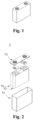
- Fig. 1 shows a secondary battery 5 with a square structure as an example.
- the outer package may comprise a case 51 and a cover plate 53.
- the case 51 can include a bottom plate and a side plate connected to the bottom plate, with the bottom plate and the side plate enclosing to form an accommodating cavity.
- the case 51 has an opening that communicates with the accommodating cavity, and the cover plate 53 may cover the opening to close the accommodating cavity.
- the positive electrode sheet, the negative electrode sheet, and the separator can be formed into an electrode assembly 52 by a winding process or a stacking process.
- the electrode assembly 52 is encapsulated within the accommodating cavity.
- the electrolyte solution impregnates the electrode assembly 52.
- the number of electrode assemblies 52 comprised in the secondary battery 5 may be one or more, which can be selected by those skilled in the art according to specific actual requirements.
- the secondary batteries may be assembled into a battery module, and the number of the secondary batteries included in the battery module may be one or more, and the specific number may be selected by those skilled in the art according to the application and capacity of the battery module.
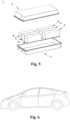
- Fig. 3 shows a battery module 4 as an example.
- a plurality of secondary batteries 5 can be sequentially arranged along the length direction of the battery module 4.
- the plurality of secondary batteries 5 may further be fixed by fasteners.
- the battery module 4 can further include a shell having an accommodating space, in which the plurality of secondary batteries 5 are accommodated.
- the battery module may further be assembled into a battery pack, the number of battery module contained in the battery pack may be one or more, and the specific number can be selected by those skilled in the art according to the use and capacity of the battery pack.
- Figs. 4 and 5 show a battery pack 1 as an example.
- the battery pack 1 may comprise a battery box and a plurality of battery modules 4 provided in the battery box.
- the battery box comprises an upper box 2 and a lower box 3, the upper box 2 can cover the lower box 3 to form a closed space for accommodating the battery modules 4.
- the plurality of battery modules 4 may be arranged in the battery box in any manner.
- the present application further provides an electrical apparatus comprising at least one of the secondary battery, battery module or battery pack provided in the present application.
- the secondary battery, battery module, or battery pack can be used as a power source for the electrical apparatus, and can also be used as an energy storage unit for the electrical apparatus.
- the electrical apparatus may include, but is not limited to, a mobile device (such as a mobile phone, and a laptop, etc.), an electric vehicle (such as an all-electric vehicle, a hybrid electric vehicle, a plug-in hybrid electric vehicle, an electric bicycle, an electric scooter, an electric golf cart, and an electric truck, etc.), an electric train, a ship, a satellite, and an energy storage system, etc.
- the secondary battery, the battery module, or the battery pack may be selected according to its use requirements.
- Fig. 6 is an example of an electrical apparatus.
- the electrical apparatus is an all-electric vehicle, a hybrid electric vehicle, a plug-in hybrid electric vehicle, or the like.
- a battery pack or a battery module may be used.
- the apparatus may be a mobile phone, a tablet, a laptop, etc.
- the apparatus is generally required to be light and thin, and may use a secondary battery as a power source.
- Example 1 the preparation method of the negative electrode active material comprises the following steps (1) to (4), wherein the specific conditions of the steps (1) to (4) are shown in Table 1.
- the electrolyte solution was obtained as follows: mixing ethylene carbonate (EC), ethyl methyl carbonate (EMC), and diethyl carbonate (DEC) at a volume ratio of 3:5:2 to obtain an organic solvent, then dissolving LiPF 6 in the above organic solvent, and adding fluoroethylene carbonate (FEC) and/or vinylene carbonate (VC) as an additive, wherein the specific composition of the electrolyte solution is shown in Table 3, the concentration of LiPF 6 is 1 mol/L, the mass proportion of FEC in the electrolyte solution is 4%, and the mass proportion of VC in the electrolyte solution is 2%.
- EC ethylene carbonate
- EMC ethyl methyl carbonate
- DEC diethyl carbonate
- VC vinylene carbonate
- a metal lithium sheet was used as the counter electrode, a Celgard 2400 separator was used, the electrolyte solution prepared in the above 2 was injected, and they were assembled to obtain a button battery.
- the button battery Under the environment of 25°C and normal pressure, the button battery was discharged to a voltage of 0.005 V at a constant current rate of 0.1 C, then to a voltage of 0.005 V at a constant current rate of 0.05 C, and the specific discharge capacity at this point was recorded, which was the first lithiation capacity; thereafter, it was charged at a constant current rate of 0.1 C until the voltage was 1.5 V, and the specific charge capacity at this point was recorded, which was the first delithiation capacity.
- the button battery was subjected to 50-cycle charge and discharge tests according to the above method, and the delithiation capacity was recorded for each cycle. The results are shown in Table 3.
- the cycling capacity retention rate (%) of the negative electrode active material delithiation capacity of the 50th cycle/delithiation capacity of the first cycle ⁇ 100%.
- Example 2 6 to 44, and Comparative Examples 1 and 2 the same preparation method as Example 1 was adopted, except for the changes in the specific conditions in the steps (1) to (4) as shown in Table 1, thus providing negative electrode active materials.
- the electrolyte solution was obtained by the same preparation method as in Example 1, and the specific composition of the electrolyte solution is shown in Table 3.
- Example 3 The same evaluation method as in Example 1 was used for performance evaluation, and the evaluation results are shown in Table 3.
- Example 3 the preparation method of the negative electrode active material comprises the following steps (a) to (c), wherein the specific conditions of the steps (a) to (c) are shown in Table 2.
- the electrolyte solution was obtained by the same preparation method as in Example 1, and the specific composition of the electrolyte solution is shown in Table 3.
- Example 3 The same evaluation method as in Example 1 was used for performance evaluation, and the evaluation results are shown in Table 3.
- Example 4 the same preparation method as Example 3 was adopted, except for the changes in the specific conditions in the steps (a) to (c) as shown in Table 2, thus providing negative electrode active materials.
- the electrolyte solution was obtained by the same preparation method as in Example 1, and the specific composition of the electrolyte solution is shown in Table 3.
- the preparation method of the negative electrode active material comprises the following steps (1) to (4) Step (1): Step (2): Step (3): Step (4): Carbon source material Silicon inner core material Heatin g rate (°C/mi n) Holdin g temper ature (°C) Holdin g time (h) Eleme ntal sulfur materi al Heatin g rate (°C/mi n) Holdin g temper ature (°C) Holdin g time (h)
- Example 1 Glucose Ferrosili con alloy 1°C/m in 900°C 4h Eleme ntal sulfur 1°C/m in 300°C 4h
- Example 2 Glucose Element al silicon 5°C/m in 1100° C 6h Eleme ntal sulfur 5°C/m in 350°C 7h
- Example 6 Cellulose Silicon monoxi de 1°C/m in 700°C 3h Eleme ntal sulfur 1°C/m in 200°C 2.5
- the silicon inner core is selected from one or more of elemental silicon, silicon alloys and silicon oxides, which can achieve the effect of improving the energy density of the secondary battery and prolonging the cycle life.
- the carbon source material as the first cladding layer is selected from one or more of glucose, sucrose, starch, phenolic resin, polyacrylonitrile, polyimide, polyvinylidene fluoride, carbon black, carbon nanotubes and graphene, which can achieve the effect of improving the energy density of the secondary battery and prolonging the cycle life.
- the carbon content in the negative electrode active material is further set within a specific range, and the thickness of the first cladding layer is correspondingly set within a specific range, which can achieve the effect of improving the energy density of the secondary battery and prolonging the cycle life.
- the sulfur content in the negative electrode active material is further set within a specific range, and the thickness of the second cladding layer is correspondingly set within a specific range, which can achieve the effect of improving the energy density of the secondary battery and prolonging the cycle life.
- the particle size of the negative electrode active material is further set within a specific range, which can achieve the effect of improving the energy density of the secondary battery and prolonging the cycle life.
- the content of fluoroethylene carbonate as a specific additive in the electrolyte solution is further set within a specific range, which can achieve the effect of improving the energy density of the secondary battery and prolonging the cycle life.
Landscapes
- Chemical & Material Sciences (AREA)
- Chemical Kinetics & Catalysis (AREA)
- Electrochemistry (AREA)
- General Chemical & Material Sciences (AREA)
- Engineering & Computer Science (AREA)
- Inorganic Chemistry (AREA)
- Organic Chemistry (AREA)
- Manufacturing & Machinery (AREA)
- Composite Materials (AREA)
- Materials Engineering (AREA)
- General Physics & Mathematics (AREA)
- Condensed Matter Physics & Semiconductors (AREA)
- Physics & Mathematics (AREA)
- Battery Electrode And Active Subsutance (AREA)
- Secondary Cells (AREA)
Applications Claiming Priority (2)
| Application Number | Priority Date | Filing Date | Title |
|---|---|---|---|
| CN202111143669.2A CN115842108A (zh) | 2021-09-28 | 2021-09-28 | 负极活性材料及其制备方法、具备其的二次电池 |
| PCT/CN2022/094760 WO2023050837A1 (zh) | 2021-09-28 | 2022-05-24 | 负极活性材料及其制备方法、具备其的二次电池 |
Publications (2)
| Publication Number | Publication Date |
|---|---|
| EP4239722A1 true EP4239722A1 (de) | 2023-09-06 |
| EP4239722A4 EP4239722A4 (de) | 2025-02-26 |
Family
ID=85575091
Family Applications (1)
| Application Number | Title | Priority Date | Filing Date |
|---|---|---|---|
| EP22874235.9A Pending EP4239722A4 (de) | 2021-09-28 | 2022-05-24 | Negativelektrodenaktivmaterial, herstellungsverfahren dafür und sekundärbatterie damit |
Country Status (6)
| Country | Link |
|---|---|
| US (1) | US20230420661A1 (de) |
| EP (1) | EP4239722A4 (de) |
| JP (1) | JP7698045B2 (de) |
| KR (1) | KR20230088792A (de) |
| CN (1) | CN115842108A (de) |
| WO (1) | WO2023050837A1 (de) |
Families Citing this family (5)
| Publication number | Priority date | Publication date | Assignee | Title |
|---|---|---|---|---|
| KR20230069427A (ko) * | 2021-11-12 | 2023-05-19 | 주식회사 엘지에너지솔루션 | 고온 안전성이 향상된 리튬 이차전지 |
| JP2025537000A (ja) * | 2023-05-03 | 2025-11-12 | エルジー エナジー ソリューション リミテッド | 長寿命を有するリチウム二次電池 |
| CN121123282A (zh) * | 2023-06-07 | 2025-12-12 | 宁德时代新能源科技股份有限公司 | 二次电池以及包括该二次电池的用电装置 |
| CN117038897A (zh) * | 2023-08-11 | 2023-11-10 | 湖北普钠新能源科技有限公司 | 含硫改性层表面包覆硅负极材料、制备方法及锂离子电池 |
| CN119581504B (zh) * | 2023-09-06 | 2026-01-13 | 宁德时代新能源科技股份有限公司 | 硅复合材料及其制备方法、负极极片、二次电池和用电装置 |
Family Cites Families (14)
| Publication number | Priority date | Publication date | Assignee | Title |
|---|---|---|---|---|
| JP5121614B2 (ja) * | 2008-07-18 | 2013-01-16 | 株式会社東芝 | 電池用活物質、非水電解質電池および電池パック |
| JP2013161597A (ja) * | 2012-02-03 | 2013-08-19 | Toyota Industries Corp | 非水電解質二次電池およびその製造方法ならびに非水電解質二次電池を備えた車両 |
| CN104157855B (zh) * | 2014-07-25 | 2016-06-22 | 宁波卡尔新材料科技有限公司 | 锂离子电池多级结构硅碳复合负极材料的制备方法 |
| CN108110228A (zh) * | 2017-11-23 | 2018-06-01 | 合肥国轩高科动力能源有限公司 | 一种锂离子电池硅基负极材料及其制备方法 |
| EP3509136A1 (de) * | 2018-01-03 | 2019-07-10 | Samsung Electronics Co., Ltd. | Siliciumverbundstoffcluster und kohlenstoffverbundstoff daraus sowie elektrode, lithiumbatterie und elektronische vorrichtung damit |
| CN108400294B (zh) * | 2018-01-31 | 2020-10-20 | 天津大学 | 一种多级结构的锂离子电池用硅负极的制备方法 |
| CN108511719B (zh) * | 2018-03-29 | 2021-01-19 | 贝特瑞新材料集团股份有限公司 | 一种双壳层结构复合材料、其制备方法及包含该复合材料的锂离子电池 |
| KR102244915B1 (ko) * | 2018-09-12 | 2021-04-26 | 주식회사 엘지화학 | 황-탄소 복합체, 이의 제조방법 및 이를 포함하는 리튬 이차전지 |
| CN109950481A (zh) * | 2018-12-12 | 2019-06-28 | 福建翔丰华新能源材料有限公司 | 一种聚合物电解质包覆的硅碳复合负极材料及其制备方法 |
| CN110085846B (zh) * | 2019-05-16 | 2021-04-27 | 华北水利水电大学 | 一种石墨烯-二氧化硅复合气凝胶载硫材料及其制备方法和应用 |
| CN112310352B (zh) * | 2019-07-29 | 2021-11-02 | 宁德时代新能源科技股份有限公司 | 负极活性材料及二次电池 |
| CN112310359B (zh) * | 2019-07-29 | 2024-01-12 | 宁德时代新能源科技股份有限公司 | 负极活性材料及二次电池 |
| CN112310358B (zh) * | 2019-07-29 | 2021-12-10 | 宁德时代新能源科技股份有限公司 | 负极活性材料及二次电池 |
| CN112366301B (zh) * | 2020-11-11 | 2022-08-26 | 博尔特新材料(银川)有限公司 | 一种锂离子电池用硅/硅氧化物/碳复合负极材料及其制备方法 |
-
2021
- 2021-09-28 CN CN202111143669.2A patent/CN115842108A/zh active Pending
-
2022
- 2022-05-24 KR KR1020237016641A patent/KR20230088792A/ko active Pending
- 2022-05-24 EP EP22874235.9A patent/EP4239722A4/de active Pending
- 2022-05-24 JP JP2023530788A patent/JP7698045B2/ja active Active
- 2022-05-24 WO PCT/CN2022/094760 patent/WO2023050837A1/zh not_active Ceased
-
2023
- 2023-08-31 US US18/459,375 patent/US20230420661A1/en active Pending
Also Published As
| Publication number | Publication date |
|---|---|
| JP2023549963A (ja) | 2023-11-29 |
| EP4239722A4 (de) | 2025-02-26 |
| KR20230088792A (ko) | 2023-06-20 |
| JP7698045B2 (ja) | 2025-06-24 |
| US20230420661A1 (en) | 2023-12-28 |
| CN115842108A (zh) | 2023-03-24 |
| WO2023050837A1 (zh) | 2023-04-06 |
Similar Documents
| Publication | Publication Date | Title |
|---|---|---|
| US12119486B2 (en) | Anode material and electrochemical device and electronic device including the same | |
| US11646417B2 (en) | Negative electrode sheet and method for preparing the same, secondary battery, battery module, battery pack, and device | |
| US20230416097A1 (en) | Composite graphite material, method for preparing same, negative electrode sheet, secondary battery, battery module, battery pack, and electrical apparatus | |
| EP4239722A1 (de) | Negativelektrodenaktivmaterial, herstellungsverfahren dafür und sekundärbatterie damit | |
| US20250174666A1 (en) | Secondary battery and electric apparatus | |
| WO2022140982A1 (zh) | 一种负极极片、包含该负极极片的电化学装置及电子装置 | |
| WO2022140978A1 (zh) | 一种负极极片、包含该负极极片的电化学装置及电子装置 | |
| JP7807137B2 (ja) | 負極およびこれを含む二次電池 | |
| KR20250035579A (ko) | 이차전지 및 전기기기 | |
| CN115832236A (zh) | 磷酸铁锂正极材料、其制备方法、正极极片、锂离子电池、电池模块、电池包和用电装置 | |
| WO2024145757A1 (zh) | 负极极片以及包含其的电极组件、电池单体、电池和用电装置 | |
| WO2024092683A1 (zh) | 正极极片、二次电池及用电装置 | |
| US20240088366A1 (en) | Negative electrode and secondary battery including the same | |
| US20240347709A1 (en) | Silicon negative electrode material, and secondary battery, battery module, battery pack, and electrical apparatus comprising same | |
| WO2025010592A1 (zh) | 用于锂金属电池的负极极片、电极组件、锂金属电池和电子设备 | |
| WO2026066429A1 (zh) | 一种二次电池和电子装置 | |
| WO2026000391A1 (zh) | 电池单体、电池装置和用电装置 | |
| CN115336068A (zh) | 电化学装置及包括其的电子装置 | |
| CN117438535A (zh) | 负极极片、二次电池和用电设备 | |
| WO2024036485A1 (zh) | 负极活性材料、制法、二次电池和用电装置 | |
| WO2025255977A1 (zh) | 导电剂、负极极片、二次电池和用电装置 | |
| WO2022140975A1 (zh) | 一种负极极片、包含该负极极片的电化学装置及电子装置 | |
| WO2025246071A1 (zh) | 二次电池和用电装置 | |
| US20250385266A1 (en) | Silicon composite material and preparation method therefor, negative electrode sheet, secondary battery, and electrical apparatus | |
| US20260045501A1 (en) | Negative-electrode active material, negative electrode plate, battery, and electrical apparatus |
Legal Events
| Date | Code | Title | Description |
|---|---|---|---|
| STAA | Information on the status of an ep patent application or granted ep patent |
Free format text: STATUS: THE INTERNATIONAL PUBLICATION HAS BEEN MADE |
|
| PUAI | Public reference made under article 153(3) epc to a published international application that has entered the european phase |
Free format text: ORIGINAL CODE: 0009012 |
|
| STAA | Information on the status of an ep patent application or granted ep patent |
Free format text: STATUS: REQUEST FOR EXAMINATION WAS MADE |
|
| 17P | Request for examination filed |
Effective date: 20230529 |
|
| AK | Designated contracting states |
Kind code of ref document: A1 Designated state(s): AL AT BE BG CH CY CZ DE DK EE ES FI FR GB GR HR HU IE IS IT LI LT LU LV MC MK MT NL NO PL PT RO RS SE SI SK SM TR |
|
| RAP1 | Party data changed (applicant data changed or rights of an application transferred) |
Owner name: CONTEMPORARY AMPEREX TECHNOLOGY(HONG KONG) LIMITED |
|
| DAV | Request for validation of the european patent (deleted) | ||
| DAX | Request for extension of the european patent (deleted) | ||
| REG | Reference to a national code |
Ref country code: DE Ref legal event code: R079 Free format text: PREVIOUS MAIN CLASS: H01M0004380000 Ipc: C01B0017000000 |
|
| A4 | Supplementary search report drawn up and despatched |
Effective date: 20250129 |
|
| RIC1 | Information provided on ipc code assigned before grant |
Ipc: H01M 4/02 20060101ALI20250123BHEP Ipc: H01M 10/0569 20100101ALI20250123BHEP Ipc: H01M 10/0525 20100101ALI20250123BHEP Ipc: H01M 4/62 20060101ALI20250123BHEP Ipc: H01M 4/48 20100101ALI20250123BHEP Ipc: H01M 4/38 20060101ALI20250123BHEP Ipc: H01M 4/36 20060101ALI20250123BHEP Ipc: H01M 4/1395 20100101ALI20250123BHEP Ipc: H01M 4/134 20100101ALI20250123BHEP Ipc: H01M 4/04 20060101ALI20250123BHEP Ipc: C01B 33/02 20060101ALI20250123BHEP Ipc: C01B 32/05 20170101ALI20250123BHEP Ipc: C01B 17/00 20060101AFI20250123BHEP |