EP4239671A1 - Wärmeableitungsvorrichtung zur kühlung einer phasenwechselflüssigkeit - Google Patents
Wärmeableitungsvorrichtung zur kühlung einer phasenwechselflüssigkeit Download PDFInfo
- Publication number
- EP4239671A1 EP4239671A1 EP21888100.1A EP21888100A EP4239671A1 EP 4239671 A1 EP4239671 A1 EP 4239671A1 EP 21888100 A EP21888100 A EP 21888100A EP 4239671 A1 EP4239671 A1 EP 4239671A1
- Authority
- EP
- European Patent Office
- Prior art keywords
- heat
- phase
- cavity
- heat dissipation
- change
- Prior art date
- Legal status (The legal status is an assumption and is not a legal conclusion. Google has not performed a legal analysis and makes no representation as to the accuracy of the status listed.)
- Pending
Links
Images

Classifications
-
- H—ELECTRICITY
- H10—SEMICONDUCTOR DEVICES; ELECTRIC SOLID-STATE DEVICES NOT OTHERWISE PROVIDED FOR
- H10W—GENERIC PACKAGES, INTERCONNECTIONS, CONNECTORS OR OTHER CONSTRUCTIONAL DETAILS OF DEVICES COVERED BY CLASS H10
- H10W40/00—Arrangements for thermal protection or thermal control
- H10W40/70—Fillings or auxiliary members in containers or in encapsulations for thermal protection or control
- H10W40/73—Fillings or auxiliary members in containers or in encapsulations for thermal protection or control for cooling by change of state
- H10W40/735—Fillings or auxiliary members in containers or in encapsulations for thermal protection or control for cooling by change of state by melting or evaporation of solids
-
- G—PHYSICS
- G06—COMPUTING OR CALCULATING; COUNTING
- G06F—ELECTRIC DIGITAL DATA PROCESSING
- G06F1/00—Details not covered by groups G06F3/00 - G06F13/00 and G06F21/00
- G06F1/16—Constructional details or arrangements
- G06F1/20—Cooling means
-
- G—PHYSICS
- G06—COMPUTING OR CALCULATING; COUNTING
- G06F—ELECTRIC DIGITAL DATA PROCESSING
- G06F1/00—Details not covered by groups G06F3/00 - G06F13/00 and G06F21/00
- G06F1/16—Constructional details or arrangements
- G06F1/20—Cooling means
- G06F1/206—Cooling means comprising thermal management
-
- H—ELECTRICITY
- H10—SEMICONDUCTOR DEVICES; ELECTRIC SOLID-STATE DEVICES NOT OTHERWISE PROVIDED FOR
- H10W—GENERIC PACKAGES, INTERCONNECTIONS, CONNECTORS OR OTHER CONSTRUCTIONAL DETAILS OF DEVICES COVERED BY CLASS H10
- H10W40/00—Arrangements for thermal protection or thermal control
- H10W40/20—Arrangements for cooling
- H10W40/22—Arrangements for cooling characterised by their shape, e.g. having conical or cylindrical projections
- H10W40/226—Arrangements for cooling characterised by their shape, e.g. having conical or cylindrical projections characterised by projecting parts, e.g. fins to increase surface area
-
- H—ELECTRICITY
- H10—SEMICONDUCTOR DEVICES; ELECTRIC SOLID-STATE DEVICES NOT OTHERWISE PROVIDED FOR
- H10W—GENERIC PACKAGES, INTERCONNECTIONS, CONNECTORS OR OTHER CONSTRUCTIONAL DETAILS OF DEVICES COVERED BY CLASS H10
- H10W40/00—Arrangements for thermal protection or thermal control
- H10W40/20—Arrangements for cooling
- H10W40/25—Arrangements for cooling characterised by their materials
- H10W40/258—Metallic materials
-
- H—ELECTRICITY
- H10—SEMICONDUCTOR DEVICES; ELECTRIC SOLID-STATE DEVICES NOT OTHERWISE PROVIDED FOR
- H10W—GENERIC PACKAGES, INTERCONNECTIONS, CONNECTORS OR OTHER CONSTRUCTIONAL DETAILS OF DEVICES COVERED BY CLASS H10
- H10W40/00—Arrangements for thermal protection or thermal control
- H10W40/40—Arrangements for thermal protection or thermal control involving heat exchange by flowing fluids
- H10W40/43—Arrangements for thermal protection or thermal control involving heat exchange by flowing fluids by flowing gases, e.g. forced air cooling
-
- H—ELECTRICITY
- H10—SEMICONDUCTOR DEVICES; ELECTRIC SOLID-STATE DEVICES NOT OTHERWISE PROVIDED FOR
- H10W—GENERIC PACKAGES, INTERCONNECTIONS, CONNECTORS OR OTHER CONSTRUCTIONAL DETAILS OF DEVICES COVERED BY CLASS H10
- H10W40/00—Arrangements for thermal protection or thermal control
- H10W40/40—Arrangements for thermal protection or thermal control involving heat exchange by flowing fluids
- H10W40/47—Arrangements for thermal protection or thermal control involving heat exchange by flowing fluids by flowing liquids, e.g. forced water cooling
-
- H—ELECTRICITY
- H10—SEMICONDUCTOR DEVICES; ELECTRIC SOLID-STATE DEVICES NOT OTHERWISE PROVIDED FOR
- H10W—GENERIC PACKAGES, INTERCONNECTIONS, CONNECTORS OR OTHER CONSTRUCTIONAL DETAILS OF DEVICES COVERED BY CLASS H10
- H10W40/00—Arrangements for thermal protection or thermal control
- H10W40/70—Fillings or auxiliary members in containers or in encapsulations for thermal protection or control
- H10W40/73—Fillings or auxiliary members in containers or in encapsulations for thermal protection or control for cooling by change of state
-
- Y—GENERAL TAGGING OF NEW TECHNOLOGICAL DEVELOPMENTS; GENERAL TAGGING OF CROSS-SECTIONAL TECHNOLOGIES SPANNING OVER SEVERAL SECTIONS OF THE IPC; TECHNICAL SUBJECTS COVERED BY FORMER USPC CROSS-REFERENCE ART COLLECTIONS [XRACs] AND DIGESTS
- Y02—TECHNOLOGIES OR APPLICATIONS FOR MITIGATION OR ADAPTATION AGAINST CLIMATE CHANGE
- Y02E—REDUCTION OF GREENHOUSE GAS [GHG] EMISSIONS, RELATED TO ENERGY GENERATION, TRANSMISSION OR DISTRIBUTION
- Y02E60/00—Enabling technologies; Technologies with a potential or indirect contribution to GHG emissions mitigation
- Y02E60/14—Thermal energy storage
Definitions
- the present application relates to electronic temperature control technologies, and more particularly, to a heat dissipation device in a computer, and more particularly, to a phase-change liquid cooling heat dissipation device for dissipating heat for CPU in an overload state.
- a central processing unit is one of core electronic components of a computer.
- CPU central processing unit
- Power consumption by the CPU has reached about 80W.
- a high-power and high-frequency computer will cause the temperature of CPU to increase, which may shorten a service life of the CPU and degrade performance of the CPU.
- Anormal operating temperature of the CPU is generally maintained between 45°C-55°C.
- a heat dissipation device in a conventional computer is mainly composed of heat dissipation aluminum and a fan. In use, a power source is used to drive the fan to realize rapid heat dissipation, which results in large electric energy and high power.
- the CPU when the CPU exceeds a state in which the heat dissipation device can dissipate heat, that is, when the heat dissipation device cannot satisfy overheating of the CPU, sometimes the CPU may continue working in an overload state, so that the heat generated by the CPU may cause the temperature of the CPU to exceed a predetermined temperature and the heat dissipation fan cannot quickly take away the heat, which causes the CPU to work at a relatively high temperature, thereby degrading the performance of the CPU and shortening the service life of the CPU.
- the present disclosure solves a technical problem that a computer cannot be used normally because the CPU in the computer cannot rapidly dissipate heat in the overload state which degrades the performance of the CPU and shorten the service life of the CPU. As to the above problem, no effective solution has been proposed at present.
- a main objective of the present application is to provide a phase-change liquid cooling heat dissipation device, so as to solve a technical problem that a computer cannot be used normally because a CPU in the computer cannot rapidly dissipate heat in an overload state which degrades performance of the CPU and shorten a service life of the CPU.
- the present disclosure can effectively solve the technical problem that the CPU cannot be quickly dissipated in an overloaded working state, and can effectively prevent damage to the CPU caused by a failure to dissipate heat timely in an overheated state.
- a phase-change liquid cooling heat dissipation device includes from top to bottom: a phase-change energy storage module, a water cooling module, and a heat conduction cavity, wherein a top and a bottom of a heat absorption mechanism of the water cooling module are fixedly mounted respectively to the phase-change energy storage module and the heat conduction cavity, and the heat conduction cavity is mounted to a CPU; wherein the heat conduction cavity is filled with water and a ratio of a volume of the water within the heat conduction cavity to a volume of the heat conduction cavity is 0.2 ⁇ 0.9, and the heat conduction cavity is made of copper; and the phase-change energy storage module is filled with a phase-change material.
- the heat conduction cavity transmits heat to the water cooling module mainly through liquid water in the heat conduction cavity and a wall of the heat conduction cavity.
- the heat absorption mechanism of the water cooling module which dissipates heat through the heat dissipation mechanism of the water cooling module after heat absorption.
- the heat conduction cavity is filled with water and a ratio of a quantity of the filled water to a volume of the heat conduction cavity is 0.2 ⁇ 0.9. That is, there is liquid water and an air layer in the heat conduction cavity. After the liquid water is evaporated, heat is transmitted to the water cooling module through water vapor, so that efficiency is higher.
- the heat conduction cavity is made of red copper.
- the red copper has good heat conductivity, is not easy to rust, has long usage time, and has good durability.
- the top and the bottom of the heat absorption mechanism of the water cooling module are respectively fixedly mounted on the phase-change energy storage module and the heat conduction cavity by strong glue attaching, which of course does not limit other fixing methods.
- the water cooling module may also be referred to as a liquid cooling module.
- the phase-change energy storage module includes an enclosed energy storage cavity and a first thermal fin, wherein the first thermal fin is arranged in the energy storage cavity and the energy storage cavity is filled with the phase-change material.
- the first thermal fin is integrally formed with the energy storage cavity.
- the phase-change material in the phase-change energy storage module adopts a phase-change material having a phase-change point within 56 ⁇ 75°C, and further preferably a phase-change material having a phase-change point within 56 ⁇ 65°C.
- the phase-change material is selected according to a CPU normal temperature and a CPU limit temperature.
- the phase-change point of the phase-change material is 5 ⁇ 10°C higher than the CPU normal operating temperature.
- a regular CPU normal operation temperature is 45 ⁇ 55°C. Therefore, the phase-change material having the phase-change point within 56 ⁇ 65°C is selected.
- the water cooling module includes the heat absorption mechanism, a coolant pump, and a heat dissipation mechanism.
- the heat absorption mechanism is configured to absorb heat transferred from the heat conduction cavity, the heat absorption mechanism, the coolant pump, and the heat dissipation mechanism are connected by a hose, and the coolant pump drives water in the heat absorption mechanism and water in the heat dissipation mechanism to circulate.
- the heat absorbing mechanism includes a heat transfer cavity and a second thermal fin, wherein the second thermal fin is fixed inside the heat transfer cavity, and the heat transfer cavity is made of red copper and filled with liquid water.
- the heat absorption mechanism is mainly configured to absorb the heat transferred from the heat conduction cavity.
- a temperature sensor is provided in the heat transfer cavity of the heat absorption mechanism.
- the temperature sensor can measure the heat in the heat absorption mechanism to adjust a gear of a fan in the heat dissipation mechanism.
- the heat dissipation mechanism includes a third thermal fin, a metal pipe, and the fan, wherein the metal pipe is filled with liquid water and the fan is configured to release heat from the third thermal fin and the metal pipe into air.
- the third thermal fin is a W-shaped thermal fin.
- the W-shaped thermal fin dissipates heat more rapidly.
- the ratio of the volume of the water within the heat conduction cavity to the volume of the heat conduction cavity is 0.4 ⁇ 0.6, and an air pressure within the heat conduction cavity is less than 1.01 ⁇ 10 5 Pa. That is, the air in the heat conduction cavity is pumped to a low pressure, which is less than the standard atmospheric pressure, thereby reducing a temperature at which the liquid water vaporizes.
- the water in the heat conduction cavity continuously vaporizes and liquefies, and continuously absorbs and releases heat, thereby improving overall heat dissipation and heat conduction efficiency.
- a basic working process of the phase-change liquid cooling heat dissipation device is as follows: when a CPU temperature increases, transferring heat to the water cooling module through the liquid water and water vapor in the heat conduction cavity, and dissipating heat through the water cooling module. Under the circumstances that the temperature exceeds heat dissipation capacity of the water cooling module, when the CPU is in the overload state and the temperature exceeds the phase-change point of the phase-change material in the phase-change energy storage module, the phase-change energy storage module starts to work and the phase-change material liquefies, thereby rapidly absorbing a large amount of heat and preventing the water cooling module from heating up. When the CPU returns to a normal load, the water cooling module also returns to a normal temperature region below the phase-change point.
- the liquefied phase-change material releases heat to re-solidify, returns the heat absorbed at the peak time to the water cooling module, and dissipates heat in the air through the heat dissipation mechanism of the water cooling module.
- the phase-change material absorbs or releases a part of the heat through phase change to prevent the CPU temperature from rising, thereby protecting a stable operation of a system.
- the present application utilizes a three-layer structure of the phase-change energy storage module, the water cooling module, and the heat conduction cavity.
- a function generated by the phase-change energy storage module reduces the CPU temperature when the CPU is in an overloaded state, thereby allowing the CPU to work normally at a normal temperature. This solves a technical problem that the computer cannot be used normally because the CPU in the computer cannot rapidly dissipate heat in the overload state which degrades the performance of the CPU and shorten the service life of the CPU.
- orientations or position relationships indicated by the terms “on” and “under” are based on orientations or position relationships shown in the drawings. These terms are mainly intended to better describe the present application and the embodiments thereof, and are not intended to limit a particular orientation in which indicated devices or components must be oriented.
- mounting means for example, may be a fixed connection, a detachable connection, or an integral construction, or may be directly connected or indirectly connected through an intermediary, or may be internal connection between two devices, elements, or components.
- mounting may be a fixed connection, a detachable connection, or an integral construction, or may be directly connected or indirectly connected through an intermediary, or may be internal connection between two devices, elements, or components.
- the person having ordinary skill in the art may understand specific meanings of these terms in the present application according to specific circumstances.
- the present application relates to a phase-change liquid cooling heat dissipation device.
- the phase-change liquid cooling heat dissipation device includes from top to bottom: a phase-change energy storage module 1, a water cooling module 2, and a heat conducting cavity 3.
- a top and a bottom of a heat absorption mechanism 7 of the water cooling module are fixedly respectively mounted to the phase-change energy storage module and the heat conducting cavity, and the heat conducting cavity is mounted to the CPU.
- the heat conduction cavity is filled with water and a ratio of a volume of the water within the heat conduction cavity to a volume of the heat conduction cavity is 0.2 ⁇ 0.9.
- the heat conduction cavity is made of copper.
- the phase-change energy storage module is filled with a phase-change material.
- the heat conduction cavity transmits heat to the water cooling module mainly through liquid water in the heat conduction cavity and a wall of the heat conduction cavity.
- the heat absorption mechanism of the water cooling module which dissipates heat through the heat dissipation mechanism of the water cooling module after heat absorption.
- the heat conduction cavity is filled with the water and the ratio of the volume of the water within the heat conduction cavity to the volume of the heat conduction cavity is 0.2 ⁇ 0.5. That is, there is liquid water and an air layer in the heat conduction cavity. After the liquid water is evaporated, heat is transmitted to the water cooling module through water vapor, so that efficiency is higher.
- the heat conduction cavity is made of red copper. The red copper has good heat conductivity, is not easy to rust, has long usage time, and has good durability.
- the CPU is mounted on a main board 16.
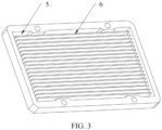
- the phase-change energy storage module includes an enclosed energy storage cavity 5 and a first thermal fin 6.
- the first thermal fin is arranged in the energy storage cavity and the phase-change material is filled in the energy storage cavity.
- the first thermal fin is integrally formed with the energy storage cavity.
- a phase-change point of the phase-change material in the phase-change energy storage module is 59°C.
- the phase-change material having the phase-change point of 59°C ensures a normal and efficient operation of the CPU.
- a CPU normal operation temperature range is 45°C-55°C.
- the water cooling module includes the heat absorption mechanism 7, a coolant pump 8, and a heat dissipation mechanism 9.
- the heat absorption mechanism is configured to absorb heat transferred from the heat conducting cavity.
- the heat absorption mechanism, the coolant pump, and the heat dissipation mechanism are connected by a hose 10.
- the coolant pump drives water in the heat absorption mechanism and water in the heat dissipation mechanism to circulate.
- the coolant pump 8 is electrically connected to a power supply 18.
- the power supply is electrically connected to a control panel 19.
- the control panel is configured to control a gear of the fan and a switch of the coolant pump.
- a temperature sensor 17 is electrically connected to the control panel.
- the control panel is electrically connected to the power supply.
- the heat absorption mechanism includes a heat transfer cavity 11 and a second thermal fin 12.
- the second thermal fin is fixed inside the heat transfer cavity, liquid water is filled in the heat transfer cavity, and the heat transfer cavity is made of red copper.
- the heat absorption mechanism is mainly configured to absorb the heat transferred from the heat conduction cavity.
- two guide isolation plates 20 are also provided in FIG. 2 .
- a main function of the guide isolation plates is liquid water backflow.
- a temperature sensor may be provided in the heat transfer cavity of the heat absorption mechanism.
- the temperature sensor can measure heat in the heat absorption mechanism to adjust a gear of a fan in the heat dissipation mechanism through the control panel.
- the temperature sensor is electrically connected to the control panel. When the temperature sensor exceeds the normal temperature, the gear of the fan is adjusted to accelerate an operation of the fan and improve heat dissipation capability.
- the heat dissipation mechanism includes a third thermal fin 13, a metal pipe 14, a fan 15, and the control panel.
- the control panel is a miniature controller. Liquid water is filled in the metal pipe. The fan releases heat from the third thermal fin and the metal pipe into the air.
- the third thermal fin is a "W-shaped" heat dissipation device. The W-shaped thermal fin dissipates heat more rapidly.
- an air pressure within the heat conduction cavity is smaller than 0.8 ⁇ 10 5 Pa. That is, the air in the heat conduction cavity is pumped to a low pressure, which is less than the standard atmospheric pressure, thereby reducing a temperature at which the liquid water vaporizes.
- the water in the heat conduction cavity continuously vaporizes and liquefies, and continuously absorbs and releases heat, thereby improving overall heat dissipation and heat conduction efficiency.
- a basic working process of the phase-change liquid cooling heat dissipation device is as follows: when a CPU temperature increases, transferring heat to the water cooling module through the liquid water and water vapor in the heat conduction cavity, and dissipating the heat through the water cooling module. Under the circumstances that the temperature exceeds heat dissipation capacity of the water cooling module, when the CPU is in the overload state and the temperature exceeds the phase-change point of the phase-change material in the phase-change energy storage module, the phase-change energy storage module starts to work and the phase-change material liquefies, thereby rapidly absorbing a large amount of heat and preventing the water cooling module from heating up. When the CPU returns to a normal load, the water cooling module also returns to a normal temperature region below the phase-change point.
- the liquefied phase-change material releases heat to re-solidify, returns the heat absorbed at the peak time to the water cooling module, and dissipates heat in the air through the heat dissipation mechanism of the water cooling module.
- the phase-change material absorbs or releases a part of the heat through phase change to prevent the CPU temperature from rising, thereby protecting a stable operation of a system.
- This embodiment utilizes a three-layer structure of the phase-change energy storage module, the water cooling module, and the heat conduction cavity.
- a function of the phase-change energy storage module reduces the CPU temperature when the CPU is in an overloaded state, thereby allowing the CPU to work normally at a normal temperature. This solves a technical problem that a computer cannot be used normally because a CPU in the computer cannot rapidly dissipate heat in an overload state which degrades performance of the CPU and shorten a service life of the CPU.
Landscapes
- Engineering & Computer Science (AREA)
- Theoretical Computer Science (AREA)
- Human Computer Interaction (AREA)
- Physics & Mathematics (AREA)
- General Engineering & Computer Science (AREA)
- General Physics & Mathematics (AREA)
- Cooling Or The Like Of Electrical Apparatus (AREA)
- Cooling Or The Like Of Semiconductors Or Solid State Devices (AREA)
Applications Claiming Priority (2)
| Application Number | Priority Date | Filing Date | Title |
|---|---|---|---|
| CN202011208539.8A CN112201637A (zh) | 2020-11-03 | 2020-11-03 | 相变液冷散热装置 |
| PCT/CN2021/093025 WO2022095397A1 (zh) | 2020-11-03 | 2021-05-11 | 相变液冷散热装置 |
Publications (2)
| Publication Number | Publication Date |
|---|---|
| EP4239671A1 true EP4239671A1 (de) | 2023-09-06 |
| EP4239671A4 EP4239671A4 (de) | 2024-05-29 |
Family
ID=74034235
Family Applications (1)
| Application Number | Title | Priority Date | Filing Date |
|---|---|---|---|
| EP21888100.1A Pending EP4239671A4 (de) | 2020-11-03 | 2021-05-11 | Wärmeableitungsvorrichtung zur kühlung einer phasenwechselflüssigkeit |
Country Status (4)
| Country | Link |
|---|---|
| US (1) | US20240258199A1 (de) |
| EP (1) | EP4239671A4 (de) |
| CN (1) | CN112201637A (de) |
| WO (1) | WO2022095397A1 (de) |
Families Citing this family (7)
| Publication number | Priority date | Publication date | Assignee | Title |
|---|---|---|---|---|
| CN112201637A (zh) * | 2020-11-03 | 2021-01-08 | 深圳市森若新材科技有限公司 | 相变液冷散热装置 |
| CN112954975A (zh) * | 2021-02-10 | 2021-06-11 | 刘沛然 | 水冷散热系统 |
| CN114025585B (zh) * | 2021-11-25 | 2025-05-27 | 爱克普传热技术(无锡)有限公司 | 一种用于电子元器件的散热装置 |
| EP4188043B1 (de) * | 2021-11-29 | 2025-04-02 | Ovh | Verfahren zur montage einer flüssigkeitskühlanordnung einer familie von flüssigkeitskühlanordnungen |
| CN115768058A (zh) * | 2022-11-21 | 2023-03-07 | 西北工业大学太仓长三角研究院 | 一种电磁学交直流分频计量装置及其使用方法 |
| GB2633595B (en) * | 2023-09-14 | 2026-03-18 | Schlumberger Cambridge Res Limited | Heat transfer system |
| CN117832686B (zh) * | 2024-02-02 | 2024-10-01 | 深圳永泰数能科技有限公司 | 基于液冷与相变材料复合散热的新型储能系统及控制方法 |
Family Cites Families (12)
| Publication number | Priority date | Publication date | Assignee | Title |
|---|---|---|---|---|
| US9019704B2 (en) * | 2009-08-27 | 2015-04-28 | Hewlett-Packard Development Company, L.P. | Heat storage by phase-change material |
| CN102270510A (zh) * | 2011-05-11 | 2011-12-07 | 杨宪宁 | 一种基于相变材料的变功耗散热器 |
| CN104080311B (zh) * | 2013-03-28 | 2019-10-18 | 北京航空航天大学 | 一种电子元器件散热器和方法 |
| EP2881690B1 (de) * | 2013-12-09 | 2016-08-17 | TuTech Innovation GmbH | Kühlvorrichtung zur Abfuhr eines Wärmestromes |
| US20180017335A1 (en) * | 2016-07-18 | 2018-01-18 | Taiwan Microloops Corp. | Water-cooling heat dissipating apparatus and vapor chamber thereof |
| CN108777927B (zh) * | 2018-06-26 | 2019-11-26 | 联想(北京)有限公司 | 一种散热装置、方法及电子设备 |
| US20200113083A1 (en) * | 2018-10-05 | 2020-04-09 | Villanova University | System and method for cooling electronic devices |
| CN210781900U (zh) * | 2019-10-25 | 2020-06-16 | 中国船舶重工集团公司第七一九研究所 | 一种连续冷却与抗热冲击冷却复合的一体式散热器 |
| CN111681999A (zh) * | 2020-05-18 | 2020-09-18 | 广东工业大学 | 一种真空导热腔均热板及风冷式散热装置 |
| CN111653536B (zh) * | 2020-05-22 | 2022-01-25 | 中国航空工业集团公司西安航空计算技术研究所 | 一种自动相变冷却系统 |
| CN212848380U (zh) * | 2020-11-03 | 2021-03-30 | 深圳市森若新材科技有限公司 | 相变液冷散热装置 |
| CN112201637A (zh) * | 2020-11-03 | 2021-01-08 | 深圳市森若新材科技有限公司 | 相变液冷散热装置 |
-
2020
- 2020-11-03 CN CN202011208539.8A patent/CN112201637A/zh active Pending
-
2021
- 2021-05-11 EP EP21888100.1A patent/EP4239671A4/de active Pending
- 2021-05-11 WO PCT/CN2021/093025 patent/WO2022095397A1/zh not_active Ceased
-
2023
- 2023-05-03 US US18/251,587 patent/US20240258199A1/en not_active Abandoned
Also Published As
| Publication number | Publication date |
|---|---|
| US20240258199A1 (en) | 2024-08-01 |
| CN112201637A (zh) | 2021-01-08 |
| WO2022095397A1 (zh) | 2022-05-12 |
| EP4239671A4 (de) | 2024-05-29 |
Similar Documents
| Publication | Publication Date | Title |
|---|---|---|
| EP4239671A1 (de) | Wärmeableitungsvorrichtung zur kühlung einer phasenwechselflüssigkeit | |
| CN1469700A (zh) | 具有储热器的散热模块 | |
| WO2022161513A2 (zh) | 计算机水冷快速散热系统 | |
| CN212848380U (zh) | 相变液冷散热装置 | |
| CN112256113A (zh) | 一种基于热电制冷的平板热管式cpu散热装置 | |
| CN111026251A (zh) | 高效组合散热式cpu散热器 | |
| CN210781900U (zh) | 一种连续冷却与抗热冲击冷却复合的一体式散热器 | |
| CN223450385U (zh) | 散热装置及服务器 | |
| CN222663205U (zh) | 一种带散热装置的充电桩 | |
| CN209525623U (zh) | 计算机快速降温水冷机箱 | |
| CN114109729B (zh) | 一种风力发电机制动装置 | |
| CN116243770A (zh) | 服务器温度的调节系统 | |
| CN201993600U (zh) | 易于散热的工控机 | |
| CN221946460U (zh) | 一种紧凑型笔记本电脑散热模组 | |
| CN221884263U (zh) | 一种集成云控制主机 | |
| CN222839988U (zh) | 一种线路板散热设备 | |
| CN224190678U (zh) | 一种低功耗型固态硬盘散热结构 | |
| CN214954896U (zh) | 贴片型半导体电子制冷片散热风扇 | |
| CN221175348U (zh) | 散热装置及服务器 | |
| CN222580489U (zh) | 一种计算机主机高效散热模组 | |
| CN223625077U (zh) | 一种单体电池 | |
| CN206058092U (zh) | 一种复合型高效cpu散热器 | |
| CN219780808U (zh) | 一种适用于双面散热功率模块的散热结构 | |
| CN206774522U (zh) | 一种芯片散热装置 | |
| CN218351645U (zh) | 一种热管理装置 |
Legal Events
| Date | Code | Title | Description |
|---|---|---|---|
| STAA | Information on the status of an ep patent application or granted ep patent |
Free format text: STATUS: THE INTERNATIONAL PUBLICATION HAS BEEN MADE |
|
| PUAI | Public reference made under article 153(3) epc to a published international application that has entered the european phase |
Free format text: ORIGINAL CODE: 0009012 |
|
| STAA | Information on the status of an ep patent application or granted ep patent |
Free format text: STATUS: REQUEST FOR EXAMINATION WAS MADE |
|
| 17P | Request for examination filed |
Effective date: 20230602 |
|
| AK | Designated contracting states |
Kind code of ref document: A1 Designated state(s): AL AT BE BG CH CY CZ DE DK EE ES FI FR GB GR HR HU IE IS IT LI LT LU LV MC MK MT NL NO PL PT RO RS SE SI SK SM TR |
|
| DAV | Request for validation of the european patent (deleted) | ||
| DAX | Request for extension of the european patent (deleted) | ||
| A4 | Supplementary search report drawn up and despatched |
Effective date: 20240429 |
|
| RIC1 | Information provided on ipc code assigned before grant |
Ipc: G06F 1/20 20060101ALI20240423BHEP Ipc: H01L 23/427 20060101ALI20240423BHEP Ipc: H01L 23/473 20060101AFI20240423BHEP |