EP4239346A1 - Zellenabtastschaltung, schaltungsfehlerfrühwarnverfahren und batterieverwaltungssystem - Google Patents
Zellenabtastschaltung, schaltungsfehlerfrühwarnverfahren und batterieverwaltungssystem Download PDFInfo
- Publication number
- EP4239346A1 EP4239346A1 EP22743435.4A EP22743435A EP4239346A1 EP 4239346 A1 EP4239346 A1 EP 4239346A1 EP 22743435 A EP22743435 A EP 22743435A EP 4239346 A1 EP4239346 A1 EP 4239346A1
- Authority
- EP
- European Patent Office
- Prior art keywords
- voltage
- impedance
- circuit
- sampling
- sampling circuit
- Prior art date
- Legal status (The legal status is an assumption and is not a legal conclusion. Google has not performed a legal analysis and makes no representation as to the accuracy of the status listed.)
- Granted
Links
Images


Classifications
-
- G—PHYSICS
- G01—MEASURING; TESTING
- G01R—MEASURING ELECTRIC VARIABLES; MEASURING MAGNETIC VARIABLES
- G01R31/00—Arrangements for testing electric properties; Arrangements for locating electric faults; Arrangements for electrical testing characterised by what is being tested not provided for elsewhere
- G01R31/36—Arrangements for testing, measuring or monitoring the electrical condition of accumulators or electric batteries, e.g. capacity or state of charge [SoC]
- G01R31/396—Acquisition or processing of data for testing or for monitoring individual cells or groups of cells within a battery
-
- G—PHYSICS
- G01—MEASURING; TESTING
- G01D—MEASURING NOT SPECIALLY ADAPTED FOR A SPECIFIC VARIABLE; ARRANGEMENTS FOR MEASURING TWO OR MORE VARIABLES NOT COVERED IN A SINGLE OTHER SUBCLASS; TARIFF METERING APPARATUS; MEASURING OR TESTING NOT OTHERWISE PROVIDED FOR
- G01D21/00—Measuring or testing not otherwise provided for
- G01D21/02—Measuring two or more variables by means not covered by a single other subclass
-
- G—PHYSICS
- G01—MEASURING; TESTING
- G01R—MEASURING ELECTRIC VARIABLES; MEASURING MAGNETIC VARIABLES
- G01R31/00—Arrangements for testing electric properties; Arrangements for locating electric faults; Arrangements for electrical testing characterised by what is being tested not provided for elsewhere
- G01R31/36—Arrangements for testing, measuring or monitoring the electrical condition of accumulators or electric batteries, e.g. capacity or state of charge [SoC]
- G01R31/3644—Constructional arrangements
- G01R31/3646—Constructional arrangements for indicating electrical conditions or variables, e.g. visual or audible indicators
-
- G—PHYSICS
- G01—MEASURING; TESTING
- G01R—MEASURING ELECTRIC VARIABLES; MEASURING MAGNETIC VARIABLES
- G01R31/00—Arrangements for testing electric properties; Arrangements for locating electric faults; Arrangements for electrical testing characterised by what is being tested not provided for elsewhere
- G01R31/36—Arrangements for testing, measuring or monitoring the electrical condition of accumulators or electric batteries, e.g. capacity or state of charge [SoC]
- G01R31/382—Arrangements for monitoring battery or accumulator variables, e.g. SoC
- G01R31/3842—Arrangements for monitoring battery or accumulator variables, e.g. SoC combining voltage and current measurements
-
- G—PHYSICS
- G01—MEASURING; TESTING
- G01R—MEASURING ELECTRIC VARIABLES; MEASURING MAGNETIC VARIABLES
- G01R31/00—Arrangements for testing electric properties; Arrangements for locating electric faults; Arrangements for electrical testing characterised by what is being tested not provided for elsewhere
- G01R31/36—Arrangements for testing, measuring or monitoring the electrical condition of accumulators or electric batteries, e.g. capacity or state of charge [SoC]
- G01R31/389—Measuring internal impedance, internal conductance or related variables
-
- G—PHYSICS
- G01—MEASURING; TESTING
- G01R—MEASURING ELECTRIC VARIABLES; MEASURING MAGNETIC VARIABLES
- G01R31/00—Arrangements for testing electric properties; Arrangements for locating electric faults; Arrangements for electrical testing characterised by what is being tested not provided for elsewhere
- G01R31/36—Arrangements for testing, measuring or monitoring the electrical condition of accumulators or electric batteries, e.g. capacity or state of charge [SoC]
- G01R31/392—Determining battery ageing or deterioration, e.g. state of health
-
- G—PHYSICS
- G08—SIGNALLING
- G08B—SIGNALLING SYSTEMS, e.g. PERSONAL CALLING SYSTEMS; ORDER TELEGRAPHS; ALARM SYSTEMS
- G08B21/00—Alarms responsive to a single specified undesired or abnormal condition and not otherwise provided for
- G08B21/18—Status alarms
-
- G—PHYSICS
- G08—SIGNALLING
- G08B—SIGNALLING SYSTEMS, e.g. PERSONAL CALLING SYSTEMS; ORDER TELEGRAPHS; ALARM SYSTEMS
- G08B21/00—Alarms responsive to a single specified undesired or abnormal condition and not otherwise provided for
- G08B21/18—Status alarms
- G08B21/185—Electrical failure alarms
-
- H—ELECTRICITY
- H01—ELECTRIC ELEMENTS
- H01M—PROCESSES OR MEANS, e.g. BATTERIES, FOR THE DIRECT CONVERSION OF CHEMICAL ENERGY INTO ELECTRICAL ENERGY
- H01M10/00—Secondary cells; Manufacture thereof
- H01M10/42—Methods or arrangements for servicing or maintenance of secondary cells or secondary half-cells
- H01M10/425—Structural combination with electronic components, e.g. electronic circuits integrated to the outside of the casing
-
- H—ELECTRICITY
- H01—ELECTRIC ELEMENTS
- H01M—PROCESSES OR MEANS, e.g. BATTERIES, FOR THE DIRECT CONVERSION OF CHEMICAL ENERGY INTO ELECTRICAL ENERGY
- H01M10/00—Secondary cells; Manufacture thereof
- H01M10/42—Methods or arrangements for servicing or maintenance of secondary cells or secondary half-cells
- H01M10/4285—Testing apparatus
-
- H—ELECTRICITY
- H01—ELECTRIC ELEMENTS
- H01M—PROCESSES OR MEANS, e.g. BATTERIES, FOR THE DIRECT CONVERSION OF CHEMICAL ENERGY INTO ELECTRICAL ENERGY
- H01M10/00—Secondary cells; Manufacture thereof
- H01M10/42—Methods or arrangements for servicing or maintenance of secondary cells or secondary half-cells
- H01M10/48—Accumulators combined with arrangements for measuring, testing or indicating the condition of cells, e.g. the level or density of the electrolyte
- H01M10/482—Accumulators combined with arrangements for measuring, testing or indicating the condition of cells, e.g. the level or density of the electrolyte for several batteries or cells simultaneously or sequentially
-
- H—ELECTRICITY
- H01—ELECTRIC ELEMENTS
- H01M—PROCESSES OR MEANS, e.g. BATTERIES, FOR THE DIRECT CONVERSION OF CHEMICAL ENERGY INTO ELECTRICAL ENERGY
- H01M10/00—Secondary cells; Manufacture thereof
- H01M10/42—Methods or arrangements for servicing or maintenance of secondary cells or secondary half-cells
- H01M10/48—Accumulators combined with arrangements for measuring, testing or indicating the condition of cells, e.g. the level or density of the electrolyte
- H01M10/488—Cells or batteries combined with indicating means for external visualization of the condition, e.g. by change of colour or of light density
-
- H—ELECTRICITY
- H02—GENERATION; CONVERSION OR DISTRIBUTION OF ELECTRIC POWER
- H02J—ELECTRIC POWER NETWORKS; CIRCUIT ARRANGEMENTS OR SYSTEMS FOR SUPPLYING OR DISTRIBUTING ELECTRIC POWER; SYSTEMS FOR STORING ELECTRIC ENERGY
- H02J7/00—Circuit arrangements for charging or discharging batteries or for supplying loads from batteries
- H02J7/80—Circuit arrangements for charging or discharging batteries or for supplying loads from batteries including monitoring or indicating arrangements
- H02J7/82—Control of state of charge [SOC]
-
- H—ELECTRICITY
- H02—GENERATION; CONVERSION OR DISTRIBUTION OF ELECTRIC POWER
- H02J—ELECTRIC POWER NETWORKS; CIRCUIT ARRANGEMENTS OR SYSTEMS FOR SUPPLYING OR DISTRIBUTING ELECTRIC POWER; SYSTEMS FOR STORING ELECTRIC ENERGY
- H02J7/00—Circuit arrangements for charging or discharging batteries or for supplying loads from batteries
- H02J7/80—Circuit arrangements for charging or discharging batteries or for supplying loads from batteries including monitoring or indicating arrangements
- H02J7/84—Control of state of health [SOH]
-
- G—PHYSICS
- G01—MEASURING; TESTING
- G01R—MEASURING ELECTRIC VARIABLES; MEASURING MAGNETIC VARIABLES
- G01R31/00—Arrangements for testing electric properties; Arrangements for locating electric faults; Arrangements for electrical testing characterised by what is being tested not provided for elsewhere
- G01R31/36—Arrangements for testing, measuring or monitoring the electrical condition of accumulators or electric batteries, e.g. capacity or state of charge [SoC]
- G01R31/367—Software therefor, e.g. for battery testing using modelling or look-up tables
-
- H—ELECTRICITY
- H01—ELECTRIC ELEMENTS
- H01M—PROCESSES OR MEANS, e.g. BATTERIES, FOR THE DIRECT CONVERSION OF CHEMICAL ENERGY INTO ELECTRICAL ENERGY
- H01M10/00—Secondary cells; Manufacture thereof
- H01M10/42—Methods or arrangements for servicing or maintenance of secondary cells or secondary half-cells
- H01M10/425—Structural combination with electronic components, e.g. electronic circuits integrated to the outside of the casing
- H01M2010/4271—Battery management systems including electronic circuits, e.g. control of current or voltage to keep battery in healthy state, cell balancing
-
- H—ELECTRICITY
- H01—ELECTRIC ELEMENTS
- H01M—PROCESSES OR MEANS, e.g. BATTERIES, FOR THE DIRECT CONVERSION OF CHEMICAL ENERGY INTO ELECTRICAL ENERGY
- H01M10/00—Secondary cells; Manufacture thereof
- H01M10/42—Methods or arrangements for servicing or maintenance of secondary cells or secondary half-cells
- H01M10/425—Structural combination with electronic components, e.g. electronic circuits integrated to the outside of the casing
- H01M2010/4278—Systems for data transfer from batteries, e.g. transfer of battery parameters to a controller, data transferred between battery controller and main controller
Definitions
- the present application relates to the field of battery management technologies, and in particular, to a cell sampling circuit, a circuit fault early warning method, and a battery management system.
- a Battery Management System In order to detect the abnormality of a battery pack in time, a Battery Management System (BMS) generally collects state data such as voltage and temperature of cells in the battery pack through a cell sampling circuit.
- state data such as voltage and temperature of cells in the battery pack through a cell sampling circuit.
- the communication of the cell sampling circuit will be interrupted, and the state data of cells will be unable to be collected due to the communication interruption.
- the state data of the cells cannot be collected, in order to ensure the safety of the cells, a high-voltage circuit of the battery pack will be quickly disconnected to ensure that the battery pack is in a safe state.
- a cell sampling circuit a circuit fault early warning method, and a battery management system are proposed in the present application, a main purpose of which is to provide early warning for an abnormality in the cell sampling circuit.
- a cell sampling circuit including: a plurality of target units sequentially connected in series by a daisy-chain communication method, a transformer unit being connected between every two adjacent target units; wherein the target unit ranked first in the series connection is a main control unit, and the rest of the target units are all cell sampling units; each of the target units is configured to acquire an impedance of the transformer unit connected thereto, and judge, based on the acquired impedance, whether to perform a circuit abnormality early warning.
- the cell sampling circuit includes a plurality of target units sequentially connected in series by a daisy-chain communication method, wherein the target unit ranked first in the series connection is the main control unit, and the rest of the target units are the cell sampling units.
- a transformer unit is connected between every two adjacent target units.
- Each of the target units is configured to acquire an impedance of the transformer unit connected thereto, and judge, based on the acquired impedance, whether to perform a circuit abnormality early warning.
- the impedance acquired by the target unit can reflect a situation that a winding of the transformer unit connected thereto is excessively pulled up, and can reflect the magnitude of a risk of disconnection of the winding of the transformer unit.
- the target unit by the method of detecting the impedance of the transformer unit connected thereto, the target unit can detect an abnormal situation of the transformer unit in time, so that when the transformer unit is abnormal and no disconnection fault has occurred yet, a circuit abnormality early warning is provided, so that the user handles the circuit abnormality in advance according to the circuit abnormality early warning.
- a target unit located upstream of the two adjacent target units is connected to a transformer input module of the transformer unit, and a target unit located downstream is connected to a transformer output module of the transformer unit; each of the target units is respectively configured to acquire an impedance of a target module connected thereto, and judge, based on the acquired impedance, whether to perform a circuit abnormality early warning, wherein the target module is determined based on a connection relationship between the target unit and the transformer unit.
- the target module when the target unit is a cell sampling unit, the target module includes a transformer output module connected thereto and a transformer input module connected thereto, and the acquired impedance includes a first impedance and a second impedance, the first impedance is the impedance of the transformer output module connected thereto, and the second impedance is the impedance of the transformer input module connected thereto.
- the target module when the target unit is a main control unit, the target module includes a transformer input module connected thereto, the acquired impedance is the second impedance, and the second impedance is the impedance of the transformer input module connected thereto.
- each of the target units is configured to perform a circuit abnormality early warning when it is determined that the acquired impedance of the target module reaches an impedance threshold corresponding to the target module.
- each of the target units is configured to determine an abnormal transformer unit, and issue a circuit abnormality early warning for the abnormal transformer unit, wherein the abnormal transformer unit is a transformer unit in which the target module whose impedance reaches the corresponding impedance threshold is located.
- the transformer output module includes: a first winding, a first switch element, a second switch element, a first connection circuit, and a second connection circuit; a first end of the first winding is connected to a first end of the first switch element through the first connection circuit, and a second end is connected to a first end of the second switch element through the second connection circuit; and a second end of the first switch element and a second end of the second switch element are respectively connected to the cell sampling unit.
- the cell sampling unit includes: a first voltage sampling circuit, a second voltage sampling circuit, a first voltage adjustment circuit, and a control chip; a first end of the first voltage adjustment circuit is connected to a first node, a second end is connected to a ground wire; a first end of the first voltage sampling circuit is connected to the first node, and a second end is connected to a first pin of the control chip; a first end of the second voltage sampling circuit is connected to a second node, and a second end is connected to a second pin of the control chip; the first node is connected to the second end of the first switch element, and is connected to a third pin of the control chip; the second node is connected to the second end of the second switch element, and is connected to a fourth pin of the control chip.
- control chip is configured to collect a first sampling voltage corresponding to the first voltage sampling circuit and a second sampling voltage corresponding to the second voltage sampling circuit, and determine the first impedance based on the first sampling voltage, the second sampling voltage, and a first resistance of the first voltage adjustment circuit.
- the cell sampling unit further includes: a second voltage adjustment circuit and a third voltage sampling circuit; a first end of the second voltage adjustment circuit is connected to the second node, and a second end is connected to a first end of the third voltage sampling circuit; and a second end of the third voltage sampling circuit is connected to a fifth pin of the control chip.
- control chip is configured to collect a second sampling voltage corresponding to the second voltage sampling circuit and a third sampling voltage corresponding to the third voltage sampling circuit, and determine the first impedance based on the second sampling voltage, the third sampling voltage, a first resistance of the first voltage adjustment circuit, and a second resistance of the second voltage adjustment circuit.
- control chip is configured to collect a first sampling voltage corresponding to the first voltage sampling circuit and a third sampling voltage corresponding to the third voltage sampling circuit, and determine the first impedance based on the first sampling voltage, the third sampling voltage, a first resistance of the first voltage adjustment circuit, and a second resistance of the second voltage adjustment circuit.
- the first impedance is a sum of an impedance of the first winding, an impedance of the first switch element, an impedance of the second switch element, an impedance of the first connection circuit, and an impedance of the second connection circuit in the transformer output module under daisy-chain communication.
- the transformer input module includes: a second winding, a third switch element, and a fourth switch element; a first end of the second winding is connected to a first end of the third switch element, and a second end is connected to a first end of the fourth switch element; and a second end of the third switch element and a second end of the fourth switch element are respectively connected to the target unit.
- the target unit includes: a fourth voltage sampling circuit, a fifth voltage sampling circuit, a third voltage adjustment circuit, and a control chip; a first end of the third voltage adjustment circuit is connected to a third node, a second end is connected to a ground wire; a first end of the fourth voltage sampling circuit is connected to the third node, and a second end is connected to a sixth pin of the control chip; a first end of the fifth voltage sampling circuit is connected to a fourth node, and a second end is connected to a seventh pin of the control chip; the third node is connected to a second end of the third switch element, and is connected to an eighth pin of the control chip; the fourth node is connected to a second end of the fourth switch element, and is connected to a ninth pin of the control chip.
- control chip is configured to collect a fourth sampling voltage corresponding to the fourth voltage sampling circuit and a fifth sampling voltage corresponding to the fifth voltage sampling circuit, and determine the second impedance based on the fourth sampling voltage, the fifth sampling voltage, and a third resistance of the third voltage adjustment circuit.
- the target unit further includes: a fourth voltage adjustment circuit and a sixth voltage sampling circuit; a first end of the fourth voltage adjustment circuit is connected to the fourth node, and a second end is connected to a first end of the sixth voltage sampling circuit; and a second end of the sixth voltage sampling circuit is connected to a tenth pin of the control chip.
- control chip is configured to collect a sixth sampling voltage corresponding to the sixth voltage sampling circuit and a fifth sampling voltage corresponding to the fifth voltage sampling circuit, and determine the second impedance based on the sixth sampling voltage, the fifth sampling voltage, a third resistance of the third voltage adjustment circuit, and a fourth resistance corresponding to the fourth voltage adjustment circuit.
- control chip is configured to collect a sixth sampling voltage corresponding to the sixth voltage sampling circuit and a fourth sampling voltage corresponding to the fourth voltage sampling circuit, and determine the second impedance based on the fourth sampling voltage, the sixth sampling voltage, a third resistance of the third voltage adjustment circuit, and a fourth resistance corresponding to the fourth voltage adjustment circuit.
- the second impedance is a sum of an impedance of the second winding, an impedance of the third switch element, and an impedance of the fourth switch element in the transformer input module under daisy-chain communication.
- a circuit fault early warning method applied to a cell sampling circuit including: a plurality of target units sequentially connected in series by a daisy-chain communication method, a transformer unit being connected between every two adjacent target units; wherein the target unit ranked first in the series connection is a main control unit, the rest of the target units are all cell sampling units, and the method includes performing actions, for each of the target units, including acquiring an impedance of the transformer unit connected thereto, and judging, based on the acquired impedance, whether to perform a circuit abnormality early warning.
- a battery management system in the present application, and the battery management system includes the cell sampling circuit according to any one of the first aspect.
- a battery in the present application, and the battery includes the battery management system according to the third aspect.
- a powered device in the present application, and the powered device includes the battery according to the fourth aspect.
- a computer-readable storage medium in the present application, the storage medium includes a stored program, wherein the program, during running, controls a device where the storage medium is located to perform the circuit fault early warning method according to any one of the second aspect.
- the term "and/or" is only an association relationship for describing associated objects, indicating that there may be three types of relationships.
- a and/or B may indicate three cases including: A exists, both A and B exist, and B exists.
- the character "/" herein generally indicates that the associated objects before and after the character are in an "or" relationship.
- a plurality of refers to two or more (including two), similarly, “a plurality of groups” refers to two or more groups (including two groups), and “a plurality of pieces” refers to of two or more pieces (including two pieces).
- orientations or positional relationships indicated by technical terms such as “center,” “longitudinal,” “lateral,” “length,” “width,” “thickness,” “upper,” “lower,” “front,” “rear,” “left,” “right,” “vertical” “horizontal,” “top,” “bottom,” “inside,” “outside,” “clockwise,” “counterclockwise,” “axial,” “radial,” and “circumferential” are based on orientations or positional relationships shown in the accompanying drawings, are only for the convenience of describing the embodiments of the present application and simplifying the description, rather than indicating or implying that the indicated apparatus or element must have a specific orientation or be constructed and operated in a specific orientation, and therefore cannot be understood as limitation to the embodiments of the present application.
- a battery pack is usually composed of a plurality of cells connection in series and parallel, and states of the cells directly affect the safety of the battery.
- states of the cells directly affect the safety of the battery.
- state data such as voltage and temperature of various cells in the battery pack in real time during the use of the battery pack, so as to accurately control and protect charging and discharging processes of the battery pack based on the state data.
- a battery management system collects state data of cells by a cell sampling circuit.
- the current cell sampling circuit mostly adopts a distributed solution.
- a plurality of cell sampling units in the cell sampling circuit are responsible for the collection of the state data of the cells, and the main control unit in the cell sampling circuit is responsible for performing processing and control according to state parameters collected by the cell sampling units.
- the transformer unit is mainly configured to achieve electrical isolation between components in the cell sampling circuit. Limited by the manufacturing process of the transformer unit, faults such as transformer disconnection often occur during the actual use of the cell sampling circuit.
- the fault of the transformer will cause the communication of the cell sampling circuit to be interrupted, and the state data such as the voltage and temperature of the cells cannot be collected.
- the occurrence of the transformer fault is only detected after the battery pack enters a safe state, and the battery pack entering the safe state will directly prevent the user from using the battery pack, causing inconvenience to the user when using the battery pack.
- a cell sampling circuit can be designed so that before an abnormality occurs in the transformer unit, and the abnormality does not cause the communication of the cell sampling circuit to be interrupted, the circuit abnormality is warned in advance to give the user a circuit abnormality early warning, so that the user can handle the abnormality based on the early warning in advance.
- the cell sampling circuit includes: a plurality of target units sequentially connected in series by a daisy-chain communication method, a transformer unit being connected between every two adjacent target units; wherein the target unit ranked first in the series connection is a main control unit, and the rest of the target units are all cell sampling units; each of the target units is configured to acquire an impedance of the transformer unit connected thereto, and judge, based on the acquired impedance, whether to perform a circuit abnormality early warning.
- a battery management system provided with a cell sampling circuit is disclosed in an embodiment of the present application, so that the battery management system performs battery control and association based on data collected by the cell sampling circuit.
- the battery provided with the battery management system disclosed in the embodiments of the present application can be used in, but not limited to, powered devices such as vehicles, ships, or aircraft.
- a power supply system for the powered device may be formed by using the battery and the like disclosed in the present application.
- a powered device using a battery as a power supply is provided in the embodiment of the present application, and the powered device may be, but is not limited to, a mobile phone, a tablet, a laptop, an electric toy, an electric tool, an electric bicycle, an electric vehicle, a ship, a spacecraft, and the like.
- the electric toy may include a stationary or mobile electric toy, such as a game console, an electric car toy, an electric ship toy, and an electric airplane toy
- the spacecraft may include an airplane, a rocket, a space shuttle, a spaceship, and the like.
- a cell sampling circuit is provided in an embodiment of the present application.
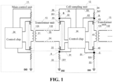
- the cell sampling circuit includes: a plurality of target units sequentially connected in series by a daisy-chain communication method, wherein the target unit ranked first in the series connection is main control unit 11, and the rest of the target units are all cell sampling units 12; and transformer unit 13 is connected between every two adjacent target units.
- Each of the target units is respectively configured to acquire an impedance of transformer unit 13 connected thereto, and judge, based on the acquired impedance, whether to perform a circuit abnormality early warning.
- Main control unit 11 and at least one cell sampling unit 12 are both target units, which are sequentially connected in series by the daisy-chain communication method.
- Main control unit 11 ranked first in the series connection As shown in Fig. 1 , only two target units among the plurality of target units connected in series are shown in Fig. 1 , and the rest of the target units are not shown.
- the target unit ranked first is main control unit 11.
- the other target units are all cell sampling units 12 and are connected in series behind main control unit 11.
- the daisy-chain communication method is adopted between the target units, and therefore, transformer unit 13 is connected between every two adjacent target units, so as to realize electrical isolation between the target units by using transformer unit 13.
- the main reason for the fault of the cell sampling circuit is a fault of transformer unit 13 in the cell sampling circuit. Therefore, it is necessary to monitor transformer unit 13, so as to detect the abnormality in time and give an early warning of the abnormality of the circuit when there is an abnormality but no fault occurs.
- the fault of transformer unit 13 is mainly a disconnection fault.
- the disconnection fault is usually caused by excessive pulling up of a winding of the transformer when the transformer structure expands or contracts due temperature changes.
- the winding is pulled up excessively when the transformer structure expands or contracts, which will inevitably cause an impedance of transformer unit 13 to increase. Therefore, by acquiring the impedance of transformer unit 13, it can be determined whether to perform a circuit abnormality early warning.
- the job of acquiring the impedance of transformer unit 13 is done by the target unit.
- Each of the target units is respectively configured to acquire the impedance of transformer unit 13 connected thereto.
- the impedance acquired by the target unit can reflect a situation that the winding of transformer unit 13 connected thereto is excessively pulled up, which can reflect the risk of disconnection of the winding of transformer unit 13. Therefore, the target unit can judge, based on the acquired impedance of transformer unit 13 connected thereto, whether to perform a circuit abnormality early warning. Once the target unit determines, based on the acquired impedance, that there is a risk of disconnection in the cell sampling circuit, a circuit abnormality early warning is issued, so that the user can handle the warning in time.
- the cell sampling circuit includes a plurality of target units sequentially connected in series by a daisy-chain communication method, wherein the target unit ranked first in the series connection is the main control unit, and the rest of the target units are the cells sampling units.
- a transformer unit is connected between every two adjacent target units.
- Each of the target units is configured to acquire an impedance of the transformer unit connected thereto, and judge, based on the acquired impedance, whether to perform a circuit abnormality early warning.
- the impedance acquired by the target unit can reflect a situation that a winding of the transformer unit connected thereto is excessively pulled up, and can reflect the magnitude of a risk of disconnection of the winding of the transformer unit.
- the target unit by the method of detecting the impedance of the transformer unit connected thereto, the target unit can detect an abnormal situation of the transformer unit in time, so that when the transformer unit is abnormal and no disconnection fault has occurred yet, a circuit abnormality early warning is provided, so that the user handles the circuit abnormality in advance according to the circuit abnormality early warning.
- the target unit located upstream of the two adjacent target units is connected to transformer input module 131 of transformer unit 13, and the target unit located downstream is connected to transformer output module 132 of transformer unit 13.
- Each of the target units is configured to acquire an impedance of the target module connected thereto, and judge, based on the acquired impedance, whether to perform a circuit abnormality early warning, wherein the target module is determined based on a connection relationship between the target unit and transformer unit 13.
- Transformer unit 13 includes transformer input module 131 and transformer output module 132.
- the target unit located upstream of the two adjacent target units is connected to transformer input module 131 of transformer unit 13, and the target unit located downstream is connected to transformer output module 132 of transformer unit 13.
- the upstream and the downstream are determined based on a communication direction between main control chip 11 and each cell sampling unit 12, and the communication direction from main control chip 11 to the last cell sampling unit 12 is defined as from upstream to downstream.
- main control unit 11 is the target unit located upstream
- cell sampling unit 12 is the target unit located downstream.
- cell sampling unit 12 close to main control unit 11 is the target unit located upstream
- the other cell sampling unit 12 is the target unit located upstream.
- each target unit In order to detect the abnormality of transformer unit 13 in time, each target unit needs to acquire the impedance of transformer unit 13 connected thereto. When each target unit acquires the impedance, it only acquires the impedance of the target module connected thereto. For a target unit, its corresponding target module is determined based on its connection relationship with transformer unit 13.
- the target module connected thereto includes transformer input module 131 connected thereto.
- the target unit is main control unit 11
- the target module is transformer input module 131 in transformer unit 13 connected thereto.
- Main control unit 11 can monitor the abnormality of transformer unit 13 by acquiring the impedance of transformer input module 131 connected thereto.
- the target module connected thereto includes transformer output module 132 connected thereto and transformer input module 131 connected thereto.
- the target unit is cell sampling unit 12 adjacent to main control unit 11. Both sides of cell sampling unit 12 is connected to transformer unit 13, so there are two target modules connected to: one is transformer output module 132 in transformer unit 13 connected upstream thereto, and the other is transformer input module 131 in transformer unit 13 connected downstream thereto.
- the target module connected thereto includes transformer output module 132 connected thereto and transformer input module 131 connected thereto
- the acquired impedance includes a first impedance and a second impedance.
- the first impedance is the impedance of transformer output module 132 connected thereto
- the second impedance is the impedance of transformer input module 131 connected thereto.
- both sides of cell sampling unit 12 are connected to transformer units 13, and therefore, it can monitor conditions of two transformer units 13 at the same time. Therefore, cell sampling unit 12 needs to acquire the first impedance of transformer output module 132 connected thereto and the second impedance of transformer input module 131 connected thereto.
- the first impedance can reflect a situation that the winding of transformer output module 132 in transformer unit 13 is excessively pulled up, and can reflect the risk of disconnection of the winding of transformer output module 132.
- the second impedance can reflect a situation that the winding of transformer input module 131 in transformer unit 13 is excessively pulled up, and can reflect the risk of disconnection of the winding of transformer input module 131.
- cell sampling unit 12 can determine the disconnection risk of the winding of transformer output module 132 connected thereto according to the magnitude of the first impedance collected, and issue a circuit abnormality early warning when the risk is determined to be high, so as to provide a circuit abnormality early warning when an abnormality occurs in the transformer unit and a disconnection fault has not yet occurred, so that the user can handle the circuit abnormality in advance according to the circuit abnormality early warning.
- cell sampling unit 12 can determine the disconnection risk of the winding of transformer input module 131 connected thereto according to the magnitude of the second impedance collected, and issue a circuit abnormality early warning when the risk is determined to be high, so as to provide a circuit abnormality early warning when an abnormality occurs in the transformer unit and a disconnection fault has not yet occurred, so that the user can handle the circuit abnormality in advance according to the circuit abnormality early warning.
- the target module connected thereto includes transformer input module 131 connected thereto, the acquired impedance is a second impedance, and the second impedance is the impedance of transformer input module 131 connected thereto.
- main control unit 11 As shown in Fig. 1 , one side of main control unit 11 is connected to transformer unit 13, which can monitor the condition of transformer unit 13 connected thereto. Therefore, main control unit 11 needs to acquire the second impedance of transformer input module 131 connected thereto.
- the second impedance can reflect a situation that the winding of transformer input module 131 in transformer unit 13 is excessively pulled up, and can reflect the risk of disconnection of the winding of transformer input module 131.
- Main control unit 11 can determine the disconnection risk of the winding of transformer input module 131 connected thereto according to the magnitude of the second impedance collected, and issue a circuit abnormality early warning when the risk is determined to be high, so as to provide a circuit abnormality early warning when an abnormality occurs in the transformer unit and a disconnection fault has not yet occurred, so that the user can handle the circuit abnormality in advance according to the circuit abnormality early warning.
- each of the target units is configured to perform a circuit abnormality early warning when it is determined that the acquired impedance of the target module reaches an impedance threshold corresponding to the target module.
- the connected target modules For a target unit, the connected target modules have their respective corresponding impedance thresholds.
- the impedance threshold is an upper limit of the impedance of the winding of the target module. Once the impedance of the target module reaches the impedance threshold, the possibility of disconnection thereof increases. Therefore, after acquiring the impedance of the target module, the target unit needs to compare the acquired impedance of the target module with the impedance threshold corresponding to the target module.
- the target unit determines that the acquired impedance of the target module reaches the impedance threshold corresponding to the target module, it indicates that the stretching of the winding of the target module has caused a high risk of disconnection. Therefore, it is necessary to carry out a circuit abnormality early warning for the target module, so that the user handles the early warning of the risk of disconnection of the cell sampling circuit.
- the target unit determines that the acquired impedance of the target module does not reach the impedance threshold corresponding to the target module, it indicates that the stretching of the winding of the target module has not caused a greater risk of disconnection, and there is no need to perform a circuit abnormality early warning for the target module.
- the target unit when the target unit is main control unit 11, if it is determined that a circuit abnormality early warning needs to be performed, it can directly perform the early warning processing. If the target unit is cell sampling unit 12, in order to reduce the processing volume of cell sampling unit 12, when cell sampling unit 12 determines that a circuit abnormality early warning needs to be performed, it may transmit the requirement for the circuit abnormality early warning to main control unit 11 by the daisy-chain communication, and main control unit 11 performs the circuit abnormality early warning processing thereof.
- each of the target units is configured to determine an abnormal transformer unit, and issue a circuit abnormality early warning for the abnormal transformer unit, wherein the abnormal transformer unit is transformer unit 13 in which the target module whose impedance reaches the corresponding impedance threshold is located.
- the target unit determines the abnormal transformer unit when it is determined that the acquired impedance of the target module reaches the impedance threshold value corresponding to the target module, and issues a circuit abnormality early warning for the abnormal transformer unit.
- the abnormal transformer unit is transformer unit 13 in which the target module whose impedance reaches the corresponding impedance threshold is located.
- the abnormal transformer unit expands or contracts due to the temperature change of the transformer structure, the winding of the target module is excessively pulled up, and there is a risk of disconnection.
- a circuit abnormality early warning is issued for the abnormal transformer unit, so that the maintenance personnel can accurately know which transformer unit 13 has the risk of disconnection, so that it can be quickly and targeted for repairing and replacement, thereby improving the repairing efficiency.
- transformer output module 132 includes: first winding 21, first switch element 22, second switch element 23, first connection circuit 24, and second connection circuit 25.
- a first end of first winding 21 is connected to a first end of first switch element 22 through first connection circuit 24, and a second end is connected to a first end of second switch element 23 through second connection circuit 25; and a second end of first switch element 22 and a second end of second switch element 23 are respectively connected to cell sampling unit 11.
- First winding 21, first switch element 22, second switch element 23, first connection circuit 24, and second connection circuit 25 constitute transformer output module 132.
- First winding 21, first connection circuit 24, and second connection circuit 25 will all be excessively stretched during the use of the cell sampling circuit, and there is a risk of disconnection.
- the excessively stretching described here is caused by the expansion or contraction of the transformer structure due to the temperature change during the use of the cell sampling circuit.
- first winding 21, first connection circuit 24, and second connection circuit 25 may all be excessively stretched, and there is a risk of disconnection. After first winding 21, first connection circuit 24, and second connection circuit 25 are stretched, their respective impedances will increase. Therefore, first impedance Rn can reflect whether there is a risk of disconnection in first winding 21, first connection circuit 24, and second connection circuit 25, and can be used as a judgment basis for the circuit abnormality early warning.
- cell sampling unit 12 includes: first voltage sampling circuit 31, second voltage sampling circuit 32, first voltage adjustment circuit 33, and control chip 34.
- a first end of first voltage adjustment circuit 33 is connected to first node A, and a second end is connected to ground wire GND.
- a first end of first voltage sampling circuit 31 is connected to first node A, and a second end is connected to a first pin of control chip 34.
- a first end of second voltage sampling circuit 32 is connected to second node B, and a second end is connected to a second pin of control chip 34.
- First node A is connected to the second end of first switch element 22, and is connected to a third pin of control chip 34.
- Second node B is connected to the second end of second switch element 23, and is connected to a fourth pin of control chip 34.
- Control chip 34 is configured to acquire the first impedance Rn of transformer output module 132 connected thereto.
- First voltage sampling circuit 31, second voltage sampling circuit 32, and first voltage adjustment circuit 33 are all configured to assist control chip 34 to acquire first impedance Rn.
- the magnitude of the impedance of transformer output module 132 will cause a voltage change in second voltage sampling circuit 32.
- First voltage adjustment circuit 33 includes voltage adjusting resistor 331 configured to adjust the voltage.
- control chip 34 is configured to collect first sampling voltage U1 corresponding to first voltage sampling circuit 31 and second sampling voltage U2 corresponding to second voltage sampling circuit 32, and determine first impedance Rn based on first sampling voltage U1, second sampling voltage U2, and first resistance R1 of first voltage adjustment circuit 33.
- first sampling voltage U1 and second sampling voltage U2 in the above formula can be collected, and first resistance R1 is known in advance, first impedance Rn can be determined by the above formula.
- cell sampling unit 12 further includes: second voltage adjustment circuit 35 and third voltage sampling circuit 36.
- First end of second voltage adjustment circuit 35 is connected to second node B, and a second end is connected to a first end of third voltage sampling circuit 36; and a second end of third voltage sampling circuit 36 is connected to a fifth pin of control chip 34.
- Second voltage adjustment circuit 35 and third voltage sampling circuit 36 are both configured to assist control chip 34 to acquire first impedance Rn.
- Second voltage adjustment circuit 35 includes voltage adjusting resistor 351 configured to adjust the voltage. The magnitude of the impedance of transformer output module 132 will cause a voltage change in third voltage sampling circuit 36.
- control chip 34 is configured to collect second sampling voltage U2 corresponding to second voltage sampling circuit 32 and third sampling voltage U3 corresponding to third voltage sampling circuit 36, and determine first impedance Rn based on second sampling voltage U2, third sampling voltage U3, first resistance R1 of first voltage adjustment circuit 33, and second resistance R2 of second voltage adjustment circuit 35.
- first impedance Rn can be determined by the above formula.
- control chip 34 is configured to collect first sampling voltage U1 corresponding to first voltage sampling circuit 31 and third sampling voltage U3 corresponding to third voltage sampling circuit 36, and determine first impedance Rn based on first sampling voltage U1, third sampling voltage U3, first resistance R1 of first voltage adjustment circuit 33, and second resistance R2 of second voltage adjustment circuit 35.
- first impedance Rn can be determined by the above formula.
- the first impedance is a sum of the impedance of first winding 21, the impedance of first switch element 22, the impedance of second switch element 23, the impedance of first connection circuit 24, and the impedance of second connection circuit 25 in transformer output module 132 under daisy-chain communication.
- First impedance Rn corresponding to transformer output module 132 is a sum of the impedance of first winding 21, the impedance of first switch element 22, the impedance of second switch element 23, the impedance of first connection circuit 24, and the impedance of second connection circuit 25 in transformer output module 132. After first winding 21, first connection circuit 24, and second connection circuit 25 are stretched, their respective impedances will increase. Therefore, first impedance Rn can reflect whether there is a risk of disconnection in first winding 21, first connection circuit 24, and second connection circuit 25, and can be used as a judgment basis for the circuit abnormality early warning.
- transformer input module 131 includes: second winding 41, third switch element 42, and fourth switch element 43.
- a first end of second winding 41 is connected to a first end of third switch element 42, and a second end is connected to fourth switch element 43.
- a second end of third switch element 42 and a second end of fourth switch element 43 are respectively connected to the target unit.
- both main control unit 31 and cell sampling unit 32 need their corresponding transformer input modules 131, and therefore, the target unit connected to the second end of third switch element 42 and the second end of fourth switch element 43, in a specific connection scenario, is main control unit 31 or cell sampling unit 32. Specific description is shown in Fig. 1 .
- Second winding 41, third switch element 42, and fourth switch element 43 constitute transformer input module 131.
- Second winding 41 will be excessively stretched during the use of the cell sampling circuit, and there is a risk of disconnection.
- the excessively stretching described here is caused by the expansion or contraction of the transformer structure due to the temperature change during the use of the cell sampling circuit.
- the target unit includes: fourth voltage sampling circuit 51, fifth voltage sampling circuit 52, third voltage adjustment circuit 53, and control chip 34.
- a first end of third voltage adjustment circuit 53 is connected to third node C, and a second end is connected to ground wire GND.
- a first end of fourth voltage sampling circuit 51 is connected to third node C, and a second end is connected to a sixth pin of control chip 54.
- a first end of fifth voltage sampling circuit 52 is connected to fourth node D, and a second end is connected to a seventh pin of control chip 34.
- Third node C is connected to the second end of third switch element 42, and is connected to an eighth pin of control chip 34.
- Fourth node D is connected to the second end of fourth switch element 43, and is connected to a ninth pin of control chip 34.
- the target unit described here includes main control unit 11 and cell sampling unit 12.
- Control chip 34 included in the target unit has the same function in main control unit 11 and cell sampling unit 12, that is, acquiring second impedance Rm of first transformer input module 131, and judging, based on second impedance Rm, whether to perform a circuit abnormality early warning. However, they also have different functions.
- the main control chip in the main control unit is configured to perform battery management based on voltage state data collected by cell sampling unit 12, and cell sampling unit 12 is configured to collect the state data of the cell.
- Control chip 34 is configured to acquire second impedance Rm of transformer input module 131 connected thereto.
- Fourth voltage sampling circuit 51, fifth voltage sampling circuit 52, and third voltage adjustment circuit 53 are all configured to assist control chip 34 to acquire second impedance Rm.
- the magnitude of the impedance of transformer input module 131 will cause voltage changes in fourth voltage sampling circuit 51 and fifth voltage sampling circuit 52.
- Third voltage adjustment circuit 53 includes voltage adjusting resistor 531 configured to adjust the voltage.
- control chip 54 is configured to collect fourth sampling voltage U4 corresponding to fourth voltage sampling circuit 51 and fifth sampling voltage U5 corresponding to fifth voltage sampling circuit 52, and determine second impedance Rm based on fourth sampling voltage U4, fifth sampling voltage U5, and third resistance R3 of third voltage adjustment circuit 53.
- second impedance Rm can be determined by the above formula.
- the target unit further includes: fourth voltage adjustment circuit 54 and sixth voltage sampling circuit 55.
- a first end of fourth voltage adjustment circuit 54 is connected to fourth node D, and a second end is connected to a first end of sixth voltage sampling circuit 55; and a second end of sixth voltage sampling circuit 55 is connected to a tenth pin of control chip 54.
- Both fourth voltage adjustment circuit 54 and sixth voltage sampling circuit 55 are both configured to assist control chip 34 to acquire second impedance Rm.
- Fourth voltage adjustment circuit 54 includes voltage adjusting resistor 541 configured to adjust the voltage. The magnitude of the impedance of transformer input module 131 will cause a voltage change in sixth voltage sampling circuit 55.
- control chip 54 is configured to collect sixth sampling voltage U6 corresponding to sixth voltage sampling circuit 55 and fifth sampling voltage U5 corresponding to fifth voltage sampling circuit 52, and determine second impedance Rm based on sixth sampling voltage U6, fifth sampling voltage U5, third resistance R3 of third voltage adjustment circuit 53, and fourth resistance R4 of fourth voltage adjustment circuit 54.
- second impedance Rm can be determined by the above formula.
- control chip 54 is configured to collect sixth sampling voltage U6 corresponding to sixth voltage sampling circuit 55 and fourth sampling voltage U4 corresponding to fourth voltage sampling circuit 51, and determine second impedance Rm based on fourth sampling voltage U4, sixth sampling voltage U6, third resistance R3 of third voltage adjustment circuit 53, and fourth resistance R4 of fourth voltage adjustment circuit 54.
- second impedance Rm can be determined by the above formula.
- second impedance Rm is a sum of the impedance of second winding 41, the impedance of third switch element 42, and the impedance of fourth switch element 43 in transformer input module 131 under daisy-chain communication.
- Second impedance Rm corresponding to transformer input module 131 is a sum of the impedance of second winding 41, the impedance of third switch element 42, and the impedance of fourth switch element 43 in transformer input module 131. After second winding 41 is stretched, its corresponding impedance will increase. Therefore, second impedance Rm can reflect whether there is a risk of disconnection of second winding 41, and can be used as a judgment basis for circuit abnormality early warning.
- each cell sampling unit 12 in the cell sampling circuit has at least one corresponding cell D, and is connected to corresponding cell D through a line, and configured to collect state data such as voltage and temperature of corresponding battery cell D, and transmit the state data to main control unit 11.
- Main control unit 11 is configured to perform battery management based on the voltage state data collected by cell sampling unit 12.
- the cell sampling circuit shown in Fig. 2 can not only monitor the state of the cells in the battery pack in real time, but also the main control unit and the cell sampling unit can discover an abnormal situation of the transformer unit by detecting the impedance of the transformer unit connected thereto in time. Therefore, when the transformer unit is abnormal and the disconnection fault has not yet occurred, a circuit abnormality early warning is given, so that the user can handle the circuit abnormality in advance according to the circuit abnormality early warning.
- a circuit fault early warning method is further provided in another embodiment of the present application, which is applied to a cell sampling circuit as shown in Fig. 3 .
- the cell sampling circuit includes a plurality of target units sequentially connected in series by a daisy-chain communication method, a transformer unit is connected between every two adjacent target units, the target unit ranked first in the series connection is a main control unit, and the rest of the target units are all cell sampling units; and the method mainly includes:
- the circuit fault early warning method provided by the embodiment of the present application is applied to the cell sampling circuit, and an abnormal situation of the transformer unit can be discovered in time by detecting the impedance of the transformer unit connected to the target units. Therefore, when the transformer unit is abnormal and the disconnection fault has not yet occurred, a circuit abnormality early warning is given, so that the user can handle the circuit abnormality in advance according to the circuit abnormality early warning.
- a battery management system is further provided in another embodiment of the present application, and the battery management system includes the cell sampling circuit as described above.
- the cell sampling circuit included in the battery management system provided by the embodiment of the present application can discover the abnormal situation of the transformer unit in time by detecting the impedance of the transformer unit connected to each target unit, so that the abnormality occurs in the transformer unit and has not yet occurred.
- a circuit abnormality early warning is given, so that the user can handle the circuit abnormality in advance according to the circuit abnormality early warning.
- a battery is further provided in another embodiment of the present application, and the battery includes the battery management system as described above.
- a powered device is further provided in another embodiment of the present application, and the powered device includes the battery as described above.
- a computer-readable storage medium is further provided in another embodiment of the present application, wherein the storage medium includes a stored program, and the program, during running, controls a device where the storage medium is located to perform the circuit fault early warning method described above.
Landscapes
- Engineering & Computer Science (AREA)
- General Physics & Mathematics (AREA)
- Physics & Mathematics (AREA)
- Chemical Kinetics & Catalysis (AREA)
- Chemical & Material Sciences (AREA)
- Electrochemistry (AREA)
- General Chemical & Material Sciences (AREA)
- Manufacturing & Machinery (AREA)
- Power Engineering (AREA)
- Business, Economics & Management (AREA)
- Microelectronics & Electronic Packaging (AREA)
- Emergency Management (AREA)
- Charge And Discharge Circuits For Batteries Or The Like (AREA)
- Health & Medical Sciences (AREA)
- General Health & Medical Sciences (AREA)
- Medical Informatics (AREA)
- Secondary Cells (AREA)
- Testing Electric Properties And Detecting Electric Faults (AREA)
Applications Claiming Priority (2)
| Application Number | Priority Date | Filing Date | Title |
|---|---|---|---|
| CN202210018432.XA CN115825794B (zh) | 2022-01-07 | 2022-01-07 | 电芯采样电路、电路故障预警方法及电池管理系统 |
| PCT/CN2022/089552 WO2023130625A1 (zh) | 2022-01-07 | 2022-04-27 | 电芯采样电路、电路故障预警方法及电池管理系统 |
Publications (4)
| Publication Number | Publication Date |
|---|---|
| EP4239346A1 true EP4239346A1 (de) | 2023-09-06 |
| EP4239346A4 EP4239346A4 (de) | 2023-12-27 |
| EP4239346C0 EP4239346C0 (de) | 2025-01-01 |
| EP4239346B1 EP4239346B1 (de) | 2025-01-01 |
Family
ID=87069429
Family Applications (1)
| Application Number | Title | Priority Date | Filing Date |
|---|---|---|---|
| EP22743435.4A Active EP4239346B1 (de) | 2022-01-07 | 2022-04-27 | Zellenabtastschaltung, schaltungsfehlerfrühwarnverfahren und batterieverwaltungssystem |
Country Status (4)
| Country | Link |
|---|---|
| US (1) | US12352822B2 (de) |
| EP (1) | EP4239346B1 (de) |
| JP (1) | JP7528231B2 (de) |
| KR (1) | KR102758912B1 (de) |
Family Cites Families (34)
| Publication number | Priority date | Publication date | Assignee | Title |
|---|---|---|---|---|
| US5254930A (en) | 1992-06-10 | 1993-10-19 | Digital Equipment Corporation | Fault detector for a plurality of batteries in battery backup systems |
| JPH06222101A (ja) * | 1993-01-26 | 1994-08-12 | Denshi Seiki Kogyo Kk | コイル試験方法とその方法に用いる装置 |
| CA2338282A1 (en) | 1998-07-21 | 2000-02-03 | Metrixx Limited | Signalling system |
| EP1384305A4 (de) * | 2001-05-02 | 2005-11-09 | Microchip Tech Inc | Verfahren und vorrichtung für ein überwachungssensornetzwerk für ein hochspannungs-batteriearray |
| CN101261297B (zh) * | 2008-04-17 | 2010-11-17 | 沈阳工业大学 | 电力变压器绕组参数在线实时辨识装置及方法 |
| CN101409455B (zh) | 2008-11-19 | 2011-10-26 | 华为终端有限公司 | 一种电池系统的电压平衡装置及电压平衡方法 |
| US8570047B1 (en) | 2009-02-12 | 2013-10-29 | The United States Of America As Represented By The Administrator Of The National Aeronautics And Space Administration | Battery fault detection with saturating transformers |
| JP5392166B2 (ja) * | 2010-04-02 | 2014-01-22 | トヨタ自動車株式会社 | 燃料電池システム |
| JP5456582B2 (ja) * | 2010-06-01 | 2014-04-02 | 一般財団法人電力中央研究所 | 変圧器の健全性診断方法、健全性診断装置及び健全性診断プログラム |
| CN104603627B (zh) | 2012-09-10 | 2017-11-03 | 瑞萨电子株式会社 | 半导体装置和电池电压监视装置 |
| JP5978143B2 (ja) | 2013-01-25 | 2016-08-24 | 株式会社ケーヒン | 蓄電池システム |
| CN104316826B (zh) | 2014-11-17 | 2018-07-20 | 国家电网公司 | 一种检测变压器绕组故障类型的方法及系统 |
| KR101628684B1 (ko) * | 2014-12-15 | 2016-06-10 | 현대오트론 주식회사 | 연료전지 진단을 위한 임피던스 측정장치 및 그 방법 |
| CN106816905B (zh) | 2015-11-30 | 2019-09-13 | 比亚迪股份有限公司 | 电动汽车以及电池管理系统及其故障检测方法 |
| CN205982571U (zh) | 2016-07-20 | 2017-02-22 | 深圳市沃特玛电池有限公司 | 一种电池断线检测电路 |
| CN106383508A (zh) | 2016-08-26 | 2017-02-08 | 北京长城华冠汽车科技股份有限公司 | 一种电动汽车电池管理系统从控模块及其测试系统 |
| CN206114822U (zh) | 2016-10-12 | 2017-04-19 | 国网辽宁省电力有限公司电力科学研究院 | 一种电力变压器绕组形变状态多信息检测装置 |
| KR101856066B1 (ko) | 2016-10-24 | 2018-05-09 | 현대오트론 주식회사 | 배터리 진단 장치 및 방법 |
| KR102357834B1 (ko) * | 2017-02-02 | 2022-02-04 | 삼성에스디아이 주식회사 | 배터리 팩 및 배터리 팩의 데이터 송신 방법 |
| CN108172912B (zh) * | 2017-11-30 | 2020-09-29 | 宁德时代新能源科技股份有限公司 | 电芯采样电路 |
| US10785065B2 (en) * | 2018-03-12 | 2020-09-22 | Nxp B.V. | Isolation circuit and method therefor |
| CN108872764A (zh) * | 2018-05-23 | 2018-11-23 | 安徽省神虹变压器股份有限公司 | 一种变压器筒式绕组故障定位的扫频阻抗法 |
| JP7172247B2 (ja) | 2018-07-26 | 2022-11-16 | トヨタ自動車株式会社 | 表示制御装置、車両用表示装置、表示制御方法及びプログラム |
| CN110967648A (zh) | 2019-02-26 | 2020-04-07 | 宁德时代新能源科技股份有限公司 | 采样电路及其控制方法 |
| EP3716554B1 (de) * | 2019-03-29 | 2024-03-13 | Nxp B.V. | Galvanische trennschaltung |
| KR102668470B1 (ko) * | 2019-08-08 | 2024-05-24 | 주식회사 엘지에너지솔루션 | 배터리 관리 시스템 및 배터리 팩 |
| CN211417022U (zh) * | 2019-09-30 | 2020-09-04 | 蜂巢能源科技有限公司 | 电池管理系统及车辆 |
| CN112803509A (zh) * | 2019-11-13 | 2021-05-14 | 联合汽车电子有限公司 | 电池单体管理控制器及电池管理系统 |
| CN111198309B (zh) * | 2020-01-09 | 2022-05-03 | 中国海洋石油集团有限公司 | 一种海上平台干式变压器状态监测与故障预警方法 |
| JP7234969B2 (ja) * | 2020-02-17 | 2023-03-08 | トヨタ自動車株式会社 | 電池システムおよび電池の異常判定方法 |
| CN111537916B (zh) | 2020-05-28 | 2022-09-30 | 上海金脉汽车电子有限公司 | 电压采样芯片供电地断线故障诊断方法、装置及设备 |
| CN112986835A (zh) | 2021-03-25 | 2021-06-18 | 东风汽车集团股份有限公司 | 动力电池的模拟前端监测电路 |
| CN215180734U (zh) | 2021-04-19 | 2021-12-14 | 华电电力科学研究院有限公司 | 直流系统蓄电池故障监测装置 |
| KR102862226B1 (ko) * | 2021-08-03 | 2025-09-19 | 주식회사 엘지에너지솔루션 | 배터리 검사 장치 및 배터리 검사 시스템 |
-
2022
- 2022-04-27 KR KR1020227027721A patent/KR102758912B1/ko active Active
- 2022-04-27 EP EP22743435.4A patent/EP4239346B1/de active Active
- 2022-04-27 JP JP2022548239A patent/JP7528231B2/ja active Active
- 2022-09-08 US US17/940,354 patent/US12352822B2/en active Active
Also Published As
| Publication number | Publication date |
|---|---|
| US20230221378A1 (en) | 2023-07-13 |
| EP4239346A4 (de) | 2023-12-27 |
| KR102758912B1 (ko) | 2025-01-22 |
| JP2024509653A (ja) | 2024-03-05 |
| US12352822B2 (en) | 2025-07-08 |
| EP4239346C0 (de) | 2025-01-01 |
| EP4239346B1 (de) | 2025-01-01 |
| JP7528231B2 (ja) | 2024-08-05 |
| KR20230107470A (ko) | 2023-07-17 |
Similar Documents
| Publication | Publication Date | Title |
|---|---|---|
| CA3044454C (en) | Li-ion battery high voltage distribution system architecture | |
| KR101473397B1 (ko) | 배터리 팩의 전류센서 이상 진단 장치 및 방법 | |
| US9297858B2 (en) | Secondary battery management system and method for exchanging battery cell information | |
| WO2020220880A1 (zh) | 热失控检测电路及方法 | |
| JP2019024307A (ja) | 電池システム監視装置 | |
| CN109683095A (zh) | 电池组的故障检测方法及系统 | |
| WO2013115437A1 (ko) | 배터리 팩의 고장 진단 방법 및 장치, 이를 이용한 전력 릴레이 어셈블리 | |
| CN102427963A (zh) | 用于驱动电动机的模块化能量存储系统 | |
| JP2002135986A (ja) | 電圧イコライザ装置およびその方法 | |
| EP2583346A2 (de) | Sicherheitskomponente an einer sicherung an einer hochspannungsbatterie-erfassungsleitung | |
| CN105259458A (zh) | 验证电池包管理系统绝缘监测精度与漏电保护的装置与方法 | |
| KR100809453B1 (ko) | 다병렬 및 다직렬 리튬 2차전지 팩의 충방전 모니터링시스템 | |
| CN110466387B (zh) | 一种集成化的动力电池管理系统 | |
| EP4239346A1 (de) | Zellenabtastschaltung, schaltungsfehlerfrühwarnverfahren und batterieverwaltungssystem | |
| JP2000223164A (ja) | 電池パックおよび該電池パックの容量劣化診断方法と装置 | |
| CN210258025U (zh) | 高压互锁检测装置、电动车辆 | |
| US20150326043A1 (en) | Battery System and Motor Vehicle with Battery System | |
| CN115825794B (zh) | 电芯采样电路、电路故障预警方法及电池管理系统 | |
| US20230113670A1 (en) | Vehicle battery system and method for detecting and coping with swelling phenomenon | |
| CN104578294B (zh) | 用于蓄电池供电系统的控制设备、系统、方法及工程机械 | |
| KR102930305B1 (ko) | 배터리 팩 및 그것의 동작 방법 | |
| EP3370298B1 (de) | Batteriesteuerungsvorrichtung und batteriesystem | |
| CN217691545U (zh) | 一种动力电池系统 | |
| KR102896307B1 (ko) | 배터리 셀 전압 측정 진단 방법 | |
| KR102814448B1 (ko) | 고전압 배터리 상태를 이용한 전기차 화재 방지시스템 및 방법 |
Legal Events
| Date | Code | Title | Description |
|---|---|---|---|
| STAA | Information on the status of an ep patent application or granted ep patent |
Free format text: STATUS: UNKNOWN |
|
| STAA | Information on the status of an ep patent application or granted ep patent |
Free format text: STATUS: THE INTERNATIONAL PUBLICATION HAS BEEN MADE |
|
| PUAI | Public reference made under article 153(3) epc to a published international application that has entered the european phase |
Free format text: ORIGINAL CODE: 0009012 |
|
| STAA | Information on the status of an ep patent application or granted ep patent |
Free format text: STATUS: REQUEST FOR EXAMINATION WAS MADE |
|
| 17P | Request for examination filed |
Effective date: 20220801 |
|
| AK | Designated contracting states |
Kind code of ref document: A1 Designated state(s): AL AT BE BG CH CY CZ DE DK EE ES FI FR GB GR HR HU IE IS IT LI LT LU LV MC MK MT NL NO PL PT RO RS SE SI SK SM TR |
|
| A4 | Supplementary search report drawn up and despatched |
Effective date: 20231128 |
|
| RIC1 | Information provided on ipc code assigned before grant |
Ipc: G01R 31/36 20200101AFI20231122BHEP |
|
| RAP1 | Party data changed (applicant data changed or rights of an application transferred) |
Owner name: CONTEMPORARY AMPEREX TECHNOLOGY(HONG KONG) LIMITED |
|
| GRAP | Despatch of communication of intention to grant a patent |
Free format text: ORIGINAL CODE: EPIDOSNIGR1 |
|
| STAA | Information on the status of an ep patent application or granted ep patent |
Free format text: STATUS: GRANT OF PATENT IS INTENDED |
|
| GRAS | Grant fee paid |
Free format text: ORIGINAL CODE: EPIDOSNIGR3 |
|
| INTG | Intention to grant announced |
Effective date: 20241016 |
|
| GRAA | (expected) grant |
Free format text: ORIGINAL CODE: 0009210 |
|
| STAA | Information on the status of an ep patent application or granted ep patent |
Free format text: STATUS: THE PATENT HAS BEEN GRANTED |
|
| DAV | Request for validation of the european patent (deleted) | ||
| DAX | Request for extension of the european patent (deleted) | ||
| AK | Designated contracting states |
Kind code of ref document: B1 Designated state(s): AL AT BE BG CH CY CZ DE DK EE ES FI FR GB GR HR HU IE IS IT LI LT LU LV MC MK MT NL NO PL PT RO RS SE SI SK SM TR |
|
| REG | Reference to a national code |
Ref country code: GB Ref legal event code: FG4D |
|
| REG | Reference to a national code |
Ref country code: DE Ref legal event code: R096 Ref document number: 602022009409 Country of ref document: DE |
|
| REG | Reference to a national code |
Ref country code: CH Ref legal event code: EP |
|
| REG | Reference to a national code |
Ref country code: IE Ref legal event code: FG4D |
|
| U01 | Request for unitary effect filed |
Effective date: 20250122 |
|
| U07 | Unitary effect registered |
Designated state(s): AT BE BG DE DK EE FI FR IT LT LU LV MT NL PT RO SE SI Effective date: 20250129 |
|
| U20 | Renewal fee for the european patent with unitary effect paid |
Year of fee payment: 4 Effective date: 20250422 |
|
| PG25 | Lapsed in a contracting state [announced via postgrant information from national office to epo] |
Ref country code: PL Free format text: LAPSE BECAUSE OF FAILURE TO SUBMIT A TRANSLATION OF THE DESCRIPTION OR TO PAY THE FEE WITHIN THE PRESCRIBED TIME-LIMIT Effective date: 20250101 |
|
| PG25 | Lapsed in a contracting state [announced via postgrant information from national office to epo] |
Ref country code: ES Free format text: LAPSE BECAUSE OF FAILURE TO SUBMIT A TRANSLATION OF THE DESCRIPTION OR TO PAY THE FEE WITHIN THE PRESCRIBED TIME-LIMIT Effective date: 20250101 |
|
| PG25 | Lapsed in a contracting state [announced via postgrant information from national office to epo] |
Ref country code: IS Free format text: LAPSE BECAUSE OF FAILURE TO SUBMIT A TRANSLATION OF THE DESCRIPTION OR TO PAY THE FEE WITHIN THE PRESCRIBED TIME-LIMIT Effective date: 20250501 Ref country code: NO Free format text: LAPSE BECAUSE OF FAILURE TO SUBMIT A TRANSLATION OF THE DESCRIPTION OR TO PAY THE FEE WITHIN THE PRESCRIBED TIME-LIMIT Effective date: 20250401 |
|
| PG25 | Lapsed in a contracting state [announced via postgrant information from national office to epo] |
Ref country code: HR Free format text: LAPSE BECAUSE OF FAILURE TO SUBMIT A TRANSLATION OF THE DESCRIPTION OR TO PAY THE FEE WITHIN THE PRESCRIBED TIME-LIMIT Effective date: 20250101 |
|
| PG25 | Lapsed in a contracting state [announced via postgrant information from national office to epo] |
Ref country code: GR Free format text: LAPSE BECAUSE OF FAILURE TO SUBMIT A TRANSLATION OF THE DESCRIPTION OR TO PAY THE FEE WITHIN THE PRESCRIBED TIME-LIMIT Effective date: 20250402 |
|
| PG25 | Lapsed in a contracting state [announced via postgrant information from national office to epo] |
Ref country code: CZ Free format text: LAPSE BECAUSE OF FAILURE TO SUBMIT A TRANSLATION OF THE DESCRIPTION OR TO PAY THE FEE WITHIN THE PRESCRIBED TIME-LIMIT Effective date: 20250101 |
|
| PG25 | Lapsed in a contracting state [announced via postgrant information from national office to epo] |
Ref country code: SM Free format text: LAPSE BECAUSE OF FAILURE TO SUBMIT A TRANSLATION OF THE DESCRIPTION OR TO PAY THE FEE WITHIN THE PRESCRIBED TIME-LIMIT Effective date: 20250101 |
|
| PG25 | Lapsed in a contracting state [announced via postgrant information from national office to epo] |
Ref country code: SK Free format text: LAPSE BECAUSE OF FAILURE TO SUBMIT A TRANSLATION OF THE DESCRIPTION OR TO PAY THE FEE WITHIN THE PRESCRIBED TIME-LIMIT Effective date: 20250101 |
|
| PLBE | No opposition filed within time limit |
Free format text: ORIGINAL CODE: 0009261 |
|
| STAA | Information on the status of an ep patent application or granted ep patent |
Free format text: STATUS: NO OPPOSITION FILED WITHIN TIME LIMIT |
|
| REG | Reference to a national code |
Ref country code: CH Ref legal event code: L10 Free format text: ST27 STATUS EVENT CODE: U-0-0-L10-L00 (AS PROVIDED BY THE NATIONAL OFFICE) Effective date: 20251112 |
|
| REG | Reference to a national code |
Ref country code: CH Ref legal event code: H13 Free format text: ST27 STATUS EVENT CODE: U-0-0-H10-H13 (AS PROVIDED BY THE NATIONAL OFFICE) Effective date: 20251125 |
|
| 26N | No opposition filed |
Effective date: 20251002 |
|
| PG25 | Lapsed in a contracting state [announced via postgrant information from national office to epo] |
Ref country code: MC Free format text: LAPSE BECAUSE OF FAILURE TO SUBMIT A TRANSLATION OF THE DESCRIPTION OR TO PAY THE FEE WITHIN THE PRESCRIBED TIME-LIMIT Effective date: 20250101 |
|
| PG25 | Lapsed in a contracting state [announced via postgrant information from national office to epo] |
Ref country code: CH Free format text: LAPSE BECAUSE OF NON-PAYMENT OF DUE FEES Effective date: 20250430 |