EP4239233B1 - Halbverschraubung und verfahren zur montage einer halbverschraubung - Google Patents
Halbverschraubung und verfahren zur montage einer halbverschraubung Download PDFInfo
- Publication number
- EP4239233B1 EP4239233B1 EP23153326.6A EP23153326A EP4239233B1 EP 4239233 B1 EP4239233 B1 EP 4239233B1 EP 23153326 A EP23153326 A EP 23153326A EP 4239233 B1 EP4239233 B1 EP 4239233B1
- Authority
- EP
- European Patent Office
- Prior art keywords
- thread
- nut
- screw connection
- clamping element
- wall element
- Prior art date
- Legal status (The legal status is an assumption and is not a legal conclusion. Google has not performed a legal analysis and makes no representation as to the accuracy of the status listed.)
- Active
Links
Images


Classifications
-
- F—MECHANICAL ENGINEERING; LIGHTING; HEATING; WEAPONS; BLASTING
- F16—ENGINEERING ELEMENTS AND UNITS; GENERAL MEASURES FOR PRODUCING AND MAINTAINING EFFECTIVE FUNCTIONING OF MACHINES OR INSTALLATIONS; THERMAL INSULATION IN GENERAL
- F16L—PIPES; JOINTS OR FITTINGS FOR PIPES; SUPPORTS FOR PIPES, CABLES OR PROTECTIVE TUBING; MEANS FOR THERMAL INSULATION IN GENERAL
- F16L5/00—Devices for use where pipes, cables or protective tubing pass through walls or partitions
- F16L5/02—Sealing
- F16L5/06—Sealing by means of a swivel nut compressing a ring or sleeve
-
- F—MECHANICAL ENGINEERING; LIGHTING; HEATING; WEAPONS; BLASTING
- F16—ENGINEERING ELEMENTS AND UNITS; GENERAL MEASURES FOR PRODUCING AND MAINTAINING EFFECTIVE FUNCTIONING OF MACHINES OR INSTALLATIONS; THERMAL INSULATION IN GENERAL
- F16L—PIPES; JOINTS OR FITTINGS FOR PIPES; SUPPORTS FOR PIPES, CABLES OR PROTECTIVE TUBING; MEANS FOR THERMAL INSULATION IN GENERAL
- F16L37/00—Couplings of the quick-acting type
- F16L37/008—Couplings of the quick-acting type for branching pipes; for joining pipes to walls
-
- F—MECHANICAL ENGINEERING; LIGHTING; HEATING; WEAPONS; BLASTING
- F16—ENGINEERING ELEMENTS AND UNITS; GENERAL MEASURES FOR PRODUCING AND MAINTAINING EFFECTIVE FUNCTIONING OF MACHINES OR INSTALLATIONS; THERMAL INSULATION IN GENERAL
- F16L—PIPES; JOINTS OR FITTINGS FOR PIPES; SUPPORTS FOR PIPES, CABLES OR PROTECTIVE TUBING; MEANS FOR THERMAL INSULATION IN GENERAL
- F16L41/00—Branching pipes; Joining pipes to walls
- F16L41/08—Joining pipes to walls or pipes, the joined pipe axis being perpendicular to the plane of a wall or to the axis of another pipe
- F16L41/14—Joining pipes to walls or pipes, the joined pipe axis being perpendicular to the plane of a wall or to the axis of another pipe by screwing an intermediate part against the inside or outside of the wall
-
- H—ELECTRICITY
- H02—GENERATION; CONVERSION OR DISTRIBUTION OF ELECTRIC POWER
- H02G—INSTALLATION OF ELECTRIC CABLES OR LINES, OR OF COMBINED OPTICAL AND ELECTRIC CABLES OR LINES
- H02G3/00—Installations of electric cables or lines or protective tubing therefor in or on buildings, equivalent structures or vehicles
- H02G3/02—Details
- H02G3/06—Joints for connecting lengths of protective tubing or channels, to each other or to casings, e.g. to distribution boxes; Ensuring electrical continuity in the joint
- H02G3/0616—Joints for connecting tubing to casing
- H02G3/0625—Joints for connecting tubing to casing with means for preventing disengagement of conductors
- H02G3/0675—Joints for connecting tubing to casing with means for preventing disengagement of conductors with bolts operating in a direction parallel to the conductors
Definitions
- the present invention relates to a half-screw connection for mounting on an opening of a wall element according to the preamble of claim 1 and a method for mounting a half-screw connection.
- the EP 2 225 811 B1 discloses a connection fitting for fastening hoses or cables to an opening in a wall, in which a clamping element with abutment tongues is inserted into the opening.
- This clamping element has an external thread that is connected to an internal thread of a screw sleeve.
- a sleeve-shaped lock is inserted into the clamping element to prevent movement of the abutment tongues.
- a union nut is fixed to the screw sleeve.
- the construction of this connection fitting requires a large number of individual parts and is therefore complex to manufacture and assemble. In addition, it is difficult to adapt to different wall thicknesses using the prefabricated components.
- Another cable feedthrough is in the EP 1 710 886 revealed.
- the republished DE 10 2021 106 864 discloses a half screw connection that can be attached to an opening in a wall from one side and that has a plug-in part with locking hooks that can be supported by a securing element.
- a union nut is fixed to an external thread of the plug-in part so that the half screw connection can be fixed to the housing wall with just a few components. Adaptation to different wall thicknesses is not provided here either.
- a pipe connection in which an annular section with two flexible arms with outwardly projecting flange sections can be pushed through an opening in a wall.
- a pipe section with an external thread can be screwed into the annular section.
- the half screw connection according to the invention can be mounted on an opening of a wall element, for example a housing, a cabinet, in particular for passing through hoses, pipes or cables.
- the half screw connection comprises a sleeve-shaped clamping element with at least one spring bar with at least one projection protruding radially outwards for engaging behind the wall element, and an intermediate connector with a first thread and a second thread, with a union nut screwed onto the first thread.
- An internal thread is screwed onto the clamping element on the second thread of the intermediate connector, which is designed as an external thread, and the at least one spring bar can be supported by an end section of the intermediate connector on a radially inner side.
- a half screw connection is a cable duct or cable screw connection in which a screw connection is only made on one side of a wall element, usually on the outer side or half of a wall element.
- the clamping element preferably has the internal thread on a sleeve-shaped section.
- the clamping element can be designed with a slot in the axial direction in order to be able to be mounted on an elongated object.
- the internal thread can be formed by individual segments, projections or by a complete thread turn. The type of internal thread can be adapted to the respective load case.
- spring bars extend in the axial direction on the sleeve-shaped section, which engage behind the wall element in the mounted position.
- the spring bars can be arranged at a distance from one another via slots or openings.
- three spring bars can be provided distributed over the circumference.
- a nut is screwed onto the second thread of the intermediate connector, which can be clamped in the axial direction with the clamping element.
- the nut can be screwed onto the second thread of the intermediate connector until the nut rests directly or indirectly on the wall element and thus pulls the intermediate connector and the clamping element out of the opening of the wall element in the axial direction until the at least one projection on the spring bar rests on the wall element and is clamped.
- an elastic seal can be provided between the nut and the wall element to create a seal.
- the nut can be designed with a polygon on the outer circumference or as a knurled nut with a ribbing or toothing on the outer circumference. Such a ribbing or toothing can also be driven by a tool in order to be able to mount the half screw connection effectively.
- a cage can be formed on the end of the second thread of the intermediate connector by several axially protruding webs.
- An annular sealing element made of an elastic material is preferably held on the webs of the cage, which is pressed against an elongated object, such as a hose or cable, to create a seal when the union nut is screwed on.
- the sealing of the half screw connection can be further improved if a seal is also provided between the polygon and the nut, so that after mounting the nut, the polygon is screwed onto the nut with a seal in between.
- the nut and/or the clamping element can have a segmented thread on the inside.
- the thread can optionally be designed in such a way that when a predetermined force is exceeded in the axial direction, axial displacement is possible and only fine adjustment is carried out by turning the thread.
- the patterns, the clamping element and/or the intermediate connector can be manufactured as injection-molded parts made of plastic, alternatively also completely or partially made of metal.
- a sleeve-shaped clamping element with at least one spring bar with a projection that protrudes radially outwards is first inserted through an opening in a wall element so that the at least one projection engages behind the wall element.
- An external thread of an intermediate connector is then screwed into an internal thread of the clamping element until the at least one spring bar is at least partially supported on an inner side against a radially inward movement.
- a nut is also screwed onto the external thread of the intermediate connector until the nut rests directly or indirectly on a wall element and prestresses the at least one projection on the at least one spring bar in the axial direction towards the wall element.
- a half screw connection 1 serves to fix an elongated object 9, such as a cable, a pipe or a line, to an opening in a wall element 10, for example a control cabinet or another component.
- the half screw connection 1 comprises a clamping element 2, which is pushed through the opening in the wall element 10 with several spring bars 20 distributed over the circumference.
- the bendable spring bars 20 each have a protruding projection 21 on the radially outer side, which in the assembled position comes to rest on one side of the wall element 10.
- the spring bars 20 are provided with a starting bevel 22 in the area of the projection 21, which ensures that the spring bars 20 can be bent radially inwards when pushed through the opening in order to then lock behind the opening.
- the clamping element 2 is fixed to an intermediate connector 3, onto which a union nut 4 is screwed at a first thread 31.
- the elongated object 9 is passed through the union nut 4 and the intermediate connector 3 and fixed.
- the clamping element 2 has a sleeve-shaped section, which does not have to be completely ring-shaped and, for example, can comprise a slot or a recess.
- An internal thread 24 is formed on the sleeve-shaped section, which is formed by segmented sections or by one or more turns.
- the spring bars 20 extend from the sleeve-shaped section in the axial direction, with openings or recesses 23 being provided between the spring bars 20, so that the spring bars 20 can pivot independently of one another.
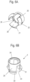
- the intermediate connector 3 comprises, on the side facing away from the clamping element 2, the first thread 31 for fixing the union nut 4 and, on the opposite side, a sleeve-shaped section with a second thread 32, which is designed as an external thread.
- a polygon 30, in particular a hexagon, is integrally formed between the first thread 31 and the second thread 32 in order to rotate the intermediate connector 3 relative to the union nut 4 or another nut 5.
- the half screw connection 1 is shown assembled, and it can be seen that the internal thread 24 of the clamping element 2 is screwed onto the second thread 32 of the intermediate connector.
- the thread 32 of the intermediate connector is screwed into the clamping element 2 so far that the spring bars 20 are supported on an inner side and thus can no longer bend inwards in the assembled position in order to fix the half screw connection 1 to the wall element 10.
- the second thread 32 is preferably screwed in over at least 50% of the length of the spring bars 20, for example between 60 and 90% of the length.
- the nut 5 is also screwed onto the second thread 32, which ensures that the clamping element 2 is clamped in the mounted position.
- the nut 5 is screwed in the direction of the wall element 10 until it is directly or via the interposition of a seal 6, in particular an O-ring, against which the wall element 10 rests.
- the clamping element 2 is pulled out of the opening in the wall element 10 until the projections 21 come into contact with the wall element 10.
- the half screw connection can be fixed to wall elements 10 with a thickness between 1 mm and 10 mm, in particular 2 mm and 5 mm.
- a passage 34 for the elongated object 9 is formed, which is formed in the area of the union nut 4 by the sealing element 8.
- the union nut 4 has a clamping section 41 directed obliquely inwards, so that when the union nut 4 is screwed on, the webs 33 with the sealing element 8 are pressed inwards against the elongated object 9.
- the intermediate connector 3 is shown, in which the polygon 30 is arranged between the first thread 31 and the second thread 32.
- the first thread 31 has a larger diameter than the second thread 32, whereby the cross-sectional contour of the passage 34 is constant.
- clamping element 2 which has the internal thread 24 on a sleeve-shaped section and comprises three spring bars 20, between which recesses 23 are formed.
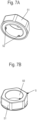
- the nut 5 is shown, which has a polygon 51 on the outer circumference, which surrounds an internal thread 50, which can optionally be designed as a segmented thread.
- Three projections 52 are also formed on the nut 5, which can be inserted into the recesses 23 on the clamping element 2 in order to arrange the clamping element 2 in a rotationally fixed manner when the intermediate connector 3 with the second thread 32 is screwed into the clamping element 2.
- the clamping element 2 is first inserted into the opening on the wall element 10 until the projections 21 are arranged on a rear side of the wall element 10.
- the spring bars 20 are now secured against bending inwards by screwing the intermediate piece 3 with the second thread 32 into the clamping element 2.
- the nut 5 is screwed onto the thread 32 until the clamping element is clamped in the direction of the wall element 10 via the projections 21 and the nut 5 rests directly or indirectly, for example via seals 6, on the wall element 10.
- the half screw connection 1 is thus fixed to the wall element 10 by clamping, whereby the thickness of the wall element 10 can be varied, since the nut 5 is axially adjustable via the threaded connection.
- the assembly can optionally be carried out with pre-assembled cables, although these can also be subsequently inserted into the half screw connection 1.
- the nut 5 is formed separately from the clamping element 2 in order to fix the half screw connection 1 to the wall element 10. It is also possible to form the nut 5 integrally with the clamping element 2.
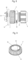
- FIG 8 a modified embodiment is shown in which a modified nut 5' is screwed onto the second thread 32 of the intermediate connector 3. Otherwise, the embodiment corresponds to the first embodiment with the clamping element 2, which is pushed through an opening in the wall element 10 and in which the spring bars 20 are supported on the inside by the second thread 32.
- the nut 5' does not have a polygon on the outer circumference, but is designed as a knurled nut with teeth or fluting arranged on the circumference.
- a thread 50 is provided which is formed from a plurality of inwardly projecting projections 52 which can be screwed onto the second thread 32.
- the nut 5' has a toothing 53 or serration which can be brought into engagement with a rotatable drive tool, which is advantageous for automated or semi-automated assembly.
Landscapes
- Engineering & Computer Science (AREA)
- General Engineering & Computer Science (AREA)
- Mechanical Engineering (AREA)
- Architecture (AREA)
- Civil Engineering (AREA)
- Structural Engineering (AREA)
- Clamps And Clips (AREA)
- Mutual Connection Of Rods And Tubes (AREA)
Applications Claiming Priority (1)
| Application Number | Priority Date | Filing Date | Title |
|---|---|---|---|
| DE102022104790.3A DE102022104790A1 (de) | 2022-03-01 | 2022-03-01 | Halbverschraubung und Verfahren zur Montage einer Halbverschraubung |
Publications (3)
| Publication Number | Publication Date |
|---|---|
| EP4239233A1 EP4239233A1 (de) | 2023-09-06 |
| EP4239233B1 true EP4239233B1 (de) | 2024-12-25 |
| EP4239233C0 EP4239233C0 (de) | 2024-12-25 |
Family
ID=85076133
Family Applications (1)
| Application Number | Title | Priority Date | Filing Date |
|---|---|---|---|
| EP23153326.6A Active EP4239233B1 (de) | 2022-03-01 | 2023-01-25 | Halbverschraubung und verfahren zur montage einer halbverschraubung |
Country Status (4)
| Country | Link |
|---|---|
| EP (1) | EP4239233B1 (pl) |
| DE (1) | DE102022104790A1 (pl) |
| ES (1) | ES3009474T3 (pl) |
| PL (1) | PL4239233T3 (pl) |
Families Citing this family (4)
| Publication number | Priority date | Publication date | Assignee | Title |
|---|---|---|---|---|
| DE102023101848A1 (de) * | 2023-01-25 | 2024-07-25 | CENA-Kunststoff GmbH | Montageanordnung zur Fixierung einer Kabelverbindung, Montagewerkzeug und Verfahren zur Montage einer Kabelverbindung |
| DE102023121437A1 (de) | 2023-08-10 | 2025-02-13 | CENA-Kunststoff GmbH | Überwurfmutter, Montageanordnung, Kabelverschraubung und Verfahren zur Montage einer Kabelverschraubung |
| EP4546582A1 (de) | 2023-10-24 | 2025-04-30 | CENA Kunststoff GmbH | Kabeldurchführung |
| EP4572045A1 (de) | 2023-12-14 | 2025-06-18 | CENA Kunststoff GmbH | Kabeldurchführung |
Family Cites Families (6)
| Publication number | Priority date | Publication date | Assignee | Title |
|---|---|---|---|---|
| US2537183A (en) * | 1949-03-14 | 1951-01-09 | Bloomer Edward James | Coupling connection |
| GB1269499A (en) * | 1968-05-07 | 1972-04-06 | Plastiers Ltd | Pipe connections |
| DE10033911C1 (de) * | 2000-07-12 | 2002-04-04 | Hummel Anton Verwaltung | Anschlussarmatur für längliche Körper mit Spannzange |
| DE202005021582U1 (de) * | 2005-04-08 | 2008-10-16 | Lapp Engineering & Co. | Kabeldurchführung |
| DE202007017765U1 (de) | 2007-12-20 | 2008-03-06 | Anton Hummel Verwaltungs-Gmbh | Anschlussarmatur |
| DE102021106864A1 (de) | 2021-03-19 | 2022-09-22 | CENA-Kunststoff GmbH | Halbverschraubung |
-
2022
- 2022-03-01 DE DE102022104790.3A patent/DE102022104790A1/de active Pending
-
2023
- 2023-01-25 EP EP23153326.6A patent/EP4239233B1/de active Active
- 2023-01-25 PL PL23153326.6T patent/PL4239233T3/pl unknown
- 2023-01-25 ES ES23153326T patent/ES3009474T3/es active Active
Also Published As
| Publication number | Publication date |
|---|---|
| EP4239233A1 (de) | 2023-09-06 |
| DE102022104790A1 (de) | 2023-09-07 |
| PL4239233T3 (pl) | 2025-05-19 |
| ES3009474T3 (en) | 2025-03-27 |
| EP4239233C0 (de) | 2024-12-25 |
Similar Documents
| Publication | Publication Date | Title |
|---|---|---|
| EP4239233B1 (de) | Halbverschraubung und verfahren zur montage einer halbverschraubung | |
| EP3698055B1 (de) | Toleranzausgleichsanordnung | |
| EP3698056B1 (de) | Toleranzausgleichsanordnung | |
| EP1065426B1 (de) | Anschlussarmatur zum Befestigen von länglichen Körpern | |
| EP3717786B1 (de) | Toleranzausgleichsanordnung mit klemmsicherung | |
| EP2481939B1 (de) | Spannschelle | |
| EP4060838A1 (de) | Halbverschraubung | |
| EP2487397A1 (de) | Spannschelle | |
| EP1201941A2 (de) | Schienenanbinder | |
| DE102016108905B4 (de) | Anschlussvorrichtung | |
| WO2020200776A1 (de) | Mehrteiliges verstellelement für eine toleranzausgleichsanordnung | |
| EP2775187B1 (de) | Vorrichtung für eine schlaucharmatur | |
| EP2261519A2 (de) | Schraube zum Befestigen eines ersten Bauteils an einem zweiten Bauteil | |
| DE10107635A1 (de) | Befestigungsvorrichtung zur Festlegung eines Seilzuges | |
| EP3581811A1 (de) | System zur befestigung einer ersten komponente an einer zweiten komponente | |
| EP2115825B1 (de) | Elektrischer steckverbinder | |
| EP2456030B1 (de) | Einseitig einsetzbare Kabelverschraubung | |
| DE102004016599B3 (de) | Steckverbindung mit Winkelarretierung | |
| DE102023205044A1 (de) | Vorrichtung zum Ausgleichen von Toleranzen zwischen zwei miteinander zu verbindenden Bauteilen | |
| DE10200376A1 (de) | Befestigungsvorrichtung | |
| DE102007059329A1 (de) | Steckverbindung für Rohrleitungen | |
| DE102004032053B4 (de) | Rohrschelle mit integriertem Rast-Verschluss | |
| EP2568207A1 (de) | Rohrverbinder | |
| DE19932602C2 (de) | Rohrkupplung | |
| EP3626898B1 (de) | Profilrohrsystem |
Legal Events
| Date | Code | Title | Description |
|---|---|---|---|
| PUAI | Public reference made under article 153(3) epc to a published international application that has entered the european phase |
Free format text: ORIGINAL CODE: 0009012 |
|
| STAA | Information on the status of an ep patent application or granted ep patent |
Free format text: STATUS: THE APPLICATION HAS BEEN PUBLISHED |
|
| AK | Designated contracting states |
Kind code of ref document: A1 Designated state(s): AL AT BE BG CH CY CZ DE DK EE ES FI FR GB GR HR HU IE IS IT LI LT LU LV MC ME MK MT NL NO PL PT RO RS SE SI SK SM TR |
|
| STAA | Information on the status of an ep patent application or granted ep patent |
Free format text: STATUS: REQUEST FOR EXAMINATION WAS MADE |
|
| 17P | Request for examination filed |
Effective date: 20230905 |
|
| RBV | Designated contracting states (corrected) |
Designated state(s): AL AT BE BG CH CY CZ DE DK EE ES FI FR GB GR HR HU IE IS IT LI LT LU LV MC ME MK MT NL NO PL PT RO RS SE SI SK SM TR |
|
| GRAP | Despatch of communication of intention to grant a patent |
Free format text: ORIGINAL CODE: EPIDOSNIGR1 |
|
| STAA | Information on the status of an ep patent application or granted ep patent |
Free format text: STATUS: GRANT OF PATENT IS INTENDED |
|
| RIC1 | Information provided on ipc code assigned before grant |
Ipc: H02G 3/06 20060101ALI20240821BHEP Ipc: F16L 41/14 20060101ALI20240821BHEP Ipc: F16L 37/00 20060101ALI20240821BHEP Ipc: F16L 5/06 20060101AFI20240821BHEP |
|
| INTG | Intention to grant announced |
Effective date: 20240916 |
|
| GRAS | Grant fee paid |
Free format text: ORIGINAL CODE: EPIDOSNIGR3 |
|
| GRAA | (expected) grant |
Free format text: ORIGINAL CODE: 0009210 |
|
| STAA | Information on the status of an ep patent application or granted ep patent |
Free format text: STATUS: THE PATENT HAS BEEN GRANTED |
|
| AK | Designated contracting states |
Kind code of ref document: B1 Designated state(s): AL AT BE BG CH CY CZ DE DK EE ES FI FR GB GR HR HU IE IS IT LI LT LU LV MC ME MK MT NL NO PL PT RO RS SE SI SK SM TR |
|
| REG | Reference to a national code |
Ref country code: GB Ref legal event code: FG4D Free format text: NOT ENGLISH |
|
| REG | Reference to a national code |
Ref country code: CH Ref legal event code: EP |
|
| REG | Reference to a national code |
Ref country code: DE Ref legal event code: R096 Ref document number: 502023000409 Country of ref document: DE |
|
| REG | Reference to a national code |
Ref country code: IE Ref legal event code: FG4D Free format text: LANGUAGE OF EP DOCUMENT: GERMAN |
|
| U01 | Request for unitary effect filed |
Effective date: 20250116 |
|
| U07 | Unitary effect registered |
Designated state(s): AT BE BG DE DK EE FI FR IT LT LU LV MT NL PT RO SE SI Effective date: 20250122 |
|
| U20 | Renewal fee for the european patent with unitary effect paid |
Year of fee payment: 3 Effective date: 20250130 |
|
| REG | Reference to a national code |
Ref country code: ES Ref legal event code: FG2A Ref document number: 3009474 Country of ref document: ES Kind code of ref document: T3 Effective date: 20250327 |
|
| PGFP | Annual fee paid to national office [announced via postgrant information from national office to epo] |
Ref country code: ES Payment date: 20250313 Year of fee payment: 3 |
|
| PGFP | Annual fee paid to national office [announced via postgrant information from national office to epo] |
Ref country code: NO Payment date: 20250120 Year of fee payment: 3 |
|
| PG25 | Lapsed in a contracting state [announced via postgrant information from national office to epo] |
Ref country code: GR Free format text: LAPSE BECAUSE OF FAILURE TO SUBMIT A TRANSLATION OF THE DESCRIPTION OR TO PAY THE FEE WITHIN THE PRESCRIBED TIME-LIMIT Effective date: 20250326 |
|
| PG25 | Lapsed in a contracting state [announced via postgrant information from national office to epo] |
Ref country code: RS Free format text: LAPSE BECAUSE OF FAILURE TO SUBMIT A TRANSLATION OF THE DESCRIPTION OR TO PAY THE FEE WITHIN THE PRESCRIBED TIME-LIMIT Effective date: 20250325 |
|
| PG25 | Lapsed in a contracting state [announced via postgrant information from national office to epo] |
Ref country code: SM Free format text: LAPSE BECAUSE OF FAILURE TO SUBMIT A TRANSLATION OF THE DESCRIPTION OR TO PAY THE FEE WITHIN THE PRESCRIBED TIME-LIMIT Effective date: 20241225 |
|
| PGFP | Annual fee paid to national office [announced via postgrant information from national office to epo] |
Ref country code: PL Payment date: 20250120 Year of fee payment: 3 |
|
| PG25 | Lapsed in a contracting state [announced via postgrant information from national office to epo] |
Ref country code: IS Free format text: LAPSE BECAUSE OF FAILURE TO SUBMIT A TRANSLATION OF THE DESCRIPTION OR TO PAY THE FEE WITHIN THE PRESCRIBED TIME-LIMIT Effective date: 20250425 |
|
| PG25 | Lapsed in a contracting state [announced via postgrant information from national office to epo] |
Ref country code: SK Free format text: LAPSE BECAUSE OF FAILURE TO SUBMIT A TRANSLATION OF THE DESCRIPTION OR TO PAY THE FEE WITHIN THE PRESCRIBED TIME-LIMIT Effective date: 20241225 |
|
| PGFP | Annual fee paid to national office [announced via postgrant information from national office to epo] |
Ref country code: CZ Payment date: 20250120 Year of fee payment: 3 |
|
| PG25 | Lapsed in a contracting state [announced via postgrant information from national office to epo] |
Ref country code: MC Free format text: LAPSE BECAUSE OF FAILURE TO SUBMIT A TRANSLATION OF THE DESCRIPTION OR TO PAY THE FEE WITHIN THE PRESCRIBED TIME-LIMIT Effective date: 20241225 |
|
| PLBE | No opposition filed within time limit |
Free format text: ORIGINAL CODE: 0009261 |
|
| STAA | Information on the status of an ep patent application or granted ep patent |
Free format text: STATUS: NO OPPOSITION FILED WITHIN TIME LIMIT |
|
| 26N | No opposition filed |
Effective date: 20250926 |