EP4239233A1 - Demi-écrou et procédé d'assemblage d'un demi-écrou - Google Patents
Demi-écrou et procédé d'assemblage d'un demi-écrou Download PDFInfo
- Publication number
- EP4239233A1 EP4239233A1 EP23153326.6A EP23153326A EP4239233A1 EP 4239233 A1 EP4239233 A1 EP 4239233A1 EP 23153326 A EP23153326 A EP 23153326A EP 4239233 A1 EP4239233 A1 EP 4239233A1
- Authority
- EP
- European Patent Office
- Prior art keywords
- thread
- nut
- screw connection
- half screw
- connection according
- Prior art date
- Legal status (The legal status is an assumption and is not a legal conclusion. Google has not performed a legal analysis and makes no representation as to the accuracy of the status listed.)
- Pending
Links
Images

Classifications
-
- F—MECHANICAL ENGINEERING; LIGHTING; HEATING; WEAPONS; BLASTING
- F16—ENGINEERING ELEMENTS AND UNITS; GENERAL MEASURES FOR PRODUCING AND MAINTAINING EFFECTIVE FUNCTIONING OF MACHINES OR INSTALLATIONS; THERMAL INSULATION IN GENERAL
- F16L—PIPES; JOINTS OR FITTINGS FOR PIPES; SUPPORTS FOR PIPES, CABLES OR PROTECTIVE TUBING; MEANS FOR THERMAL INSULATION IN GENERAL
- F16L5/00—Devices for use where pipes, cables or protective tubing pass through walls or partitions
- F16L5/02—Sealing
- F16L5/06—Sealing by means of a swivel nut compressing a ring or sleeve
-
- F—MECHANICAL ENGINEERING; LIGHTING; HEATING; WEAPONS; BLASTING
- F16—ENGINEERING ELEMENTS AND UNITS; GENERAL MEASURES FOR PRODUCING AND MAINTAINING EFFECTIVE FUNCTIONING OF MACHINES OR INSTALLATIONS; THERMAL INSULATION IN GENERAL
- F16L—PIPES; JOINTS OR FITTINGS FOR PIPES; SUPPORTS FOR PIPES, CABLES OR PROTECTIVE TUBING; MEANS FOR THERMAL INSULATION IN GENERAL
- F16L37/00—Couplings of the quick-acting type
- F16L37/008—Couplings of the quick-acting type for branching pipes; for joining pipes to walls
-
- F—MECHANICAL ENGINEERING; LIGHTING; HEATING; WEAPONS; BLASTING
- F16—ENGINEERING ELEMENTS AND UNITS; GENERAL MEASURES FOR PRODUCING AND MAINTAINING EFFECTIVE FUNCTIONING OF MACHINES OR INSTALLATIONS; THERMAL INSULATION IN GENERAL
- F16L—PIPES; JOINTS OR FITTINGS FOR PIPES; SUPPORTS FOR PIPES, CABLES OR PROTECTIVE TUBING; MEANS FOR THERMAL INSULATION IN GENERAL
- F16L41/00—Branching pipes; Joining pipes to walls
- F16L41/08—Joining pipes to walls or pipes, the joined pipe axis being perpendicular to the plane of the wall or to the axis of another pipe
- F16L41/14—Joining pipes to walls or pipes, the joined pipe axis being perpendicular to the plane of the wall or to the axis of another pipe by screwing an intermediate part against the inside or outside of the wall
-
- H—ELECTRICITY
- H02—GENERATION; CONVERSION OR DISTRIBUTION OF ELECTRIC POWER
- H02G—INSTALLATION OF ELECTRIC CABLES OR LINES, OR OF COMBINED OPTICAL AND ELECTRIC CABLES OR LINES
- H02G3/00—Installations of electric cables or lines or protective tubing therefor in or on buildings, equivalent structures or vehicles
- H02G3/02—Details
- H02G3/06—Joints for connecting lengths of protective tubing or channels, to each other or to casings, e.g. to distribution boxes; Ensuring electrical continuity in the joint
- H02G3/0616—Joints for connecting tubing to casing
- H02G3/0625—Joints for connecting tubing to casing with means for preventing disengagement of conductors
- H02G3/0675—Joints for connecting tubing to casing with means for preventing disengagement of conductors with bolts operating in a direction parallel to the conductors
Definitions
- the present invention relates to a half screw connection for mounting on an opening of a wall element, with a sleeve-shaped tensioning element on which at least one spring bar is provided with at least one outwardly protruding projection for gripping behind the wall element, and an intermediate connector with a first thread and a second thread. a union nut being screwed onto the first thread.
- the EP 2 225 811 B1 discloses a fitting for attaching hoses or cables to an opening in a wall, in which a clamping element with abutment tongues is inserted into the opening.
- This clamping element has an external thread that is connected to an internal thread of a screw sleeve.
- a sleeve lock is inserted into the tension member to prevent movement of the abutment tabs.
- a union nut is fixed to the screw sleeve.
- the Post-Released DE 10 2021 106 864 discloses a half screw connection which can be attached to an opening in a wall from one side and which has an insertion part with latching hooks which can be supported by a securing element.
- a union nut is fixed to an external thread of the plug-in part, so that the half screw connection can be fixed to the housing wall with just a few components.
- An adaptation to different wall thicknesses is not provided here either.
- the half screw connection according to the invention can be mounted on an opening of a wall element, for example a housing, a cabinet, in particular for the passage of hoses, pipes or cables.
- the half screw connection comprises a sleeve-shaped clamping element with at least one spring bar with at least one radially outwardly protruding projection for gripping behind the wall element, and an intermediate connector with a first thread and a second thread, a union nut being screwed onto the first thread.
- An internal thread is screwed onto the clamping element on the second thread of the intermediate connector, which is designed as an external thread, and the at least one spring bar can be supported on a radially inner side by an end section of the intermediate connector.
- a half screw connection is a cable bushing or cable gland in which a fixing by screwing takes place only on one side of a wall element, usually on the outer side or half of a wall element.
- the tensioning element preferably has the internal thread on a sleeve-shaped section.
- the tensioning element can be slotted in the axial direction in order to be able to be mounted on an elongate object.
- the internal thread can be formed by individual segments, projections or by a complete turn of the thread. The type of internal thread can be adapted to the respective load case.
- a plurality of spring bars preferably extend in the axial direction on the sleeve-shaped section and engage behind the wall element in the mounted position.
- the spring bars can be arranged at a distance from one another via slots or openings. Three spring bars distributed over the circumference can be provided for effective centering.
- a nut is preferably screwed onto the second thread of the intermediate connection piece, which nut can be braced with the tensioning element in the axial direction.
- the nut can be screwed onto the second thread of the intermediate connector until the nut directly or indirectly bears against the wall element and thus pulls the intermediate connector and the tensioning element out of the opening of the wall element in the axial direction until the at least one projection rests against the spring bar on the wall element and is braced.
- an elastic seal can be provided between the nut and the wall element in order to create a seal.
- the nut can be designed with a polygon on the outer circumference or as a knurled nut with corrugations or teeth on the outer circumference. Such a ribbing or toothing can also be driven by a tool in order to be able to effectively assemble the half screw connection.
- a polygon for a tool is integrally formed on the intermediate connector, for example a hexagon or a square, so that during assembly the intermediate connector can be rotated or fixed with a first tool and the nut can be rotated or fixed with a second tool can.
- the polygon can be formed between the first thread and the second thread, which can optionally have a different diameter in order to avoid incorrect assembly. Alternatively, the two threads can also have the same outer diameter.
- a cage can be formed by a plurality of axially protruding webs on the end of the second thread of the intermediate connection piece.
- An annular sealing element made of an elastic material is preferably held on the webs of the cage, which is pressed against an elongate object, such as a hose or cable, for a seal when the union nut is screwed on.
- the sealing of the half-bolt connection can be further improved if a seal is also provided between the polygon and the nut, so that after the nut has been installed, the polygon is screwed onto the nut with a seal interposed.
- the nut and/or the clamping element can have a segmented thread on an inside.
- the thread can optionally be designed in such a way that if a predetermined force is exceeded in axial direction an axial displacement is made possible and only the fine adjustment is done by turning the thread.
- the pattern, the tensioning element and/or the intermediate connector can be produced as injection-moulded parts made of plastic, alternatively they can also be made entirely or partially of metal.
- a sleeve-shaped tensioning element with at least one spring bar with a radially outwardly projecting projection is first inserted through an opening in a wall element, so that the at least one projection engages behind the wall element.
- An external thread of an intermediate connector is then screwed into an internal thread of the tensioning element until the at least one spring bar is at least partially supported on an inside against a radially inward movement.
- a nut is also screwed onto the outer thread of the intermediate connector until the nut bears directly or indirectly on a wall element and prestresses the at least one projection on the at least one spring bar in the axial direction towards the wall element.
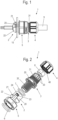
- a half screw 1 is used to fix an elongated object 9, such as a cable, a pipe or a line for implementation in an opening of a wall element 10, such as a switch cabinet or other component.
- the screw half-joint 1 comprises a tensioning element 2, which is inserted through the opening in the wall element 10 with a plurality of spring bars 20 distributed over the circumference.
- the flexible spring bars 20 each have a protruding projection 21 on the radially outer side, which in the mounted position comes to rest on one side of the wall element 10 .
- the spring bars 20 are provided with a starting bevel 22 in the area of the projection 21, which ensures that the spring bars 20 can be bent radially inward when pushed through the opening, in order to then latch behind the opening.
- the clamping element 2 is fixed to an intermediate connector 3 onto which a union nut 4 is screwed on a first thread 31 .
- the elongate object 9 is passed through and fixed by the union nut 4 and the intermediate piece 3 .
- the clamping element 2 has a sleeve-shaped section, which does not have to be completely ring-shaped and can, for example, comprise a slot or a recess.
- An internal thread 24 is formed on the sleeve-shaped section, which is formed by segmented sections or by one or more turns. From the sleeve-like Section the spring bars 20 extend in the axial direction, with openings or recesses 23 being provided between the spring bars 20, so that the spring bars 20 can be pivoted independently of one another.
- the intermediate connector 3 On the side facing away from the clamping element 2, the intermediate connector 3 comprises the first thread 31 for fixing the union nut 4 and on the opposite side a sleeve-shaped section with a second thread 32, which is designed as an external thread.
- a polygon 30 in particular a hexagon, is integrally formed between the first thread 31 and the second thread 32 in order to rotate the intermediate connector 3 relative to the union nut 4 or another nut 5 .
- On the first thread 31 a cage made up of a plurality of webs 33 is formed in the axial direction, into which an annular sealing element 8 is inserted. By unscrewing the union nut 4, the sealing element 8 can be pressed against the elongate object 9 for sealing.
- the half screw connection 1 also includes a nut 5 which can be screwed onto the second thread 32 of the intermediate connection piece 3 .
- a seal 7 is provided between the nut 5 and the polygon 30, which is designed, for example, as an O-ring.
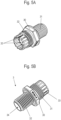
- the half screw connection 1 is shown assembled, and it can be seen that the internal thread of the 24 of the clamping element 2 is screwed onto the second thread 32 of the intermediate connection piece.
- the thread 32 of the intermediate connector is screwed into the tensioning element 2 to such an extent that the spring bars 20 are supported on an inner side and can therefore no longer bend inwards in the mounted position in order to fix the screw half connection 1 to the wall element 10 .
- the second thread 32 is preferably screwed in over at least 50% of the length of the spring bars 20, for example between 60 and 90% of the length.
- the nut 5 is also screwed onto the second thread 32 and ensures that the clamping element 2 is braced in the assembled position.
- the nut 5 is screwed in the direction of the wall element 10 until it rests against the wall element 10 directly or via the interposition of a seal 6, in particular an O-ring.
- the clamping element 2 is pulled out of the opening in the wall element 10 by screwing the nut 5 until the projections 21 on the wall element 10 come to the plant.
- the half screw connection can be fixed to wall elements 10 with a thickness between 1 mm and 10 mm, in particular 2 mm and 5 mm.
- a passage 34 for the elongate object 9 is formed in the intermediate connector 3 and is formed by the sealing element 8 in the region of the union nut 4 .
- the union nut 4 has a clamping section 41 directed obliquely inward, so that when the union nut 4 is screwed on, the webs 33 with the sealing element 8 are pressed inward against the elongate object 9 .
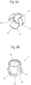
- the intermediate connector 3 is shown, in which the polygon 30 is arranged between the first thread 31 and the second thread 32 .
- the first thread 31 has a larger diameter than the second thread 32, the cross-sectional contour of the bushing 34 being constant.
- clamping element 2 which has the internal thread 24 on a sleeve-shaped section and comprises three spring bars 20, between which recesses 23 are formed.
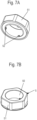
- the nut 5 is shown, which has a polygon 51 on the outer circumference, which surrounds an internal thread 50, which can optionally be designed as a segmented thread. Also formed on the nut 5 are three projections 52 which can be inserted into the recesses 23 on the clamping element 2 in order to arrange the clamping element 2 in a rotationally fixed manner when the intermediate connector 3 is screwed into the clamping element 2 with the second thread 32 .
- the clamping element 2 is first inserted into the opening on the wall element 10 until the projections 21 are arranged on a rear side of the wall element 10 .
- the spring bars 20 are now secured against inward bending by the intermediate connector 3 being screwed into the clamping element 2 with the second thread 32 .
- the nut 5 is screwed onto the thread 32 until the clamping element is clamped in the direction of the wall element 10 via the projections 21 and the nut 5 directly or indirectly, for example via seals 6, on which wall element 10 rests.
- the half screw connection 1 is fixed to the wall element 10 by bracing, the thickness of the wall element 10 being able to be variable, since the nut 5 can be adjusted axially via the threaded connection.
- the assembly can optionally be carried out with pre-assembled cables, which can also be plugged into the screw half 1 later.
- the nut 5 is formed separately from the tensioning element 2 in order to fix the half screw connection 1 to the wall element 10 . It is also possible to form the nut 5 integrally with the tensioning element 2 .
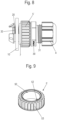
- FIG 8 a modified embodiment is shown, in which a modified nut 5' is screwed onto the second thread 32 of the intermediate connector 3.
- the exemplary embodiment corresponds to the first exemplary embodiment with the clamping element 2, which is pushed through an opening in the wall element 10 and in which the spring bars 20 are supported on the inside by the second thread 32.
- the nut 5' does not have a polygon on the outer circumference, but is designed as a knurled nut with teeth or corrugations arranged on the circumference.
- FIG 9 the nut 5' is shown in detail.
- a thread 50 is provided on an inner circumference, which is formed from a plurality of inwardly projecting projections 52 which can be screwed onto the second thread 32 .
- the nut 5' has teeth 53 or serrations which can be brought into engagement with a rotatable drive tool, which is advantageous for automated or semi-automated assembly.
Landscapes
- Engineering & Computer Science (AREA)
- General Engineering & Computer Science (AREA)
- Mechanical Engineering (AREA)
- Architecture (AREA)
- Civil Engineering (AREA)
- Structural Engineering (AREA)
- Mutual Connection Of Rods And Tubes (AREA)
- Clamps And Clips (AREA)
Applications Claiming Priority (1)
| Application Number | Priority Date | Filing Date | Title |
|---|---|---|---|
| DE102022104790.3A DE102022104790A1 (de) | 2022-03-01 | 2022-03-01 | Halbverschraubung und Verfahren zur Montage einer Halbverschraubung |
Publications (1)
| Publication Number | Publication Date |
|---|---|
| EP4239233A1 true EP4239233A1 (fr) | 2023-09-06 |
Family
ID=85076133
Family Applications (1)
| Application Number | Title | Priority Date | Filing Date |
|---|---|---|---|
| EP23153326.6A Pending EP4239233A1 (fr) | 2022-03-01 | 2023-01-25 | Demi-écrou et procédé d'assemblage d'un demi-écrou |
Country Status (2)
| Country | Link |
|---|---|
| EP (1) | EP4239233A1 (fr) |
| DE (1) | DE102022104790A1 (fr) |
Citations (6)
| Publication number | Priority date | Publication date | Assignee | Title |
|---|---|---|---|---|
| US2537183A (en) * | 1949-03-14 | 1951-01-09 | Bloomer Edward James | Coupling connection |
| GB1269499A (en) * | 1968-05-07 | 1972-04-06 | Plastiers Ltd | Pipe connections |
| US20020006309A1 (en) * | 2000-07-12 | 2002-01-17 | Anton Hummel Verwaltungs Gmbh | Connection fitting with clamping collet for elongated bodies |
| EP1710886A1 (fr) * | 2005-04-08 | 2006-10-11 | Lapp Engineering & Co | Traversée de câble |
| EP2225811B1 (fr) | 2007-12-20 | 2011-05-18 | Hummel Ag | Raccord |
| DE102021106864A1 (de) | 2021-03-19 | 2022-09-22 | CENA-Kunststoff GmbH | Halbverschraubung |
-
2022
- 2022-03-01 DE DE102022104790.3A patent/DE102022104790A1/de active Pending
-
2023
- 2023-01-25 EP EP23153326.6A patent/EP4239233A1/fr active Pending
Patent Citations (6)
| Publication number | Priority date | Publication date | Assignee | Title |
|---|---|---|---|---|
| US2537183A (en) * | 1949-03-14 | 1951-01-09 | Bloomer Edward James | Coupling connection |
| GB1269499A (en) * | 1968-05-07 | 1972-04-06 | Plastiers Ltd | Pipe connections |
| US20020006309A1 (en) * | 2000-07-12 | 2002-01-17 | Anton Hummel Verwaltungs Gmbh | Connection fitting with clamping collet for elongated bodies |
| EP1710886A1 (fr) * | 2005-04-08 | 2006-10-11 | Lapp Engineering & Co | Traversée de câble |
| EP2225811B1 (fr) | 2007-12-20 | 2011-05-18 | Hummel Ag | Raccord |
| DE102021106864A1 (de) | 2021-03-19 | 2022-09-22 | CENA-Kunststoff GmbH | Halbverschraubung |
Also Published As
| Publication number | Publication date |
|---|---|
| DE102022104790A1 (de) | 2023-09-07 |
Similar Documents
| Publication | Publication Date | Title |
|---|---|---|
| DE102011010655B3 (de) | Spannschelle | |
| EP3698056B1 (fr) | Système de compensation de tolérances | |
| EP2225811B1 (fr) | Raccord | |
| EP1201941A2 (fr) | Dispositif d'attachement pour rail | |
| EP2481939B1 (fr) | collier de serrage | |
| EP1541878B1 (fr) | Système de fixation | |
| DE102011005598A1 (de) | Befestigungsvorrichtung zur Anordnung an einer Montageschiene | |
| EP4060838A1 (fr) | Presse-étoupe | |
| DE102012221228A1 (de) | Toleranzausgleichsvorrichtung | |
| EP2218924A2 (fr) | Dispositif de fixation destiné à l'agencement sur un rail de montage | |
| AT410012B (de) | Rückhaltevorrichtung für ein verbindungselement | |
| EP2261519A2 (fr) | Vis destinée à la fixation d'un premier composant sur un second composant | |
| DE19631656A1 (de) | Klemme | |
| EP0908637A2 (fr) | Ecrou et collier de serrage | |
| WO2020200776A1 (fr) | Élément de réglage en plusieurs parties pour un agencement de compensation de tolérances | |
| DE10315690B4 (de) | Befestigungsvorrichtung für eine Anhängevorrichtung an einem Längsträger eines Kraftfahrzeuges | |
| EP2456030B1 (fr) | Vissage de câble insérable sur un côté | |
| DE3115040A1 (de) | "formschluessig setzbarer duebel" | |
| EP3581811A1 (fr) | Système de fixation d'un premier composant sur un second composant | |
| DE10200376A1 (de) | Befestigungsvorrichtung | |
| EP4239233A1 (fr) | Demi-écrou et procédé d'assemblage d'un demi-écrou | |
| EP3064785A1 (fr) | Dispositif de fixation sur un composant | |
| DE19730269C2 (de) | Vorrichtung zum Befestigen eines ersten Teils mit einem zweiten Teil | |
| CH669438A5 (en) | Clip and anchoring part | |
| DE102004032053B4 (de) | Rohrschelle mit integriertem Rast-Verschluss |
Legal Events
| Date | Code | Title | Description |
|---|---|---|---|
| PUAI | Public reference made under article 153(3) epc to a published international application that has entered the european phase |
Free format text: ORIGINAL CODE: 0009012 |
|
| STAA | Information on the status of an ep patent application or granted ep patent |
Free format text: STATUS: THE APPLICATION HAS BEEN PUBLISHED |
|
| AK | Designated contracting states |
Kind code of ref document: A1 Designated state(s): AL AT BE BG CH CY CZ DE DK EE ES FI FR GB GR HR HU IE IS IT LI LT LU LV MC ME MK MT NL NO PL PT RO RS SE SI SK SM TR |
|
| STAA | Information on the status of an ep patent application or granted ep patent |
Free format text: STATUS: REQUEST FOR EXAMINATION WAS MADE |
|
| 17P | Request for examination filed |
Effective date: 20230905 |
|
| RBV | Designated contracting states (corrected) |
Designated state(s): AL AT BE BG CH CY CZ DE DK EE ES FI FR GB GR HR HU IE IS IT LI LT LU LV MC ME MK MT NL NO PL PT RO RS SE SI SK SM TR |