EP4239233A1 - Half screw and method for assembling a half screw - Google Patents
Half screw and method for assembling a half screw Download PDFInfo
- Publication number
- EP4239233A1 EP4239233A1 EP23153326.6A EP23153326A EP4239233A1 EP 4239233 A1 EP4239233 A1 EP 4239233A1 EP 23153326 A EP23153326 A EP 23153326A EP 4239233 A1 EP4239233 A1 EP 4239233A1
- Authority
- EP
- European Patent Office
- Prior art keywords
- thread
- nut
- screw connection
- half screw
- connection according
- Prior art date
- Legal status (The legal status is an assumption and is not a legal conclusion. Google has not performed a legal analysis and makes no representation as to the accuracy of the status listed.)
- Pending
Links
Images

Classifications
-
- F—MECHANICAL ENGINEERING; LIGHTING; HEATING; WEAPONS; BLASTING
- F16—ENGINEERING ELEMENTS AND UNITS; GENERAL MEASURES FOR PRODUCING AND MAINTAINING EFFECTIVE FUNCTIONING OF MACHINES OR INSTALLATIONS; THERMAL INSULATION IN GENERAL
- F16L—PIPES; JOINTS OR FITTINGS FOR PIPES; SUPPORTS FOR PIPES, CABLES OR PROTECTIVE TUBING; MEANS FOR THERMAL INSULATION IN GENERAL
- F16L5/00—Devices for use where pipes, cables or protective tubing pass through walls or partitions
- F16L5/02—Sealing
- F16L5/06—Sealing by means of a swivel nut compressing a ring or sleeve
-
- F—MECHANICAL ENGINEERING; LIGHTING; HEATING; WEAPONS; BLASTING
- F16—ENGINEERING ELEMENTS AND UNITS; GENERAL MEASURES FOR PRODUCING AND MAINTAINING EFFECTIVE FUNCTIONING OF MACHINES OR INSTALLATIONS; THERMAL INSULATION IN GENERAL
- F16L—PIPES; JOINTS OR FITTINGS FOR PIPES; SUPPORTS FOR PIPES, CABLES OR PROTECTIVE TUBING; MEANS FOR THERMAL INSULATION IN GENERAL
- F16L37/00—Couplings of the quick-acting type
- F16L37/008—Couplings of the quick-acting type for branching pipes; for joining pipes to walls
-
- F—MECHANICAL ENGINEERING; LIGHTING; HEATING; WEAPONS; BLASTING
- F16—ENGINEERING ELEMENTS AND UNITS; GENERAL MEASURES FOR PRODUCING AND MAINTAINING EFFECTIVE FUNCTIONING OF MACHINES OR INSTALLATIONS; THERMAL INSULATION IN GENERAL
- F16L—PIPES; JOINTS OR FITTINGS FOR PIPES; SUPPORTS FOR PIPES, CABLES OR PROTECTIVE TUBING; MEANS FOR THERMAL INSULATION IN GENERAL
- F16L41/00—Branching pipes; Joining pipes to walls
- F16L41/08—Joining pipes to walls or pipes, the joined pipe axis being perpendicular to the plane of the wall or to the axis of another pipe
- F16L41/14—Joining pipes to walls or pipes, the joined pipe axis being perpendicular to the plane of the wall or to the axis of another pipe by screwing an intermediate part against the inside or outside of the wall
-
- H—ELECTRICITY
- H02—GENERATION; CONVERSION OR DISTRIBUTION OF ELECTRIC POWER
- H02G—INSTALLATION OF ELECTRIC CABLES OR LINES, OR OF COMBINED OPTICAL AND ELECTRIC CABLES OR LINES
- H02G3/00—Installations of electric cables or lines or protective tubing therefor in or on buildings, equivalent structures or vehicles
- H02G3/02—Details
- H02G3/06—Joints for connecting lengths of protective tubing or channels, to each other or to casings, e.g. to distribution boxes; Ensuring electrical continuity in the joint
- H02G3/0616—Joints for connecting tubing to casing
- H02G3/0625—Joints for connecting tubing to casing with means for preventing disengagement of conductors
- H02G3/0675—Joints for connecting tubing to casing with means for preventing disengagement of conductors with bolts operating in a direction parallel to the conductors
Definitions
- the present invention relates to a half screw connection for mounting on an opening of a wall element, with a sleeve-shaped tensioning element on which at least one spring bar is provided with at least one outwardly protruding projection for gripping behind the wall element, and an intermediate connector with a first thread and a second thread. a union nut being screwed onto the first thread.
- the EP 2 225 811 B1 discloses a fitting for attaching hoses or cables to an opening in a wall, in which a clamping element with abutment tongues is inserted into the opening.
- This clamping element has an external thread that is connected to an internal thread of a screw sleeve.
- a sleeve lock is inserted into the tension member to prevent movement of the abutment tabs.
- a union nut is fixed to the screw sleeve.
- the Post-Released DE 10 2021 106 864 discloses a half screw connection which can be attached to an opening in a wall from one side and which has an insertion part with latching hooks which can be supported by a securing element.
- a union nut is fixed to an external thread of the plug-in part, so that the half screw connection can be fixed to the housing wall with just a few components.
- An adaptation to different wall thicknesses is not provided here either.
- the half screw connection according to the invention can be mounted on an opening of a wall element, for example a housing, a cabinet, in particular for the passage of hoses, pipes or cables.
- the half screw connection comprises a sleeve-shaped clamping element with at least one spring bar with at least one radially outwardly protruding projection for gripping behind the wall element, and an intermediate connector with a first thread and a second thread, a union nut being screwed onto the first thread.
- An internal thread is screwed onto the clamping element on the second thread of the intermediate connector, which is designed as an external thread, and the at least one spring bar can be supported on a radially inner side by an end section of the intermediate connector.
- a half screw connection is a cable bushing or cable gland in which a fixing by screwing takes place only on one side of a wall element, usually on the outer side or half of a wall element.
- the tensioning element preferably has the internal thread on a sleeve-shaped section.
- the tensioning element can be slotted in the axial direction in order to be able to be mounted on an elongate object.
- the internal thread can be formed by individual segments, projections or by a complete turn of the thread. The type of internal thread can be adapted to the respective load case.
- a plurality of spring bars preferably extend in the axial direction on the sleeve-shaped section and engage behind the wall element in the mounted position.
- the spring bars can be arranged at a distance from one another via slots or openings. Three spring bars distributed over the circumference can be provided for effective centering.
- a nut is preferably screwed onto the second thread of the intermediate connection piece, which nut can be braced with the tensioning element in the axial direction.
- the nut can be screwed onto the second thread of the intermediate connector until the nut directly or indirectly bears against the wall element and thus pulls the intermediate connector and the tensioning element out of the opening of the wall element in the axial direction until the at least one projection rests against the spring bar on the wall element and is braced.
- an elastic seal can be provided between the nut and the wall element in order to create a seal.
- the nut can be designed with a polygon on the outer circumference or as a knurled nut with corrugations or teeth on the outer circumference. Such a ribbing or toothing can also be driven by a tool in order to be able to effectively assemble the half screw connection.
- a polygon for a tool is integrally formed on the intermediate connector, for example a hexagon or a square, so that during assembly the intermediate connector can be rotated or fixed with a first tool and the nut can be rotated or fixed with a second tool can.
- the polygon can be formed between the first thread and the second thread, which can optionally have a different diameter in order to avoid incorrect assembly. Alternatively, the two threads can also have the same outer diameter.
- a cage can be formed by a plurality of axially protruding webs on the end of the second thread of the intermediate connection piece.
- An annular sealing element made of an elastic material is preferably held on the webs of the cage, which is pressed against an elongate object, such as a hose or cable, for a seal when the union nut is screwed on.
- the sealing of the half-bolt connection can be further improved if a seal is also provided between the polygon and the nut, so that after the nut has been installed, the polygon is screwed onto the nut with a seal interposed.
- the nut and/or the clamping element can have a segmented thread on an inside.
- the thread can optionally be designed in such a way that if a predetermined force is exceeded in axial direction an axial displacement is made possible and only the fine adjustment is done by turning the thread.
- the pattern, the tensioning element and/or the intermediate connector can be produced as injection-moulded parts made of plastic, alternatively they can also be made entirely or partially of metal.
- a sleeve-shaped tensioning element with at least one spring bar with a radially outwardly projecting projection is first inserted through an opening in a wall element, so that the at least one projection engages behind the wall element.
- An external thread of an intermediate connector is then screwed into an internal thread of the tensioning element until the at least one spring bar is at least partially supported on an inside against a radially inward movement.
- a nut is also screwed onto the outer thread of the intermediate connector until the nut bears directly or indirectly on a wall element and prestresses the at least one projection on the at least one spring bar in the axial direction towards the wall element.
- a half screw 1 is used to fix an elongated object 9, such as a cable, a pipe or a line for implementation in an opening of a wall element 10, such as a switch cabinet or other component.
- the screw half-joint 1 comprises a tensioning element 2, which is inserted through the opening in the wall element 10 with a plurality of spring bars 20 distributed over the circumference.
- the flexible spring bars 20 each have a protruding projection 21 on the radially outer side, which in the mounted position comes to rest on one side of the wall element 10 .
- the spring bars 20 are provided with a starting bevel 22 in the area of the projection 21, which ensures that the spring bars 20 can be bent radially inward when pushed through the opening, in order to then latch behind the opening.
- the clamping element 2 is fixed to an intermediate connector 3 onto which a union nut 4 is screwed on a first thread 31 .
- the elongate object 9 is passed through and fixed by the union nut 4 and the intermediate piece 3 .
- the clamping element 2 has a sleeve-shaped section, which does not have to be completely ring-shaped and can, for example, comprise a slot or a recess.
- An internal thread 24 is formed on the sleeve-shaped section, which is formed by segmented sections or by one or more turns. From the sleeve-like Section the spring bars 20 extend in the axial direction, with openings or recesses 23 being provided between the spring bars 20, so that the spring bars 20 can be pivoted independently of one another.
- the intermediate connector 3 On the side facing away from the clamping element 2, the intermediate connector 3 comprises the first thread 31 for fixing the union nut 4 and on the opposite side a sleeve-shaped section with a second thread 32, which is designed as an external thread.
- a polygon 30 in particular a hexagon, is integrally formed between the first thread 31 and the second thread 32 in order to rotate the intermediate connector 3 relative to the union nut 4 or another nut 5 .
- On the first thread 31 a cage made up of a plurality of webs 33 is formed in the axial direction, into which an annular sealing element 8 is inserted. By unscrewing the union nut 4, the sealing element 8 can be pressed against the elongate object 9 for sealing.
- the half screw connection 1 also includes a nut 5 which can be screwed onto the second thread 32 of the intermediate connection piece 3 .
- a seal 7 is provided between the nut 5 and the polygon 30, which is designed, for example, as an O-ring.
- the half screw connection 1 is shown assembled, and it can be seen that the internal thread of the 24 of the clamping element 2 is screwed onto the second thread 32 of the intermediate connection piece.
- the thread 32 of the intermediate connector is screwed into the tensioning element 2 to such an extent that the spring bars 20 are supported on an inner side and can therefore no longer bend inwards in the mounted position in order to fix the screw half connection 1 to the wall element 10 .
- the second thread 32 is preferably screwed in over at least 50% of the length of the spring bars 20, for example between 60 and 90% of the length.
- the nut 5 is also screwed onto the second thread 32 and ensures that the clamping element 2 is braced in the assembled position.
- the nut 5 is screwed in the direction of the wall element 10 until it rests against the wall element 10 directly or via the interposition of a seal 6, in particular an O-ring.
- the clamping element 2 is pulled out of the opening in the wall element 10 by screwing the nut 5 until the projections 21 on the wall element 10 come to the plant.
- the half screw connection can be fixed to wall elements 10 with a thickness between 1 mm and 10 mm, in particular 2 mm and 5 mm.
- a passage 34 for the elongate object 9 is formed in the intermediate connector 3 and is formed by the sealing element 8 in the region of the union nut 4 .
- the union nut 4 has a clamping section 41 directed obliquely inward, so that when the union nut 4 is screwed on, the webs 33 with the sealing element 8 are pressed inward against the elongate object 9 .
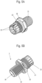
- the intermediate connector 3 is shown, in which the polygon 30 is arranged between the first thread 31 and the second thread 32 .
- the first thread 31 has a larger diameter than the second thread 32, the cross-sectional contour of the bushing 34 being constant.
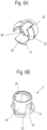
- clamping element 2 which has the internal thread 24 on a sleeve-shaped section and comprises three spring bars 20, between which recesses 23 are formed.
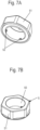
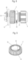
- the nut 5 is shown, which has a polygon 51 on the outer circumference, which surrounds an internal thread 50, which can optionally be designed as a segmented thread. Also formed on the nut 5 are three projections 52 which can be inserted into the recesses 23 on the clamping element 2 in order to arrange the clamping element 2 in a rotationally fixed manner when the intermediate connector 3 is screwed into the clamping element 2 with the second thread 32 .
- the clamping element 2 is first inserted into the opening on the wall element 10 until the projections 21 are arranged on a rear side of the wall element 10 .
- the spring bars 20 are now secured against inward bending by the intermediate connector 3 being screwed into the clamping element 2 with the second thread 32 .
- the nut 5 is screwed onto the thread 32 until the clamping element is clamped in the direction of the wall element 10 via the projections 21 and the nut 5 directly or indirectly, for example via seals 6, on which wall element 10 rests.
- the half screw connection 1 is fixed to the wall element 10 by bracing, the thickness of the wall element 10 being able to be variable, since the nut 5 can be adjusted axially via the threaded connection.
- the assembly can optionally be carried out with pre-assembled cables, which can also be plugged into the screw half 1 later.
- the nut 5 is formed separately from the tensioning element 2 in order to fix the half screw connection 1 to the wall element 10 . It is also possible to form the nut 5 integrally with the tensioning element 2 .
- FIG 8 a modified embodiment is shown, in which a modified nut 5' is screwed onto the second thread 32 of the intermediate connector 3.
- the exemplary embodiment corresponds to the first exemplary embodiment with the clamping element 2, which is pushed through an opening in the wall element 10 and in which the spring bars 20 are supported on the inside by the second thread 32.
- the nut 5' does not have a polygon on the outer circumference, but is designed as a knurled nut with teeth or corrugations arranged on the circumference.
- FIG 9 the nut 5' is shown in detail.
- a thread 50 is provided on an inner circumference, which is formed from a plurality of inwardly projecting projections 52 which can be screwed onto the second thread 32 .
- the nut 5' has teeth 53 or serrations which can be brought into engagement with a rotatable drive tool, which is advantageous for automated or semi-automated assembly.
Abstract
Eine Halbverschraubung (1) zur Montage an einer Öffnung eines Wandelemente (10) umfasst ein hülsenförmiges Spannelement (2), an dem mindestens ein Federsteg (20) mit mindestens einem nach außen hervorstehenden Vorsprung (21) zum Hintergreifen des Wandelementes (10) vorgesehen ist, und einen Zwischenstutzen (3) mit einem ersten Gewinde (31) und einem zweiten Gewinde (32), wobei an dem ersten Gewinde (31) eine Überwurfmutter (4) aufgeschraubt ist, wobei das zweite Gewinde (32) des Zwischenstutzens (3) als Außengewinde ausgebildet ist und auf ein Innengewinde (24) an dem Spannelement (2) aufgeschraubt ist und der mindestens eine Federsteg (20) durch einen Endabschnitt des Zwischenstutzens (3) an einer radial inneren Seite abstützbar ist. Ferner betrifft die Erfindung ein Verfahren zur Montage einer Halbverschraubung (1).

Description
Die vorliegende Erfindung betrifft eine Halbverschraubung zur Montage an einer Öffnung eines Wandelementes, mit einem hülsenförmigen Spannelement, an dem mindestens ein Federsteg mit mindestens einem nach außen hervorstehenden Vorsprung zum Hintergreifen des Wandelementes vorgesehen ist, und einem Zwischenstutzen mit einem ersten Gewinde und einem zweiten Gewinde, wobei an dem ersten Gewinde eine Überwurfmutter aufgeschraubt ist.The present invention relates to a half screw connection for mounting on an opening of a wall element, with a sleeve-shaped tensioning element on which at least one spring bar is provided with at least one outwardly protruding projection for gripping behind the wall element, and an intermediate connector with a first thread and a second thread. a union nut being screwed onto the first thread.
Die
Die nachveröffentlichte
Es ist daher Aufgabe der vorliegenden Erfindung, eine Halbverschraubung und ein Verfahren zur Montage einer Halbverschraubung zu schaffen, die eine effektive Montage gewährleisten und eine Anpassung an unterschiedliche Wanddicken ermöglichen.It is therefore the object of the present invention to create a screw half and a method for assembling a screw half which ensure effective assembly and allow adaptation to different wall thicknesses.
Diese Aufgabe wird mit einer Halbverschraubung mit den Merkmalen des Anspruches 1 sowie einem Verfahren mit den Merkmalen des Anspruches 12 gelöst.This object is achieved with a half screw connection having the features of
Die erfindungsgemäße Halbverschraubung kann an einer Öffnung eines Wandelementes montiert werden, beispielsweise eines Gehäuses, eines Schrankes, insbesondere zur Durchführung von Schläuchen, Rohren oder Kabeln. Die Halbverschraubung umfasst ein hülsenförmiges Spannelement mit mindestens einem Federsteg mit mindestens einem nach radial nach außen hervorstehenden Vorsprung zum Hintergreifen des Wandelementes, und einen Zwischenstutzen mit einem ersten Gewinde und einem zweiten Gewinde, wobei an dem ersten Gewinde eine Überwurfmutter aufgeschraubt ist. An dem zweiten Gewinde des Zwischenstutzens, das als Außengewinde ausgebildet ist, ist ein Innengewinde an dem Spannelement aufgeschraubt, und der mindestens eine Federsteg ist durch einen Endabschnitt des Zwischenstutzens an einer radial inneren Seite abstützbar. Dadurch kann die Einstecktiefe des Zwischenstutzens in das Spannelement flexibel angepasst werden, je nachdem, wie weit das Innengewinde des Zwischenstutzens in das Spannelement eingeschraubt wird. Dies ermöglicht eine einfache Anpassung an unterschiedliche Wanddicken des Wandelementes und sorgt zudem für eine einfache Montage der Halbverschraubung, da der Zwischenstutzen auf einer Seite in das Spannelement eingeschraubt ist und auf der gegenüberliegenden Seite zur Fixierung der Überwurfmutter dient. Eine Halbverschraubung ist dabei eine Kabeldurchführung oder Kabelverschraubung, bei der nur auf einer Seite eines Wandelementes eine Fixierung durch Verschrauben erfolgt, in der Regel an der äußeren Seite oder Hälfte eines Wandelementes.The half screw connection according to the invention can be mounted on an opening of a wall element, for example a housing, a cabinet, in particular for the passage of hoses, pipes or cables. The half screw connection comprises a sleeve-shaped clamping element with at least one spring bar with at least one radially outwardly protruding projection for gripping behind the wall element, and an intermediate connector with a first thread and a second thread, a union nut being screwed onto the first thread. An internal thread is screwed onto the clamping element on the second thread of the intermediate connector, which is designed as an external thread, and the at least one spring bar can be supported on a radially inner side by an end section of the intermediate connector. As a result, the insertion depth of the intermediate connection piece into the clamping element can be flexibly adjusted, depending on how far the internal thread of the intermediate connection piece is screwed into the clamping element. This enables easy adaptation to different wall thicknesses of the wall element and also ensures easy assembly of the half screw connection, since the intermediate connector is screwed into the clamping element on one side and is used to fix the union nut on the opposite side. A half screw connection is a cable bushing or cable gland in which a fixing by screwing takes place only on one side of a wall element, usually on the outer side or half of a wall element.
Vorzugsweise weist das Spannelement an einem hülsenförmigen Abschnitt das Innengewinde auf. Dabei kann das Spannelement in axiale Richtung geschlitzt ausgebildet sein, um auf einen länglichen Gegenstand montiert werden zu können. Das Innengewinde kann dabei durch einzelne Segmente, Vorsprünge oder durch eine vollständige Gewindewindung gebildet sein. Die Art des Innengewindes kann an den jeweiligen Belastungsfall angepasst sein.The tensioning element preferably has the internal thread on a sleeve-shaped section. In this case, the tensioning element can be slotted in the axial direction in order to be able to be mounted on an elongate object. The internal thread can be formed by individual segments, projections or by a complete turn of the thread. The type of internal thread can be adapted to the respective load case.
An dem hülsenförmigen Abschnitt erstrecken sich vorzugsweise mehrere Federstege in axiale Richtung, die in der montierten Position das Wandelement hintergreifen. Die Federstege können dabei über Schlitze oder Öffnungen beabstandet voneinander angeordnet sein. Für eine effektive Zentrierung können drei Federstege über den Umfang verteilt vorgesehen sein.A plurality of spring bars preferably extend in the axial direction on the sleeve-shaped section and engage behind the wall element in the mounted position. The spring bars can be arranged at a distance from one another via slots or openings. Three spring bars distributed over the circumference can be provided for effective centering.
Zur Fixierung der Halbverschraubung an dem Wandelement ist vorzugsweise auf das zweite Gewinde des Zwischenstutzens eine Mutter aufgeschraubt, die in axiale Richtung mit dem Spannelement verspannbar ist. Nach einer Sicherung des mindestens einen Federsteges gegen eine Durchbiegung radial nach innen kann die Mutter so weit auf das zweite Gewinde des Zwischenstutzens aufgeschraubt werden, bis die Mutter unmittelbar oder mittelbar an dem Wandelement anliegt und somit den Zwischenstutzen und das Spannelement in axiale Richtung aus der Öffnung des Wandelementes herauszieht, bis der mindestens eine Vorsprung an dem Federsteg an dem Wandelement anliegt und verspannt ist. Dies sorgt für eine stabile Fixierung der Halbverschraubung. Optional kann dabei zwischen der Mutter und dem Wandelement eine elastische Dichtung vorgesehen sein, um eine Abdichtung zu bewirken. Die Mutter kann am äußeren Umfang mit einem Mehrkant ausgebildet sein oder als Rändelmutter, bei der am äußeren Umfang eine Riffelung oder Verzahnung vorgesehen ist. Eine solche Riffelung oder Verzahnung lässt sich auch durch ein Werkzeug antreiben, um die Halbverschraubung effektiv montieren zu können.In order to fix the half screw connection to the wall element, a nut is preferably screwed onto the second thread of the intermediate connection piece, which nut can be braced with the tensioning element in the axial direction. After a backup of the at least one spring bar against deflection radially inwards, the nut can be screwed onto the second thread of the intermediate connector until the nut directly or indirectly bears against the wall element and thus pulls the intermediate connector and the tensioning element out of the opening of the wall element in the axial direction until the at least one projection rests against the spring bar on the wall element and is braced. This ensures a stable fixation of the half screw connection. Optionally, an elastic seal can be provided between the nut and the wall element in order to create a seal. The nut can be designed with a polygon on the outer circumference or as a knurled nut with corrugations or teeth on the outer circumference. Such a ribbing or toothing can also be driven by a tool in order to be able to effectively assemble the half screw connection.
In einer weiteren Ausgestaltung ist an dem Zwischenstutzen integral ein Mehrkant für ein Werkzeug ausgebildet, beispielsweise ein Sechskant oder ein Vierkant, so dass bei der Montage mit einem ersten Werkzeug der Zwischenstutzen gedreht oder fixiert werden kann und mit einem zweiten Werkzeug die Mutter gedreht oder fixiert werden kann. Der Mehrkant kann dabei zwischen dem ersten Gewinde und dem zweiten Gewinde ausgebildet sein, die optional einen unterschiedlichen Durchmesser aufweisen können, um eine Fehlmontage zu vermeiden. Alternativ können die beiden Gewinde auch den gleichen Außendurchmesser besitzen.In a further embodiment, a polygon for a tool is integrally formed on the intermediate connector, for example a hexagon or a square, so that during assembly the intermediate connector can be rotated or fixed with a first tool and the nut can be rotated or fixed with a second tool can. The polygon can be formed between the first thread and the second thread, which can optionally have a different diameter in order to avoid incorrect assembly. Alternatively, the two threads can also have the same outer diameter.
Um eine verbesserte Abdichtung mit wenig Bauteilen zu erreichen, kann an dem zweiten Gewinde des Zwischenstutzens endseitig ein Käfig durch mehrere axial hervorstehende Stege gebildet sein. An den Stegen des Käfigs ist bevorzugt ein ringförmiges Dichtelement aus einem elastischen Material gehalten, das beim Anschrauben der Überwurfmutter gegen einen länglichen Gegenstand, wie einen Schlauch oder Kabel, für eine Abdichtung gedrückt wird.In order to achieve improved sealing with fewer components, a cage can be formed by a plurality of axially protruding webs on the end of the second thread of the intermediate connection piece. An annular sealing element made of an elastic material is preferably held on the webs of the cage, which is pressed against an elongate object, such as a hose or cable, for a seal when the union nut is screwed on.
Die Abdichtung an der Halbverschraubung kann weiter verbessert werden, wenn auch zwischen den Mehrkant und der Mutter eine Dichtung vorgesehen ist, so dass nach Montage der Mutter der Mehrkant auf die Mutter unter Zwischenschaltung einer Dichtung geschraubt wird.The sealing of the half-bolt connection can be further improved if a seal is also provided between the polygon and the nut, so that after the nut has been installed, the polygon is screwed onto the nut with a seal interposed.
Für eine effektive Montage kann die Mutter und/oder das Spannelement an einer Innenseite ein segmentiertes Gewinde aufweisen. Das Gewinde kann optional so ausgebildet sein, dass bei Überschreiten einer vorbestimmten Kraft in axiale Richtung ein axiales Verschieben ermöglicht wird und nur die Feinjustierung über ein Drehen der Gewinde erfolgt. Die Muster, das Spannelement und/oder der Zwischenstutzen können als Spritzgußteile aus Kunststoff hergestellt sein, alternativ auch ganz oder teilweise aus Metall.For effective assembly, the nut and/or the clamping element can have a segmented thread on an inside. The thread can optionally be designed in such a way that if a predetermined force is exceeded in axial direction an axial displacement is made possible and only the fine adjustment is done by turning the thread. The pattern, the tensioning element and/or the intermediate connector can be produced as injection-moulded parts made of plastic, alternatively they can also be made entirely or partially of metal.
Bei einem erfindungsgemäßen Verfahren zur Montage einer Halbverschraubung an einer Öffnung eines Wandelementes wird zunächst ein hülsenförmiges Spannelement mit mindestens einem Federsteg mit einem radial nach außen hervorstehenden Vorsprung durch eine Öffnung eines Wandelementes gesteckt, so dass der mindestens eine Vorsprung das Wandelement hintergreift. Anschließend wird ein äußeres Gewinde eines Zwischenstutzens in ein Innengewinde des Spannelementes eingeschraubt, bis der mindestens eine Federsteg an einer Innenseite gegen eine radial nach innen gerichtete Bewegung zumindest teilweise abgestützt ist. Dadurch kann die Eindrehtiefe des Zwischenstutzens über die Gewindeverbindung einfach verstellt werden, was die Montage vereinfacht und eine Anpassung an unterschiedliche Wanddicken ermöglicht.In a method according to the invention for assembling a half screw connection in an opening of a wall element, a sleeve-shaped tensioning element with at least one spring bar with a radially outwardly projecting projection is first inserted through an opening in a wall element, so that the at least one projection engages behind the wall element. An external thread of an intermediate connector is then screwed into an internal thread of the tensioning element until the at least one spring bar is at least partially supported on an inside against a radially inward movement. As a result, the screw-in depth of the intermediate connector can be easily adjusted via the threaded connection, which simplifies assembly and enables adaptation to different wall thicknesses.
Vorzugsweise wird an dem äußeren Gewinde des Zwischenstutzens auch eine Mutter zu dem Zwischenstutzen aufgeschraubt, bis die Mutter an einem Wandelement mittelbar oder unmittelbar anliegt und den mindestens einen Vorsprung an dem mindestens einen Federsteg in axiale Richtung zu dem Wandelement hin vorspannt.Preferably, a nut is also screwed onto the outer thread of the intermediate connector until the nut bears directly or indirectly on a wall element and prestresses the at least one projection on the at least one spring bar in the axial direction towards the wall element.
Die Erfindung wird nachfolgend anhand eines Ausführungsbeispiels mit Bezug auf die nachfolgenden Zeichnungen näher erläutert. Es zeigen:
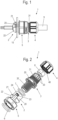
Figur 1- eine Ansicht einer erfindungsgemäßen Halbverschraubung in einer montierten Position;
Figur 2- eine Explosionsdarstellung der Halbverschraubung der
Figur 1 Figur 3- eine perspektivische Ansicht der Halbverschraubung der
Figur 2 Figur 4- eine Schnittansicht der Halbverschraubung der
Figur 3 - Figuren 5A und 5B
- zwei Ansichten des Zwischenstutzens der Halbverschraubung;
- Figuren 6A und 6B
- zwei Ansichten des Spannelementes der Halbverschraubung;
- Figuren 7A und 7B
- zwei Ansichten der Mutter der Halbverschraubung;
Figur 8- eine Ansicht einer Halbverschraubung gemäß einem modifizierten Ausführungsbeispiel, und
Figur 9- eine perspektivische Ansicht der Mutter der Halbverschraubung der
Figur 8
- figure 1
- a view of a half fitting according to the invention in an assembled position;
- figure 2
- an exploded view of the half screw connection
figure 1 ; - figure 3
- a perspective view of the half screw connection
figure 2 ; - figure 4
- a sectional view of the half screw connection
figure 3 ; - Figures 5A and 5B
- two views of the intermediate piece of the half-screw connection;
- Figures 6A and 6B
- two views of the clamping element of the half screw connection;
- Figures 7A and 7B
- two views of the half-bolting nut;
- figure 8
- a view of a half-screw according to a modified embodiment, and
- figure 9
- a perspective view of the nut of the screw half
figure 8 .
Eine Halbverschraubung 1 dient zur Fixierung eines länglichen Gegenstandes 9, wie einem Kabel, einem Rohr oder einer Leitung zur Durchführung an einer Öffnung eines Wandelementes 10, beispielsweise eines Schaltschrankes oder eines anderen Bauteils.A
Die Halbverschraubung 1 umfasst ein Spannelement 2, das mit mehreren über den Umfang verteilten Federstegen 20 durch die Öffnung in dem Wandelement 10 durchgesteckt ist. Die biegbaren Federstege 20 weisen auf der radial äußeren Seite jeweils einen hervorstehenden Vorsprung 21 auf, der in der montierten Position an einer Seite des Wandelementes 10 zur Anlage kommt. Ferner sind die Federstege 20 im Bereich des Vorsprunges 21 mit einer Anlaufschräge 22 versehen, die dafür sorgt, dass die Federstege 20 beim Durchstecken durch die Öffnung radial nach innen gebogen werden können, um hinter der Öffnung dann zu verrasten.The screw half-
Das Spannelement 2 ist an einem Zwischenstutzen 3 fixiert, auf den an einem ersten Gewinde 31 eine Überwurfmutter 4 aufgeschraubt ist. Durch die Überwurfmutter 4 und den Zwischenstutzen 3 ist der längliche Gegenstand 9 durchgeführt und fixiert.The clamping
Wie in
Der Zwischenstutzen 3 umfasst auf der zu dem Spannelement 2 abgewandten Seite das erste Gewinde 31 zur Fixierung der Überwurfmutter 4 und auf der gegenüberliegenden Seite einen hülsenförmigen Abschnitt mit einem zweiten Gewinde 32, das als Außengewinde ausgebildet ist. Zwischen dem ersten Gewinde 31 und dem zweiten Gewinde 32 ist ein Mehrkant 30, insbesondere ein Sechskant, integral ausgebildet, um den Zwischenstutzen 3 relativ zu der Überwurfmutter 4 oder einer weiteren Mutter 5 zu drehen. An dem ersten Gewinde 31 ist in axiale Richtung ein Käfig aus mehreren Stegen 33 ausgebildet, in die ein ringförmiges Dichtelement 8 eingefügt ist. Durch Aufschrauben der Überwurfmutter 4 kann das Dichtelement 8 gegen den länglichen Gegenstand 9 zur Abdichtung gedrückt werden.On the side facing away from the clamping
Die Halbverschraubung 1 umfasst ferner eine Mutter 5, die auf das zweite Gewinde 32 des Zwischenstutzens 3 aufschraubbar ist. Zwischen der Mutter 5 und dem Mehrkant 30 ist eine Dichtung 7 vorgesehen, die beispielsweise als O-Ring ausgebildet ist.The
In den
Auf dem zweiten Gewinde 32 ist ferner die Mutter 5 aufgeschraubt, die in der montierten Position für ein Verspannen des Spannelementes 2 sorgt. Hierfür wird die Mutter 5 so weit in Richtung des Wandelementes 10 verschraubt, bis diese unmittelbar oder über Zwischenschaltung einer Dichtung 6, insbesondere eines O-Ringes, an dem Wandelement 10 anliegt. Dann wird über das Verschrauben der Mutter 5 das Spannelement 2 aus der Öffnung in dem Wandelement 10 herausgezogen, bis die Vorsprünge 21 an dem Wandelement 10 zur Anlage kommen. Durch Drehen der Mutter 5 kann dabei eine Anpassung an unterschiedliche Wanddicken des Wandelementes 10 vorgenommen werden, beispielsweise kann die Halbverschraubung an Wandelementen 10 mit einer Dicke zwischen 1 mm bis 10 mm, insbesondere 2 mm bis 5 mm, fixiert werden.The
In dem Zwischenstutzen 3 ist eine Durchführung 34 für den länglichen Gegenstand 9 ausgebildet, die im Bereich der Überwurfmutter 4 von dem Dichtelement 8 gebildet ist. Die Überwurfmutter 4 weist neben dem Innengewinde 40 einen schräg nach innen gerichteten Klemmabschnitt 41 auf, so dass beim Aufschrauben der Überwurfmutter 4 die Stege 33 mit dem Dichtelement 8 nach innen gegen den länglichen Gegenstand 9 gedrückt werden.A
In den
In den
In den
Zur Montage wird zunächst das Spannelement 2 in die Öffnung an dem Wandelement 10 eingesteckt, bis die Vorsprünge 21 an einer Rückseite des Wandelementes 10 angeordnet sind. Die Federstege 20 werden nun gegen eine Biegung nach innen gesichert, indem der Zwischenstutzen 3 mit dem zweiten Gewinde 32 in das Spannelement 2 eingeschraubt wird. Im nächsten Schritt wird die Mutter 5 so weit auf dem Gewinde 32 verschraubt, bis das Spannelement über die Vorsprünge 21 in Richtung des Wandelementes 10 verspannt wird und die Mutter 5 unmittelbar oder mittelbar, beispielsweise über Dichtungen 6, an dem Wandelement 10 anliegt. Dadurch ist die Halbverschraubung 1 durch Verspannen an dem Wandelement 10 fixiert, wobei die Dicke des Wandelementes 10 variabel gestaltet sein kann, da die Mutter 5 über die Gewindeverbindung axial verstellbar ist. Die Montage kann optional mit vormontierten Kabeln erfolgen, wobei dies auch nachträglich noch in die Halbverschraubung 1 eingesteckt werden kann.For assembly, the clamping
In dem dargestellten Ausführungsbeispiel ist die Mutter 5 separat von dem Spannelement 2 ausgebildet, um die Halbverschraubung 1 an dem Wandelement 10 zu fixieren. Es ist auch möglich, die Mutter 5 integral mit dem Spannelement 2 auszubilden.In the exemplary embodiment shown, the
In
In
- 11
- Halbverschraubunghalf screw connection
- 22
- Spannelementclamping element
- 33
- Zwischenstutzenintermediate connection
- 44
- Überwurfmutterunion nut
- 5, 5'5, 5'
- MutterMother
- 66
- Dichtungpoetry
- 77
- Dichtungpoetry
- 88th
- Dichtelementsealing element
- 99
- länglicher Gegenstandelongated object
- 1010
- Wandelementwall element
- 2020
- Federstegspring bar
- 2121
- Vorsprunghead Start
- 2222
- Anlaufschrägeleading edge
- 2323
- Aussparungrecess
- 2424
- Innengewindeinner thread
- 3030
- Mehrkantpolygon
- 3131
- Gewindethread
- 3232
- Gewindethread
- 3333
- Stegweb
- 3434
- Durchführungexecution
- 4040
- Innengewindeinner thread
- 4141
- Klemmabschnittclamping section
- 5050
- Innengewindeinner thread
- 5151
- Mehrkantpolygon
- 5252
- Vorsprunghead Start
- 5353
- Verzahnunggearing
Claims (14)
Applications Claiming Priority (1)
| Application Number | Priority Date | Filing Date | Title |
|---|---|---|---|
| DE102022104790.3A DE102022104790A1 (en) | 2022-03-01 | 2022-03-01 | Half-bolting and method of assembling a half-bolting |
Publications (1)
| Publication Number | Publication Date |
|---|---|
| EP4239233A1 true EP4239233A1 (en) | 2023-09-06 |
Family
ID=85076133
Family Applications (1)
| Application Number | Title | Priority Date | Filing Date |
|---|---|---|---|
| EP23153326.6A Pending EP4239233A1 (en) | 2022-03-01 | 2023-01-25 | Half screw and method for assembling a half screw |
Country Status (2)
| Country | Link |
|---|---|
| EP (1) | EP4239233A1 (en) |
| DE (1) | DE102022104790A1 (en) |
Citations (6)
| Publication number | Priority date | Publication date | Assignee | Title |
|---|---|---|---|---|
| US2537183A (en) * | 1949-03-14 | 1951-01-09 | Bloomer Edward James | Coupling connection |
| GB1269499A (en) * | 1968-05-07 | 1972-04-06 | Plastiers Ltd | Pipe connections |
| US20020006309A1 (en) * | 2000-07-12 | 2002-01-17 | Anton Hummel Verwaltungs Gmbh | Connection fitting with clamping collet for elongated bodies |
| EP1710886A1 (en) * | 2005-04-08 | 2006-10-11 | Lapp Engineering & Co | Cable feedthrough |
| EP2225811B1 (en) | 2007-12-20 | 2011-05-18 | Hummel Ag | Connection fitting |
| DE102021106864A1 (en) | 2021-03-19 | 2022-09-22 | CENA-Kunststoff GmbH | half screw connection |
-
2022
- 2022-03-01 DE DE102022104790.3A patent/DE102022104790A1/en active Pending
-
2023
- 2023-01-25 EP EP23153326.6A patent/EP4239233A1/en active Pending
Patent Citations (6)
| Publication number | Priority date | Publication date | Assignee | Title |
|---|---|---|---|---|
| US2537183A (en) * | 1949-03-14 | 1951-01-09 | Bloomer Edward James | Coupling connection |
| GB1269499A (en) * | 1968-05-07 | 1972-04-06 | Plastiers Ltd | Pipe connections |
| US20020006309A1 (en) * | 2000-07-12 | 2002-01-17 | Anton Hummel Verwaltungs Gmbh | Connection fitting with clamping collet for elongated bodies |
| EP1710886A1 (en) * | 2005-04-08 | 2006-10-11 | Lapp Engineering & Co | Cable feedthrough |
| EP2225811B1 (en) | 2007-12-20 | 2011-05-18 | Hummel Ag | Connection fitting |
| DE102021106864A1 (en) | 2021-03-19 | 2022-09-22 | CENA-Kunststoff GmbH | half screw connection |
Also Published As
| Publication number | Publication date |
|---|---|
| DE102022104790A1 (en) | 2023-09-07 |
Similar Documents
| Publication | Publication Date | Title |
|---|---|---|
| DE102011010655B3 (en) | clamp | |
| EP3698056B1 (en) | Tolerance compensation assembly | |
| EP2225811B1 (en) | Connection fitting | |
| EP1201941A2 (en) | Rail connecting device | |
| EP2481939B1 (en) | clamping collar | |
| EP1541878B1 (en) | Fastening system | |
| DE102011005598A1 (en) | Fastening device for mounting on a mounting rail | |
| DE102012221228A1 (en) | Device for compensating tolerances between two screwed components, has spacer ring that acts in axial direction and is moved to component against restoring force of fastener fixedly connected to base element | |
| EP4060838A1 (en) | Cable gland | |
| EP2218924A2 (en) | Fastening device for assembly to a fitting rail | |
| AT410012B (en) | RETENTION DEVICE FOR A CONNECTING ELEMENT | |
| EP2261519A2 (en) | Screw for attaching one component to a second component | |
| DE19631656A1 (en) | Clamp | |
| EP0908637A2 (en) | Nut and pipe clamp | |
| WO2020200776A1 (en) | Multipart adjustment element for a tolerance compensation assembly | |
| DE10315690B4 (en) | Fastening device for a hitch on a longitudinal member of a motor vehicle | |
| EP2456030B1 (en) | One-sided cable bolting | |
| DE3115040A1 (en) | "CONTINUOUSLY ADDIBLE DOWEL" | |
| EP3581811A1 (en) | System for attaching a first component to a second component | |
| DE10200376A1 (en) | Plug-in fastening for end of cable has hollow cylinder with detents fitting into cup with spring and clip, mounted on central spigot | |
| EP4239233A1 (en) | Half screw and method for assembling a half screw | |
| EP3064785A1 (en) | Device for fixing on a component | |
| DE19730269C2 (en) | Device for fastening a first part to a second part | |
| DE102004032053B4 (en) | Pipe clamp with integrated snap lock | |
| EP3626898B1 (en) | Profile pipe system |
Legal Events
| Date | Code | Title | Description |
|---|---|---|---|
| PUAI | Public reference made under article 153(3) epc to a published international application that has entered the european phase |
Free format text: ORIGINAL CODE: 0009012 |
|
| STAA | Information on the status of an ep patent application or granted ep patent |
Free format text: STATUS: THE APPLICATION HAS BEEN PUBLISHED |
|
| AK | Designated contracting states |
Kind code of ref document: A1 Designated state(s): AL AT BE BG CH CY CZ DE DK EE ES FI FR GB GR HR HU IE IS IT LI LT LU LV MC ME MK MT NL NO PL PT RO RS SE SI SK SM TR |
|
| STAA | Information on the status of an ep patent application or granted ep patent |
Free format text: STATUS: REQUEST FOR EXAMINATION WAS MADE |
|
| 17P | Request for examination filed |
Effective date: 20230905 |
|
| RBV | Designated contracting states (corrected) |
Designated state(s): AL AT BE BG CH CY CZ DE DK EE ES FI FR GB GR HR HU IE IS IT LI LT LU LV MC ME MK MT NL NO PL PT RO RS SE SI SK SM TR |