EP4239232B1 - Elektronisches expansionsventil und überwachungsverfahren für ein elektronisches expansionsventil - Google Patents
Elektronisches expansionsventil und überwachungsverfahren für ein elektronisches expansionsventil Download PDFInfo
- Publication number
- EP4239232B1 EP4239232B1 EP21890977.8A EP21890977A EP4239232B1 EP 4239232 B1 EP4239232 B1 EP 4239232B1 EP 21890977 A EP21890977 A EP 21890977A EP 4239232 B1 EP4239232 B1 EP 4239232B1
- Authority
- EP
- European Patent Office
- Prior art keywords
- hall sensors
- induction
- magnetic ring
- drive rotors
- expansion valve
- Prior art date
- Legal status (The legal status is an assumption and is not a legal conclusion. Google has not performed a legal analysis and makes no representation as to the accuracy of the status listed.)
- Active
Links
Images
Classifications
-
- F—MECHANICAL ENGINEERING; LIGHTING; HEATING; WEAPONS; BLASTING
- F16—ENGINEERING ELEMENTS AND UNITS; GENERAL MEASURES FOR PRODUCING AND MAINTAINING EFFECTIVE FUNCTIONING OF MACHINES OR INSTALLATIONS; THERMAL INSULATION IN GENERAL
- F16K—VALVES; TAPS; COCKS; ACTUATING-FLOATS; DEVICES FOR VENTING OR AERATING
- F16K31/00—Actuating devices; Operating means; Releasing devices
- F16K31/02—Actuating devices; Operating means; Releasing devices electric; magnetic
- F16K31/04—Actuating devices; Operating means; Releasing devices electric; magnetic using a motor
-
- F—MECHANICAL ENGINEERING; LIGHTING; HEATING; WEAPONS; BLASTING
- F16—ENGINEERING ELEMENTS AND UNITS; GENERAL MEASURES FOR PRODUCING AND MAINTAINING EFFECTIVE FUNCTIONING OF MACHINES OR INSTALLATIONS; THERMAL INSULATION IN GENERAL
- F16K—VALVES; TAPS; COCKS; ACTUATING-FLOATS; DEVICES FOR VENTING OR AERATING
- F16K1/00—Lift valves or globe valves, i.e. cut-off apparatus with closure members having at least a component of their opening and closing motion perpendicular to the closing faces
-
- F—MECHANICAL ENGINEERING; LIGHTING; HEATING; WEAPONS; BLASTING
- F16—ENGINEERING ELEMENTS AND UNITS; GENERAL MEASURES FOR PRODUCING AND MAINTAINING EFFECTIVE FUNCTIONING OF MACHINES OR INSTALLATIONS; THERMAL INSULATION IN GENERAL
- F16K—VALVES; TAPS; COCKS; ACTUATING-FLOATS; DEVICES FOR VENTING OR AERATING
- F16K37/00—Special means in or on valves or other cut-off apparatus for indicating or recording operation thereof, or for enabling an alarm to be given
- F16K37/0025—Electrical or magnetic means
- F16K37/0033—Electrical or magnetic means using a permanent magnet, e.g. in combination with a reed relays
-
- F—MECHANICAL ENGINEERING; LIGHTING; HEATING; WEAPONS; BLASTING
- F16—ENGINEERING ELEMENTS AND UNITS; GENERAL MEASURES FOR PRODUCING AND MAINTAINING EFFECTIVE FUNCTIONING OF MACHINES OR INSTALLATIONS; THERMAL INSULATION IN GENERAL
- F16K—VALVES; TAPS; COCKS; ACTUATING-FLOATS; DEVICES FOR VENTING OR AERATING
- F16K37/00—Special means in or on valves or other cut-off apparatus for indicating or recording operation thereof, or for enabling an alarm to be given
- F16K37/0025—Electrical or magnetic means
- F16K37/0041—Electrical or magnetic means for measuring valve parameters
-
- F—MECHANICAL ENGINEERING; LIGHTING; HEATING; WEAPONS; BLASTING
- F25—REFRIGERATION OR COOLING; COMBINED HEATING AND REFRIGERATION SYSTEMS; HEAT PUMP SYSTEMS; MANUFACTURE OR STORAGE OF ICE; LIQUEFACTION SOLIDIFICATION OF GASES
- F25B—REFRIGERATION MACHINES, PLANTS OR SYSTEMS; COMBINED HEATING AND REFRIGERATION SYSTEMS; HEAT PUMP SYSTEMS
- F25B41/00—Fluid-circulation arrangements
- F25B41/30—Expansion means; Dispositions thereof
- F25B41/31—Expansion valves
- F25B41/34—Expansion valves with the valve member being actuated by electric means, e.g. by piezoelectric actuators
- F25B41/35—Expansion valves with the valve member being actuated by electric means, e.g. by piezoelectric actuators by rotary motors, e.g. by stepping motors
-
- G—PHYSICS
- G01—MEASURING; TESTING
- G01R—MEASURING ELECTRIC VARIABLES; MEASURING MAGNETIC VARIABLES
- G01R33/00—Arrangements or instruments for measuring magnetic variables
- G01R33/02—Measuring direction or magnitude of magnetic fields or magnetic flux
- G01R33/06—Measuring direction or magnitude of magnetic fields or magnetic flux using galvano-magnetic devices
- G01R33/07—Hall effect devices
- G01R33/072—Constructional adaptation of the sensor to specific applications
-
- Y—GENERAL TAGGING OF NEW TECHNOLOGICAL DEVELOPMENTS; GENERAL TAGGING OF CROSS-SECTIONAL TECHNOLOGIES SPANNING OVER SEVERAL SECTIONS OF THE IPC; TECHNICAL SUBJECTS COVERED BY FORMER USPC CROSS-REFERENCE ART COLLECTIONS [XRACs] AND DIGESTS
- Y02—TECHNOLOGIES OR APPLICATIONS FOR MITIGATION OR ADAPTATION AGAINST CLIMATE CHANGE
- Y02B—CLIMATE CHANGE MITIGATION TECHNOLOGIES RELATED TO BUILDINGS, e.g. HOUSING, HOUSE APPLIANCES OR RELATED END-USER APPLICATIONS
- Y02B30/00—Energy efficient heating, ventilation or air conditioning [HVAC]
- Y02B30/70—Efficient control or regulation technologies, e.g. for control of refrigerant flow, motor or heating
Definitions
- the present invention relates to the technical field of flow control apparatuses, and in particular to an electronic expansion valve and a monitoring method for an electronic expansion valve.
- an electronic expansion valve includes an electric motor.
- the electric motor is controlled by a controller to rotate, and drives a rotor to rotate, and rotation of the electric motor is blocked when the electric motor encounters an obstacle during rotation.
- the electronic expansion valve will abnormally work if the controller cannot accurately detect rotation blocking and take corresponding measures; or the electronic expansion valve will also abnormally work if the controller wrongly reports rotation blocking information of the electric motor.
- the rotor of the electronic expansion valve has two rotation directions, is in a rising phase when rotating towards a first direction, and is in a falling phase when rotating towards a second direction. A rotation condition of the rotor cannot be determined by the controller.
- EP 3 690 294 A1 provides a configuration of an electronic expansion valve in which the Hall sensor is arranged at the periphery close to the rotor. When the rotor rotates, the N poles and S poles of the rotor alternately pass by the Hall sensor which generates a periodic feedback signal from which the controller assesses the operating state of the electronic expansion valve including normal operation and rotor blocking.
- the main objective of the present invention is to provide an electronic expansion valve which is defined in claim 1 and a monitoring method for an electronic expansion valve which is defined in claim 10, so as to solve the problem that a rotation condition of a rotor is able to not be determined in an electronic expansion valve in the related art.
- an electronic expansion valve includes: a frame body, the frame body being provided with an accommodating cavity and a mounting cavity; an induction magnetic ring, the induction magnetic ring being movably arranged in the accommodating cavity in a height direction of the accommodating cavity, and the mounting cavity being at least located on a circumferential outer side of an active area of the accommodating cavity in which the induction magnetic ring is located; and a Hall sensor, there are multiple Hall sensors, at least two Hall sensors of the multiple Hall sensors being located in the mounting cavity and being arranged around a circumferential side of the accommodating cavity, the at least two Hall sensors of the multiple Hall sensors being located at the same height, and the induction magnetic ring being always in a detection range of the multiple Hall sensors.
- distances between the at least two Hall sensors of the multiple Hall sensors and the induction magnetic ring are the same.
- the induction magnetic ring has a rising position and a falling position
- a circumferential side wall of the induction magnetic ring includes an induction surface section, a distance between the induction surface section and an inner side wall of the accommodating cavity being unchanged in an height direction of the accommodating cavity, a projection of a top side of the induction surface section to the multiple Hall sensors being located in the induction portions of the multiple Hall sensors when the induction magnetic ring is located in the falling position, and a projection of a bottom side of the induction surface section to the multiple Hall sensors being located in the induction portions of the multiple Hall sensors when the induction magnetic ring is located in the rising position.
- the circumferential side wall of the induction magnetic ring further includes an upper protective surface section located above the induction surface section and a lower protective surface section located below the induction surface section, the upper protective surface section being in arc transition with a top surface of the induction magnetic ring, and the lower protective surface section being in arc transition with a bottom surface of the induction magnetic ring.
- a height of the induction surface section is greater than a motion stroke of the induction magnetic ring in the height direction of the accommodating cavity.
- the electronic expansion valve further includes drive rotors, where the drive rotors are arranged in the accommodating cavity, the induction magnetic ring is arranged on one side of the drive rotors close to the mounting cavity, the drive rotors drive the induction magnetic ring to rotate, and the drive rotors have a number the same as that of the magnetic poles of the induction magnetic ring.
- the multiple Hall sensors are attached to an outer side wall of the accommodating cavity.
- the electronic expansion valve further includes multiple fixing frames, where the multiple Hall sensors are attached to the outer side wall of the accommodating cavity by means of the multiple fixing frames, and at least two fixing frames of the multiple fixing frames are attached to the at least two Hall sensors of the multiple Hall sensors in a one-to-one corresponding manner, so as to limit the multiple Hall sensors between the outer side wall of the accommodating cavity and the multiple fixing frames.
- a monitoring method for an electronic expansion valve has drive rotors driving an induction magnetic ring of the electronic expansion valve to rotate and multiple Hall sensors for monitoring the induction magnetic ring, and at least two Hall sensors of the multiple Hall sensors are spaced around a circumferential side of the induction magnetic ring; and the monitoring method for an electronic expansion valve includes: simultaneously collecting, by the multiple Hall sensors, a motion condition of the induction magnetic ring respectively, so as to form moving magnetic field curves; comparing the moving magnetic field curves collected by different Hall sensors of the multiple Hall sensors; and determining motion conditions of the drive rotors according to phase differences and/or periods of the different moving magnetic field curves.
- the motion conditions of the drive rotors when the motion conditions of the drive rotors are determined according to the phase differences and/pr periods of the different moving magnetic field curves, the motion conditions of the drive rotors at least include whether the drive rotors rotate, the drive rotors being in a rising phase and the drive rotors being in a falling phase.
- the drive rotors when the motion conditions of the drive rotors are determined according to the phase differences and the periods of the different moving magnetic field curves, the drive rotors being in the rising phase or the falling phase is determined according to the phase differences of the different moving magnetic field curves; and whether the drive rotors rotate is determined according to the periods of the different moving magnetic field curves.
- the electronic expansion valve is provided with an accommodating cavity and a mounting cavity
- the induction magnetic ring is movably arranged in the accommodating cavity in a height direction of the accommodating cavity
- the mounting cavity is at least located on a circumferential outer side of an active area of the accommodating cavity in which the induction magnetic ring is located
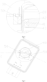
- the at least two Hall sensors are located in the mounting cavity and being arranged around a circumferential side of the accommodating cavity, and an included angle X between projections of centers of induction portions of two adjacent Hall sensors of the multiple Hall sensors and a center of the induction magnetic ring in the height direction of the accommodating cavity and a number n of magnetic poles of the induction magnetic ring satisfy:
- X N * 360 / n + 360 / 2 / n a unit of the included angle X being a degree; and N being an integer.
- distances between the at least two Hall sensors of the multiple Hall sensors and the induction magnetic ring are the same.
- the electronic expansion valve includes the frame body, the induction magnetic ring and the multiple Hall sensors, where the frame body is provided with the accommodating cavity and the mounting cavity; the induction magnetic ring is movably arranged in the accommodating cavity in the height direction of the accommodating cavity, and the mounting cavity is at least located in the circumferential outer side of the active area of the accommodating cavity in which the induction magnetic ring is located; and the at least two Hall sensors are arranged, are located in the mounting cavity, are arranged around the circumferential side of the accommodating cavity, and are located at the same height, and the induction magnetic ring is always located in the detection range of the multiple Hall sensors.
- the accommodating cavity is provided, such that the induction magnetic ring is able to move in the height direction of the accommodating cavity, and moreover, the induction magnetic ring is able to further rotate in the accommodating cavity, and arrangement of the accommodating cavity is able to reduce interference of other structural members on motion of the induction magnetic ring, such that the induction magnetic ring is able to work stably.
- each Hall sensor is able to collect a magnetic field of the induction magnetic ring during motion and form the moving magnetic field curve.
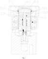
- the above-mentioned figures include the following reference numerals: 10, frame body; 20, accommodating cavity; 30, mounting cavity; 40, induction magnetic ring; 41, induction surface section; 42, upper protective surface section; 43, lower protective surface section; 50, Hall sensor; and 60, drive rotor.
- orientation words such as “upper, lower, top and bottom”, used are usually used for directions shown in the figures, or used for an upright, vertical or gravity direction of a component itself; and similarly, for the convenience of understanding and description, “inside and outside” refers to the inside and outside relative to contours of the components themselves, but the above orientation words are not used to limit the present invention.
- the present invention provides an electronic expansion valve and a monitoring method for an electronic expansion valve.
- an electronic expansion valve includes a frame body 10, an induction magnetic ring 40 and a Hall sensor 50, where the frame body 10 is provided with an accommodating cavity 20 and a mounting cavity 30; the induction magnetic ring 40 is movably arranged in the accommodating cavity 20 in a height direction of the accommodating cavity 20, and the mounting cavity 30 is at least located on a circumferential outer side of an active area of the accommodating cavity 20 in which the induction magnetic ring 40 is located; and there are multiple t Hall sensors 50, the at least two Hall sensors 50 of the multiple Hall sensors 50 are located in the mounting cavity 30 and are arranged around a circumferential side of the accommodating cavity 20, the at least two Hall sensors 50 are located at the same height, and the induction magnetic ring 40 is always in a detection range of the multiple Hall sensors 50.
- the accommodating cavity 20 is provided, such that the induction magnetic ring 40 is able to move in the height direction of the accommodating cavity 20, and moreover, the induction magnetic ring 40 is able to further rotate in the accommodating cavity 20, and arrangement of the accommodating cavity 20 is able to reduce interference of other structural members on motion of the induction magnetic ring 40, such that the induction magnetic ring 40 is able to work stably.
- each Hall sensor 50 is able to collect a magnetic field of the induction magnetic ring 40 during motion and form a moving magnetic field curve.
- the electronic expansion valve further includes drive rotors 60, where the drive rotors 60 are arranged in the accommodating cavity 20, the induction magnetic ring 40 is arranged on one side of the drive rotors 60 close to the mounting cavity 30, the drive rotors 60 drive the induction magnetic ring 40 to rotate, and the drive rotors 60 have a number the same as that of the magnetic poles of the induction magnetic ring 40.
- the drive rotors 60 drive the induction magnetic ring 40 to rotate, and the number of magnetic poles of the drive rotors 60 is the same as that of the magnetic poles of the induction magnetic ring 40, such that the influence of the magnetic poles of the drive rotors 60 on the magnetic field generated by the induction magnetic ring 40 may be avoided, so as to ensure that the multiple Hall sensors 50 may stably work.
- the induction magnetic ring 40 and the drive rotors 60 are able to be integrated, such that synchronous rotation of the drive rotors 60 and the induction magnetic ring 40 is facilitated.
- the drive rotors 60 drive the induction magnetic ring 40 to rotate
- the drive rotors 60 are connected to the induction magnetic ring 40 together, and the induction magnetic ring 40 is able to be synchronously driven to move when the drive rotors 60 rotate.
- the drive rotors 60 rotate, such that the induction magnetic ring 40 rotates;
- the drive rotors 60 are in a rising phase, such that the induction magnet ring 40 is in a rising phase;
- the drive rotors 60 are in a falling phase, such that the induction magnetic ring 40 is in a falling phase. That is, motion of the induction magnetic ring 40 is able to indicate motion of the drive rotors 60.
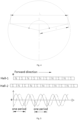
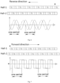
- the motion conditions of the drive rotors 60 also are determined, whether the drive rotors 60 are in the rising phase or the falling phase is further determined, and whether the drive rotors 60 rotate is further determined. It should be noted that since rotation directions of the drive rotors are different when the drive rotors 60 are in the rising phase and in the falling phase, a phase difference of the two moving magnetic field curves is opposite. When the electronic expansion valve is designed, it is necessary to give whether the drive rotors are the rising phase or the falling phase when which curve precedes. Or, it is necessary to give that the positive or negative phase difference of the two moving magnetic field curves corresponds to the rising phase or the falling phase, so as to determine whether the drive rotors 60 are in the rising phase or the falling phase.
- one Hall sensor 50 is marked as a first Hall sensor
- the other Hall sensor 50 is marked as a second Hall sensor
- a phase difference is the moving magnetic field curve of the first Hall sensor minus the moving magnetic field curve of the second Hall sensor.
- the drive rotors 60 being in the rising phase is determined when the phase difference of the two moving magnetic field profiles is positive
- the drive rotors 60 being in the falling phase is determined when the phase difference of the two moving magnetic field curves is negative.
- whether the drive rotors 60 are in the rising phase or the falling phase may be determined according to the positive or negative phase difference of the two moving magnetic field curves.
- the moving magnetic field curve of the induction magnetic ring 40 collected by the multiple Hall sensors 50 is regular, a period of the moving magnetic field curve of the induction magnetic ring 40 is changed when the drive rotors 60 no longer rotate or no longer rotate uniformly, and whether rotation of the electronic expansion valve is blocked is determined by observing the period of the moving magnetic field curve.
- the electronic expansion valve is designed, the period of the moving magnetic field curve of the induction magnetic ring 40 during normal motion is collected in advance. During working of the electronic expansion valve, if the period of the moving magnetic field curve is less than a period of the moving magnetic field curve of the induction magnetic ring 40 during normal motion, rotation of the electronic expansion valve is blocked.
- the included angle between the two adjacent Hall sensors 50 is determined according to the number n of magnetic poles of the induction magnetic ring, and moreover, how many Hall sensors 50 are placed may be also computed. Such an arrangement is able to accurately determine the motion condition of the induction magnetic ring by means of the moving magnetic field curve.
- an angle is generally an acute, and therefore a degree of the included angle X is greater than 0 degree and less than or equal to 180 degrees. Thus, computation of how many Hall sensors 50 are placed is facilitated.
- a relation between the included angle X and the number n of the magnetic poles is a check function.
- distances between the at least two Hall sensors 50 and the induction magnetic ring 40 are the same.
- Such an arrangement enables the strength of a magnetic field of the induction magnetic ring 40 collected by each Hall sensor 50 to be the same, and peaks and periods of the at least two moving magnetic field curves are the same, such that determination of the motion conditions of the drive rotors 60 is facilitated by means of the at least two moving magnetic field curves.
- a unit of the distance L is a centimeter, and a unit of the projection distance r is a centimeter.
- the distance L and the projection distance r are length units.
- the units of the distance L and the projection distance r also are length units of millimeters, meters, etc.
- the distance L between the centers of the induction portions of the two adjacent Hall sensors 50 is related to the number n of the magnetic poles of the induction magnetic ring 40 and the projection distance r from the centers of the multiple Hall sensors 50 to the center of the induction magnetic ring 40 in the height direction of the accommodating cavity 20, and the distance L between the centers of the induction portions of the designed two adjacent Hall sensors 50 is different in the different number n of the magnetic poles of the induction magnetic ring 40.
- the induction magnetic ring 40 has a rising position and a falling position
- a circumferential side wall of the induction magnetic ring 40 includes an induction surface section 41, a distance between the induction surface section 41 and an inner side wall of the accommodating cavity 20 being unchanged in the height direction of the accommodating cavity 20, a projection of a top side of the induction surface section 41 to the multiple Hall sensors 50 being located in the induction portions of the multiple Hall sensors 50 when the induction magnetic ring 40 is located in the falling position, and a projection of a bottom side of the induction surface section 41 to the multiple Hall sensors 50 being located in the induction portions of the multiple Hall sensors 50 when the induction magnetic ring 40 is located in the rising position.
- the magnetic poles of the induction magnetic ring 40 are arranged on the induction surface section 41, and the distance between the induction surface section 41 and an inner side wall of the accommodating cavity 20 is unchanged in the height direction of the accommodating cavity 20, such that the multiple Hall sensors 50 collect the periodically stable magnetic field for determining the motion conditions of the drive rotors 60 by means of the moving magnetic field curves.
- Such an arrangement enables the multiple Hall sensors 50 to always detect the induction surface section 41, so as to ensure that the multiple Hall sensors 50 is able to monitor the motion condition of the induction magnetic ring 40 in real time.
- the circumferential side wall of the induction magnetic ring 40 further includes an upper protective surface section 42 located above the induction surface section 41 and a lower protective surface section 43 located below the induction surface section 41, the upper protective surface section 42 being in arc transition with a top surface of the induction magnetic ring 40, and the lower protective surface section 43 being in arc transition with a bottom surface of the induction magnetic ring 40.
- Arrangement of the upper protective surface section 42 and the lower protective surface section 43 is able to protect the induction surface section 41, so as to avoid collision of the induction surface section 41 by other structures, thereby ensuring working stability of the induction surface section 41, so as to produce a stable magnetic field.
- the upper protective surface section 42 is in arc transition with the top surface of the induction magnetic ring 40
- the lower protective surface section 43 is in arc transition with the bottom surface of the induction magnetic ring 40, and such an arrangement facilitates motion of the induction magnetic ring 40 in the accommodating cavity 20, such that scratching of the induction magnetic ring 40 against the inner side wall of the accommodating cavity 20 is avoided, and working stability of the induction magnetic ring 40 is ensured.
- a height of the induction surface section 41 is greater than a motion stroke of the induction magnetic ring 40 in the height direction of the accommodating cavity 20.
- the multiple Hall sensors 50 are attached to an outer side wall of the accommodating cavity 20. Such as arrangement facilitates mounting of the multiple Hall sensors 50, and facilitates the same distance between the multiple Hall sensors 50 and the induction magnetic ring 40, so as to ensure detection stability of the multiple Hall sensors 50.
- the accommodating cavity 20 has a cylindrical shape
- the induction magnetic ring 40 has a circular pie shape.
- the electronic expansion valve further includes multiple fixing frames, where the multiple Hall sensors 50 are attached to the outer side wall of the accommodating cavity 20 by means of the multiple fixing frames, and at least two fixing frames of the multiple fixing frames are attached to the at least two Hall sensors 50 in a one-to-one corresponding manner, so as to limit the multiple Hall sensors 50 between the outer side wall of the accommodating cavity 20 and the multiple fixing frames.
- Arrangement of the multiple fixing frames provides mounting positions for the multiple Hall sensors 50, such that the multiple Hall sensors 50 are attached to the outer side wall of the accommodating cavity 20.
- the multiple fixing frames further protect the multiple Hall sensors 50, so as to avoid collision of other structural members on the multiple Hall sensors 50, thereby ensuring stable work of the multiple Hall sensors 50.
- the electronic expansion valve has drive rotors 60 driving an induction magnetic ring 40 of the electronic expansion valve to rotate and multiple Hall sensors 50 for monitoring the induction magnetic ring 40, and the at least two Hall sensors 50 are spaced around a circumferential side of the induction magnetic ring 40; and a monitoring method for an electronic expansion valve includes: simultaneously collect, by the multiple Hall sensors 50, a motion condition of the induction magnetic ring 40 respectively, so as to form moving magnetic field curves; compare the moving magnetic field curves collected by different Hall sensors; and determine motion conditions of the drive rotors 60 according to phase differences and/or periods of the different moving magnetic field curves.
- each Hall sensor 50 is able to collect the magnetic field of the induction magnetic ring 40 during motion and form a moving magnetic field curve.
- the motion conditions of the drive rotors 60 are determined by analyzing a relation of the at least two moving magnetic field curves. Specifically, when the motion conditions of the drive rotors 60 are determined according to the phase differences and/or periods of the different moving magnetic field curves, the motion conditions of the drive rotors 60 at least include whether the drive rotors 60 rotate, the drive rotors 60 being in a rising phase and the drive rotors 60 being in a falling phase.
- the drive rotors 60 when the motion conditions of the drive rotors 60 are determined according to the phase differences and/or the periods of the different moving magnetic field curves, the drive rotors 60 being in the rising phase or the falling phase is determined according to the phase differences of the different moving magnetic field curves; and whether the drive rotors 60 rotate is determined according to the periods of the different moving magnetic field curves.
- the moving magnetic field curve of the induction magnetic ring 40 collected by the multiple Hall sensors 50 is regular, periods of the moving magnetic field curves of the drive rotors 60 are changed when the drive rotors 60 no longer rotate or no longer rotate uniformly, and whether rotation of the induction magnetic ring is blocked is determined by observing the period of the moving magnetic field curve.
- the electronic expansion valve is designed, the period of the moving magnetic field curve of the induction magnetic ring 40 during normal motion is collected in advance. During working of the electronic expansion valve, if the period of the moving magnetic field curve is less than a period of the moving magnetic field curve of the induction magnetic ring 40 during normal motion, rotation of the electronic expansion valve is blocked.
- the two Hall sensors 50 are arranged, when the motion conditions of the drive rotors 60 are determined according to the phase differences and/or the periods of the different moving magnetic field curves, if the phase difference of the two moving magnetic field curves is positive, the drive rotors 60 being in the rising phase is determined; and if the phase difference of the two moving magnetic field curves is negative, the drive rotors 60 being in the falling phase is determined.
- One Hall sensor 50 is marked as a first Hall sensor
- the other Hall sensor 50 is marked as a second Hall sensor
- the phase difference is the moving magnetic field curve of the first Hall sensor minus the moving magnetic field curve of the second Hall sensor.
- the drive rotors 60 being in the rising phase is determined when the phase difference of the two moving magnetic field curves is positive, and the drive rotors 60 being in the falling phase is determined when the phase difference of the two moving magnetic field curves is negative. Therefore, whether the drive rotors 60 are in the rising phase or the falling phase may be determined according to the positive or negative phase difference of the two moving magnetic field curves.
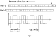
- a solid line is a moving magnetic field curve of a first Hall sensor 50
- a dashed line is a moving magnetic field curve of a second Hall sensor 50.
- moving magnetic field curves of Hall sensors 50 are square waves
- a solid line is the moving magnetic field curve of a first Hall sensor 50
- a dashed line is a moving magnetic field curve of a second Hall sensor 50.
- the at least two Hall sensors 50 are arranged, the phase difference of the moving magnetic field curves of the two Hall sensors 50 are only referred, and the phase difference of the moving magnetic field curves of the at least two Hall sensors 50 are also referred.
- the included angle between the two adjacent Hall sensors 50 is determined according to the number n of magnetic poles of the induction magnetic ring, and moreover, how many Hall sensors 50 are placed may be also computed. Such an arrangement is accurately determine the motion condition of the induction magnetic ring by means of the moving magnetic field curve.
- distances between the at least two Hall sensors 50 and the induction magnetic ring 40 are the same.
- Such an arrangement enables the strength of a magnetic field of the induction magnetic ring 40 collected by each Hall sensor 50 to be the same, and peaks and periods of the at least two moving magnetic field curves are the same, such that determination of the motion conditions of the drive rotors 60 is facilitated by means of the at least two moving magnetic field curves.
- a unit of the distance L is a centimeter, and a unit of the projection distance r is a centimeter.
- the distance L and the projection distance r are length units.
- the units of the distance L and the projection distance r also are length units of millimeters, meters, etc.
- the distance L between the centers of the induction portions of the two adjacent Hall sensors 50 is related to the number n of the magnetic poles of the induction magnetic ring 40 and the projection distance r from the centers of the multiple Hall sensors 50 to the center of the induction magnetic ring 40 in the height direction of the accommodating cavity 20, and the distance L between the centers of the induction portions of the designed two adjacent Hall sensors 50 is different in the different number n of the magnetic poles of the induction magnetic ring 40.
- the electronic expansion valve further includes a coil assembly, a valve body assembly and a sleeve, where the coil assembly is arranged in the frame body 10 and located on an outer side of the drive rotors 60, the valve body assembly includes a valve seat and a valve needle, the valve needle moving along with the drive rotors 60 to open and close a valve port on the valve seat, the sleeve is arranged in the accommodating cavity 20, is fixedly connected to the valve body assembly, and is provided with a cavity, and the drive rotors 60 move in the sleeve.
Landscapes
- Engineering & Computer Science (AREA)
- General Engineering & Computer Science (AREA)
- Mechanical Engineering (AREA)
- Physics & Mathematics (AREA)
- Thermal Sciences (AREA)
- Condensed Matter Physics & Semiconductors (AREA)
- General Physics & Mathematics (AREA)
- Transmission And Conversion Of Sensor Element Output (AREA)
- Measurement Of Length, Angles, Or The Like Using Electric Or Magnetic Means (AREA)
Claims (15)
- Elektronisches Expansionsventil, umfassend:einen Rahmenkörper (10), wobei der Rahmenkörper (10) mit einem Aufnahmehohlraum (20) und einem Montagehohlraum (30) versehen ist;einen Induktionsmagnetring (40), wobei der Induktionsmagnetring (40) in dem Aufnahmehohlraum (20) in einer Höhenrichtung des Aufnahmehohlraums (20) beweglich angeordnet ist und sich der Montagehohlraum (30) zumindest auf einer Umfangsaußenseite eines aktiven Bereichs des Aufnahmehohlraums (20) befindet, in dem sich der Induktionsmagnetring (40) befindet; undeinen Hallsensor (50), mehrere Hallsensoren (50) vorhanden sind, wobei sich mindestens zwei Hallsensoren (50) der mehreren Hallsensoren (50) in dem Montagehohlraum (30) befinden und um eine Umfangsseite des Aufnahmehohlraums (20) herum angeordnet sind, wobei sich die mindestens zwei Hallsensoren (50) der mehreren Hallsensoren (50) auf gleicher Höhe befinden und sich der Induktionsmagnetring (40) stets in einem Erfassungsbereich der mehreren Hallsensoren (50) befindet.
- Elektronisches Expansionsventil nach Anspruch 1, wobei ein eingeschlossener Winkel X zwischen Projektionen von Mittelpunkten von Induktionsabschnitten von zwei benachbarten Hallsensoren (50) der mehreren Hallsensoren (50) und einem Mittelpunkt des Induktionsmagnetrings (40) in einer Höhenrichtung des Aufnahmehohlraums (20) und einer Anzahl n von Magnetpolen des Induktionsmagnetrings (40) erfüllt:

- Elektronisches Expansionsventil nach Anspruch 1, wobei Abstände zwischen den zumindest zwei Hallsensoren (50) der mehreren Hallsensoren (50) und dem Induktionsmagnetring (40) gleich sind.
- Elektronisches Expansionsventil nach Anspruch 3, wobei ein Abstand L zwischen Mittelpunkten von Induktionsabschnitten von zwei benachbarten Hallsensoren (50) der mehreren Hallsensoren (50), eine Anzahl n von Magnetpolen des Induktionsmagnetrings (40) und ein Projektionsabstand r von den Mittelpunkten der mehreren Hallsensoren (50) zu einem Mittelpunkt des Induktionsmagnetrings (40) in einer Höhenrichtung des Aufnahmehohlraums (20) erfüllen:

- Elektronisches Expansionsventil nach einem der Ansprüche 1-4, wobei der Induktionsmagnetring (40) eine ansteigende Position und eine abfallende Position aufweist und eine Umfangsseitenwand des Induktionsmagnetrings (40) eine Induktionsflächensektion (41) umfasst, wobei ein Abstand zwischen der Induktionsflächensektion (41) und einer inneren Seitenwand des Aufnahmehohlraums (20) in einer Höhenrichtung des Aufnahmehohlraums (20) unverändert ist,wobei sich eine Projektion einer Oberseite der Induktionsflächensektion (41) auf die mehreren Hallsensoren (50) in den Induktionsabschnitten der mehreren Hallsensoren (50) befindet, wenn sich der Induktionsmagnetring (40) in der abfallenden Position befindet, undwobei sich eine Projektion einer Unterseite der Induktionsflächensektion (41) auf die mehreren Hallsensoren (50) in den Induktionsabschnitten der mehreren Hallsensoren (50) befindet, wenn sich der Induktionsmagnetring (40) in der ansteigenden Position befindet.
- Elektronisches Expansionsventil nach Anspruch 5, wobei die Umfangsseitenwand des Induktionsmagnetrings (40) ferner eine oberen Schutzflächensektion (42), die sich über der Induktionsflächensektion (41) befindet, und eine untere Schutzflächensektion (43), die sich unter der Induktionsflächensektion (41) befindet, umfasst, wobei die obere Schutzflächensektion (42) in einem Bogenübergang mit einer oberseitigen Fläche des Induktionsmagnetrings (40) ist und die untere Schutzflächensektion (43) in einem Bogenübergang mit einer unterseitigen Fläche des Induktionsmagnetrings (40) ist.
- Elektronisches Expansionsventil nach Anspruch 5, wobei eine Höhe der Induktionsflächensektion (41) größer ist als ein Bewegungshub des Induktionsmagnetrings (40) in der Höhenrichtung des Aufnahmehohlraums (20).
- Elektronisches Expansionsventil nach einem der Ansprüche 1-4, ferner umfassend Antriebsrotoren (60), wobei die Antriebsrotoren (60) in dem Aufnahmehohlraum (20) angeordnet sind, der Induktionsmagnetring (40) auf einer Seite der Antriebsrotoren (60) in der Nähe des Montagehohlraums (30) angeordnet ist, die Antriebsrotoren (60) den Induktionsmagnetring (40) zur Drehung antreiben und die Antriebsrotoren (60) eine Anzahl aufweisen, die der Anzahl der Magnetpole des Induktionsmagnetrings (40) gleich ist.
- Elektronisches Expansionsventil nach einem der Ansprüche 1-4, wobei die mehreren Hallsensoren (50) an einer äußeren Seitenwand des Aufnahmehohlraums (20) angebracht sind, wobei das elektronische Expansionsventil ferner mehrere Befestigungsrahmen umfasst, wobei die mehreren Hallsensoren (50) mittels der mehreren Befestigungsrahmen an der Außenseitenwand des Aufnahmehohlraums (20) angebracht sind und mindestens zwei Befestigungsrahmen der mehreren Befestigungsrahmen an den mindestens zwei Hallsensoren (50) der mehreren Hallsensoren (50) in einer eins-zueins entsprechenden Weise angebracht sind, um die mehreren Hallsensoren (50) zwischen der Außenseitenwand des Aufnahmehohlraums (20) und den mehreren Befestigungsrahmen zu begrenzen.
- Überwachungsverfahren für ein elektronisches Expansionsventil, wobei das elektronische Expansionsventil Antriebsrotoren (60), die einen Induktionsmagnetring (40) des elektronischen Expansionsventils zum Drehen antreiben, und mehrere Hallsensoren (50) zum Überwachen des Induktionsmagnetrings (40) aufweist und mindestens zwei Hallsensoren (50) der mehreren Hallsensoren (50) um eine Umfangsseite des Induktionsmagnetrings (40) beabstandet sind; und das Überwachungsverfahren für ein elektronisches Expansionsventil umfasst:gleichzeitiges Erheben jeweils einer Bewegungsbedingung des Induktionsmagnetrings (40) durch die mehreren Hallsensoren (50), um Kurven eines sich bewegenden Magnetfeldes;Vergleichen der Kurven des sich bewegenden Magnetfeldes, die von verschiedenen Hallsensoren (50) der mehreren Hallsensoren (50) erhoben werden; undBestimmen von Bewegungsbedingungen der Antriebsrotoren (60) gemäß Phasendifferenzen der verschiedenen Kurven des sich bewegenden Magnetfeldes; oder Bestimmen von Bewegungsbedingungen der Antriebsrotoren (60) gemäß Perioden von Phasendifferenzen der verschiedenen Kurven des sich bewegenden Magnetfeldes; oder Bestimmen von Bewegungsbedingungen der Antriebsrotoren (60) gemäß Phasendifferenzen und Perioden der verschiedenen Kurven des sich bewegenden Magnetfeldes.
- Überwachungsverfahren für ein elektronisches Expansionsventil nach Anspruch 10, wobeiwenn die Bewegungsbedingungen der Antriebsrotoren (60) gemäß den Phasendifferenzen der verschiedenen Kurven des sich bewegenden Magnetfeldes bestimmt werden, die Bewegungsbedingungen der Antriebsrotoren (60) zumindest umfassen, ob sich die Antriebsrotoren (60) drehen, wobei die Antriebsrotoren (60) in einer ansteigenden Phase sind und die Antriebsrotoren (60) in einer abfallenden Phase sind; oderwenn die Bewegungsbedingungen der Antriebsrotoren (60) gemäß den Perioden der Phasendifferenzen der verschiedenen Kurven des sich bewegenden Magnetfeldes bestimmt werden, die Bewegungsbedingungen der Antriebsrotoren (60) zumindest umfassen, ob sich die Antriebsrotoren (60) drehen, wobei die Antriebsrotoren (60) in einer ansteigenden Phase sind und die Antriebsrotoren (60) in einer abfallenden Phase sind; oderwenn die Bewegungsbedingungen der Antriebsrotoren (60) gemäß den Phasendifferenzen und den Perioden der verschiedenen Kurven des sich bewegenden Magnetfeldes bestimmt werden, umfassen die Bewegungsbedingungen der Antriebsrotoren (60) zumindest, ob sich die Antriebsrotoren (60) drehen, wobei die Antriebsrotoren (60) in einer ansteigenden Phase sind und die Antriebsrotoren (60) in einer abfallenden Phase sind.
- Überwachungsverfahren für ein elektronisches Expansionsventil nach Anspruch 11, wobei, wenn die Bewegungsbedingungen der Antriebsrotoren (60) gemäß den Phasendifferenzen und den Perioden der verschiedenen Kurven des sich bewegenden Magnetfeldes bestimmt werden, die Antriebsrotoren (60) in der ansteigenden Phase sind oder in der abfallenden Phase sind, gemäß den Phasendifferenzen der verschiedenen Kurven des sich bewegenden Magnetfeldes bestimmt werden; und ob sich die Antriebsrotoren (60) drehen, gemäß den Perioden der verschiedenen Kurven des sich bewegenden Magnetfeldes bestimmt wird.
- Überwachungsverfahren für ein elektronisches Expansionsventil nach Anspruch 12, wobei das elektronische Expansionsventil mit einem Aufnahmehohlraum (20) und einem Montagehohlraum (30) versehen ist, der Induktionsmagnetring (40) in dem Aufnahmehohlraum (20) in einer Höhenrichtung des Aufnahmehohlraums (20) beweglich angeordnet ist und sich der Montagehohlraum (30) zumindest auf einer Umfangsaußenseite eines aktiven Bereichs des Aufnahmehohlraums (20) befindet, in dem sich der Induktionsmagnetring (40) befindet; und die mindestens zwei Hallsensoren (50) der mehreren Hallsensoren (50) befinden sich im Montagehohlraum (30) und wobei sie um eine Umfangsseite des Aufnahmehohlraums (20) herum angeordnet sind, und ein eingeschlossener Winkel X zwischen Projektionen von Mittelpunkten von Induktionsabschnitten von zwei benachbarten Hallsensoren (50) der mehreren Hallsensoren (50) und einem Mittelpunkt des Induktionsmagnetrings (40) in der Höhenrichtung des Aufnahmehohlraums (20) und einer Anzahl n von Magnetpolen des Induktionsmagnetrings (40) erfüllen:

- Überwachungsverfahren für ein elektronisches Expansionsventil nach Anspruch 13, wobei Abstände zwischen den zumindest zwei Hallsensoren (50) der mehreren Hallsensoren (50) und dem Induktionsmagnetring (40) gleich sind.
- Überwachungsverfahren für ein elektronisches Expansionsventil nach Anspruch 14, wobei ein Abstand L zwischen den Mittelpunkten der Induktionsabschnitte der zwei benachbarten Hallsensoren (50) der mehreren Hallsensoren (50), eine Anzahl n der Magnetpole des Induktionsmagnetrings (40) und ein Projektionsabstand r von den Mittelpunkten der mehreren Hallsensoren (50) zum Mittelpunkt des Induktionsmagnetrings (40) in der Höhenrichtung des Aufnahmehohlraums (20) erfüllen:

Applications Claiming Priority (2)
| Application Number | Priority Date | Filing Date | Title |
|---|---|---|---|
| CN202011248724.XA CN114458806A (zh) | 2020-11-10 | 2020-11-10 | 电子膨胀阀和用于电子膨胀阀的监测方法 |
| PCT/CN2021/127139 WO2022100450A1 (zh) | 2020-11-10 | 2021-10-28 | 电子膨胀阀和用于电子膨胀阀的监测方法 |
Publications (3)
| Publication Number | Publication Date |
|---|---|
| EP4239232A1 EP4239232A1 (de) | 2023-09-06 |
| EP4239232A4 EP4239232A4 (de) | 2024-05-01 |
| EP4239232B1 true EP4239232B1 (de) | 2025-04-30 |
Family
ID=81404085
Family Applications (1)
| Application Number | Title | Priority Date | Filing Date |
|---|---|---|---|
| EP21890977.8A Active EP4239232B1 (de) | 2020-11-10 | 2021-10-28 | Elektronisches expansionsventil und überwachungsverfahren für ein elektronisches expansionsventil |
Country Status (3)
| Country | Link |
|---|---|
| EP (1) | EP4239232B1 (de) |
| CN (1) | CN114458806A (de) |
| WO (1) | WO2022100450A1 (de) |
Families Citing this family (5)
| Publication number | Priority date | Publication date | Assignee | Title |
|---|---|---|---|---|
| CN220185983U (zh) * | 2023-05-15 | 2023-12-15 | 盾安汽车热管理科技有限公司 | 电子膨胀阀 |
| CN119508499A (zh) * | 2023-08-23 | 2025-02-25 | 广东美芝制冷设备有限公司 | 电子膨胀阀、制冷设备和车辆 |
| CN118009067A (zh) * | 2024-03-07 | 2024-05-10 | 林鹏达 | 燃气自闭阀语音报警器 |
| CN119289113A (zh) * | 2024-12-06 | 2025-01-10 | 广汽埃安新能源汽车股份有限公司 | 一种冷媒双控阀及其控制方法 |
| CN120576108A (zh) * | 2025-06-30 | 2025-09-02 | 江苏海澄水务工程有限公司 | 一种具备防沙节能效果的潜水泵机组 |
Family Cites Families (15)
| Publication number | Priority date | Publication date | Assignee | Title |
|---|---|---|---|---|
| JP4335364B2 (ja) * | 1999-06-29 | 2009-09-30 | 株式会社不二工機 | 電動弁の弁開度検出装置および電動弁の弁開度制御装置 |
| JP2003042325A (ja) * | 2001-07-26 | 2003-02-13 | Saginomiya Seisakusho Inc | 電動弁及び電動弁の駆動装置並びに冷凍サイクル装置 |
| CN1728534A (zh) * | 2004-06-11 | 2006-02-01 | 国际整流器公司 | 对无刷直流电机的霍尔传感器的定位 |
| CN202216963U (zh) * | 2011-09-06 | 2012-05-09 | 深圳市科创达微电子有限公司 | 旋转体的前端检测处理装置 |
| CN103234564B (zh) * | 2013-04-15 | 2015-11-11 | 山东联友通信科技发展有限公司 | 基于二维磁编码的定位方法及定位系统 |
| CN106705392B (zh) * | 2017-01-05 | 2022-03-25 | 广东美的制冷设备有限公司 | 空调器及其电机堵转检测装置和门板控制系统 |
| CN106869670B (zh) * | 2017-03-23 | 2019-08-30 | 东莞雅音电子科技有限公司 | 电动车门检测装置及检测控制方法 |
| CN109555891B (zh) * | 2017-09-27 | 2020-08-25 | 杭州三花研究院有限公司 | 电子膨胀阀 |
| CN207248262U (zh) * | 2017-09-30 | 2018-04-17 | 北京妙思特仪表有限公司 | 一种浮子流量计的流量表 |
| CN107701782B (zh) * | 2017-11-20 | 2019-07-19 | 昆山伊斯科特电子科技有限公司 | 一种利用无刷电机的霍尔信号的阀门控制器 |
| CN111365511B (zh) * | 2018-12-26 | 2022-01-11 | 浙江三花智能控制股份有限公司 | 球阀以及控制方法 |
| DE102019206197A1 (de) * | 2019-04-30 | 2020-11-05 | Mahle International Gmbh | Expansionsventil |
| CN210240731U (zh) * | 2019-07-15 | 2020-04-03 | 杭州三花研究院有限公司 | 控制装置及电动阀 |
| CN213809122U (zh) * | 2020-11-10 | 2021-07-27 | 盾安汽车热管理科技有限公司 | 电子膨胀阀 |
| CN213809121U (zh) * | 2020-11-10 | 2021-07-27 | 盾安汽车热管理科技有限公司 | 电子膨胀阀 |
-
2020
- 2020-11-10 CN CN202011248724.XA patent/CN114458806A/zh active Pending
-
2021
- 2021-10-28 WO PCT/CN2021/127139 patent/WO2022100450A1/zh not_active Ceased
- 2021-10-28 EP EP21890977.8A patent/EP4239232B1/de active Active
Also Published As
| Publication number | Publication date |
|---|---|
| WO2022100450A1 (zh) | 2022-05-19 |
| EP4239232A1 (de) | 2023-09-06 |
| CN114458806A (zh) | 2022-05-10 |
| EP4239232A4 (de) | 2024-05-01 |
Similar Documents
| Publication | Publication Date | Title |
|---|---|---|
| EP4239232B1 (de) | Elektronisches expansionsventil und überwachungsverfahren für ein elektronisches expansionsventil | |
| JP6014260B2 (ja) | 建設機械の制御システム、及び建設機械の制御方法 | |
| US7117609B2 (en) | Device, CNC measuring device, and method for measuring a rotationally symmetric precision part | |
| EP2837915B1 (de) | Resolvervorrichtung, motorsteuerungsvorrichtung und motorsteuerungsverfahren | |
| CN108427410B (zh) | 自移动设备 | |
| JPH10332832A (ja) | ガンマ線カメラ | |
| US11753275B2 (en) | Method for preventive maintenance of an elevator and an elevator system | |
| CN105388317A (zh) | 用于监控旋转构件的速度和位置的方法和设备 | |
| CN214686431U (zh) | 一种固定角度的重载转台高精度控制系统 | |
| CN213809121U (zh) | 电子膨胀阀 | |
| EP2800269A1 (de) | Permanentmagnetmotorsteuerung | |
| EP4246027A1 (de) | Elektronisches expansionsventil und überwachungsverfahren dafür | |
| JPH11160009A (ja) | ストロークセンシングシリンダの絶対位置検出方法 | |
| CN102743180B (zh) | C形臂x射线机的防碰撞方法、装置以及c形臂x射线机 | |
| ES2851323T3 (es) | Procedimiento para detectar una pérdida de paso en un motor paso a paso y control electrónico asociado de un motor paso a paso | |
| CN213809122U (zh) | 电子膨胀阀 | |
| EP4692617A1 (de) | Elektronisches expansionsventil | |
| CN211042090U (zh) | 一种转轴定位装置 | |
| EP3885077A1 (de) | Robotersensoranordnungssystem | |
| EP3078939A1 (de) | Verfahren zur steuerung eines schrittmotors | |
| EP2632653B1 (de) | Verfahren und vorrichtung zur überwachung und begrenzung der geschwindigkeit eines industrieroboters | |
| JPS63290182A (ja) | トルク制御式回転電動機械 | |
| KR101462832B1 (ko) | 영구자석을 이용한 가감속 장치 및 이를 포함하는 전동기 장치 | |
| CN209764108U (zh) | 一种建筑物工程检测设备 | |
| JP3675616B2 (ja) | パワーウインド装置の挟み込み検知方法 |
Legal Events
| Date | Code | Title | Description |
|---|---|---|---|
| STAA | Information on the status of an ep patent application or granted ep patent |
Free format text: STATUS: THE INTERNATIONAL PUBLICATION HAS BEEN MADE |
|
| PUAI | Public reference made under article 153(3) epc to a published international application that has entered the european phase |
Free format text: ORIGINAL CODE: 0009012 |
|
| STAA | Information on the status of an ep patent application or granted ep patent |
Free format text: STATUS: REQUEST FOR EXAMINATION WAS MADE |
|
| 17P | Request for examination filed |
Effective date: 20230530 |
|
| AK | Designated contracting states |
Kind code of ref document: A1 Designated state(s): AL AT BE BG CH CY CZ DE DK EE ES FI FR GB GR HR HU IE IS IT LI LT LU LV MC MK MT NL NO PL PT RO RS SE SI SK SM TR |
|
| DAV | Request for validation of the european patent (deleted) | ||
| DAX | Request for extension of the european patent (deleted) | ||
| A4 | Supplementary search report drawn up and despatched |
Effective date: 20240404 |
|
| RIC1 | Information provided on ipc code assigned before grant |
Ipc: G01R 33/00 20060101ALI20240327BHEP Ipc: F16K 37/00 20060101ALI20240327BHEP Ipc: F16K 31/04 20060101AFI20240327BHEP |
|
| GRAP | Despatch of communication of intention to grant a patent |
Free format text: ORIGINAL CODE: EPIDOSNIGR1 |
|
| STAA | Information on the status of an ep patent application or granted ep patent |
Free format text: STATUS: GRANT OF PATENT IS INTENDED |
|
| RIC1 | Information provided on ipc code assigned before grant |
Ipc: G01R 33/00 20060101ALI20241119BHEP Ipc: F16K 37/00 20060101ALI20241119BHEP Ipc: F16K 31/04 20060101AFI20241119BHEP |
|
| INTG | Intention to grant announced |
Effective date: 20241213 |
|
| GRAS | Grant fee paid |
Free format text: ORIGINAL CODE: EPIDOSNIGR3 |
|
| GRAA | (expected) grant |
Free format text: ORIGINAL CODE: 0009210 |
|
| STAA | Information on the status of an ep patent application or granted ep patent |
Free format text: STATUS: THE PATENT HAS BEEN GRANTED |
|
| AK | Designated contracting states |
Kind code of ref document: B1 Designated state(s): AL AT BE BG CH CY CZ DE DK EE ES FI FR GB GR HR HU IE IS IT LI LT LU LV MC MK MT NL NO PL PT RO RS SE SI SK SM TR |
|
| REG | Reference to a national code |
Ref country code: CH Ref legal event code: EP Ref country code: GB Ref legal event code: FG4D |
|
| REG | Reference to a national code |
Ref country code: IE Ref legal event code: FG4D |
|
| REG | Reference to a national code |
Ref country code: DE Ref legal event code: R096 Ref document number: 602021030171 Country of ref document: DE |
|
| P01 | Opt-out of the competence of the unified patent court (upc) registered |
Free format text: CASE NUMBER: APP_19123/2025 Effective date: 20250422 |
|
| REG | Reference to a national code |
Ref country code: NL Ref legal event code: MP Effective date: 20250430 |
|
| REG | Reference to a national code |
Ref country code: AT Ref legal event code: MK05 Ref document number: 1790280 Country of ref document: AT Kind code of ref document: T Effective date: 20250430 |
|
| PG25 | Lapsed in a contracting state [announced via postgrant information from national office to epo] |
Ref country code: PT Free format text: LAPSE BECAUSE OF FAILURE TO SUBMIT A TRANSLATION OF THE DESCRIPTION OR TO PAY THE FEE WITHIN THE PRESCRIBED TIME-LIMIT Effective date: 20250901 Ref country code: FI Free format text: LAPSE BECAUSE OF FAILURE TO SUBMIT A TRANSLATION OF THE DESCRIPTION OR TO PAY THE FEE WITHIN THE PRESCRIBED TIME-LIMIT Effective date: 20250430 Ref country code: ES Free format text: LAPSE BECAUSE OF FAILURE TO SUBMIT A TRANSLATION OF THE DESCRIPTION OR TO PAY THE FEE WITHIN THE PRESCRIBED TIME-LIMIT Effective date: 20250430 |
|
| REG | Reference to a national code |
Ref country code: LT Ref legal event code: MG9D |
|
| PG25 | Lapsed in a contracting state [announced via postgrant information from national office to epo] |
Ref country code: GR Free format text: LAPSE BECAUSE OF FAILURE TO SUBMIT A TRANSLATION OF THE DESCRIPTION OR TO PAY THE FEE WITHIN THE PRESCRIBED TIME-LIMIT Effective date: 20250731 Ref country code: NO Free format text: LAPSE BECAUSE OF FAILURE TO SUBMIT A TRANSLATION OF THE DESCRIPTION OR TO PAY THE FEE WITHIN THE PRESCRIBED TIME-LIMIT Effective date: 20250730 |
|
| PG25 | Lapsed in a contracting state [announced via postgrant information from national office to epo] |
Ref country code: NL Free format text: LAPSE BECAUSE OF FAILURE TO SUBMIT A TRANSLATION OF THE DESCRIPTION OR TO PAY THE FEE WITHIN THE PRESCRIBED TIME-LIMIT Effective date: 20250430 Ref country code: PL Free format text: LAPSE BECAUSE OF FAILURE TO SUBMIT A TRANSLATION OF THE DESCRIPTION OR TO PAY THE FEE WITHIN THE PRESCRIBED TIME-LIMIT Effective date: 20250430 |
|
| PG25 | Lapsed in a contracting state [announced via postgrant information from national office to epo] |
Ref country code: BG Free format text: LAPSE BECAUSE OF FAILURE TO SUBMIT A TRANSLATION OF THE DESCRIPTION OR TO PAY THE FEE WITHIN THE PRESCRIBED TIME-LIMIT Effective date: 20250430 |
|
| PG25 | Lapsed in a contracting state [announced via postgrant information from national office to epo] |
Ref country code: HR Free format text: LAPSE BECAUSE OF FAILURE TO SUBMIT A TRANSLATION OF THE DESCRIPTION OR TO PAY THE FEE WITHIN THE PRESCRIBED TIME-LIMIT Effective date: 20250430 |
|
| PG25 | Lapsed in a contracting state [announced via postgrant information from national office to epo] |
Ref country code: AT Free format text: LAPSE BECAUSE OF FAILURE TO SUBMIT A TRANSLATION OF THE DESCRIPTION OR TO PAY THE FEE WITHIN THE PRESCRIBED TIME-LIMIT Effective date: 20250430 |
|
| PG25 | Lapsed in a contracting state [announced via postgrant information from national office to epo] |
Ref country code: RS Free format text: LAPSE BECAUSE OF FAILURE TO SUBMIT A TRANSLATION OF THE DESCRIPTION OR TO PAY THE FEE WITHIN THE PRESCRIBED TIME-LIMIT Effective date: 20250731 |
|
| PG25 | Lapsed in a contracting state [announced via postgrant information from national office to epo] |
Ref country code: IS Free format text: LAPSE BECAUSE OF FAILURE TO SUBMIT A TRANSLATION OF THE DESCRIPTION OR TO PAY THE FEE WITHIN THE PRESCRIBED TIME-LIMIT Effective date: 20250830 |
|
| PG25 | Lapsed in a contracting state [announced via postgrant information from national office to epo] |
Ref country code: LV Free format text: LAPSE BECAUSE OF FAILURE TO SUBMIT A TRANSLATION OF THE DESCRIPTION OR TO PAY THE FEE WITHIN THE PRESCRIBED TIME-LIMIT Effective date: 20250430 |
|
| PGFP | Annual fee paid to national office [announced via postgrant information from national office to epo] |
Ref country code: DE Payment date: 20251126 Year of fee payment: 5 |
|
| PGFP | Annual fee paid to national office [announced via postgrant information from national office to epo] |
Ref country code: GB Payment date: 20251029 Year of fee payment: 5 |
|
| PG25 | Lapsed in a contracting state [announced via postgrant information from national office to epo] |
Ref country code: SM Free format text: LAPSE BECAUSE OF FAILURE TO SUBMIT A TRANSLATION OF THE DESCRIPTION OR TO PAY THE FEE WITHIN THE PRESCRIBED TIME-LIMIT Effective date: 20250430 Ref country code: DK Free format text: LAPSE BECAUSE OF FAILURE TO SUBMIT A TRANSLATION OF THE DESCRIPTION OR TO PAY THE FEE WITHIN THE PRESCRIBED TIME-LIMIT Effective date: 20250430 |
|
| PGFP | Annual fee paid to national office [announced via postgrant information from national office to epo] |
Ref country code: IT Payment date: 20251029 Year of fee payment: 5 |
|
| PGFP | Annual fee paid to national office [announced via postgrant information from national office to epo] |
Ref country code: FR Payment date: 20251030 Year of fee payment: 5 |
|
| PG25 | Lapsed in a contracting state [announced via postgrant information from national office to epo] |
Ref country code: CZ Free format text: LAPSE BECAUSE OF FAILURE TO SUBMIT A TRANSLATION OF THE DESCRIPTION OR TO PAY THE FEE WITHIN THE PRESCRIBED TIME-LIMIT Effective date: 20250430 |
|
| PG25 | Lapsed in a contracting state [announced via postgrant information from national office to epo] |
Ref country code: EE Free format text: LAPSE BECAUSE OF FAILURE TO SUBMIT A TRANSLATION OF THE DESCRIPTION OR TO PAY THE FEE WITHIN THE PRESCRIBED TIME-LIMIT Effective date: 20250430 |
|
| PG25 | Lapsed in a contracting state [announced via postgrant information from national office to epo] |
Ref country code: SK Free format text: LAPSE BECAUSE OF FAILURE TO SUBMIT A TRANSLATION OF THE DESCRIPTION OR TO PAY THE FEE WITHIN THE PRESCRIBED TIME-LIMIT Effective date: 20250430 |