EP4239228A1 - Dichtungsanordnung, umfassend einen axialdichtring - Google Patents
Dichtungsanordnung, umfassend einen axialdichtring Download PDFInfo
- Publication number
- EP4239228A1 EP4239228A1 EP23157341.1A EP23157341A EP4239228A1 EP 4239228 A1 EP4239228 A1 EP 4239228A1 EP 23157341 A EP23157341 A EP 23157341A EP 4239228 A1 EP4239228 A1 EP 4239228A1
- Authority
- EP
- European Patent Office
- Prior art keywords
- sealing
- axial
- machine element
- sealing ring
- installation groove
- Prior art date
- Legal status (The legal status is an assumption and is not a legal conclusion. Google has not performed a legal analysis and makes no representation as to the accuracy of the status listed.)
- Withdrawn
Links
- 238000007789 sealing Methods 0.000 title claims abstract description 121
- 238000009434 installation Methods 0.000 claims abstract description 25
- 238000006073 displacement reaction Methods 0.000 claims description 6
- 238000005461 lubrication Methods 0.000 description 4
- 239000012737 fresh medium Substances 0.000 description 2
- 230000017525 heat dissipation Effects 0.000 description 2
- 239000000463 material Substances 0.000 description 2
- 239000002609 medium Substances 0.000 description 2
- 230000000694 effects Effects 0.000 description 1
- 239000000314 lubricant Substances 0.000 description 1
- 238000004519 manufacturing process Methods 0.000 description 1
- 230000002028 premature Effects 0.000 description 1
Images


Classifications
-
- F—MECHANICAL ENGINEERING; LIGHTING; HEATING; WEAPONS; BLASTING
- F16—ENGINEERING ELEMENTS AND UNITS; GENERAL MEASURES FOR PRODUCING AND MAINTAINING EFFECTIVE FUNCTIONING OF MACHINES OR INSTALLATIONS; THERMAL INSULATION IN GENERAL
- F16J—PISTONS; CYLINDERS; SEALINGS
- F16J15/00—Sealings
- F16J15/16—Sealings between relatively-moving surfaces
- F16J15/32—Sealings between relatively-moving surfaces with elastic sealings, e.g. O-rings
- F16J15/324—Arrangements for lubrication or cooling of the sealing itself
-
- F—MECHANICAL ENGINEERING; LIGHTING; HEATING; WEAPONS; BLASTING
- F16—ENGINEERING ELEMENTS AND UNITS; GENERAL MEASURES FOR PRODUCING AND MAINTAINING EFFECTIVE FUNCTIONING OF MACHINES OR INSTALLATIONS; THERMAL INSULATION IN GENERAL
- F16J—PISTONS; CYLINDERS; SEALINGS
- F16J15/00—Sealings
- F16J15/16—Sealings between relatively-moving surfaces
- F16J15/32—Sealings between relatively-moving surfaces with elastic sealings, e.g. O-rings
- F16J15/3204—Sealings between relatively-moving surfaces with elastic sealings, e.g. O-rings with at least one lip
-
- F—MECHANICAL ENGINEERING; LIGHTING; HEATING; WEAPONS; BLASTING
- F16—ENGINEERING ELEMENTS AND UNITS; GENERAL MEASURES FOR PRODUCING AND MAINTAINING EFFECTIVE FUNCTIONING OF MACHINES OR INSTALLATIONS; THERMAL INSULATION IN GENERAL
- F16J—PISTONS; CYLINDERS; SEALINGS
- F16J15/00—Sealings
- F16J15/16—Sealings between relatively-moving surfaces
- F16J15/32—Sealings between relatively-moving surfaces with elastic sealings, e.g. O-rings
- F16J15/3204—Sealings between relatively-moving surfaces with elastic sealings, e.g. O-rings with at least one lip
- F16J15/3224—Sealings between relatively-moving surfaces with elastic sealings, e.g. O-rings with at least one lip capable of accommodating changes in distances or misalignment between the surfaces, e.g. able to compensate for defaults of eccentricity or angular deviations
Definitions
- the invention relates to a sealing arrangement, comprising a first machine element and a second machine element, wherein the machine elements are arranged concentrically to one another, can be rotated relative to one another about an axis of rotation and are assigned to one another at a distance adjacent to one another in the axial direction, and an axial sealing ring which forms a seal in an installation groove of the first machine element is arranged and a sealing surface of the second machine element touches sealingly with at least one first sealing lip under axial prestress.
- the two machine elements are arranged adjacent to one another at a distance from one another in the axial direction, with an axial sealing gap being formed by the axial distance.
- the axial sealing ring is, for example, arranged in a sealing manner by a statically stressed 2nd sealing lip in the installation groove and, for example, lies in sealing contact with the dynamically stressed 1st sealing lip on the sealing surface.
- the installation groove is arranged concentrically in relation to the axis of rotation, as are the statically stressed 2nd sealing lip and the dynamically stressed 1st sealing lip.
- the dynamically stressed 1st sealing lip of the axial sealing ring therefore always runs on the same track of the sealing surface.
- the disadvantage here is that the lubrication of the dynamically stressed sealing lip is unsatisfactory, resulting in undesirably high temperatures and increased wear, which can lead to premature failure of the axial sealing ring and thus the entire sealing arrangement.
- the invention is based on the object of further developing a sealing arrangement of the type mentioned at the outset in such a way that it has good usage properties over a long period of use.
- the usage properties and the service life of the axial sealing ring are to be improved.
- the installation groove is arranged eccentrically displaced in the radial direction in relation to the axis of rotation.
- the advantage here is that the installation groove, which is shifted eccentrically to the axis of rotation in the radial direction, leads to improved lubrication of the dynamically stressed 1st sealing lip of the axial sealing ring by widening the track of the 1st sealing lip on the sealing surface. Due to the improved lubrication, the heat dissipation during the intended use of the axial sealing ring from the first sealing lip and thereby also the service life of the axial sealing ring and the entire sealing arrangement.
- a conventional axial sealing ring known from the prior art can be used as the axial sealing ring for mutual sealing of the two machine elements.
- Such conventional axial sealing rings are available inexpensively in different sizes and geometries and made of different materials. Relatively expensive special designs, in which an asymmetry is provided in the axial sealing ring, are therefore not required. All sealing lips of the axial sealing ring, the statically stressed and the dynamically stressed, are designed concentrically to one another and symmetrically.
- the asymmetrical displacement of the installation groove in the radial direction relative to the axis of rotation causes a widening of the running track of the axial sealing ring on the sealing surface of the second machine element.
- fresh medium to be sealed actively gets under the dynamically stressed first sealing lip, which is in contact with the sealing surface, for lubrication.
- This sealing lip always runs on a track that is freshly lubricated by the medium to be sealed. This minimizes friction and maximizes heat dissipation, so that the axial sealing ring and the sealing arrangement that includes the axial sealing ring always have consistently good performance characteristics over a long period of use.
- the medium to be sealed is preferably a lubricant.
- the eccentric displacement in the radial direction is 0.01 mm to 20 mm, more preferably 0.1 mm to 1 mm.
- such an eccentric displacement of the installation groove is expedient in order to achieve the advantageous usage properties of the sealing arrangement described above.
- the axial sealing ring can be designed in one piece and from the same material. Such a configuration results in simple and inexpensive manufacture. It is also advantageous that such an axial sealing ring can be sorted and recycled after use.
- the sealing lip of the axial sealing ring is designed symmetrically.
- axial sealing rings with symmetrically formed sealing lips are generally known.
- the axial sealing ring has the above-described advantageous usage properties due to its installation in the installation groove, which is displaced eccentrically to the axis of rotation in the radial direction, and due to the resulting widening of its running track on the sealing surface of the second machine element.
- the effect of the installation groove arranged in an eccentrically displaced manner can be increased or reduced.
- This can be an advantage in order to ensure that the sealing arrangement can be used as universally as possible.
- the 1st sealing lip can be arranged on the axial sealing ring so that it seals radially on the inside or radially on the outside, depending on the respective application.
- the axial sealing ring 6 comprises two end faces 14, 15 arranged at a distance from one another in the axial direction 4, with the first end face 14 having a statically stressed second sealing lip 16 and the second end face 15 having the dynamically stressed first sealing lip 9.
- the axial sealing ring 6 and the sealing lips 9, 16 are each designed to be rotationally symmetrical.
- the sealing arrangement comprises the first machine element 1 and the second machine element 2, which are arranged concentrically to one another and can be rotated relative to one another about the axis of rotation 3.
- the machine elements 1, 2 are assigned adjacently at a distance 5, the distance 5 resulting in a sealing gap 17 to be sealed between the machine elements 1, 2.
- the axial sealing ring 6 is arranged with its second sealing lip 16 in the installation groove 7 of the first machine element 1 and sealingly touches with its 1st sealing lip 9 the sealing surface 8 of the second machine element 2 under axial prestress.
- the installation groove 7 is arranged eccentrically displaced in the radial direction 10 in relation to the axis of rotation 3 .
- the eccentric displacement of the installation groove 7 in relation to the axis of rotation 3 is approximately 0.5 mm with a diameter of the axial sealing ring of approximately 350 mm.
- the eccentricity of the installation groove 7 in the sealing arrangement causes a widening of the running track 18 on the sealing surface 8, which occurs during the intended use of the sealing arrangement from the 1st Sealing lip 9 of the axial sealing ring 6 is swept over. With each revolution of the running track 18 relative to the dynamically stressed first sealing lip 9, this is actively lubricated by fresh medium to be sealed.
- the 1st sealing lip is radially inward sealing, in figure 2 arranged radially outwardly sealing on the axial sealing ring 6 .
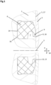
- FIG 3 shows the installation groove 7, which is designed symmetrically but is arranged eccentrically in the sealing arrangement.
- the installation groove 7 is arranged eccentrically displaced in the radial direction 10 in relation to the axis of rotation 3 .
- the 1st sealing lip 9 is arranged concentrically in the installation groove 7, but is shifted eccentrically in relation to the axis of rotation 3 and the sealing surface 8.
Landscapes
- Engineering & Computer Science (AREA)
- General Engineering & Computer Science (AREA)
- Mechanical Engineering (AREA)
- Sealing Devices (AREA)
Abstract
Dichtungsanordnung, umfassend ein erstes Maschinenelement (1) und ein zweites Maschinenelement (2), wobei die Maschinenelemente (1, 2) konzentrisch zueinander angeordnet, um eine Rotationsachse (3) relativ zueinander verdrehbar und einander in axialer Richtung (4) mit Abstand (5) benachbart zugeordnet sind sowie einen Axialdichtring (6), der in einer Einbaunut (7) des ersten Maschinenelements (1) dichtend angeordnet ist und eine Dichtfläche (8) des zweiten Maschinenelements (2) mit zumindest einer Dichtlippe (9) unter axialer Vorspannung dichtend berührt. Die Einbaunut (7) ist, bezogen auf die Rotationsachse (3), in radialer Richtung (10) exzentrisch verschoben angeordnet.
Description
- Die Erfindung betrifft eine Dichtungsanordnung, umfassend ein erstes Maschinenelement und ein zweites Maschinenelement, wobei die Maschinenelemente konzentrisch zueinander angeordnet, um eine Rotationsachse relativ zueinander verdrehbar und einander in axialer Richtung mit Abstand benachbart zugeordnet sind sowie einen Axialdichtring, der in einer Einbaunut des ersten Maschinenelements dichtend angeordnet ist und eine Dichtfläche des zweiten Maschinenelements mit zumindest einer 1. Dichtlippe unter axialer Vorspannung dichtend berührt.
- Eine solche Dichtungsanordnung ist allgemein bekannt.
- Die beiden Maschinenelemente sind in axialer Richtung mit Abstand zueinander benachbart angeordnet, wobei durch den axialen Abstand ein axialer Dichtspalt gebildet ist. Der Axialdichtring ist zum Beispiel durch eine statisch beanspruchte 2. Dichtlippe in der Einbaunut dichtend angeordnet und liegt zum Beispiel mit der dynamisch beanspruchten 1. Dichtlippe an der Dichtfläche dichtend an.
- Die Einbaunut ist, bezogen auf die Rotationsachse, konzentrisch angeordnet, ebenso wie die statisch beanspruchte 2. Dichtlippe und die dynamisch beanspruchte 1. Dichtlippe.
- Während der bestimmungsgemäßen Verwendung der vorbekannten Dichtungsanordnung läuft die dynamisch beanspruchte 1. Dichtlippe des Axialdichtrings deshalb immer auf derselben Laufspur der Dichtfläche. Dabei ist von Nachteil, dass die Schmierung der dynamisch beanspruchten Dichtlippe wenig zufriedenstellend ist, dadurch unerwünscht hohe Temperaturen entstehen und erhöhter Verschleiß, der zu einem frühzeitigen Ausfall des Axialdichtrings und damit der gesamten Dichtungsanordnung führen kann.
- Der Erfindung liegt die Aufgabe zugrunde, eine Dichtungsanordnung der eingangs genannten Art derart weiterzuentwickeln, dass diese gute Gebrauchseigenschaften während einer langen Gebrauchsdauer aufweist. Insbesondere sollen die Gebrauchseigenschaften und die Gebrauchsdauer des Axialdichtrings verbessert werden.
- Diese Aufgabe wird erfindungsgemäß durch eine Dichtungsanordnung mit den Merkmalen von Anspruch 1 gelöst. Auf vorteilhafte Ausgestaltungen nehmen die auf Anspruch 1 direkt oder indirekt rückbezogenen Ansprüche Bezug.
- Zur Lösung der Aufgabe ist es vorgesehen, dass die Einbaunut, bezogen auf die Rotationsachse, in radialer Richtung exzentrisch verschoben angeordnet ist. Hierbei ist von Vorteil, dass die in radialer Richtung exzentrisch zur Rotationsachse verschobene Einbaunut zu einer verbesserten Schmierung der dynamisch beanspruchten 1. Dichtlippe des Axialdichtrings durch eine Verbreiterung der Laufspur der 1. Dichtlippe auf der Dichtfläche führt. Durch die verbesserte Schmierung ist die Wärmeableitung während der bestimmungsgemäßen Verwendung des Axialdichtrings aus der ersten Dichtlippe verbessert und dadurch auch die Gebrauchsdauer des Axialdichtrings und der gesamten Dichtungsanordnung.
- Durch die zuvor beschriebene exzentrisch verschobene Anordnung der Einbaunut bezogen auf die Rotationsachse kann als Axialdichtring ein aus dem Stand der Technik bekannter, konventioneller Axialdichtring zur gegenseitigen Abdichtung der beiden Maschinenelemente zur Anwendung gelangen. Solche konventionellen Axialdichtringe sind in unterschiedlichen Größen und Geometrien und aus unterschiedlichen Werkstoffen kostengünstig verfügbar. Relativ teurer Sonderbauformen, bei denen eine Asymmetrie im Axialdichtring vorgesehen ist, bedarf es daher nicht. Alle Dichtlippen des Axialdichtrings, die statisch beanspruchten und die dynamisch beanspruchten, sind konzentrisch zueinander und symmetrisch ausgebildet.
- Wie zuvor bereits ausgeführt, bewirkt die asymmetrische Verschiebung der Einbaunut in radialer Richtung relativ zur Rotationsachse eine Verbreiterung der Laufspur des Axialdichtrings auf der Dichtfläche des zweiten Maschinenelements. Dadurch gelangt bei jeder Umdrehung des Axialdichtrings relativ zum zweiten Maschinenelement frisches abzudichtendes Medium zur Schmierung aktiv unter die dynamisch beanspruchte, die Dichtfläche berührende 1. Dichtlippe. Diese Dichtlippe läuft immer auf einer durch das abzudichtende Medium frisch geschmierten Laufspur. Die Reibung ist dadurch minimiert und die Wärmeableitung maximiert, so dass der Axialdichtring und die Dichtungsanordnung, die den Axialdichtring umfasst, stets gleichbleibend gute Gebrauchseigenschaften während einer langen Gebrauchsdauer aufweisen.
- Bei dem abzudichtenden Medium handelt es sich bevorzugt um einen Schmierstoff.
- Nach einer vorteilhaften Ausgestaltung kann es vorgesehen sein, dass die exzentrische Verschiebung in radialer Richtung 0,01 mm bis 20 mm, weiter bevorzugt 0,1 mm bis 1 mm beträgt. Für viele Durchmesserbereiche von Axialdichtringen ist eine derartige exzentrische Verschiebung der Einbaunut zielführend, um die zuvor beschriebenen vorteilhaften Gebrauchseigenschaften der Dichtungsanordnung zu erreichen.
- Der Axialdichtring kann einstückig und materialeinheitlich ausgebildet sein. Eine solche Ausgestaltung bewirkt eine einfache und kostengünstige Herstellung. Außerdem ist von Vorteil, dass ein solcher Axialdichtring im Anschluss an seine Verwendung sortenrein recyclebar ist.
- Gemäß einer vorteilhaften Ausgestaltung kann es vorgesehen sein, dass die Dichtlippe des Axialdichtrings symmetrisch ausgebildet ist. Axialdichtringe mit symmetrisch ausgebildeten Dichtlippen sind, wie zuvor beschrieben, allgemein bekannt. Die zuvor beschriebenen vorteilhaften Gebrauchseigenschaften hat der Axialdichtring durch seinen Einbau in die in radialer Richtung exzentrisch zur Rotationsachse verschobene Einbaunut und durch die daraus resultierende Verbreiterung seiner Laufspur auf der Dichtfläche des zweiten Maschinenelements.
- In Abhängigkeit vom jeweiligen Anwendungsfall besteht jedoch auch die Möglichkeit, einen Axialdichtring in der erfindungsgemäßen Dichtungsanordnung zu montieren, bei dem die dynamisch beanspruchte 1. Dichtlippe bezogen auf eine statisch beanspruchte 2. Dichtlippe des Axialdichtrings in radialer Richtung exzentrisch angeordnet ist.
- Dabei kann, je nach Einbau des Axialdichtrings in die Einbaunut in Umfangsrichtung betrachtet, der Effekt der exzentrisch verschoben angeordneten Einbaunut verstärkt oder reduziert werden. Hinsichtlich einer möglichst universellen Verwendbarkeit der Dichtungsanordnung kann das von Vorteil sein.
- Die 1. Dichtlippe kann radial innen- oder radial außendichtend am Axialdichtring angeordnet sein, abhängig vom jeweiligen Anwendungsfall.
- Zwei Ausführungsbeispiele der erfindungsgemäßen Dichtungsanordnung werden nachfolgen anhand der
Figuren 1 bis 3 näher erläutert. - Diese zeigen jeweils in schematischer Darstellung:
-
Figur 1 eine Schnittdarstellung eines ersten Ausführungsbeispiels einer erfindungsgemäßen Dichtungsanordnung, radial innendichtend, -
Figur 2 eine Schnittdarstellung eines zweiten Ausführungsbeispiels einer erfindungsgemäßen Dichtungsanordnung, radial außendichtend, -
Figur 3 eine Ansicht des in der Einbaunut montierten Axialdichtrings, mit eingezeichneter Laufspur auf der Dichtfläche des zweiten Maschinenelements, gemäßFigur 1 . - In den
Figuren 1 bis 3 sind zwei Ausführungsbeispiele der erfindungsgemäßen Dichtungsanordnung gezeigt. - In
Figur 1 ist der Axialdichtring 6 radial innendichtend, inFigur 2 demgegenüber radial außendichtend ausgebildet. - Der Axialdichtring 6 umfasst in diesen Ausführungsbeispielen zwei in axialer Richtung 4 mit Abstand zueinander benachbart angeordnete Stirnseiten 14, 15, wobei die erste Stirnseite 14 eine statisch beanspruchte 2. Dichtlippe 16 und die zweite Stirnseite 15 die dynamisch beanspruchte 1. Dichtlippe 9 aufweist. Der Axialdichtring 6 und die Dichtlippen 9, 16 sind jeweils rotationssymmetrisch ausgebildet.
- Die Dichtungsanordnung umfasst das erste Maschinenelement 1 und das zweite Maschinenelement 2, die konzentrisch zueinander angeordnet und um die Rotationsachse 3 relativ zueinander verdrehbar sind. In axialer Richtung 4 sind sich die Maschinenelemente 1, 2 mit Abstand 5 benachbart zugeordnet, wobei sich durch den Abstand 5 ein abzudichtender Dichtspalt 17 zwischen den Maschinenelementen 1, 2 ergibt.
- Der Axialdichtring 6 ist mit seiner zweiten Dichtlippe 16 in der Einbaunut 7 des ersten Maschinenelements 1 dichtend angeordnet und berührt mit seiner 1. Dichtlippe 9 die Dichtfläche 8 des zweiten Maschinenelements 2 unter axialer Vorspannung dichtend.
- Erfindungsgemäß ist es vorgesehen, dass die Einbaunut 7, bezogen auf die Rotationsachse 3, in radialer Richtung 10 exzentrisch verschoben angeordnet ist.
- Im hier gezeigten Ausführungsbeispiel beträgt die exzentrische Verschiebung der Einbaunut 7 bezogen auf die Rotationsachse 3 etwa 0,5 mm bei einem Durchmesser des Axialdichtrings von etwa 350 mm.
- Die Exzentrizität der Einbaunut 7 in der Dichtungsanordnung bewirkt eine Verbreiterung der Laufspur 18 auf der Dichtfläche 8, die während der bestimmungsgemäßen Verwendung der Dichtungsanordnung von der 1. Dichtlippe 9 des Axialdichtrings 6 überstrichen wird. Bei jeder Umdrehung der Laufspur 18 relativ zur dynamisch beanspruchten 1. Dichtlippe 9 wird diese durch frisches abzudichtendes Medium aktiv geschmiert.
- In
Figur 1 ist die 1. Dichtlippe radial innendichtend, inFigur 2 radial außendichtend am Axialdichtring 6 angeordnet. - In
Figur 3 ist die an sich symmetrisch ausgebildete, aber exzentrisch in der Dichtungsanordnung angeordnete Einbaunut 7 gezeigt. Die Einbaunut 7 ist, bezogen auf die Rotationsachse 3, in radialer Richtung 10 exzentrisch verschoben angeordnet. Die 1. Dichtlippe 9 ist konzentrisch in der Einbaunut 7 angeordnet, bezogen auf die Rotationsachse 3 und die Dichtfläche 8 jedoch exzentrisch verschoben.
Claims (5)
- Dichtungsanordnung, umfassend ein erstes Maschinenelement (1) und ein zweites Maschinenelement (2), wobei die Maschinenelemente (1, 2) konzentrisch zueinander angeordnet, um eine Rotationsachse (3) relativ zueinander verdrehbar und einander in axialer Richtung (4) mit Abstand (5) benachbart zugeordnet sind sowie einen Axialdichtring (6), der in einer Einbaunut (7) des ersten Maschinenelements (1) dichtend angeordnet ist und eine Dichtfläche (8) des zweiten Maschinenelements (2) mit zumindest einer 1. Dichtlippe (9) unter axialer Vorspannung dichtend berührt, dadurch gekennzeichnet, dass die Einbaunut (7), bezogen auf die Rotationsachse (3), in radialer Richtung (10) exzentrisch verschoben angeordnet ist.
- Dichtungsanordnung nach Anspruch 1, dadurch gekennzeichnet, dass die Verschiebung (11) 0,01 mm bis 20 mm beträgt.
- Dichtungsanordnung nach Anspruch 2, dadurch gekennzeichnet, dass die Verschiebung (11) 0,1 mm bis 1 mm beträgt.
- Dichtungsanordnung nach Anspruch 1, dadurch gekennzeichnet, dass die Dichtlippe (9) symmetrisch ausgebildet ist.
- Dichtungsanordnung nach einem der Ansprüche 1 oder 4, dadurch gekennzeichnet, dass die 1. Dichtlippe (9) radial innen- (12) oder radial außendichtend (13) am Axialdichtring (6) angeordnet ist.
Applications Claiming Priority (1)
| Application Number | Priority Date | Filing Date | Title |
|---|---|---|---|
| DE102022105004.1A DE102022105004A1 (de) | 2022-03-03 | 2022-03-03 | Dichtungsanordnung, umfassend einen Axialdichtring |
Publications (1)
| Publication Number | Publication Date |
|---|---|
| EP4239228A1 true EP4239228A1 (de) | 2023-09-06 |
Family
ID=85283944
Family Applications (1)
| Application Number | Title | Priority Date | Filing Date |
|---|---|---|---|
| EP23157341.1A Withdrawn EP4239228A1 (de) | 2022-03-03 | 2023-02-17 | Dichtungsanordnung, umfassend einen axialdichtring |
Country Status (2)
| Country | Link |
|---|---|
| EP (1) | EP4239228A1 (de) |
| DE (1) | DE102022105004A1 (de) |
Citations (3)
| Publication number | Priority date | Publication date | Assignee | Title |
|---|---|---|---|---|
| US3827701A (en) * | 1971-04-08 | 1974-08-06 | Nippon Piston Ring Co Ltd | Oil seal for use in rotary piston internal combustion engine |
| EP0556494A1 (de) * | 1992-02-21 | 1993-08-25 | Gregory H. Petrak | Kassettengleitringdichtung |
| EP1726779A1 (de) * | 2004-03-16 | 2006-11-29 | Daikin Industries, Ltd. | Rotationsexpansionsmaschine |
Family Cites Families (5)
| Publication number | Priority date | Publication date | Assignee | Title |
|---|---|---|---|---|
| GB558544A (en) | 1943-01-01 | 1944-01-10 | Angus George Co Ltd | Improvements in oil seals |
| DE1856354U (de) | 1960-01-20 | 1962-08-09 | Kupfer Asbest Co | Gleitring, insbesondere fuer axial wirkende wellendichtungen. |
| US3825272A (en) | 1971-05-19 | 1974-07-23 | Townsend Engineering Co | Face seal for food processing equipment |
| GB2095347B (en) | 1981-03-23 | 1985-02-20 | Komatsu Mfg Co Ltd | Seals |
| DE29921755U1 (de) | 1999-12-11 | 2001-04-19 | Eduard Küsters, Maschinenfabrik, GmbH & Co. KG, 47805 Krefeld | Gleitringdichtung und damit versehene Walze |
-
2022
- 2022-03-03 DE DE102022105004.1A patent/DE102022105004A1/de not_active Ceased
-
2023
- 2023-02-17 EP EP23157341.1A patent/EP4239228A1/de not_active Withdrawn
Patent Citations (3)
| Publication number | Priority date | Publication date | Assignee | Title |
|---|---|---|---|---|
| US3827701A (en) * | 1971-04-08 | 1974-08-06 | Nippon Piston Ring Co Ltd | Oil seal for use in rotary piston internal combustion engine |
| EP0556494A1 (de) * | 1992-02-21 | 1993-08-25 | Gregory H. Petrak | Kassettengleitringdichtung |
| EP1726779A1 (de) * | 2004-03-16 | 2006-11-29 | Daikin Industries, Ltd. | Rotationsexpansionsmaschine |
Also Published As
| Publication number | Publication date |
|---|---|
| DE102022105004A1 (de) | 2023-09-07 |
Similar Documents
| Publication | Publication Date | Title |
|---|---|---|
| DE2556992C2 (de) | Wellendichtring | |
| DE112018004245B4 (de) | Dichtring | |
| EP1041318B1 (de) | Dichtring | |
| DE2909331C2 (de) | Dichtungsring für Rotationskolbenmaschinen | |
| DE3940003A1 (de) | Kassettendichtung | |
| DE2350630A1 (de) | Hydrodynamische wellendichtung | |
| EP2988035A1 (de) | Dichtring und dessen verwendung | |
| EP1591699B1 (de) | Anordnung mit einem Gehäuse, einer Welle und einem Radialwellendichtring | |
| DE3130760A1 (de) | Dichtungsanordnung | |
| EP4067706A1 (de) | Dichtring | |
| DE102022105004A1 (de) | Dichtungsanordnung, umfassend einen Axialdichtring | |
| DE19726433C2 (de) | Dichtungsanordnung | |
| EP4515126B1 (de) | Radialwellendichtring, radialwellendichtung und radialwellendichtungsanordnung | |
| EP4239229B1 (de) | Axialdichtring | |
| DE102020128146A1 (de) | Dynamische Eingriffsdichtungsvorrichtung und -system mit verbessertem Kontaktverhalten | |
| DE202016104243U1 (de) | Flachdichtung sowie Verbrennungsmotor mit einer derartigen Flachdichtung | |
| WO2024068370A1 (de) | Abgedichtetes axial-radial-gleitlager | |
| DE102019106276A1 (de) | Rotorlagerung einer Windkraftanlage Technisches Gebiet | |
| DE102009024122A1 (de) | Wälzlagerteil, insbesondere Wälzlagerring oder Wälzkörper | |
| EP4483080B1 (de) | Wellendichtring und wellenanordnung für hohe umlaufgeschwindigkeiten | |
| EP1225378B1 (de) | Dichtungsanordnung | |
| DE102020106892B4 (de) | Dichtung und deren Verwendung als Stangen- oder Kolbendichtung | |
| DE4409642C2 (de) | Wellendichtring | |
| DE102023135137A1 (de) | Dichtring | |
| DE102022111599A1 (de) | Dichtring und Dichtungsanordnung, die den Dichtring umfasst |
Legal Events
| Date | Code | Title | Description |
|---|---|---|---|
| PUAI | Public reference made under article 153(3) epc to a published international application that has entered the european phase |
Free format text: ORIGINAL CODE: 0009012 |
|
| STAA | Information on the status of an ep patent application or granted ep patent |
Free format text: STATUS: THE APPLICATION HAS BEEN PUBLISHED |
|
| AK | Designated contracting states |
Kind code of ref document: A1 Designated state(s): AL AT BE BG CH CY CZ DE DK EE ES FI FR GB GR HR HU IE IS IT LI LT LU LV MC ME MK MT NL NO PL PT RO RS SE SI SK SM TR |
|
| STAA | Information on the status of an ep patent application or granted ep patent |
Free format text: STATUS: THE APPLICATION IS DEEMED TO BE WITHDRAWN |
|
| 18D | Application deemed to be withdrawn |
Effective date: 20240307 |