EP4239229B1 - Axialdichtring - Google Patents
Axialdichtring Download PDFInfo
- Publication number
- EP4239229B1 EP4239229B1 EP23157473.2A EP23157473A EP4239229B1 EP 4239229 B1 EP4239229 B1 EP 4239229B1 EP 23157473 A EP23157473 A EP 23157473A EP 4239229 B1 EP4239229 B1 EP 4239229B1
- Authority
- EP
- European Patent Office
- Prior art keywords
- axial
- seal
- sealing lip
- sealing ring
- static seal
- Prior art date
- Legal status (The legal status is an assumption and is not a legal conclusion. Google has not performed a legal analysis and makes no representation as to the accuracy of the status listed.)
- Active
Links
Images


Classifications
-
- F—MECHANICAL ENGINEERING; LIGHTING; HEATING; WEAPONS; BLASTING
- F16—ENGINEERING ELEMENTS AND UNITS; GENERAL MEASURES FOR PRODUCING AND MAINTAINING EFFECTIVE FUNCTIONING OF MACHINES OR INSTALLATIONS; THERMAL INSULATION IN GENERAL
- F16J—PISTONS; CYLINDERS; SEALINGS
- F16J15/00—Sealings
- F16J15/16—Sealings between relatively-moving surfaces
- F16J15/32—Sealings between relatively-moving surfaces with elastic sealings, e.g. O-rings
- F16J15/324—Arrangements for lubrication or cooling of the sealing itself
-
- F—MECHANICAL ENGINEERING; LIGHTING; HEATING; WEAPONS; BLASTING
- F16—ENGINEERING ELEMENTS AND UNITS; GENERAL MEASURES FOR PRODUCING AND MAINTAINING EFFECTIVE FUNCTIONING OF MACHINES OR INSTALLATIONS; THERMAL INSULATION IN GENERAL
- F16J—PISTONS; CYLINDERS; SEALINGS
- F16J15/00—Sealings
- F16J15/16—Sealings between relatively-moving surfaces
- F16J15/32—Sealings between relatively-moving surfaces with elastic sealings, e.g. O-rings
- F16J15/3204—Sealings between relatively-moving surfaces with elastic sealings, e.g. O-rings with at least one lip
- F16J15/3232—Sealings between relatively-moving surfaces with elastic sealings, e.g. O-rings with at least one lip having two or more lips
- F16J15/3236—Sealings between relatively-moving surfaces with elastic sealings, e.g. O-rings with at least one lip having two or more lips with at least one lip for each surface, e.g. U-cup packings
-
- F—MECHANICAL ENGINEERING; LIGHTING; HEATING; WEAPONS; BLASTING
- F16—ENGINEERING ELEMENTS AND UNITS; GENERAL MEASURES FOR PRODUCING AND MAINTAINING EFFECTIVE FUNCTIONING OF MACHINES OR INSTALLATIONS; THERMAL INSULATION IN GENERAL
- F16J—PISTONS; CYLINDERS; SEALINGS
- F16J15/00—Sealings
- F16J15/16—Sealings between relatively-moving surfaces
- F16J15/34—Sealings between relatively-moving surfaces with slip-ring pressed against a more or less radial face on one member
- F16J15/3404—Sealings between relatively-moving surfaces with slip-ring pressed against a more or less radial face on one member and characterised by parts or details relating to lubrication, cooling or venting of the seal
-
- F—MECHANICAL ENGINEERING; LIGHTING; HEATING; WEAPONS; BLASTING
- F16—ENGINEERING ELEMENTS AND UNITS; GENERAL MEASURES FOR PRODUCING AND MAINTAINING EFFECTIVE FUNCTIONING OF MACHINES OR INSTALLATIONS; THERMAL INSULATION IN GENERAL
- F16J—PISTONS; CYLINDERS; SEALINGS
- F16J15/00—Sealings
- F16J15/16—Sealings between relatively-moving surfaces
- F16J15/34—Sealings between relatively-moving surfaces with slip-ring pressed against a more or less radial face on one member
- F16J15/3436—Pressing means
- F16J15/3456—Pressing means without external means for pressing the ring against the face, e.g. slip-ring with a resilient lip
Definitions
- the invention relates to an axial sealing ring comprising two end faces arranged adjacent to one another at a distance from one another in the axial direction, wherein the first end face is designed as an annular static seal and the second end face is designed as an annular dynamic seal with at least one dynamically stressed sealing lip, wherein the dynamic seal is arranged eccentrically in the radial direction with respect to the static seal, with an asymmetric displacement of the dynamically stressed sealing lip with respect to the static seal.
- Axial sealing rings are well known and are used to seal two machine elements against each other.
- the two machine elements are arranged adjacent to each other in the axial direction with a distance between them, whereby the distance forms a sealing gap.
- the two machine elements rotate relative to each other, whereby the axial sealing ring with its static seal is arranged in an installation space of one of the machine elements and the other machine element with the dynamically stressed sealing lip of its dynamically stressed seal is in sealing contact under axial preload.
- the disadvantage here is that the lubrication of the dynamically stressed sealing lip is unsatisfactory, resulting in undesirably high temperatures and increased wear, which can lead to premature failure of the axial sealing ring.
- An axial sealing ring according to the preamble of claim 1 is known from EP 3 508 762 A1 known.
- the axial sealing ring is designed as a cassette seal and comprises a substantially L-shaped flinger ring which is arranged on a shaft in a rotationally fixed manner.
- the shaft and the flinger ring are enclosed on the outer circumference by a housing with a radial spacing, with the sealing ring being arranged in the gap formed by the spacing.
- the sealing ring comprises a substantially L-shaped support ring with a radial and an axial projection which are formed so as to merge into one another in one piece.
- the sealing ring has two dynamically loaded axial sealing lips and a dust lip, each arranged on the radial projection.
- the axial projection is enclosed on the outer circumference by a static seal which seals the sealing ring against the housing.
- the two axial sealing lips are designed to bulge radially outwards from their root area on the radial projection of the support body.
- the slinger forms the raceway for the two axial sealing lips.
- the shaft and the slinger are arranged eccentrically relative to the sealing ring located in the housing.
- the invention is based on the object of further developing an axial sealing ring of the type mentioned above in such a way that it exhibits improved performance characteristics over a longer service life.
- the performance characteristics and service life of the dynamically stressed sealing lip are to be improved.
- the mechanical stress on the sealing lip is to be reduced.
- an axial sealing ring comprising two end faces arranged adjacent to one another at a distance from one another in the axial direction, wherein the first end face is designed as an annular static seal and the second end face is designed as an annular dynamic seal with at least one dynamically stressed sealing lip, wherein the dynamic seal is arranged eccentrically in the radial direction with respect to the static seal, with an asymmetrical displacement of the dynamically stressed sealing lip with respect to the static seal, and wherein the dynamically stressed sealing lip is designed to be curved radially inwards.
- the eccentricity is achieved by asymmetrically displacing the dynamically loaded sealing lip relative to the static seal.
- the advantage here is that the asymmetric geometry of the axial seal ring leads to improved lubrication of the dynamically loaded sealing lip. by widening the track of the sealing lip on a machine element to be sealed. The improved lubrication improves heat dissipation from the sealing lip during the axial seal's intended use, thus extending its service life.
- the annular static seal is manufactured symmetrically, while the dynamically stressed sealing lip, which belongs to the annular dynamic seal, is manufactured asymmetrically.
- the asymmetrical displacement causes a widening of the track.
- the medium to be sealed actively passes under the dynamically loaded sealing lip for lubrication.
- the asymmetrical sealing lip always runs on a track freshly lubricated by the medium to be sealed.
- the medium to be sealed is preferably a lubricant.
- the dynamically loaded sealing lip is designed to be radially inwardly curved. This is an internally sealing variant of the axial sealing ring. As a result, the dynamically loaded sealing lip has a smaller diameter, as if it were radially outwardly curved. Due to the radially inward bulge, the relative circumferential speed of the dynamically loaded sealing lip and the sealing surface of the machine element to be sealed is comparatively low. The mechanical loads on the sealing lip are correspondingly reduced.
- the asymmetrical displacement in the radial direction is 0.01 mm to 20 mm, more preferably 0.1 mm to 1 mm.
- the static and dynamic seals are preferably formed as one piece and made of the same material. This design allows for simple and cost-effective production. Another advantage is that such axial sealing rings can be recycled separately after use.
- the static seal may have at least one statically loaded sealing lip arranged on the side of the static seal axially opposite the dynamic seal.
- the axial seal is arranged under axial preload in its installation space between the machine elements to be sealed against each other.
- the dynamically loaded sealing lip and the statically loaded sealing lip are preferably located approximately in the same axial plane. This prevents tilting moments of the axial seal ring in the installation space.
- the dynamically stressed sealing lip 7 is radially internally sealing.
- the axial sealing ring has two end faces 3, 4 arranged adjacent to each other in the axial direction 1 with a distance 2.
- the first end face 3 is designed as an annular static seal 5, with which the axial sealing ring seals within the installation space 11 of the first machine element 12 (shown in Figure 3 ) is arranged.
- the second end face 4 is designed as an annular dynamic seal 6 and has the dynamically stressed sealing lip 7, which, during the intended use of the axial sealing ring, bears sealingly against the running surface 13 of the second machine element 14 under axial preload.
- the static seal 5 and the dynamic seal 6 are arranged eccentrically to each other in the radial direction 8 by the asymmetrical displacement 9.
- the dynamically loaded sealing lip 7 is actively lubricated during the intended use of the axial seal.
- the eccentricity of the dynamically loaded sealing lip 7 to the static seal 5 causes a widening of the running track 15 on the running surface 13 of the second machine element 14 (shown in the Figures 3 and 4 ), better heat dissipation, less wear and therefore a longer service life of the axial seal.
- the static seal 5 has a statically stressed sealing lip 10 on the side axially facing away from the dynamic seal 6, with which the static seal 5, as in Figure 3 shown, is arranged sealingly within its installation space 11 under elastic axial preload.
- FIG 3 A sealing arrangement is shown in which the axial sealing ring according to the invention is used.
- the first machine element 12 and the second machine element 14 are arranged adjacent to one another in the axial direction 1, with the axial distance forming the sealing gap between the machine elements 12, 14.
- the installation space 11 is a component of the first machine element 12, in which the static seal 5 is sealingly arranged under elastic radial and axial preload.
- the eccentricity of the dynamically loaded sealing lip 7 results in an eccentrically widened track 15 on the running surface 13.
- the medium to be sealed is used for active lubrication of the dynamically loaded sealing lip 7. With each rotation of the dynamically loaded sealing lip 7 on the track 15, the dynamically loaded sealing lip 7 sweeps over a new medium to be sealed.
- the loaded axial sealing ring therefore exhibits consistently good performance characteristics over a long service life.
Landscapes
- Engineering & Computer Science (AREA)
- General Engineering & Computer Science (AREA)
- Mechanical Engineering (AREA)
- Sealing With Elastic Sealing Lips (AREA)
Description
- Die Erfindung betrifft einen Axialdichtring, umfassend zwei in axialer Richtung mit Abstand zueinander benachbart angeordnete Stirnseiten, wobei die erste Stirnseite als ringförmige statische Dichtung und die zweite Stirnseite als ringförmige dynamische Dichtung mit zumindest einer dynamisch beanspruchten Dichtlippe ausgebildet ist, wobei die dynamische Dichtung bezogen auf die statische Dichtung in radialer Richtung exzentrisch angeordnet ist, mit einer asymmetrischen Verschiebung der dynamisch beanspruchten Dichtlippe bezogen auf die statische Dichtung.
- Axialdichtringe sind allgemein bekannt und gelangen zur gegenseitigen Abdichtung von zwei Maschinenelementen zur Anwendung.
- Die beiden Maschinenelemente sind in axialer Richtung mit Abstand zueinander benachbart angeordnet, wobei durch den Abstand ein Dichtspalt gebildet ist. Die beiden Maschinenelemente rotieren relativ zueinander, wobei der Axialdichtring mit seiner statischen Dichtung in einem Einbauraum von einem der Maschinenelemente angeordnet ist und das andere Maschinenelement mit der dynamisch beanspruchten Dichtlippe seiner dynamisch beanspruchten Dichtung unter axialer Vorspannung dichtend berührt.
- Bei Axialdichtringen, bei denen die statische Dichtung und die dynamische Dichtung mit ihrer dynamisch beanspruchten Dichtlippe konzentrisch zueinander angeordnet sind, läuft die dynamisch beanspruchte Dichtlippe während der bestimmungsgemäßen Verwendung deshalb immer auf derselben Laufspur.
- Dabei ist von Nachteil, dass die Schmierung der dynamische beanspruchten Dichtlippe wenig zufriedenstellend ist, dadurch unerwünscht hohe Temperaturen entstehen und erhöhter Verschleiß, der zu einem frühzeitigen Ausfall des Axialdichtrings führen kann.
- Ein Axialdichtring entsprechend dem Oberbegriff von Patentanspruch 1 ist aus der
EP 3 508 762 A1 bekannt. Der Axialdichtring ist als Kassettendichtung ausgebildet und umfasst einen im Wesentlichen L-förmigen Schleuderring, der drehfest auf einer Welle angeordnet ist. Die Welle und der Schleuderring sind außenumfangsseitig von einem Gehäuse mit radialem Abstand umschlossen, wobei in dem durch den Abstand gebildeten Spalt der Dichtring angeordnet ist. Der Dichtring umfasst einen im Wesentlichen L-förmigen Stützring mit einem Radial- und einem Axialvorsprung, die einstückig ineinander übergehend ausgebildet sind. Der Dichtring weist zwei dynamisch beanspruchte Axialdichtlippen und eine Staublippe auf, die jeweils am Radialvorsprung angeordnet sind. Der Axialvorsprung ist außenumfangsseitig von einer statischen Dichtung umschlossen, die den Dichtring gegenüber dem Gehäuse abdichtet. Die beiden Axialdichtlippen sind, ausgehend von ihrem Wurzelbereich, am Radialvorsprung des Stützkörpers radial nach außen vorgewölbt ausgebildet. - Der Schleuderring bildet den Laufring für die beiden Axialdichtlippen. Die Welle und der Schleuderring sind, bezogen auf den im Gehäuse angeordneten Dichtring, exzentrisch zueinander angeordnet.
- Der Erfindung liegt die Aufgabe zu Grunde, einen Axialdichtring der eingangs genannten Art derart weiterzuentwickeln, dass dieser verbesserte Gebrauchseigenschaften während einer längeren Gebrauchsdauer aufweist. Insbesondere sollen die Gebrauchseigenschaften und die Gebrauchsdauer der dynamisch beanspruchten Dichtlippe verbessert werden. Die mechanische Belastung auf die Dichtlippe soll reduziert sein.
- Diese Aufgabe wird erfindungsgemäß durch einen Axialdichtring mit den Merkmalen von Anspruch 1 gelöst. Auf vorteilhafte Ausgestaltungen nehmen die auf Anspruch 1 direkt oder indirekt rückbezogenen Ansprüche Bezug.
- Zur Lösung der Aufgabe ist ein Axialdichtring vorgesehen, umfassend zwei in axialer Richtung mit Abstand zueinander benachbart angeordnete Stirnseiten, wobei die erste Stirnseite als ringförmige statische Dichtung und die zweite Stirnseite als ringförmige dynamische Dichtung mit zumindest einer dynamisch beanspruchten Dichtlippe ausgebildet ist, wobei die dynamische Dichtung bezogen auf die statische Dichtung in radialer Richtung exzentrisch angeordnet ist, mit einer asymmetrischen Verschiebung der dynamisch beanspruchten Dichtlippe bezogen auf die statische Dichtung, und wobei die dynamisch beanspruchte Dichtlippe radial nach innen vorgewölbt ausgebildet ist.
- Die Exzentrizität wird dadurch erreicht, dass die dynamisch beanspruchte Dichtlippe bezogen auf die statische Dichtung asymmetrisch verschoben ist. Hierbei ist von Vorteil, dass die asymmetrische Geometrie des Axialdichtrings zu einer verbesserten Schmierung der dynamisch beanspruchten Dichtlippe durch eine Verbreiterung der Laufspur der Dichtlippe auf einem abzudichtenden Maschinenelement führt. Durch die verbesserte Schmierung ist die Wärmeableitung aus der Dichtlippe während der bestimmungsgemäßen Verwendung des Axialdichtrings verbessert und dadurch die Gebrauchsdauer.
- Die ringförmige statische Dichtung wird symmetrisch hergestellt, die dynamisch beanspruchte Dichtlippe, die zur ringförmigen dynamischen Dichtung gehört, demgegenüber asymmetrisch.
- Wie zuvor bereits ausgeführt, bewirkt die asymmetrische Verschiebung eine Verbreiterung der Laufspur. Dadurch gelangt bei jeder Umdrehung der Dichtlippe relativ zum abzudichtenden Maschinenelement abzudichtendes Medium zur Schmierung aktiv unter die dynamisch beanspruchte Dichtlippe. Die asymmetrische Dichtlippe läuft immer auf einer durch das abzudichtende Medium frisch geschmierten Laufspur.
- Bei dem abzudichtenden Medium handelt es sich bevorzugt um einen Schmierstoff.
- Durch die wesentlich größere Laufspurbreite, bezogen auf symmetrisch ausgebildete Axialdichtringe, und die stets frisch geschmierte Laufspur ist außerdem von Vorteil, dass die Laufspur auf der Lauffläche des abzudichtenden Maschinenelements, auf der die dynamisch beanspruchte Dichtlippe läuft, auch während einer langen Gebrauchsdauer, wenn überhaupt, nur einen sehr geringen Einlauf aufweist.
- Die dynamisch beanspruchte Dichtlippe ist radial nach innen vorgewölbt ausgebildet. Es handelt sich dann um eine innendichtende Variante des Axialdichtrings. Dadurch weist die dynamische beanspruchte Dichtlippe einen kleineren Durchmesser auf, als wäre sie radial nach außen vorgewölbt. Durch die Vorwölbung radial nach innen ist die Umfangsgeschwindigkeit von der dynamisch beanspruchten Dichtlippe und der Dichtfläche des abzudichtenden Maschinenelements relativ zueinander nur vergleichsweise gering. Die mechanischen Belastungen auf die Dichtlippe sind entsprechend reduziert.
- Nach einer vorteilhaften Ausgestaltung kann es vorgesehen sein, dass die asymmetrische Verschiebung in radialer Richtung 0,01 mm bis 20 mm, weiter bevorzugt 0,1 mm bis 1 mm beträgt.
- Für viele Durchmesserbereiche von Axialdichtringen ist eine derartige asymmetrische Verschiebung zielführend, um die zuvor beschriebenen vorteilhaften Gebrauchseigenschaften zu erreichen.
- Die statische und die dynamische Dichtung sind bevorzugt einstückig ineinander übergehend und materialeinheitlich ausgebildet. Eine solche Ausgestaltung bewirkt eine einfache und kostengünstige Herstellung. Außerdem ist von Vorteil, dass solche Axialdichtringe im Anschluss an ihre Verwendung sortenrein recyclebar sind.
- Zur Abdichtung eines Einbauraums, in dem der Axialdichtring eingebaut ist, kann es vorgesehen sein, dass die statische Dichtung zumindest eine statisch beanspruchte Dichtlippe aufweist, die auf der der dynamischen Dichtung axial abgewandten Seite der statischen Dichtung angeordnet ist. Während der bestimmungsgemäßen Verwendung des Axialdichtrings ist dieser unter axialer Vorspannung dichtend in seinem Einbauraum zwischen den gegeneinander abzudichtenden Maschinenelementen angeordnet.
- Die dynamisch beanspruchte Dichtlippe und die statisch beanspruchte Dichtlippe liegen bevorzugt jeweils etwa in derselben Axialebene. Kippmomenten des Axialdichtrings im Einbauraum wird dadurch vorgebeugt.
- Ein Ausführungsbeispiel eines erfindungsgemäßen Axialdichtrings wird nachfolgend anhand der
Figuren 1 bis 4 näher erläutert. - Diese zeigen jeweils in schematischer Darstellung:
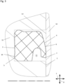
- Figur 1
- eine Schnittdarstellung eines ersten Ausführungsbeispiels des erfindungsgemäßen Axialdichtrings in seinem herstellungsbedingten Zustand,
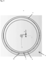
- Figur 2
- eine Ansicht des Axialdichtrings aus
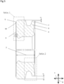
Figur 1 von vorn, - Figur 3
- eine Dichtungsanordnung, in der der Axialdichtring aus
Figur 1 zur Abdichtung von zwei gegeneinander abzudichtenden Maschinenelementen zur Anwendung gelangt, - Figur 4
- eine Ansicht des Axialdichtrings aus den
Figuren 1 und3 von vorn, mit eingezeichneter Laufspur auf der Lauffläche des zweiten Maschinenelements ausFigur 3 , - In den
Figuren 1 bis 4 ist ein erstes Ausführungsbeispiel des erfindungsgemäßen Axialdichtrings gezeigt. - Die dynamisch beanspruchte Dichtlippe 7 ist radial innendichtend.
- Der Axialdichtring hat zwei in axialer Richtung 1 mit Abstand 2 zueinander benachbart angeordnete Stirnseiten 3, 4. Die erste Stirnseite 3 ist als ringförmige statische Dichtung 5 ausgebildet, mit der der Axialdichtring dichtend innerhalb des Einbauraums 11 des ersten Maschinenelements 12 (dargestellt in
Figur 3 ) angeordnet ist. - Die zweite Stirnseite 4 ist demgegenüber als ringförmige dynamische Dichtung 6 ausgebildet und weist die dynamisch beanspruchte Dichtlippe 7 auf, die während der bestimmungsgemäßen Verwendung des Axialdichtrings unter axialer Vorspannung dichtend an der Lauffläche 13 des zweiten Maschinenelements 14 anliegt.
- Im hier gezeigten Ausführungsbeispiel beträgt die asymmetrische Verschiebung 9 von statischer Dichtung 5 und dynamisch beanspruchter Dichtlippe 7 der dynamischen Dichtung 6 relativ zueinander etwa 0,5 mm bei einem Durchmesser des Axialdichtrings von etwa 350 mm.
- Die statische Dichtung 5 und die dynamische Dichtung 6 sind in radialer Richtung 8 um die asymmetrische Verschiebung 9 exzentrisch zueinander angeordnet. Dadurch wird die dynamisch beanspruchte Dichtlippe 7 während der bestimmungsgemäßen Verwendung des Axialdichtrings aktiv geschmiert. Die Exzentrizität der dynamisch beanspruchten Dichtlippe 7 zur statischen Dichtung 5 bewirkt eine Verbreiterung der Laufspur 15 auf der Lauffläche 13 des zweiten Maschinenelements 14 (dargestellt in den
Figuren 3 und4 ), eine bessere Wärmeableitung, weniger Verschleiß und dadurch eine längere Gebrauchsdauer des Axialdichtrings. - Bei jeder Umdrehung der Lauffläche 13 relativ zur dynamisch beanspruchten Dichtlippe 7 wird diese durch neues abzudichtendes Medium auf der verbreiterten Laufspur 15 aktiv geschmiert.
- Die statische Dichtung 5 weist auf der der dynamischen Dichtung 6 axial abgewandten Seite eine statisch beanspruchte Dichtlippe 10 auf, mit der die statische Dichtung 5, wie in
Figur 3 dargestellt, innerhalb ihres Einbauraums 11 unter elastischer axialer Vorspannung dichtend angeordnet ist. - In
Figur 1 ist der Axialdichtring in seiner herstellungsbedingten Form geschnitten dargestellt. - In Kombination mit der Darstellung
Figur 2 , die den Axialdichtring ausFigur 1 in einer Ansicht von rechts zeigt, ist die exzentrische Anordnung der dynamisch beanspruchten Dichtlippe 7 durch die asymmetrische Verschiebung 9 bezogen auf die statische Dichtung 5 gut zu erkennen. - In
Figur 3 ist eine Dichtungsanordnung gezeigt, in der der erfindungsgemäße Axialdichtring zur Anwendung gelangt. Das erste Maschinenelement 12 und das zweite Maschinenelement 14 sind einander in axialer Richtung 1 mit Abstand benachbart zugeordnet, wobei der axiale Abstand den Dichtspalt zwischen den Maschinenelementen 12, 14 bildet. Der Einbauraum 11 ist Bestandteil des ersten Maschinenelements 12, in dem die statische Dichtung 5 unter elastischer radialer und axialer Vorspannung dichtend angeordnet ist. - Die dynamisch beanspruchte Dichtlippe 7, die in radialer Richtung 8 nach innen vorgewölbt ausgebildet ist, berührt die Lauffläche 13 des zweiten Maschinenelements 14 unter elastischer axialer Vorspannung dichtend.
- Durch die Exzentrizität der dynamisch beanspruchten Dichtlippe 7 ergibt sich eine exzentrisch verbreiterte Laufspur 15 auf der Lauffläche 13. Das abzudichtende Medium wird zur aktiven Schmierung der dynamisch beanspruchten Dichtlippe 7 genutzt. Bei jeder Umdrehung der dynamisch beanspruchten Dichtlippe 7 auf der Laufspur 15 überstreicht die dynamisch beanspruchte Dichtlippe 7 neues abzudichtendes Medium. Der beanspruchte Axialdichtring weist deshalb gleichbleibend gute Gebrauchseigenschaften während einer langen Gebrauchsdauer auf.
Claims (5)
- Axialdichtring, umfassend zwei in axialer Richtung (1) mit Abstand (2) zueinander benachbart angeordnete Stirnseiten (3, 4), wobei die erste Stirnseite (3) als ringförmige statische Dichtung (5) und die zweite Stirnseite (4) als ringförmige dynamische Dichtung (6) mit zumindest einer dynamisch beanspruchten Dichtlippe (7) ausgebildet ist, wobei die dynamische Dichtung (6) bezogen auf die statische Dichtung (5) in radialer Richtung (8) exzentrisch angeordnet ist, mit einer asymmetrischen Verschiebung (9) der dynamisch beanspruchten Dichtlippe (7) bezogen auf die statische Dichtung (5), dadurch gekennzeichnet, dass die dynamisch beanspruchte Dichtlippe (7) radial nach innen vorgewölbt ausgebildet ist.
- Axialdichtring nach Anspruch 1, dadurch gekennzeichnet, dass die asymmetrische Verschiebung (9) in radialer Richtung (8) 0,01 mm bis 20 mm beträgt.
- Axialdichtring nach Anspruch 2, dadurch gekennzeichnet, dass die asymmetrische Verschiebung (9) 0,1 mm bis 1 mm beträgt.
- Axialdichtring nach einem der Ansprüche 1 bis 3, dadurch gekennzeichnet, dass die statische (5) und die dynamische Dichtung (6) einstückig ineinander übergehend und materialeinheitlich ausgebildet sind.
- Axialdichtring nach einem der Ansprüche 1 bis 4, dadurch gekennzeichnet, dass die statische Dichtung (5) zumindest eine statisch beanspruchte Dichtlippe (10) aufweist, auf der der dynamischen Dichtlippe (6) axial abgewandten Seite der statischen Dichtung (5).
Applications Claiming Priority (1)
| Application Number | Priority Date | Filing Date | Title |
|---|---|---|---|
| DE102022105003.3A DE102022105003A1 (de) | 2022-03-03 | 2022-03-03 | Axialdichtring |
Publications (2)
| Publication Number | Publication Date |
|---|---|
| EP4239229A1 EP4239229A1 (de) | 2023-09-06 |
| EP4239229B1 true EP4239229B1 (de) | 2025-06-11 |
Family
ID=85285156
Family Applications (1)
| Application Number | Title | Priority Date | Filing Date |
|---|---|---|---|
| EP23157473.2A Active EP4239229B1 (de) | 2022-03-03 | 2023-02-20 | Axialdichtring |
Country Status (2)
| Country | Link |
|---|---|
| EP (1) | EP4239229B1 (de) |
| DE (1) | DE102022105003A1 (de) |
Citations (1)
| Publication number | Priority date | Publication date | Assignee | Title |
|---|---|---|---|---|
| EP3508762A1 (de) * | 2017-08-24 | 2019-07-10 | National University Corporation Saitama University | Dichtungsvorrichtung |
Family Cites Families (7)
| Publication number | Priority date | Publication date | Assignee | Title |
|---|---|---|---|---|
| GB558544A (en) | 1943-01-01 | 1944-01-10 | Angus George Co Ltd | Improvements in oil seals |
| DE1856354U (de) | 1960-01-20 | 1962-08-09 | Kupfer Asbest Co | Gleitring, insbesondere fuer axial wirkende wellendichtungen. |
| US3825272A (en) | 1971-05-19 | 1974-07-23 | Townsend Engineering Co | Face seal for food processing equipment |
| GB2095347B (en) | 1981-03-23 | 1985-02-20 | Komatsu Mfg Co Ltd | Seals |
| EP0508007A1 (de) * | 1991-04-09 | 1992-10-14 | Cooper Industries, Inc. | Dichtungsanordnungen |
| DE4401567C1 (de) * | 1994-01-20 | 1995-02-23 | Heinz Konrad Prof Dr I Mueller | Wellendichtung |
| DE29921755U1 (de) | 1999-12-11 | 2001-04-19 | Eduard Küsters, Maschinenfabrik, GmbH & Co. KG, 47805 Krefeld | Gleitringdichtung und damit versehene Walze |
-
2022
- 2022-03-03 DE DE102022105003.3A patent/DE102022105003A1/de active Pending
-
2023
- 2023-02-20 EP EP23157473.2A patent/EP4239229B1/de active Active
Patent Citations (1)
| Publication number | Priority date | Publication date | Assignee | Title |
|---|---|---|---|---|
| EP3508762A1 (de) * | 2017-08-24 | 2019-07-10 | National University Corporation Saitama University | Dichtungsvorrichtung |
Also Published As
| Publication number | Publication date |
|---|---|
| EP4239229A1 (de) | 2023-09-06 |
| DE102022105003A1 (de) | 2023-09-07 |
Similar Documents
| Publication | Publication Date | Title |
|---|---|---|
| EP0814288B1 (de) | Vorrichtung zur Abdichtung eines Ringspaltes zwischen einem Gehäuse und einer Welle | |
| WO2009103314A1 (de) | Dichtungsanordnung und radialwellendichtring daraus | |
| DE10024026A1 (de) | Dichtmanschette, insbesondere für Einbauräume mit kleinen Abmessungen | |
| DE2556992B1 (de) | Wellendichtring | |
| EP1893877B1 (de) | Wellendichtung | |
| EP4067706B1 (de) | Dichtring | |
| EP4239229B1 (de) | Axialdichtring | |
| DE112005002897T5 (de) | Dichtungsanordnung für ein Wälzlager | |
| EP4515126B1 (de) | Radialwellendichtring, radialwellendichtung und radialwellendichtungsanordnung | |
| DE19726433C2 (de) | Dichtungsanordnung | |
| DE102018101656A1 (de) | Radialwellen-Dichtungsvorrichtung | |
| EP0128241B1 (de) | Dichtung | |
| EP2647889A2 (de) | Dichtungsanordnung | |
| EP1225378B1 (de) | Dichtungsanordnung | |
| DE102022111844B3 (de) | Wellendichtring und Wellenanordnung für hohe Umlaufgeschwindigkeiten | |
| DE69932319T2 (de) | Dichtungsanordnung mit stabilisierten dichtungsringen | |
| DE102018105393B3 (de) | Dichtring und Dichtungsanordnung, die den Dichtring umfasst | |
| EP4239228A1 (de) | Dichtungsanordnung, umfassend einen axialdichtring | |
| DE102021210760A1 (de) | Dichtungsvorrichtung für eine Lagereinheit | |
| DE102014216059A1 (de) | Dichtungsanordnung | |
| EP2861897B2 (de) | Gleitringdichtung | |
| DE102023135137A1 (de) | Dichtring | |
| DE19822356C1 (de) | Gleitringdichtung | |
| DE102021132683A1 (de) | Dichtungsanordnung für einen Wellendichtring und Verfahren zu dessen Herstellung | |
| DE102021206672A1 (de) | Dichtungsvorrichtung für eine Lagereinheit |
Legal Events
| Date | Code | Title | Description |
|---|---|---|---|
| PUAI | Public reference made under article 153(3) epc to a published international application that has entered the european phase |
Free format text: ORIGINAL CODE: 0009012 |
|
| STAA | Information on the status of an ep patent application or granted ep patent |
Free format text: STATUS: THE APPLICATION HAS BEEN PUBLISHED |
|
| AK | Designated contracting states |
Kind code of ref document: A1 Designated state(s): AL AT BE BG CH CY CZ DE DK EE ES FI FR GB GR HR HU IE IS IT LI LT LU LV MC ME MK MT NL NO PL PT RO RS SE SI SK SM TR |
|
| STAA | Information on the status of an ep patent application or granted ep patent |
Free format text: STATUS: REQUEST FOR EXAMINATION WAS MADE |
|
| 17P | Request for examination filed |
Effective date: 20230920 |
|
| RBV | Designated contracting states (corrected) |
Designated state(s): AL AT BE BG CH CY CZ DE DK EE ES FI FR GB GR HR HU IE IS IT LI LT LU LV MC ME MK MT NL NO PL PT RO RS SE SI SK SM TR |
|
| STAA | Information on the status of an ep patent application or granted ep patent |
Free format text: STATUS: EXAMINATION IS IN PROGRESS |
|
| 17Q | First examination report despatched |
Effective date: 20240226 |
|
| GRAP | Despatch of communication of intention to grant a patent |
Free format text: ORIGINAL CODE: EPIDOSNIGR1 |
|
| STAA | Information on the status of an ep patent application or granted ep patent |
Free format text: STATUS: GRANT OF PATENT IS INTENDED |
|
| INTG | Intention to grant announced |
Effective date: 20250114 |
|
| GRAS | Grant fee paid |
Free format text: ORIGINAL CODE: EPIDOSNIGR3 |
|
| GRAA | (expected) grant |
Free format text: ORIGINAL CODE: 0009210 |
|
| STAA | Information on the status of an ep patent application or granted ep patent |
Free format text: STATUS: THE PATENT HAS BEEN GRANTED |
|
| AK | Designated contracting states |
Kind code of ref document: B1 Designated state(s): AL AT BE BG CH CY CZ DE DK EE ES FI FR GB GR HR HU IE IS IT LI LT LU LV MC ME MK MT NL NO PL PT RO RS SE SI SK SM TR |
|
| REG | Reference to a national code |
Ref country code: GB Ref legal event code: FG4D Free format text: NOT ENGLISH |
|
| REG | Reference to a national code |
Ref country code: CH Ref legal event code: EP |
|
| REG | Reference to a national code |
Ref country code: DE Ref legal event code: R096 Ref document number: 502023001112 Country of ref document: DE |
|
| REG | Reference to a national code |
Ref country code: IE Ref legal event code: FG4D Free format text: LANGUAGE OF EP DOCUMENT: GERMAN |
|
| P01 | Opt-out of the competence of the unified patent court (upc) registered |
Free format text: CASE NUMBER: APP_26723/2025 Effective date: 20250605 |
|
| PG25 | Lapsed in a contracting state [announced via postgrant information from national office to epo] |
Ref country code: FI Free format text: LAPSE BECAUSE OF FAILURE TO SUBMIT A TRANSLATION OF THE DESCRIPTION OR TO PAY THE FEE WITHIN THE PRESCRIBED TIME-LIMIT Effective date: 20250611 Ref country code: ES Free format text: LAPSE BECAUSE OF FAILURE TO SUBMIT A TRANSLATION OF THE DESCRIPTION OR TO PAY THE FEE WITHIN THE PRESCRIBED TIME-LIMIT Effective date: 20250611 |
|
| REG | Reference to a national code |
Ref country code: LT Ref legal event code: MG9D |
|
| PG25 | Lapsed in a contracting state [announced via postgrant information from national office to epo] |
Ref country code: GR Free format text: LAPSE BECAUSE OF FAILURE TO SUBMIT A TRANSLATION OF THE DESCRIPTION OR TO PAY THE FEE WITHIN THE PRESCRIBED TIME-LIMIT Effective date: 20250912 Ref country code: NO Free format text: LAPSE BECAUSE OF FAILURE TO SUBMIT A TRANSLATION OF THE DESCRIPTION OR TO PAY THE FEE WITHIN THE PRESCRIBED TIME-LIMIT Effective date: 20250911 |
|
| REG | Reference to a national code |
Ref country code: NL Ref legal event code: MP Effective date: 20250611 |
|
| PG25 | Lapsed in a contracting state [announced via postgrant information from national office to epo] |
Ref country code: BG Free format text: LAPSE BECAUSE OF FAILURE TO SUBMIT A TRANSLATION OF THE DESCRIPTION OR TO PAY THE FEE WITHIN THE PRESCRIBED TIME-LIMIT Effective date: 20250611 |
|
| PG25 | Lapsed in a contracting state [announced via postgrant information from national office to epo] |
Ref country code: HR Free format text: LAPSE BECAUSE OF FAILURE TO SUBMIT A TRANSLATION OF THE DESCRIPTION OR TO PAY THE FEE WITHIN THE PRESCRIBED TIME-LIMIT Effective date: 20250611 |
|
| PG25 | Lapsed in a contracting state [announced via postgrant information from national office to epo] |
Ref country code: RS Free format text: LAPSE BECAUSE OF FAILURE TO SUBMIT A TRANSLATION OF THE DESCRIPTION OR TO PAY THE FEE WITHIN THE PRESCRIBED TIME-LIMIT Effective date: 20250911 |
|
| PG25 | Lapsed in a contracting state [announced via postgrant information from national office to epo] |
Ref country code: LV Free format text: LAPSE BECAUSE OF FAILURE TO SUBMIT A TRANSLATION OF THE DESCRIPTION OR TO PAY THE FEE WITHIN THE PRESCRIBED TIME-LIMIT Effective date: 20250611 |
|
| PG25 | Lapsed in a contracting state [announced via postgrant information from national office to epo] |
Ref country code: NL Free format text: LAPSE BECAUSE OF FAILURE TO SUBMIT A TRANSLATION OF THE DESCRIPTION OR TO PAY THE FEE WITHIN THE PRESCRIBED TIME-LIMIT Effective date: 20250611 |
|
| PG25 | Lapsed in a contracting state [announced via postgrant information from national office to epo] |
Ref country code: PT Free format text: LAPSE BECAUSE OF FAILURE TO SUBMIT A TRANSLATION OF THE DESCRIPTION OR TO PAY THE FEE WITHIN THE PRESCRIBED TIME-LIMIT Effective date: 20251013 |
|
| PG25 | Lapsed in a contracting state [announced via postgrant information from national office to epo] |
Ref country code: IS Free format text: LAPSE BECAUSE OF FAILURE TO SUBMIT A TRANSLATION OF THE DESCRIPTION OR TO PAY THE FEE WITHIN THE PRESCRIBED TIME-LIMIT Effective date: 20251011 |
|
| PG25 | Lapsed in a contracting state [announced via postgrant information from national office to epo] |
Ref country code: SM Free format text: LAPSE BECAUSE OF FAILURE TO SUBMIT A TRANSLATION OF THE DESCRIPTION OR TO PAY THE FEE WITHIN THE PRESCRIBED TIME-LIMIT Effective date: 20250611 |
|
| PG25 | Lapsed in a contracting state [announced via postgrant information from national office to epo] |
Ref country code: CZ Free format text: LAPSE BECAUSE OF FAILURE TO SUBMIT A TRANSLATION OF THE DESCRIPTION OR TO PAY THE FEE WITHIN THE PRESCRIBED TIME-LIMIT Effective date: 20250611 |
|
| PG25 | Lapsed in a contracting state [announced via postgrant information from national office to epo] |
Ref country code: PL Free format text: LAPSE BECAUSE OF FAILURE TO SUBMIT A TRANSLATION OF THE DESCRIPTION OR TO PAY THE FEE WITHIN THE PRESCRIBED TIME-LIMIT Effective date: 20250611 |
|
| PG25 | Lapsed in a contracting state [announced via postgrant information from national office to epo] |
Ref country code: EE Free format text: LAPSE BECAUSE OF FAILURE TO SUBMIT A TRANSLATION OF THE DESCRIPTION OR TO PAY THE FEE WITHIN THE PRESCRIBED TIME-LIMIT Effective date: 20250611 |
|
| PG25 | Lapsed in a contracting state [announced via postgrant information from national office to epo] |
Ref country code: SK Free format text: LAPSE BECAUSE OF FAILURE TO SUBMIT A TRANSLATION OF THE DESCRIPTION OR TO PAY THE FEE WITHIN THE PRESCRIBED TIME-LIMIT Effective date: 20250611 |
|
| PG25 | Lapsed in a contracting state [announced via postgrant information from national office to epo] |
Ref country code: DK Free format text: LAPSE BECAUSE OF FAILURE TO SUBMIT A TRANSLATION OF THE DESCRIPTION OR TO PAY THE FEE WITHIN THE PRESCRIBED TIME-LIMIT Effective date: 20250611 |
|
| PGFP | Annual fee paid to national office [announced via postgrant information from national office to epo] |
Ref country code: DE Payment date: 20260220 Year of fee payment: 4 |
|
| PGFP | Annual fee paid to national office [announced via postgrant information from national office to epo] |
Ref country code: AT Payment date: 20260301 Year of fee payment: 4 |
|
| PG25 | Lapsed in a contracting state [announced via postgrant information from national office to epo] |
Ref country code: IT Free format text: LAPSE BECAUSE OF FAILURE TO SUBMIT A TRANSLATION OF THE DESCRIPTION OR TO PAY THE FEE WITHIN THE PRESCRIBED TIME-LIMIT Effective date: 20250611 |
|
| PLBE | No opposition filed within time limit |
Free format text: ORIGINAL CODE: 0009261 |
|
| STAA | Information on the status of an ep patent application or granted ep patent |
Free format text: STATUS: NO OPPOSITION FILED WITHIN TIME LIMIT |
|
| REG | Reference to a national code |
Ref country code: CH Ref legal event code: L10 Free format text: ST27 STATUS EVENT CODE: U-0-0-L10-L00 (AS PROVIDED BY THE NATIONAL OFFICE) Effective date: 20260423 |