EP3508762A1 - Sealing device - Google Patents
Sealing device Download PDFInfo
- Publication number
- EP3508762A1 EP3508762A1 EP18848886.0A EP18848886A EP3508762A1 EP 3508762 A1 EP3508762 A1 EP 3508762A1 EP 18848886 A EP18848886 A EP 18848886A EP 3508762 A1 EP3508762 A1 EP 3508762A1
- Authority
- EP
- European Patent Office
- Prior art keywords
- rotating
- rotating shaft
- sealing device
- target
- force
- Prior art date
- Legal status (The legal status is an assumption and is not a legal conclusion. Google has not performed a legal analysis and makes no representation as to the accuracy of the status listed.)
- Withdrawn
Links
Images


Classifications
-
- F—MECHANICAL ENGINEERING; LIGHTING; HEATING; WEAPONS; BLASTING
- F16—ENGINEERING ELEMENTS AND UNITS; GENERAL MEASURES FOR PRODUCING AND MAINTAINING EFFECTIVE FUNCTIONING OF MACHINES OR INSTALLATIONS; THERMAL INSULATION IN GENERAL
- F16C—SHAFTS; FLEXIBLE SHAFTS; ELEMENTS OR CRANKSHAFT MECHANISMS; ROTARY BODIES OTHER THAN GEARING ELEMENTS; BEARINGS
- F16C11/00—Pivots; Pivotal connections
- F16C11/04—Pivotal connections
- F16C11/06—Ball-joints; Other joints having more than one degree of angular freedom, i.e. universal joints
- F16C11/0666—Sealing means between the socket and the inner member shaft
-
- F—MECHANICAL ENGINEERING; LIGHTING; HEATING; WEAPONS; BLASTING
- F16—ENGINEERING ELEMENTS AND UNITS; GENERAL MEASURES FOR PRODUCING AND MAINTAINING EFFECTIVE FUNCTIONING OF MACHINES OR INSTALLATIONS; THERMAL INSULATION IN GENERAL
- F16J—PISTONS; CYLINDERS; SEALINGS
- F16J15/00—Sealings
- F16J15/16—Sealings between relatively-moving surfaces
- F16J15/32—Sealings between relatively-moving surfaces with elastic sealings, e.g. O-rings
- F16J15/3204—Sealings between relatively-moving surfaces with elastic sealings, e.g. O-rings with at least one lip
- F16J15/3232—Sealings between relatively-moving surfaces with elastic sealings, e.g. O-rings with at least one lip having two or more lips
-
- F—MECHANICAL ENGINEERING; LIGHTING; HEATING; WEAPONS; BLASTING
- F16—ENGINEERING ELEMENTS AND UNITS; GENERAL MEASURES FOR PRODUCING AND MAINTAINING EFFECTIVE FUNCTIONING OF MACHINES OR INSTALLATIONS; THERMAL INSULATION IN GENERAL
- F16C—SHAFTS; FLEXIBLE SHAFTS; ELEMENTS OR CRANKSHAFT MECHANISMS; ROTARY BODIES OTHER THAN GEARING ELEMENTS; BEARINGS
- F16C11/00—Pivots; Pivotal connections
- F16C11/04—Pivotal connections
- F16C11/06—Ball-joints; Other joints having more than one degree of angular freedom, i.e. universal joints
-
- F—MECHANICAL ENGINEERING; LIGHTING; HEATING; WEAPONS; BLASTING
- F16—ENGINEERING ELEMENTS AND UNITS; GENERAL MEASURES FOR PRODUCING AND MAINTAINING EFFECTIVE FUNCTIONING OF MACHINES OR INSTALLATIONS; THERMAL INSULATION IN GENERAL
- F16J—PISTONS; CYLINDERS; SEALINGS
- F16J15/00—Sealings
- F16J15/16—Sealings between relatively-moving surfaces
- F16J15/32—Sealings between relatively-moving surfaces with elastic sealings, e.g. O-rings
- F16J15/3204—Sealings between relatively-moving surfaces with elastic sealings, e.g. O-rings with at least one lip
- F16J15/3224—Sealings between relatively-moving surfaces with elastic sealings, e.g. O-rings with at least one lip capable of accommodating changes in distances or misalignment between the surfaces, e.g. able to compensate for defaults of eccentricity or angular deviations
-
- F—MECHANICAL ENGINEERING; LIGHTING; HEATING; WEAPONS; BLASTING
- F16—ENGINEERING ELEMENTS AND UNITS; GENERAL MEASURES FOR PRODUCING AND MAINTAINING EFFECTIVE FUNCTIONING OF MACHINES OR INSTALLATIONS; THERMAL INSULATION IN GENERAL
- F16J—PISTONS; CYLINDERS; SEALINGS
- F16J15/00—Sealings
- F16J15/16—Sealings between relatively-moving surfaces
- F16J15/32—Sealings between relatively-moving surfaces with elastic sealings, e.g. O-rings
- F16J15/3248—Sealings between relatively-moving surfaces with elastic sealings, e.g. O-rings provided with casings or supports
- F16J15/3252—Sealings between relatively-moving surfaces with elastic sealings, e.g. O-rings provided with casings or supports with rigid casings or supports
-
- F—MECHANICAL ENGINEERING; LIGHTING; HEATING; WEAPONS; BLASTING
- F16—ENGINEERING ELEMENTS AND UNITS; GENERAL MEASURES FOR PRODUCING AND MAINTAINING EFFECTIVE FUNCTIONING OF MACHINES OR INSTALLATIONS; THERMAL INSULATION IN GENERAL
- F16J—PISTONS; CYLINDERS; SEALINGS
- F16J15/00—Sealings
- F16J15/16—Sealings between relatively-moving surfaces
- F16J15/34—Sealings between relatively-moving surfaces with slip-ring pressed against a more or less radial face on one member
- F16J15/3404—Sealings between relatively-moving surfaces with slip-ring pressed against a more or less radial face on one member and characterised by parts or details relating to lubrication, cooling or venting of the seal
-
- F—MECHANICAL ENGINEERING; LIGHTING; HEATING; WEAPONS; BLASTING
- F16—ENGINEERING ELEMENTS AND UNITS; GENERAL MEASURES FOR PRODUCING AND MAINTAINING EFFECTIVE FUNCTIONING OF MACHINES OR INSTALLATIONS; THERMAL INSULATION IN GENERAL
- F16J—PISTONS; CYLINDERS; SEALINGS
- F16J15/00—Sealings
- F16J15/16—Sealings between relatively-moving surfaces
- F16J15/34—Sealings between relatively-moving surfaces with slip-ring pressed against a more or less radial face on one member
- F16J15/3436—Pressing means
- F16J15/3456—Pressing means without external means for pressing the ring against the face, e.g. slip-ring with a resilient lip
Definitions
- the present invention relates to a sealing device which suppresses leakage of a sealing target or the entrance of foreign matter via a shaft circumference of a rotating shaft due to a contacting target portion of a lip portion or the like being pushed against a rotating surface to contact and slide on the rotating surface.
- Patent Literature 1 An oil seal which is disclosed in Patent Literature 1 or the like is an example of this type of sealing device in the related art.
- the oil seal is a functional component which is used in many devices with the object of keeping a sealing fluid inside an apparatus and suppressing the entrance of foreign matter originating from outside of the apparatus into the apparatus.
- the present invention is provided in order to solve the problem and is a sealing device including a rotating shaft which rotates centered on an axial center, a rotating member which includes a rotating surface, which projects in a direction which orthogonally intersects the axial center and surrounds an outer circumference of the rotating shaft, and rotates together with the rotating shaft, and a fixing member which includes a contacting target portion which is provided in a non-rotating state to surround an outer circumference of the rotating shaft and face the rotating surface, receives a biasing force in an axial direction of the rotating shaft to contact the rotating surface, slides on the rotating surface due to the rotating shaft rotating, and rotates relative to the rotating shaft, in which the sealing device suppresses leakage of a sealing target or entrance of foreign matter via a shaft circumference of the rotating shaft due to the contacting target portion being pushed against the rotating surface and contacting and sliding on the rotating surface, and in which in the fixing member, a relative rotational center of the contacting target portion is disposed to be eccentric with respect to a rotational center of the
- the restoring force and the restoring direction component of the friction force which acts on the contacting target portion are autonomously stabilized to assume an equalized state, friction vibration is no longer generated by the friction which is generated between the rotating surface and the contacting target portion, and the stick-slipping is eliminated.
- the rotating member is a slinger which includes a flange surface as the rotating surface and is fixed to the rotating shaft
- the fixing member includes a lip portion, a distal end portion of which contacts and slides on the flange surface as the contacting target portion, which exhibits, as the biasing force, an elastic force for pushing the distal end portion against the flange surface, and a metal ring which supports the lip portion
- the sealing device is configured from an oil seal which suppresses leakage of a sealing target or entrance of foreign matter via a shaft circumference of the rotating shaft due to the distal end portion of the lip portion being pushed against the flange surface to contact and slide on the flange surface.
- a rotational drive component which orthogonally intersects the restoring direction of the restoring force is applied to the lip portion from the flange surface of the slinger due to the relative rotational center of the lip portion being disposed to be eccentric in relation to the rotational center of the slinger and the lip portion receiving a rotational drive force from the slinger in a direction which intersects a restoring direction of the restoring force in a predetermined angle range. Therefore, the restoring force and the restoring direction component of the friction force which acts on the lip portion are autonomously stabilized to assume an equalized state, friction vibration is no longer generated by the friction which is generated between the flange surface of the slinger and the lip portion, and the stick-slipping is eliminated from the oil seal.
- the rotating shaft includes a sealing portion which is axially sealed
- the rotating member is a slinger which includes a flange surface as the rotating surface and is fixed to the rotating shaft in a vicinity of the sealing portion
- the fixing member includes a lip portion which has a skirt-shape in which a diameter spreads from the sealing portion toward the flange surface, a distal end portion of the lip portion contacts and slides on the flange surface as the contacting target portion, and exhibits, as the biasing force, an elastic force for pushing the distal end portion against the flange surface
- the sealing device suppresses, together with the sealing portion, leakage of a sealing target or entrance of foreign matter via a shaft circumference of the rotating shaft due to the distal end portion of the lip portion being pushed against the flange surface to contact and slide on the flange surface.
- a rotational drive component which orthogonally intersects the restoring direction of the restoring force is applied to the lip portion from the flange surface of the slinger due to the relative rotational center of the lip portion which has a skirt shape being disposed to be eccentric in relation to the rotational center of the slinger and the lip portion receiving a rotational drive force from the slinger in a direction which intersects a restoring direction of the restoring force in a predetermined angle range.
- the restoring force and the restoring direction component of the friction force which acts on the lip portion are autonomously stabilized to assume an equalized state, friction vibration is no longer generated by the friction which is generated between the flange surface of the slinger and the lip portion, and the stick-slipping which occurs in the skirt-shaped lip portion is eliminated.
- the rotating member includes a rotating ring which includes a rotating ring-shaped end surface which orthogonally intersects an axial center of the rotating shaft as the rotating surface, is fixed to the rotating shaft, and is rigid
- the fixing member includes a static annular surface which faces the rotating ring-shaped end surface as the contacting target portion, includes a fixed ring in which the static annular surface contacts and slides on the rotating ring-shaped end surface, and is rigid
- the sealing device further includes an elastic body which exhibits, as the biasing force, an elastic force for pushing the static annular surface of the fixed ring against the rotating ring-shaped end surface of the rotating ring, and the sealing device is configured from a mechanical seal which suppresses leakage of a sealing target or entrance of foreign matter via a shaft circumference of the rotating shaft due to the static annular surface of the fixed ring being pushed against the rotating ring-shaped end surface of the rotating ring to contact and slide on the rotating ring-shaped end surface.
- a rotational drive component which orthogonally intersects the restoring direction of the restoring force is applied to the static annular surface of the fixed ring from the rotating ring-shaped end surface of the rotating ring due to the relative rotational center of the static annular surface in the fixed ring being disposed to be eccentric in relation to the rotational center of the rotating ring and the static annular surface receiving a rotational drive force from the rotating ring in a direction which intersects a restoring direction of the restoring force in a predetermined angle range.
- the restoring force and the restoring direction component of the friction force which acts on the static annular surface of the fixed ring are autonomously stabilized to assume an equalized state, friction vibration is no longer generated by the friction which is generated between the rotating ring-shaped end surface of the rotating ring and the static annular surface of the fixed ring, and the stick-slipping is eliminated from the mechanical seal.
- the sealing device further includes a dust cover which includes a trunk portion which has deformable elasticity, a fixing target portion which is provided to one end side of the trunk portion and is fixed to a socket which supports a ball stud to rotate and rock freely, and a seal portion which is provided on another end side of the trunk portion to slide freely with respect to each of a shaft portion of the ball stud having a spherical portion on one end and an attaching target portion of the ball stud, in which the rotating shaft is the ball stud, in which the rotating member is the attaching target portion which includes an attaching target surface as the rotating surface and is fixed to a shaft portion of the ball stud, in which the fixing member is an elastic seal main body which is provided with a dust lip which contacts the attaching target surface as the contacting target portion and is provided on the seal portion, and in which the sealing device suppresses leakage of a sealing target from a ball joint portion or entrance of foreign matter to the ball joint portion via a shaft circumference of the ball stud due to the dust
- a rotational drive component which orthogonally intersects the restoring direction of the restoring force is applied to the dust lip from the attaching target surface of the attaching target portion due to the relative rotational center of the dust lip being disposed to be eccentric in relation to the rotational center of the attaching target portion and the dust lip receiving a rotational drive force from the attaching target portion in a direction which intersects a restoring direction of the restoring force in a predetermined angle range.
- the restoring force and the restoring direction component of the friction force which acts on the dust lip are autonomously stabilized to assume an equalized state, friction vibration is no longer generated by the friction which is generated between the attaching target surface of the attaching target portion and the dust lip, and the stick-slipping which occurs in the seal portion of the dust cover is eliminated.
- the predetermined angle range is a range indicated by an inequality expression 0 ⁇
- the rotational drive component which orthogonally intersects the restoring direction of the restoring force becomes non-zero and is applied to the contacting target portion of the fixing member from the rotating surface of the rotating member, and the attenuation manifests in the friction vibration originating in the side-slipping drive component. Therefore, the friction vibration which is generated by the friction which is generated between the rotating surface of the rotating member and the contacting target portion of the fixing member is suppressed and the stick-slipping is eliminated.
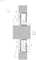
- Fig. 1 is a sectional diagram of a sealing device 1A according to the first embodiment of the present invention.
- the sealing device 1A is configured to include a rotating shaft 11A which rotates centered on an axial center A, a slinger 21A which is a rotating member which is fixed to the rotating shaft 11A and rotates together with the rotating shaft 11A, and a fixing member 31A which rotates relative to the rotating shaft 11A.
- An outer circumference of the fixing member 31A is fitted into a housing 41A to fix the fixing member 31A to the housing 41A.
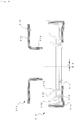
- Fig. 2 is a sectional diagram distinctly illustrating each of the slinger 21A and the fixing member 31A in which the sealing device 1A illustrated in Fig. 1 is removed from the housing 41A and the rotating shaft 11A is taken out.
- the slinger 21A is produced by punching and press-forming a metal plate and includes a cylinder portion 21a which is pressure fitted to the outer circumferential surface of the rotating shaft 11A and a flange portion 21b which extends in a disc shape in an outward radial direction from the cylinder portion 21a.
- the flange portion 21b includes, as a rotating surface, a flange surface 21b1 which projects in a direction orthogonally intersecting the axial center A of the rotating shaft 11A to surround the outer circumference of the rotating shaft 11A.
- the fixing member 31A is obtained by integrally molding a rubber elastic material as a lip portion on a metal ring 31a which is produced by punching and press-forming a metal plate.
- the lip portion is supported by the metal ring 31a.
- the grease lip portions 31b exhibit an elastic force for pushing the distal end portions of the grease lip portions 31b against the flange surface 21b1, and the distal end portions receive a biasing force in an axial direction of the rotating shaft 11A to flex as illustrated in Fig. 1 .
- the distal end portions of the grease lip portions 31b receive the biasing force in the axial direction of the rotating shaft 11A and contact the flange surface 21b1 as contacting target portions 31b1.
- the contacting target portions 31b1 surround the outer circumference of the rotating shaft 11A to face the flange surface 21b1 and are provided in a non-rotating state due to the fixing member 31A being supported by the housing 41A.
- the contacting target portions 31b1 slide on the flange surface 21b1 due to the rotating shaft 11A rotating and the contacting target portions 31b1 rotate relative to the flange surface 21b1.
- the sealing device 1A suppresses the leakage of a sealing target or the entrance of foreign matter via the shaft circumference of the rotating shaft 11A due to the distal end portions of the grease lip portions 31b being pushed against the flange surface 21b1 to contact and slide on the flange surface 21b1.
- the sealing device 1A is used as a hub bearing seal or an oil seal, for example.
- the annular shape of the grease lip portions 31b is not symmetrical to the relative rotational center of the fixing member 31A and is formed asymmetrically. Therefore, a relative rotational center B of the contacting target portions 31b1 of the grease lip portions 31b is disposed to be eccentric by an interval of a distance ⁇ with respect to the rotational center A of the rotating shaft 11A.
- torsion is generated by the friction force F and a restoring force which is centered on the relative rotational center B acts on the contacting target portions 31b1 against the torsion.
- the contacting target portions 31b1 receive a rotational drive force from the flange surface 21b1 of the slinger 21A in a direction which intersects the restoring direction of the restoring force in a predetermined angle range and a rotational drive component which orthogonally intersects the restoring direction of the restoring force is applied to the contacting target portions 31b1 from the flange surface 21b1.
- of the angle ⁇ (the misalignment angle) which is formed by the rotational drive direction ⁇ with the restoring direction ⁇ of the restoring force is set in a predetermined angle range indicated by inequality expression 0 ⁇
- a restoring direction component Fcos ⁇ of the friction force F which acts on the contacting target portions 31b1 of the grease lip portions 31b and the restoring force which is exhibited by the housing 41A are autonomously stabilized to assume an equalized state, and friction vibration is no longer generated by the friction which is generated between the flange surface 21b1 of the slinger 21A and the contacting target portions 31b1 of the grease lip portions 31b.
- ⁇ is an angle formed by a relative velocity Vrel with respect to the restoring direction ⁇ of the restoring force, the relative velocity Vrel being between the rotation drive velocity V of the flange surface 21b1 and the restoring velocity v of the restoring force which is applied to the contacting target portions 31b1 of the grease lip portions 31b from the housing 41A.
- the restoring velocity v of the restoring force is represented by a first-order differentiation x' of a displacement amount x by which the contacting target portions 31b1 are displaced in a circumferential direction corresponding to the torsion.
- the angle which the friction force F forms with respect to the restoring direction ⁇ of the restoring force is also ⁇ .
- the rotational drive component Vsin ⁇ which orthogonally intersects the restoring direction ⁇ of the restoring force is applied to the toric contacting target portions 31b1 from the flange surface 21b1.
- the misalignment angle ⁇ which is formed between the rotational drive direction ⁇ and the restoring direction ⁇ is set in a range of 0 ⁇
- the restoring direction component Fcos ⁇ of the friction force F which acts on the contacting target portions 31b1 of the grease lip portions 31b and the restoring force which is exhibited by the housing 41A are autonomously stabilized to assume an equalized state, and the friction vibration is no longer generated by the friction which is generated between the flange surface 21b1 of the slinger 21A and the contacting target portions 31b1 of the grease lip portions 31b.
- Figs. 4A and 4B are a plan view and a side view for explaining the sealing principle of the sealing device 1A of the present embodiment.
- Figs. 4A and 4B schematically represent the slipping friction between a sphere 5 and a plate 6. It is possible to apply the principle described hereinafter to the sealing principle of the sealing device 1A of the present embodiment by adapting the sphere 5 to the grease lip portions 31b of the present embodiment and adapting the plate 6 to the flange surface 21b1.
- the sphere 5 having a mass m is attached to a right end of a spring 8 having a rigidity k which is fixed to a static wall 7 by a left end of the spring 8.
- the motion of the sphere 5 is only allowed as translation in a bending direction (an x-direction) of the spring 8.
- the plate 6 contacts the sphere 5 with a perpendicular load W and moves linearly at the drive velocity V to form a misalignment angle ⁇ with the x-direction.
- the motion velocity of the sphere 5 may be represented as x' using a differentiation (') which is related to t.
- the relative velocity Vrel between the drive velocity V of the plate 6 and the motion velocity x' of the sphere 5 is set to ⁇
- the friction force F which acts on the sphere 5 acts in a direction which reduces the relative velocity Vrel
- the angle which the friction force F forms with the x-direction also becomes ⁇ .
- the relative velocity Vrel has a non-zero lateral sliding component Vsin ⁇ and the orientation of the friction force F changes according to the change in the motion velocity x'.
- Equation (7) A disturbance x ⁇ from the equilibrium point x eq is provided using the following Equation (6) in order to consider the stability of the equilibrium point x eq .
- x x eq + x ⁇
- Equation (7) may be obtained.
- coefficients c 1 and c 2 of (x ⁇ )' of the second term on the left are the following Equations (8) and (9).
- c 1 ⁇ ′ V ⁇ W ⁇ cos 2 ⁇
- c 2 ⁇ V ⁇ W / V ⁇ sin 2 ⁇
- the coefficient c 1 represents a viscosity attenuation which is exhibited according to a relative velocity dependence of the friction coefficient, and the coefficient c 2 represents the viscosity attenuation which is exhibited by providing the non-zero misalignment angle ⁇ (the lateral sliding component Vsin ⁇ ).
- Equation (7) is a second-order linear ordinary differential equation
- the stability of the equilibrium point x eq is determined by the sign of the coefficients of (x ⁇ )'.
- Expression (10) c 1 + c 2 > 0 is true
- the equilibrium point x eq becomes stable.
- Expressions (8) to (10) are organized, the following inequality expression of Expression (11) is finally obtained as the stability condition of the equilibrium point x eq .
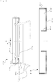
- Fig. 5 is a sectional diagram of a sealing device 1B according to the second embodiment of the present invention.
- the sealing device 1B is configured to include a rotating shaft 11B which rotates centered on the axial center A, a slinger 21B which is a rotating member which is fixed to the rotating shaft 11B and rotates together with the rotating shaft 11B, and a fixing member 31B which rotates relative to the rotating shaft 11B.
- the rotating shaft 11B is formed from a large diameter portion 11a which has a large diameter and a small diameter portion 11b which has a smaller diameter than the diameter of the large diameter portion 11a, and the rotating shaft 11B includes a sealing portion 11c which is axially sealed by an oil seal on an end portion of the large diameter portion 11a.
- the fixing member 31B an outer circumference of the sealing portion 11c is fitted into a housing 41B to fix the fixing member 31B to the housing 41B.
- Fig. 6 is a sectional diagram distinctly illustrating each of the slinger 21B and the fixing member 31B in which the sealing device 1B illustrated in Fig. 5 is removed from the housing 41B and the rotating shaft 11B is taken out.
- the slinger 21B is produced by punching and press-forming a metal plate and includes an inner diameter cylinder portion 21d which is pressure fitted to the outer circumferential surface of the rotating shaft 11B, a flange portion 21e which extends in a disc shape in an outward radial direction from the inner diameter cylinder portion 21d, and an outer diameter cylinder portion 21f which rises from the outer circumferential edge portion of the flange portion 21e parallel to the inner diameter cylinder portion 21d.
- the slinger 21B is fixed to the small diameter portion 11b of the rotating shaft 11B in the vicinity of the sealing portion 11c.
- the flange portion 21e includes, as a rotating surface, a flange surface 21e1 which projects in a direction orthogonally intersecting the axial center A of the rotating shaft 11B to surround the outer circumference of the rotating shaft 11B.
- the oil seal which forms the sealing portion 11c of the fixing member 31B is obtained by integrally molding a rubber elastic material as a lip portion on a metal ring 31e which is produced by punching and press-forming a metal plate.
- a shaft lip portion 31f and a shaft dust lip portion 31g, the distal end portions of which contact the large diameter portion 11a of the rotating shaft 11B, and an end surface lip portion 31h, the distal end portion of which contacts the flange surface 21e1, are formed in the lip portion.
- the lip portion is supported by the metal ring 31e.
- a metal spring 34 is provided to cover the outer circumference of the shaft lip portion 31f and the shaft lip portion 31f is pushed against the outer circumference of the large diameter portion 11a by the metal spring 34.
- the end surface lip portion 31h includes a tubular portion 31h1 which surrounds the outer circumferential edge portion of the end portion of the large diameter portion 11a, and a skirt portion 31h2, the diameter of which spreads from the tubular portion 31h1 toward the flange surface 21e1.
- the end surface lip portion 31h exhibits an elastic force for pushing the distal end portions of the end surface lip portion 31h against the flange surface 21e1, and the distal end portion receives a biasing force in an axial direction of the rotating shaft 11B to flex as illustrated in Fig. 5 .
- the distal end portion of the end surface lip portion 31h receives the biasing force in the axial direction of the rotating shaft 11B and contacts the flange surface 21e1 as a contacting target portion 31h3.
- the contacting target portion 31h3 surrounds the outer circumference of the rotating shaft 11B to face the flange surface 21e1 and is provided in a non-rotating state due to the fixing member 31B being supported by the housing 41B.
- the contacting target portion 31h3 slides on the flange surface 21e1 due to the rotating shaft 11B rotating and the contacting target portion 31h3 rotates relative to the flange surface 21e1.
- the sealing device 1B suppresses the leakage of a sealing target or the entrance of foreign matter via the shaft circumference of the rotating shaft 11B due to the contacting target portion 31h3 of the end surface lip portion 31h being pushed against the flange surface 21e1 to contact and slide on the flange surface 21e1.
- the sealing device 1B is used as a drive unit seal which is used in an output shaft of a differential gear, for example.
- the annular shape of the skirt portion 31h2 of the end surface lip portion 31h is not symmetrical to the relative rotational center of the fixing member 31B and is formed asymmetrically. Therefore, a relative rotational center B of the contacting target portions 31h3 in the end surface lip portion 31h is disposed to be eccentric by an interval of the distance ⁇ with respect to the rotational center A of the rotating shaft 11B.
- torsion is generated by the friction force F and a restoring force which is centered on the relative rotational center B acts on the contacting target portion 31h3 against the torsion.
- the contacting target portion 31h3 receives a rotational drive force from the flange surface 21e1 of the slinger 21B in the rotational drive direction ⁇ which is intersected by the misalignment angle ⁇ , which is formed with the restoring direction ⁇ of the restoring force, in a predetermined angle range of 0 ⁇
- the sealing device 1B of the present embodiment due to the relative rotational center B of the contacting target portion 31h3 in the skirt-shaped end surface lip portion 31h being disposed to be eccentric with respect to the rotational center A of the slinger 21B and the rotational drive component Vsin ⁇ which orthogonally intersects the restoring direction ⁇ of the restoring force being applied to the contacting target portion 31h3 of the end surface lip portion 31h from the flange surface 21e1 of the slinger 21B, the restoring direction component Fcos ⁇ of the friction force F which acts on the contacting target portion 31h3 of the end surface lip portion 31h and the restoring force which is exhibited by the housing 41B are autonomously stabilized to assume an equalized state, and the friction vibration is no longer generated by the friction which is generated between the flange surface 21e1 of the slinger 21B and the contacting target portion 31h3 of the end surface lip portion 31h. Therefore, the stick-slipping which occurs in the skirt-shaped end surface lip portion 31h is eliminated and
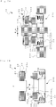
- Fig. 7A is a sectional diagram of a sealing device 1C according to the third embodiment of the present invention.
- the sealing device 1C is provided with a rotating shaft 11C which rotates centered on an axial center A, a rotating ring 23 which configures a rotating member 22 which is fixed to the rotating shaft 11C and rotates together with the rotating shaft 11C, and a fixed ring 32 which configures a fixing member 31C which rotates relative to the rotating shaft 11C.
- the fixed ring 32 is fitted to the inner circumference of a stepped inner diameter cylinder portion 33a of a case 33 which stores the fixed ring 32 and is fixed to the case 33.
- an outer circumference of an outer diameter cylinder portion 33b is fitted into a housing 41C to fix the case 33 to the housing 41C. Therefore, the fixed ring 32 is fixed to the housing 41C via the case 33.
- Fig. 7B is a sectional diagram distinctly illustrating each of the rotating member 22 and the fixing member 31C in which the sealing device 1C illustrated in Fig. 7A is removed from the housing 41C and the rotating shaft 11C is taken out.
- the rotating ring 23 which configures the rotating member 22 has a ring shape with a rectangular parallelopiped-shaped cross section, is formed from ceramics or the like, and is rigid.
- the rotating ring 23 is stored in a sleeve 25 having a letter U-shaped cross section via a cup gasket 24 having a letter L-shaped cross section.
- the sleeve 25 is fitted to the outer diameter portion of the rotating shaft 11C to be fixed to the rotating shaft 11C. Therefore, the rotating ring 23 includes a rotating ring-shaped end surface 23a which orthogonally intersects the axial center A of the rotating shaft 11C as the rotating surface and is fixed to the rotating shaft 11C.
- the fixed ring 32 which configures the fixing member 31C has a ring shape with a convex cross section, is formed from ceramics or the like, and is rigid.
- the fixed ring 32 includes a static annular surface 32a facing the rotating ring-shaped end surface 23a as a contacting target portion and the static annular surface 32a contacts and slides on the rotating ring-shaped end surface 23a.
- a metal spring 34 is held by a spring holder 35 between the fixed ring 32 and an inner circumferential base surface in a base portion 33c of the case 33.
- the spring holder 35 contacts the fixed ring 32 via an elastic rubber bellow 36.
- the metal spring 34 configures an elastic body which exhibits an elastic force for pushing the static annular surface 32a of the fixed ring 32 against the rotating ring-shaped end surface 23a of the rotating ring 23.
- the static annular surface 32a receives the biasing force in the axial direction of the rotating shaft 11C and contacts the rotating ring-shaped end surface 23a as the contacting target portion.
- the static annular surface 32a surrounds the outer circumference of the rotating shaft 11C to face the rotating ring-shaped end surface 23a and is provided in a non-rotating state due to the fixed ring 32 being supported by the housing 41C.
- the static annular surface 32a slides on the rotating ring-shaped end surface 23a due to the rotating shaft 11C rotating and rotates relative to the rotating ring-shaped end surface 23a.
- the sealing device 1C suppresses the leakage of a sealing target or the entrance of foreign matter via the shaft circumference of the rotating shaft 11C due to the static annular surface 32a being pushed against the rotating ring-shaped end surface 23a to contact and slide on the rotating ring-shaped end surface 23a.
- the sealing device 1C is used as a mechanical seal.
- the annular center of the static annular surface 32a in the fixed ring 32 is eccentric from the relative rotational center of the fixing member 31C.
- the relative rotational center B of the static annular surface 32a is disposed to be eccentric by an interval of the distance ⁇ with respect to the rotational center A of the rotating shaft 11C.
- torsion is generated by the friction force F and a restoring force which is centered on the relative rotational center B acts on the static annular surface 32a of the fixed ring 32 against the torsion.
- the static annular surface 32a of the fixed ring 32 receives a rotational drive force from the rotating ring-shaped end surface 23a of the rotating ring 23 in the rotational drive direction ⁇ which is intersected by the misalignment angle ⁇ , which is formed with the restoring direction ⁇ of the restoring force, in a predetermined angle range of 0 ⁇
- the sealing device 1C of the present embodiment due to the relative rotational center B of the static annular surface 32a of the fixed ring 32 being disposed to be eccentric with respect to the rotational center A of the rotating ring 23 and the rotational drive component Vsin ⁇ which orthogonally intersects the restoring direction ⁇ of the restoring force being applied to the static annular surface 32a of the fixed ring 32 from the rotating ring-shaped end surface 23a of the rotating ring 23, the restoring direction component Fcos ⁇ of the friction force F which acts on the static annular surface 32a of the fixed ring 32 and the restoring force which is exhibited by the housing 41C are autonomously stabilized to assume an equalized state, and the friction vibration is no longer generated by the friction which is generated between the rotating ring-shaped end surface 23a of the rotating ring 23 and the static annular surface 32a of the fixed ring 32. Therefore, the stick-slipping which occurs between the rotating ring-shaped end surface 23a and the static annular surface 32a is eliminated and a similar operational effect to that of
- the annular center of the static annular surface 32a in the fixed ring 32 is disposed to be eccentric from the relative rotational center of the fixing member 31C and the relative rotational center B of the static annular surface 32a is disposed to be eccentric with respect to the rotational center A of the rotating shaft 11C by an interval of the distance ⁇ .
- the relative rotational center B of the static annular surface 32a and the rotational center A of the rotating ring 23 may be eccentric by the distance ⁇ by causing the annular center of the static annular surface 32a to match the rotational center of the fixing member 31C as illustrated in Fig.
- FIG. 8A is a sectional diagram of the sealing device 1C' according to a modification example of the sealing device 1C according to the third embodiment
- Fig. 8B is a sectional diagram distinctly illustrating each of the rotating member 22 and the fixing member 31C in which the sealing device 1C' according to the modification example is removed from the housing 41C and the rotating shaft 11C is taken out.
- portions which are the same as or correspond to those in Fig. 7 will be given the same symbols and the description thereof will be omitted.
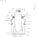
- Fig. 9A is a sectional diagram of the main parts of a sealing device 1D according to the fourth embodiment of the present invention, and a complete image is illustrated in Fig. 10 .
- the sealing device 1D suppresses the leakage of the sealing target from a ball joint portion or the entrance of foreign matter to the ball joint portion.
- the sealing device 1D is provided with a dust cover 51 illustrated in Fig. 9B .
- a ball joint is provided with a ball stud 52 which includes a spherical portion 52b on one end of a shaft portion 52a, a socket 53 which supports the ball stud 52 to rotate and rock freely, and a knuckle 54 which serves as an attaching target portion of the ball stud 52 which is fixed to the shaft portion 52a on the opposite side from the spherical portion 52b.
- the socket 53 is provided with an annular case 53a, a base plate 53b which is fixed to the base side of the case 53a, and a bearing 53c of the spherical portion 52b.
- the bearing 53c includes a bearing surface 53d which is configured by a spherical surface having the same radius of curvature as that of the spherical portion 52b.
- the knuckle 54 is fixed to the shaft portion 52a by a nut 55.
- the dust cover 51 includes a trunk portion 51a, a fixing target portion 51b, and a seal portion 51c.
- the trunk portion 51a which has deformable elasticity and is formed from a film which has a bowl shape.
- the fixing target portion 51b is provided on one end side of the trunk portion 51a and is fixed to the socket 53 which supports the ball stud 52 to rotate and rock freely.
- the seal portion 51c is provided on the other end side of the trunk portion 51a and is provided to slide freely with respect to each of the shaft portion 52a of the ball stud 52 and the knuckle 54. Accordingly, the ball stud 52 rocks with respect to the socket 53 in a direction indicated by an arrow S and rotates with respect to the socket 53 in a direction indicated by an arrow R.
- the fixing target portion 51b is a metal member which is configured by a toric plate-shaped portion 51b1, a first cylindrical portion 51b2 which is provided on the inner circumferential surface side of the plate-shaped portion 51b1, and a second cylindrical portion 51b3 which is provided on the outer circumferential surface side of the plate-shaped portion 51b1.
- the fixing target portion 51b is fixed to one end of the trunk portion 51a by the second cylindrical portion 51b3 being swaged in a state in which one end of the trunk portion 51a is fitted into the fixing target portion 51b.
- the fixing target portion 51b is fixed to the end portion of the case 53a of the socket 53 by fitting.
- the seal portion 51c is configured of a metal reinforcing ring 51d and a rubber-form elastic body seal main body 51e which is provided integrally with the reinforcing ring 51d.
- the reinforcing ring 51d is configured of a toric plate-shaped portion 51d1, a first cylindrical portion 51d2 which is provided on the inner circumferential surface side of the plate-shaped portion 51d1, and a second cylindrical portion 51d3 which is provided on the outer circumferential surface side of the plate-shaped portion 51d1.
- the reinforcing ring 51d is fixed to the other end of the trunk portion 51a by the second cylindrical portion 51d3 being swaged in a state in which the other end of the trunk portion 51a is fitted into the reinforcing ring 51d.
- the seal main body 51e is provided with an inner circumferential seal portion which is configured by a first annular convex portion 51e1, a second annular convex portion 51e2, and a third annular convex portion 51e3, and a dust seal portion which is configured by a dust lip 51e4.
- the ball stud 52 configures a rotating shaft which rotates centered on the axial center A of the shaft portion 52a.
- the knuckle 54 configures the rotating member which includes an attaching target surface 54a as a rotating surface.
- the elastic seal main body 51e configures a fixing member and is provided with the dust lip 51e4, which contacts the attaching target surface 54a, as a contacting target portion.
- the trunk portion 51a exhibits the elastic force of the trunk portion 51a as a biasing force to push the dust lip 51e4 against the attaching target surface 54a in the axial direction of the ball stud 52.
- the sealing device 1D suppresses the leakage of the sealing target from the ball joint portion or the entrance of foreign matter to the ball joint portion via the shaft portion 52a of the ball stud 52 in the seal portion 51c due to the dust lip 51e4 receiving the elastic force which is exhibited by the trunk portion 51a to be pushed against and contact the attaching target surface 54a and due to the dust lip 51e4 sliding on the attaching target surface 54a when the ball stud 52 rotates.
- the relative rotational center of the dust cover 51 matches the rotational center A of the knuckle 54
- the relative rotational center B of the dust lip 51e4 is eccentric from the rotational center A of the knuckle 54. Therefore, the relative rotational center B of the dust lip 51e4 is disposed to be eccentric with respect to the rotational center A of the knuckle 54 by an interval of the distance ⁇ .
- torsion is generated by the friction force F and a restoring force which is centered on the relative rotational center B acts on the dust lip 51e4 against the torsion.
- the dust lip 51e4 receives a rotational drive force from the attaching target surface 54a of the knuckle 54 in the rotational drive direction ⁇ which is intersected by the misalignment angle ⁇ , which is formed with the restoring direction ⁇ of the restoring force, in a predetermined angle range of 0 ⁇
- the sealing device 1D of the present embodiment due to the relative rotational center B of the dust lip 51e4 being disposed to be eccentric with respect to the rotational center A of the attaching target surface 54a and the rotational drive component Vsin ⁇ which orthogonally intersects the restoring direction ⁇ of the restoring force being applied to the dust lip 51e4 from the attaching target surface 54a of the knuckle 54, the restoring direction component Fcos ⁇ of the friction force F which acts on the dust lip 51e4 and the restoring force which is exhibited by the trunk portion 51a are autonomously stabilized to assume an equalized state, and the friction vibration is no longer generated by the friction which is generated between the attaching target surface 54a of the knuckle 54 and the dust lip 51e4. Therefore, the stick-slipping which occurs in the seal portion 51c of the dust cover 51 is eliminated and a similar operational effect to that of the sealing device 1A according to the first embodiment is achieved.
- the eccentricity distance ⁇ of the relative rotational center B to the rotational center A may be set to 10% to 40%, preferably to 20% to 30% of the diameter of the contacting target portions 31b1 and 31h3, the static annular surface 32a, and the dust lip 51e4 which rotate relatively.
- the sealing device according to the present invention for suppressing leakage of a sealing target or the entrance of foreign matter via a shaft circumference of various rotating shafts in delivery machinery, construction machinery, agricultural machinery, or the like.
Landscapes
- Engineering & Computer Science (AREA)
- General Engineering & Computer Science (AREA)
- Mechanical Engineering (AREA)
- Sealing With Elastic Sealing Lips (AREA)
Abstract
Description
- The present invention relates to a sealing device which suppresses leakage of a sealing target or the entrance of foreign matter via a shaft circumference of a rotating shaft due to a contacting target portion of a lip portion or the like being pushed against a rotating surface to contact and slide on the rotating surface.
- An oil seal which is disclosed in
Patent Literature 1 or the like is an example of this type of sealing device in the related art. The oil seal is a functional component which is used in many devices with the object of keeping a sealing fluid inside an apparatus and suppressing the entrance of foreign matter originating from outside of the apparatus into the apparatus. As indicated inPatent Literature 1, there is an oil seal having a structure that achieves sealing by pushing a contacting target portion of a non-rotating lip portion or the like, which is fixed to a housing and is static, against a rotating surface which is fixed to a rotating shaft and rotates together with the rotating shaft, so as to cause the contacting target portion to contact the rotating surface. - [PTL 1]
JP-A-2012-57729 - However, in the sealing device of the related art having the structure which is described above, frictional resistance is generated in sliding surfaces of the rotating surface and the contacting target portion which push against each other due to relative rotation between the two. There is a case in which a friction coefficient of the frictional resistance is reduced as the rotation frequency of the rotating shaft increases, stick-slipping occurs between the rotating surface and the contacting target portion in a region in which the frictional resistance is reduced, and as a result, seal squealing is generated. In order to suppress the squealing reduction, it is necessary to eliminate the stick-slipping.
- In order to eliminate the stick-slipping, there are measures which reduce the surface pressure by reducing a pushing load which pushes the contacting target portion against the rotating surface, reducing the lip rigidity of the contacting target portion, and the like. There are also measures which achieve an optimization of the sliding surface roughness, an optimization of the coating and rubber properties of a sliding member, and the like to modify the sliding member. However, modifying the pushing load or the constituent elements of the seal such as the members which are used often leads to a notable loss of balance with the other functions of the seal such as friction properties, product lifespan, and lubricant properties. Great time and cost are expended in order to assess this balance in the actual field of seal squealing countermeasures.
- The present invention is provided in order to solve the problem and is a sealing device including a rotating shaft which rotates centered on an axial center, a rotating member which includes a rotating surface, which projects in a direction which orthogonally intersects the axial center and surrounds an outer circumference of the rotating shaft, and rotates together with the rotating shaft, and a fixing member which includes a contacting target portion which is provided in a non-rotating state to surround an outer circumference of the rotating shaft and face the rotating surface, receives a biasing force in an axial direction of the rotating shaft to contact the rotating surface, slides on the rotating surface due to the rotating shaft rotating, and rotates relative to the rotating shaft, in which the sealing device suppresses leakage of a sealing target or entrance of foreign matter via a shaft circumference of the rotating shaft due to the contacting target portion being pushed against the rotating surface and contacting and sliding on the rotating surface, and in which in the fixing member, a relative rotational center of the contacting target portion is disposed to be eccentric with respect to a rotational center of the rotating shaft, the contacting target portion receives a rotational drive force from the rotating shaft in a direction which intersects, in a predetermined angle range, a restoring direction of a restoring force which is exhibited around the relative rotational center against torsion which is generated by a friction force which is generated between the contacting target portion and the rotating surface, and a rotational drive component which orthogonally intersects the restoring direction of the restoring force is applied to the contacting target portion from the rotating surface.
- According to the present configuration, due to the side-slipping drive component of a direction which orthogonally intersects the restoring direction of the restoring force being applied to the contacting target portion of the fixing member from the rotating surface of the rotating member, the restoring force and the restoring direction component of the friction force which acts on the contacting target portion are autonomously stabilized to assume an equalized state, friction vibration is no longer generated by the friction which is generated between the rotating surface and the contacting target portion, and the stick-slipping is eliminated. Therefore, merely by appropriately setting the relative positional relationship between the rotating surface of the rotating member and the contacting target portion of the fixing member without greatly modifying the constituent elements of the seal which costs a great amount of time and money, it is possible to perform seal squealing countermeasures at low cost using an extremely simple configuration. Therefore, even in a case in which the friction properties which arise in the sealed surface have a negative incline in relation to the sliding velocity and the frictional resistance decreases as the rotation frequency of the rotating shaft increases, it is possible to suppress the generation of unusual sounds which originate in the stick-slipping. In a case in which the lubricant such as a grease or an oil which is initially sealed into the sealing device is depleted when the sealing device is used in an actual marketplace, it is possible to suppress the generation of unusual sounds which originate in the stick-slipping.
- In the present invention, the rotating member is a slinger which includes a flange surface as the rotating surface and is fixed to the rotating shaft, the fixing member includes a lip portion, a distal end portion of which contacts and slides on the flange surface as the contacting target portion, which exhibits, as the biasing force, an elastic force for pushing the distal end portion against the flange surface, and a metal ring which supports the lip portion, and the sealing device is configured from an oil seal which suppresses leakage of a sealing target or entrance of foreign matter via a shaft circumference of the rotating shaft due to the distal end portion of the lip portion being pushed against the flange surface to contact and slide on the flange surface.
- According to the present configuration, a rotational drive component which orthogonally intersects the restoring direction of the restoring force is applied to the lip portion from the flange surface of the slinger due to the relative rotational center of the lip portion being disposed to be eccentric in relation to the rotational center of the slinger and the lip portion receiving a rotational drive force from the slinger in a direction which intersects a restoring direction of the restoring force in a predetermined angle range. Therefore, the restoring force and the restoring direction component of the friction force which acts on the lip portion are autonomously stabilized to assume an equalized state, friction vibration is no longer generated by the friction which is generated between the flange surface of the slinger and the lip portion, and the stick-slipping is eliminated from the oil seal.
- In the present invention, the rotating shaft includes a sealing portion which is axially sealed, the rotating member is a slinger which includes a flange surface as the rotating surface and is fixed to the rotating shaft in a vicinity of the sealing portion, the fixing member includes a lip portion which has a skirt-shape in which a diameter spreads from the sealing portion toward the flange surface, a distal end portion of the lip portion contacts and slides on the flange surface as the contacting target portion, and exhibits, as the biasing force, an elastic force for pushing the distal end portion against the flange surface, and the sealing device suppresses, together with the sealing portion, leakage of a sealing target or entrance of foreign matter via a shaft circumference of the rotating shaft due to the distal end portion of the lip portion being pushed against the flange surface to contact and slide on the flange surface.
- According to the present configuration, a rotational drive component which orthogonally intersects the restoring direction of the restoring force is applied to the lip portion from the flange surface of the slinger due to the relative rotational center of the lip portion which has a skirt shape being disposed to be eccentric in relation to the rotational center of the slinger and the lip portion receiving a rotational drive force from the slinger in a direction which intersects a restoring direction of the restoring force in a predetermined angle range. Therefore, the restoring force and the restoring direction component of the friction force which acts on the lip portion are autonomously stabilized to assume an equalized state, friction vibration is no longer generated by the friction which is generated between the flange surface of the slinger and the lip portion, and the stick-slipping which occurs in the skirt-shaped lip portion is eliminated.
- In the present invention, the rotating member includes a rotating ring which includes a rotating ring-shaped end surface which orthogonally intersects an axial center of the rotating shaft as the rotating surface, is fixed to the rotating shaft, and is rigid, the fixing member includes a static annular surface which faces the rotating ring-shaped end surface as the contacting target portion, includes a fixed ring in which the static annular surface contacts and slides on the rotating ring-shaped end surface, and is rigid, the sealing device further includes an elastic body which exhibits, as the biasing force, an elastic force for pushing the static annular surface of the fixed ring against the rotating ring-shaped end surface of the rotating ring, and the sealing device is configured from a mechanical seal which suppresses leakage of a sealing target or entrance of foreign matter via a shaft circumference of the rotating shaft due to the static annular surface of the fixed ring being pushed against the rotating ring-shaped end surface of the rotating ring to contact and slide on the rotating ring-shaped end surface.
- According to the present configuration, a rotational drive component which orthogonally intersects the restoring direction of the restoring force is applied to the static annular surface of the fixed ring from the rotating ring-shaped end surface of the rotating ring due to the relative rotational center of the static annular surface in the fixed ring being disposed to be eccentric in relation to the rotational center of the rotating ring and the static annular surface receiving a rotational drive force from the rotating ring in a direction which intersects a restoring direction of the restoring force in a predetermined angle range. Therefore, the restoring force and the restoring direction component of the friction force which acts on the static annular surface of the fixed ring are autonomously stabilized to assume an equalized state, friction vibration is no longer generated by the friction which is generated between the rotating ring-shaped end surface of the rotating ring and the static annular surface of the fixed ring, and the stick-slipping is eliminated from the mechanical seal.
- In the present invention, the sealing device further includes a dust cover which includes a trunk portion which has deformable elasticity, a fixing target portion which is provided to one end side of the trunk portion and is fixed to a socket which supports a ball stud to rotate and rock freely, and a seal portion which is provided on another end side of the trunk portion to slide freely with respect to each of a shaft portion of the ball stud having a spherical portion on one end and an attaching target portion of the ball stud, in which the rotating shaft is the ball stud, in which the rotating member is the attaching target portion which includes an attaching target surface as the rotating surface and is fixed to a shaft portion of the ball stud, in which the fixing member is an elastic seal main body which is provided with a dust lip which contacts the attaching target surface as the contacting target portion and is provided on the seal portion, and in which the sealing device suppresses leakage of a sealing target from a ball joint portion or entrance of foreign matter to the ball joint portion via a shaft circumference of the ball stud due to the dust lip receiving an elastic force which is exhibited by the trunk portion as the biasing force, being pushed against the attaching target surface to contact the attaching target surface, and the dust lip sliding on the attaching target surface when the ball stud rotates.
- According to the present configuration, a rotational drive component which orthogonally intersects the restoring direction of the restoring force is applied to the dust lip from the attaching target surface of the attaching target portion due to the relative rotational center of the dust lip being disposed to be eccentric in relation to the rotational center of the attaching target portion and the dust lip receiving a rotational drive force from the attaching target portion in a direction which intersects a restoring direction of the restoring force in a predetermined angle range. Therefore, the restoring force and the restoring direction component of the friction force which acts on the dust lip are autonomously stabilized to assume an equalized state, friction vibration is no longer generated by the friction which is generated between the attaching target surface of the attaching target portion and the dust lip, and the stick-slipping which occurs in the seal portion of the dust cover is eliminated.
- In the present invention, the predetermined angle range is a range indicated by an
inequality expression 0 < |φ| ≤ 90° when an absolute value of an angle φ which is formed by a rotational drive direction of the rotating shaft with a restoring direction of the restoring force is set to |φ|. - According to the present configuration, the rotational drive component which orthogonally intersects the restoring direction of the restoring force becomes non-zero and is applied to the contacting target portion of the fixing member from the rotating surface of the rotating member, and the attenuation manifests in the friction vibration originating in the side-slipping drive component. Therefore, the friction vibration which is generated by the friction which is generated between the rotating surface of the rotating member and the contacting target portion of the fixing member is suppressed and the stick-slipping is eliminated.
- According to the present invention, merely by appropriately setting the relative positional relationship between the rotating surface of the rotating member and the contacting target portion of the fixing member without greatly modifying the constituent elements of the seal which costs a great amount of time and money, it is possible to perform seal squealing countermeasures at low cost using an extremely simple configuration.
-
-
Fig. 1 is a sectional diagram of a sealing device according to a first embodiment of the present invention. -
Fig. 2 is a sectional diagram distinctly illustrating each of a slinger and a fixing member which configure the sealing device according to the first embodiment depicted inFig. 1 . -
Fig. 3 is a diagram representing the relationship between a rotation drive velocity V which is received by a random point P of a contacting target portion, a restoring velocity v of a restoring force which acts on the contacting target portion, and a friction force F which is generated on the contacting target portion in the sealing device according to the first embodiment of the present invention. -
Figs. 4A and 4B are a plan view and a side view for explaining a principle of the sealing device of the present invention. -
Fig. 5 is a sectional diagram of a sealing device according to a second embodiment of the present invention. -
Fig. 6 is a sectional diagram distinctly illustrating each of a slinger and a fixing member which configure the sealing device according to the second embodiment depicted inFig. 5 . -
Fig. 7A is a sectional diagram of a sealing device according to a third embodiment of the present invention andFig. 7B is a sectional diagram distinctly illustrating each of a rotating member and a fixing member which configure the sealing device according to the third embodiment depicted inFig. 7A . -
Fig. 8A is a sectional diagram of a sealing device according to a modification example of the third embodiment of the present invention andFig. 8B is a sectional diagram distinctly illustrating each of a rotating member and a fixing member which configure the sealing device according to the modification of the third embodiment depicted inFig. 8A . -
Fig. 9A is a sectional diagram of the main parts of a sealing device according to a fourth embodiment of the present invention andFig. 9B is a sectional diagram of a dust cover which configures the sealing device according to the fourth embodiment depicted inFig. 9A . -
Fig. 10 is a sectional diagram illustrating a complete image of the sealing device according to the fourth embodiment, the main parts of which are illustrated inFig. 9A . - Next, a description will be given of embodiments of a sealing device according to the present invention.
-
Fig. 1 is a sectional diagram of a sealing device 1A according to the first embodiment of the present invention. The sealing device 1A is configured to include a rotating shaft 11A which rotates centered on an axial center A, a slinger 21A which is a rotating member which is fixed to the rotating shaft 11A and rotates together with the rotating shaft 11A, and a fixing member 31A which rotates relative to the rotating shaft 11A. An outer circumference of the fixing member 31A is fitted into a housing 41A to fix the fixing member 31A to the housing 41A. -
Fig. 2 is a sectional diagram distinctly illustrating each of the slinger 21A and the fixing member 31A in which the sealing device 1A illustrated inFig. 1 is removed from the housing 41A and the rotating shaft 11A is taken out. - The slinger 21A is produced by punching and press-forming a metal plate and includes a cylinder portion 21a which is pressure fitted to the outer circumferential surface of the rotating shaft 11A and a flange portion 21b which extends in a disc shape in an outward radial direction from the cylinder portion 21a. The flange portion 21b includes, as a rotating surface, a flange surface 21b1 which projects in a direction orthogonally intersecting the axial center A of the rotating shaft 11A to surround the outer circumference of the rotating shaft 11A.
- The fixing member 31A is obtained by integrally molding a rubber elastic material as a lip portion on a metal ring 31a which is produced by punching and press-forming a metal plate. Two grease lip portions 31b, the distal end portions of which contact the flange surface 21b1, and a dust lip portion 31c, the distal end portion of which contacts the outer circumference of the cylinder portion 21a, are formed in the lip portion. The lip portion is supported by the metal ring 31a. The grease lip portions 31b exhibit an elastic force for pushing the distal end portions of the grease lip portions 31b against the flange surface 21b1, and the distal end portions receive a biasing force in an axial direction of the rotating shaft 11A to flex as illustrated in
Fig. 1 . - In the fixing member 31A, the distal end portions of the grease lip portions 31b receive the biasing force in the axial direction of the rotating shaft 11A and contact the flange surface 21b1 as contacting target portions 31b1. The contacting target portions 31b1 surround the outer circumference of the rotating shaft 11A to face the flange surface 21b1 and are provided in a non-rotating state due to the fixing member 31A being supported by the housing 41A. The contacting target portions 31b1 slide on the flange surface 21b1 due to the rotating shaft 11A rotating and the contacting target portions 31b1 rotate relative to the flange surface 21b1. The sealing device 1A suppresses the leakage of a sealing target or the entrance of foreign matter via the shaft circumference of the rotating shaft 11A due to the distal end portions of the grease lip portions 31b being pushed against the flange surface 21b1 to contact and slide on the flange surface 21b1. The sealing device 1A is used as a hub bearing seal or an oil seal, for example.
- In the present embodiment, although the relative rotational center of the fixing member 31A matches the rotational center A of the rotating shaft 11A, the annular shape of the grease lip portions 31b is not symmetrical to the relative rotational center of the fixing member 31A and is formed asymmetrically. Therefore, a relative rotational center B of the contacting target portions 31b1 of the grease lip portions 31b is disposed to be eccentric by an interval of a distance ε with respect to the rotational center A of the rotating shaft 11A. When the rotating shaft 11A rotates and the slinger 21A rotates together with the rotating shaft 11A, the friction force F is generated between the contacting target portions 31b1 of the grease lip portions 31b and the flange surface 21b1. In the housing 41A which supports the fixing member 31A, torsion is generated by the friction force F and a restoring force which is centered on the relative rotational center B acts on the contacting target portions 31b1 against the torsion. The contacting target portions 31b1 receive a rotational drive force from the flange surface 21b1 of the slinger 21A in a direction which intersects the restoring direction of the restoring force in a predetermined angle range and a rotational drive component which orthogonally intersects the restoring direction of the restoring force is applied to the contacting target portions 31b1 from the flange surface 21b1.
- In other words, as illustrated in
Fig. 3 , when the contacting target portions 31b1 which slides on the flange surface 21b1 centered on the relative rotational center B is depicted by a circle with a dot and the flange surface 21b1 which rotates centered on the rotational center A is depicted by a white circle, the friction force F between the contacting target portions 31b1 and the flange surface 21b1 acts on a random point P on the contacting target portions 31b1 of the grease lip portions 31b. A rotational drive force of a rotation drive velocity V from the flange surface 21b1 acts in a rotational drive direction β. The restoring force of the restoring velocity v acts in a restoring direction α. At this time, since the relative rotational center B of the contacting target portions 31b1 is eccentric from the rotational center A of the flange surface 21b1 by the distance ε, the rotational drive direction β of the rotational drive force which the contacting target portions 31b1 receive from the flange surface 21b1 intersects the restoring direction α of the restoring force at a predetermined angle φ, and a rotational drive component Vsinφ which orthogonally intersects the restoring direction α of the restoring force is applied to the contacting target portions 31b1. - In the present embodiment, the absolute value |φ| of the angle φ (the misalignment angle) which is formed by the rotational drive direction β with the restoring direction α of the restoring force is set in a predetermined angle range indicated by
inequality expression 0 < |φ| ≤ 90° and the drive component Vsinφ is set to a nonzero value. According to this setting, the rotational drive component Vsin φ which causes side-slipping in relation to the restoring direction α of the restoring force is secured. - According to the sealing device 1A of the present embodiment, due to the rotational drive component Vsin φ which orthogonally intersects the restoring direction α of the restoring force being applied to the contacting target portions 31b1 of the grease lip portions 31b from the flange surface 21b1 of the slinger 21A, a restoring direction component Fcosθ of the friction force F which acts on the contacting target portions 31b1 of the grease lip portions 31b and the restoring force which is exhibited by the housing 41A are autonomously stabilized to assume an equalized state, and friction vibration is no longer generated by the friction which is generated between the flange surface 21b1 of the slinger 21A and the contacting target portions 31b1 of the grease lip portions 31b.
- Here, θ is an angle formed by a relative velocity Vrel with respect to the restoring direction α of the restoring force, the relative velocity Vrel being between the rotation drive velocity V of the flange surface 21b1 and the restoring velocity v of the restoring force which is applied to the contacting target portions 31b1 of the grease lip portions 31b from the housing 41A. The restoring velocity v of the restoring force is represented by a first-order differentiation x' of a displacement amount x by which the contacting target portions 31b1 are displaced in a circumferential direction corresponding to the torsion. Since the friction force F which acts on the contacting target portions 31b1 of the grease lip portions 31b acts in a direction which reduces the relative velocity Vrel, the angle which the friction force F forms with respect to the restoring direction α of the restoring force is also θ.
- In other words, due to the relative rotational center B of the toric contacting target portions 31b1 being disposed to be eccentric with respect to the rotational center A of the flange surface 21b1 of the slinger 21A and the rotational drive direction β of the flange surface 21b1 intersecting the restoring direction α of the restoring force in a predetermined angle range, the rotational drive component Vsinφ which orthogonally intersects the restoring direction α of the restoring force is applied to the toric contacting target portions 31b1 from the flange surface 21b1. In the present embodiment, since the misalignment angle φ which is formed between the rotational drive direction β and the restoring direction α is set in a range of 0 < |φ| ≤ 90°, the rotational drive component Vsinφ which orthogonally intersects the restoring direction α of the restoring force becomes non-zero and is applied to the contacting target portions 31b1, and attenuation which originates in the rotational drive component Vsinφ which causes the side-slipping manifests in the friction vibration. Therefore, the restoring direction component Fcosθ of the friction force F which acts on the contacting target portions 31b1 of the grease lip portions 31b and the restoring force which is exhibited by the housing 41A are autonomously stabilized to assume an equalized state, and the friction vibration is no longer generated by the friction which is generated between the flange surface 21b1 of the slinger 21A and the contacting target portions 31b1 of the grease lip portions 31b.
- Accordingly, the stick-slipping which occurs between the flange surface 21b1 and the contacting target portions 31b1 is eliminated from the oil seal. Therefore, merely by appropriately setting the relative positional relationship between the flange surface 21b1 of the slinger 21A and the contacting target portions 31b1 of the grease lip portions 31b without greatly modifying the constituent elements of the seal which costs a great amount of time and money, it is possible to perform seal squealing countermeasures at low cost using an extremely simple configuration. Therefore, even in a case in which the friction properties which arise in the flange surface 21b1 have a negative incline in relation to the sliding velocity and the frictional resistance decreases as the rotation frequency of the rotating shaft 11A increases, it is possible to suppress the generation of unusual sounds which originate in the stick-slipping. In a case in which the lubricant such as a grease or an oil which is initially sealed into the sealing device 1A is depleted when the sealing device 1A is used in an actual marketplace, it is possible to suppress the generation of unusual sounds which originate in the stick-slipping.
-
Figs. 4A and 4B are a plan view and a side view for explaining the sealing principle of the sealing device 1A of the present embodiment.Figs. 4A and 4B schematically represent the slipping friction between asphere 5 and aplate 6. It is possible to apply the principle described hereinafter to the sealing principle of the sealing device 1A of the present embodiment by adapting thesphere 5 to the grease lip portions 31b of the present embodiment and adapting theplate 6 to the flange surface 21b1. - The
sphere 5 having a mass m is attached to a right end of aspring 8 having a rigidity k which is fixed to astatic wall 7 by a left end of thespring 8. The motion of thesphere 5 is only allowed as translation in a bending direction (an x-direction) of thespring 8. Theplate 6 contacts thesphere 5 with a perpendicular load W and moves linearly at the drive velocity V to form a misalignment angle φ with the x-direction. Using the position of thesphere 5 when thespring 8 is at the natural length of thespring 8 as anorigin 0, when the position of thesphere 5 at a time t is set to x(t), the motion velocity of thesphere 5 may be represented as x' using a differentiation (') which is related to t. When the relative velocity Vrel between the drive velocity V of theplate 6 and the motion velocity x' of thesphere 5 is set to θ, since the friction force F which acts on thesphere 5 acts in a direction which reduces the relative velocity Vrel, the angle which the friction force F forms with the x-direction also becomes θ. When the misalignmentangle φ ≠ 0, the relative velocity Vrel has a non-zero lateral sliding component Vsin φ and the orientation of the friction force F changes according to the change in the motion velocity x'. - When the magnitude of the friction force which acts on the
sphere 5 is represented by the function F = F(Vrel) of the relative velocity Vrel, the motion equation of thesphere 5 is given by the following Equation (1).
- Here, the relative velocity Vrel and the angle θ are geometrically defined by Equations (2) and (3).


- When the misalignment
angle φ ≠ 0, since the friction force which acts on thesphere 5 is limited to the dynamic friction force, F(Vrel) is given by the following Equation (4) using the dynamic friction coefficient µ(Vrel).
- When the x component Fcosθ of the friction force F which acts on the
sphere 5 and the restoring force kx of thespring 8 are balanced, an equilibrium point xeq is given by the following Equation (5) from the function Vrel = V, θ = φ which may be obtained in consideration of x' = 0.
- A disturbance x∼ from the equilibrium point xeq is provided using the following Equation (6) in order to consider the stability of the equilibrium point xeq.


- Here, coefficients c1 and c2 of (x∼)' of the second term on the left are the following Equations (8) and (9).


- The term µ'(V) of Equation (8) means the slope of the function µ = µ(Vrel) in Vrel = V. The coefficient c1 represents a viscosity attenuation which is exhibited according to a relative velocity dependence of the friction coefficient, and the coefficient c2 represents the viscosity attenuation which is exhibited by providing the non-zero misalignment angle φ (the lateral sliding component Vsinφ).
- Since Equation (7) is a second-order linear ordinary differential equation, the stability of the equilibrium point xeq is determined by the sign of the coefficients of (x∼)'. In other words, when the following Expression (10)

- When µ' (V) > 0 is true, Expression (11) is true for a random φ, and when µ' (V) < 0 is true, c1 < 0 (negative attenuation) renders the equilibrium point xeq unstable. However, when the misalignment angle φ which satisfies the following Equation (12) is given, the effect of c2 > 0 (positive attenuation) exceeds the effect of c1 < 0 and the equilibrium point xeq becomes stable.

-
Fig. 5 is a sectional diagram of a sealing device 1B according to the second embodiment of the present invention. The sealing device 1B is configured to include a rotating shaft 11B which rotates centered on the axial center A, a slinger 21B which is a rotating member which is fixed to the rotating shaft 11B and rotates together with the rotating shaft 11B, and a fixing member 31B which rotates relative to the rotating shaft 11B. The rotating shaft 11B is formed from a large diameter portion 11a which has a large diameter and a small diameter portion 11b which has a smaller diameter than the diameter of the large diameter portion 11a, and the rotating shaft 11B includes a sealing portion 11c which is axially sealed by an oil seal on an end portion of the large diameter portion 11a. In the fixing member 31B, an outer circumference of the sealing portion 11c is fitted into a housing 41B to fix the fixing member 31B to the housing 41B. -
Fig. 6 is a sectional diagram distinctly illustrating each of the slinger 21B and the fixing member 31B in which the sealing device 1B illustrated inFig. 5 is removed from the housing 41B and the rotating shaft 11B is taken out. - The slinger 21B is produced by punching and press-forming a metal plate and includes an inner diameter cylinder portion 21d which is pressure fitted to the outer circumferential surface of the rotating shaft 11B, a flange portion 21e which extends in a disc shape in an outward radial direction from the inner diameter cylinder portion 21d, and an outer diameter cylinder portion 21f which rises from the outer circumferential edge portion of the flange portion 21e parallel to the inner diameter cylinder portion 21d. The slinger 21B is fixed to the small diameter portion 11b of the rotating shaft 11B in the vicinity of the sealing portion 11c. The flange portion 21e includes, as a rotating surface, a flange surface 21e1 which projects in a direction orthogonally intersecting the axial center A of the rotating shaft 11B to surround the outer circumference of the rotating shaft 11B.
- The oil seal which forms the sealing portion 11c of the fixing member 31B is obtained by integrally molding a rubber elastic material as a lip portion on a metal ring 31e which is produced by punching and press-forming a metal plate. A shaft lip portion 31f and a shaft dust lip portion 31g, the distal end portions of which contact the large diameter portion 11a of the rotating shaft 11B, and an end surface lip portion 31h, the distal end portion of which contacts the flange surface 21e1, are formed in the lip portion. The lip portion is supported by the metal ring 31e. A
metal spring 34 is provided to cover the outer circumference of the shaft lip portion 31f and the shaft lip portion 31f is pushed against the outer circumference of the large diameter portion 11a by themetal spring 34. - The end surface lip portion 31h includes a tubular portion 31h1 which surrounds the outer circumferential edge portion of the end portion of the large diameter portion 11a, and a skirt portion 31h2, the diameter of which spreads from the tubular portion 31h1 toward the flange surface 21e1. The end surface lip portion 31h exhibits an elastic force for pushing the distal end portions of the end surface lip portion 31h against the flange surface 21e1, and the distal end portion receives a biasing force in an axial direction of the rotating shaft 11B to flex as illustrated in
Fig. 5 . - In the fixing member 31B, the distal end portion of the end surface lip portion 31h receives the biasing force in the axial direction of the rotating shaft 11B and contacts the flange surface 21e1 as a contacting target portion 31h3. The contacting target portion 31h3 surrounds the outer circumference of the rotating shaft 11B to face the flange surface 21e1 and is provided in a non-rotating state due to the fixing member 31B being supported by the housing 41B. The contacting target portion 31h3 slides on the flange surface 21e1 due to the rotating shaft 11B rotating and the contacting target portion 31h3 rotates relative to the flange surface 21e1. Together with the sealing portion 11c, the sealing device 1B suppresses the leakage of a sealing target or the entrance of foreign matter via the shaft circumference of the rotating shaft 11B due to the contacting target portion 31h3 of the end surface lip portion 31h being pushed against the flange surface 21e1 to contact and slide on the flange surface 21e1. The sealing device 1B is used as a drive unit seal which is used in an output shaft of a differential gear, for example.
- In the present embodiment, although the relative rotational center of the fixing member 31B matches the rotational center A of the rotating shaft 11B, the annular shape of the skirt portion 31h2 of the end surface lip portion 31h is not symmetrical to the relative rotational center of the fixing member 31B and is formed asymmetrically. Therefore, a relative rotational center B of the contacting target portions 31h3 in the end surface lip portion 31h is disposed to be eccentric by an interval of the distance ε with respect to the rotational center A of the rotating shaft 11B. When the rotating shaft 11B rotates and the slinger 21B rotates together with the rotating shaft 11B, the friction force F is generated between the contacting target portions 31h3 of the grease lip portions 31h and the flange surface 21e1. In the housing 41B which supports the fixing member 31B, torsion is generated by the friction force F and a restoring force which is centered on the relative rotational center B acts on the contacting target portion 31h3 against the torsion. The contacting target portion 31h3 receives a rotational drive force from the flange surface 21e1 of the slinger 21B in the rotational drive direction β which is intersected by the misalignment angle φ, which is formed with the restoring direction α of the restoring force, in a predetermined angle range of 0 < |φ| ≤ 90° and a rotational drive component Vsinφ which orthogonally intersects the restoring direction α of the restoring force is applied to the contacting target portion 31h3 from the flange surface 21e1.
- According to the sealing device 1B of the present embodiment, due to the relative rotational center B of the contacting target portion 31h3 in the skirt-shaped end surface lip portion 31h being disposed to be eccentric with respect to the rotational center A of the slinger 21B and the rotational drive component Vsinφ which orthogonally intersects the restoring direction α of the restoring force being applied to the contacting target portion 31h3 of the end surface lip portion 31h from the flange surface 21e1 of the slinger 21B, the restoring direction component Fcosθ of the friction force F which acts on the contacting target portion 31h3 of the end surface lip portion 31h and the restoring force which is exhibited by the housing 41B are autonomously stabilized to assume an equalized state, and the friction vibration is no longer generated by the friction which is generated between the flange surface 21e1 of the slinger 21B and the contacting target portion 31h3 of the end surface lip portion 31h. Therefore, the stick-slipping which occurs in the skirt-shaped end surface lip portion 31h is eliminated and a similar operational effect to that of the sealing device 1A according to the first embodiment is achieved.
-
Fig. 7A is a sectional diagram of a sealing device 1C according to the third embodiment of the present invention. The sealing device 1C is provided with a rotating shaft 11C which rotates centered on an axial center A, a rotatingring 23 which configures a rotatingmember 22 which is fixed to the rotating shaft 11C and rotates together with the rotating shaft 11C, and a fixedring 32 which configures a fixing member 31C which rotates relative to the rotating shaft 11C. The fixedring 32 is fitted to the inner circumference of a stepped inner diameter cylinder portion 33a of acase 33 which stores the fixedring 32 and is fixed to thecase 33. In thecase 33, an outer circumference of an outer diameter cylinder portion 33b is fitted into a housing 41C to fix thecase 33 to the housing 41C. Therefore, the fixedring 32 is fixed to the housing 41C via thecase 33. -
Fig. 7B is a sectional diagram distinctly illustrating each of the rotatingmember 22 and the fixing member 31C in which the sealing device 1C illustrated inFig. 7A is removed from the housing 41C and the rotating shaft 11C is taken out. - The rotating
ring 23 which configures the rotatingmember 22 has a ring shape with a rectangular parallelopiped-shaped cross section, is formed from ceramics or the like, and is rigid. The rotatingring 23 is stored in asleeve 25 having a letter U-shaped cross section via acup gasket 24 having a letter L-shaped cross section. Thesleeve 25 is fitted to the outer diameter portion of the rotating shaft 11C to be fixed to the rotating shaft 11C. Therefore, the rotatingring 23 includes a rotating ring-shaped end surface 23a which orthogonally intersects the axial center A of the rotating shaft 11C as the rotating surface and is fixed to the rotating shaft 11C. - The fixed
ring 32 which configures the fixing member 31C has a ring shape with a convex cross section, is formed from ceramics or the like, and is rigid. The fixedring 32 includes a static annular surface 32a facing the rotating ring-shaped end surface 23a as a contacting target portion and the static annular surface 32a contacts and slides on the rotating ring-shaped end surface 23a. Ametal spring 34 is held by aspring holder 35 between the fixedring 32 and an inner circumferential base surface in a base portion 33c of thecase 33. Thespring holder 35 contacts the fixedring 32 via anelastic rubber bellow 36. Themetal spring 34 configures an elastic body which exhibits an elastic force for pushing the static annular surface 32a of the fixedring 32 against the rotating ring-shaped end surface 23a of therotating ring 23. - In the fixed
ring 32, the static annular surface 32a receives the biasing force in the axial direction of the rotating shaft 11C and contacts the rotating ring-shaped end surface 23a as the contacting target portion. The static annular surface 32a surrounds the outer circumference of the rotating shaft 11C to face the rotating ring-shaped end surface 23a and is provided in a non-rotating state due to the fixedring 32 being supported by the housing 41C. The static annular surface 32a slides on the rotating ring-shaped end surface 23a due to the rotating shaft 11C rotating and rotates relative to the rotating ring-shaped end surface 23a. The sealing device 1C suppresses the leakage of a sealing target or the entrance of foreign matter via the shaft circumference of the rotating shaft 11C due to the static annular surface 32a being pushed against the rotating ring-shaped end surface 23a to contact and slide on the rotating ring-shaped end surface 23a. The sealing device 1C is used as a mechanical seal. - In the present embodiment, although the relative rotational center of the fixing member 31C matches the rotational center A of the rotating shaft 11C, the annular center of the static annular surface 32a in the fixed
ring 32 is eccentric from the relative rotational center of the fixing member 31C. In other words, the relative rotational center B of the static annular surface 32a is disposed to be eccentric by an interval of the distance ε with respect to the rotational center A of the rotating shaft 11C. When the rotating shaft 11C rotates and therotating ring 23 rotates together with the rotating shaft 11C, the friction force F is generated between the static annular surface 32a and the rotating ring-shaped end surface 23a. In the housing 41C which supports the fixing member 31C, torsion is generated by the friction force F and a restoring force which is centered on the relative rotational center B acts on the static annular surface 32a of the fixedring 32 against the torsion. The static annular surface 32a of the fixedring 32 receives a rotational drive force from the rotating ring-shaped end surface 23a of therotating ring 23 in the rotational drive direction β which is intersected by the misalignment angle φ, which is formed with the restoring direction α of the restoring force, in a predetermined angle range of 0 < |φ | ≤ 90° and a rotational drive component Vsinφ which orthogonally intersects the restoring direction α of the restoring force is applied to the static annular surface 32a from the rotating ring-shaped end surface 23a. - According to the sealing device 1C of the present embodiment, due to the relative rotational center B of the static annular surface 32a of the fixed
ring 32 being disposed to be eccentric with respect to the rotational center A of therotating ring 23 and the rotational drive component Vsin φ which orthogonally intersects the restoring direction α of the restoring force being applied to the static annular surface 32a of the fixedring 32 from the rotating ring-shaped end surface 23a of therotating ring 23, the restoring direction component Fcosθ of the friction force F which acts on the static annular surface 32a of the fixedring 32 and the restoring force which is exhibited by the housing 41C are autonomously stabilized to assume an equalized state, and the friction vibration is no longer generated by the friction which is generated between the rotating ring-shaped end surface 23a of therotating ring 23 and the static annular surface 32a of the fixedring 32. Therefore, the stick-slipping which occurs between the rotating ring-shaped end surface 23a and the static annular surface 32a is eliminated and a similar operational effect to that of the sealing device 1A according to the first embodiment is achieved. - In the third embodiment, a description is given of a case in which the annular center of the static annular surface 32a in the fixed
ring 32 is disposed to be eccentric from the relative rotational center of the fixing member 31C and the relative rotational center B of the static annular surface 32a is disposed to be eccentric with respect to the rotational center A of the rotating shaft 11C by an interval of the distance ε. However, the relative rotational center B of the static annular surface 32a and the rotational center A of therotating ring 23 may be eccentric by the distance ε by causing the annular center of the static annular surface 32a to match the rotational center of the fixing member 31C as illustrated inFig. 8B and causing the inner diameter center of the housing 41C to be eccentric from the rotational center A of the rotating shaft 11C as illustrated inFig. 8A without causing the annular center of the static annular surface 32a to be eccentric from the relative rotational center of the fixing member 31C.Fig. 8A is a sectional diagram of the sealing device 1C' according to a modification example of the sealing device 1C according to the third embodiment andFig. 8B is a sectional diagram distinctly illustrating each of the rotatingmember 22 and the fixing member 31C in which the sealing device 1C' according to the modification example is removed from the housing 41C and the rotating shaft 11C is taken out. InFig. 8 , portions which are the same as or correspond to those inFig. 7 will be given the same symbols and the description thereof will be omitted. - Even in the sealing device 1C' according to the modification example, due to the rotational drive component Vsin φ which orthogonally intersects the restoring direction α of the restoring force being applied to the static annular surface 32a of the fixed
ring 32 from the rotating ring-shaped end surface 23a of therotating ring 23, the restoring direction component Fcosθ of the friction force F which acts on the static annular surface 32a of the fixedring 32 and the restoring force which is exhibited by the housing 41C are autonomously stabilized to assume an equalized state, and the stick-slipping which occurs between the rotating ring-shaped end surface 23a and the static annular surface 32a is eliminated and a similar operational effect to that of the sealing device 1C according to the third embodiment is achieved. -
Fig. 9A is a sectional diagram of the main parts of a sealing device 1D according to the fourth embodiment of the present invention, and a complete image is illustrated inFig. 10 . - The sealing device 1D suppresses the leakage of the sealing target from a ball joint portion or the entrance of foreign matter to the ball joint portion. The sealing device 1D is provided with a
dust cover 51 illustrated inFig. 9B . - As illustrated in
Fig. 10 , a ball joint is provided with aball stud 52 which includes a spherical portion 52b on one end of a shaft portion 52a, a socket 53 which supports theball stud 52 to rotate and rock freely, and aknuckle 54 which serves as an attaching target portion of theball stud 52 which is fixed to the shaft portion 52a on the opposite side from the spherical portion 52b. The socket 53 is provided with an annular case 53a, a base plate 53b which is fixed to the base side of the case 53a, and a bearing 53c of the spherical portion 52b. The bearing 53c includes a bearing surface 53d which is configured by a spherical surface having the same radius of curvature as that of the spherical portion 52b. Theknuckle 54 is fixed to the shaft portion 52a by anut 55. - The
dust cover 51 includes a trunk portion 51a, a fixing target portion 51b, and a seal portion 51c. The trunk portion 51a which has deformable elasticity and is formed from a film which has a bowl shape. The fixing target portion 51b is provided on one end side of the trunk portion 51a and is fixed to the socket 53 which supports theball stud 52 to rotate and rock freely. The seal portion 51c is provided on the other end side of the trunk portion 51a and is provided to slide freely with respect to each of the shaft portion 52a of theball stud 52 and theknuckle 54. Accordingly, theball stud 52 rocks with respect to the socket 53 in a direction indicated by an arrow S and rotates with respect to the socket 53 in a direction indicated by an arrow R. - As illustrated in
Fig. 9B , the fixing target portion 51b is a metal member which is configured by a toric plate-shaped portion 51b1, a first cylindrical portion 51b2 which is provided on the inner circumferential surface side of the plate-shaped portion 51b1, and a second cylindrical portion 51b3 which is provided on the outer circumferential surface side of the plate-shaped portion 51b1. The fixing target portion 51b is fixed to one end of the trunk portion 51a by the second cylindrical portion 51b3 being swaged in a state in which one end of the trunk portion 51a is fitted into the fixing target portion 51b. As illustrated inFig. 10 , the fixing target portion 51b is fixed to the end portion of the case 53a of the socket 53 by fitting. - The seal portion 51c is configured of a metal reinforcing ring 51d and a rubber-form elastic body seal main body 51e which is provided integrally with the reinforcing ring 51d. The reinforcing ring 51d is configured of a toric plate-shaped portion 51d1, a first cylindrical portion 51d2 which is provided on the inner circumferential surface side of the plate-shaped portion 51d1, and a second cylindrical portion 51d3 which is provided on the outer circumferential surface side of the plate-shaped portion 51d1. The reinforcing ring 51d is fixed to the other end of the trunk portion 51a by the second cylindrical portion 51d3 being swaged in a state in which the other end of the trunk portion 51a is fitted into the reinforcing ring 51d. The seal main body 51e is provided with an inner circumferential seal portion which is configured by a first annular convex portion 51e1, a second annular convex portion 51e2, and a third annular convex portion 51e3, and a dust seal portion which is configured by a dust lip 51e4.
- The
ball stud 52 configures a rotating shaft which rotates centered on the axial center A of the shaft portion 52a. Theknuckle 54 configures the rotating member which includes an attaching target surface 54a as a rotating surface. The elastic seal main body 51e configures a fixing member and is provided with the dust lip 51e4, which contacts the attaching target surface 54a, as a contacting target portion. The trunk portion 51a exhibits the elastic force of the trunk portion 51a as a biasing force to push the dust lip 51e4 against the attaching target surface 54a in the axial direction of theball stud 52. The sealing device 1D suppresses the leakage of the sealing target from the ball joint portion or the entrance of foreign matter to the ball joint portion via the shaft portion 52a of theball stud 52 in the seal portion 51c due to the dust lip 51e4 receiving the elastic force which is exhibited by the trunk portion 51a to be pushed against and contact the attaching target surface 54a and due to the dust lip 51e4 sliding on the attaching target surface 54a when theball stud 52 rotates. - In the present embodiment, although the relative rotational center of the
dust cover 51 matches the rotational center A of theknuckle 54, the relative rotational center B of the dust lip 51e4 is eccentric from the rotational center A of theknuckle 54. Therefore, the relative rotational center B of the dust lip 51e4 is disposed to be eccentric with respect to the rotational center A of theknuckle 54 by an interval of the distance ε. When theball stud 52 rotates and theknuckle 54 rotates together with theball stud 52, the friction force F is generated between the dust lip 51e4 and the attaching target surface 54a of theknuckle 54. In the trunk portion 51a which supports the dust lip 51e4, torsion is generated by the friction force F and a restoring force which is centered on the relative rotational center B acts on the dust lip 51e4 against the torsion. The dust lip 51e4 receives a rotational drive force from the attaching target surface 54a of theknuckle 54 in the rotational drive direction β which is intersected by the misalignment angle φ, which is formed with the restoring direction α of the restoring force, in a predetermined angle range of 0 < |φ| ≤ 90° and a rotational drive component Vsin φ which orthogonally intersects the restoring direction α of the restoring force is applied to the dust lip 51e4 from the attaching target surface 54a. - According to the sealing device 1D of the present embodiment, due to the relative rotational center B of the dust lip 51e4 being disposed to be eccentric with respect to the rotational center A of the attaching target surface 54a and the rotational drive component Vsin φ which orthogonally intersects the restoring direction α of the restoring force being applied to the dust lip 51e4 from the attaching target surface 54a of the
knuckle 54, the restoring direction component Fcosθ of the friction force F which acts on the dust lip 51e4 and the restoring force which is exhibited by the trunk portion 51a are autonomously stabilized to assume an equalized state, and the friction vibration is no longer generated by the friction which is generated between the attaching target surface 54a of theknuckle 54 and the dust lip 51e4. Therefore, the stick-slipping which occurs in the seal portion 51c of thedust cover 51 is eliminated and a similar operational effect to that of the sealing device 1A according to the first embodiment is achieved. - In the sealing devices 1A, 1B, 1C, 1C', and 1D according to the embodiments and the modification example, the eccentricity distance ε of the relative rotational center B to the rotational center A may be set to 10% to 40%, preferably to 20% to 30% of the diameter of the contacting target portions 31b1 and 31h3, the static annular surface 32a, and the dust lip 51e4 which rotate relatively.
- It is favorable to use the sealing device according to the present invention for suppressing leakage of a sealing target or the entrance of foreign matter via a shaft circumference of various rotating shafts in delivery machinery, construction machinery, agricultural machinery, or the like.
-
- 1A, 1B, 1C, 1C', 1D ··· sealing device
- 11A, 11B, 11C ··· rotating shaft
- 11c ··· sealing portion of rotating shaft 11B
- 21A, 21B ··· slinger (rotating member)
- 21b1, 21e1 ··· flange surface (rotating surface)
- 22 ··· rotating member
- 23 ··· rotating ring
- 23a ··· rotating ring-shaped end surface (rotating surface) of rotating
ring 23 - 31A, 31B, 31C ··· fixing member
- 31a ··· metal ring
- 31b ··· grease lip portion
- 31b1 ··· contacting target portion of grease lip portion 31b
- 31h ··· end surface lip portion
- 31h3 ··· contacting target portion of end surface lip portion 31h
- 32 ··· fixed ring
- 32a ··· static annular surface (contacting target portion) of fixed
ring 32 - 34 ··· metal spring (elastic body)
- 41A, 41B, 41C ··· housing
- 51 ··· dust cover
- 51a ··· trunk portion
- 51b ··· fixing target portion
- 51c ··· seal portion
- 51e ··· seal main body (fixing member)
- 51e4 ··· dust lip (contacting target portion)
- 52 ··· ball stud (rotating shaft)
- 52a ··· shaft portion
- 52b ··· spherical portion
- 53 ··· socket
- 54 ··· knuckle (attaching target portion: rotating member)
- 54a ··· attaching target surface
- A ··· rotational center
- B ··· relative rotational center
- α ··· restoring direction of restoring force
- β ··· rotational drive direction
- φ ··· misalignment angle formed by restoring direction α and rotational drive direction β
Claims (6)
- A sealing device (1A, 1B, 1C, 1C', 1D) comprising:a rotating shaft (11A, 11B, 11C, 52) which rotates centered on an axial center;a rotating member (21A, 21B, 22, 54) which includes a rotating surface (21b1, 21e1, 23a, 54a) which projects in a direction which orthogonally intersects the axial center and surrounds an outer circumference of the rotating shaft (11A, 11B, 11C, 52), and rotates together with the rotating shaft (11A, 11B, 11C, 52); anda fixing member (31A, 31B, 31C, 51e) which includes a contacting target portion (31b1, 31h3, 32a, 51e4) which is provided in a non-rotating state to surround an outer circumference of the rotating shaft (11A, 11B, 11C, 52) and face the rotating surface (21b1, 21e1, 23a, 54a), receives a biasing force in an axial direction of the rotating shaft (11A, 11B, 11C, 52) to contact the rotating surface (21b1, 21e1, 23a, 54a), slides on the rotating surface (21b1, 21e1, 23a, 54a) due to the rotating shaft (11A, 11B, 11C, 52) rotating, and rotates relative to the rotating shaft (11A, 11B, 11C, 52),wherein the sealing device (1A, 1B, 1C, 1C', 1D) suppresses leakage of a sealing target or entrance of foreign matter via a shaft circumference of the rotating shaft (11A, 11B, 11C, 52) due to the contacting target portion (31b1, 31h3, 32a, 51e4) being pushed against the rotating surface (21b1, 21e1, 23a, 54a) and contacting and sliding on the rotating surface (21b1, 21e1, 23a, 54a),characterized in that in the fixing member (31A, 31B, 31C, 51e), a relative rotational center of the contacting target portion (31b1, 31h3, 32a, 51e4) is disposed to be eccentric with respect to a rotational center of the rotating shaft (11A, 11B, 11C, 52), the contacting target portion (31b1, 31h3, 32a, 51e4) receives a rotational drive force from the rotating shaft (11A, 11B, 11C, 52) in a direction which intersects, in a predetermined angle range, a restoring direction of a restoring force which is exhibited around the relative rotational center against torsion which is generated by a friction force which is generated between the contacting target portion (31b1, 31h3, 32a, 51e4) and the rotating surface (21b1, 21e1, 23a, 54a), and a rotational drive component which orthogonally intersects the restoring direction of the restoring force is applied to the contacting target portion (31b1, 31h3, 32a, 51e4) from the rotating surface (21b1, 21e1, 23a, 54a) .
- The sealing device (1A) according to Claim 1,
wherein the rotating member is a slinger (21A) which includes a flange surface (21b1) as the rotating surface and is fixed to the rotating shaft (11A),
wherein the fixing member (31A) includes a lip portion (31b), a distal end portion of which contacts and slides on the flange surface (21b1) as the contacting target portion (31b1), which exhibits, as the biasing force, an elastic force for pushing the distal end portion against the flange surface (21b1), and a metal ring (31a) which supports the lip portion (31b), and
wherein the sealing device (1A) is configured from an oil seal which suppresses leakage of a sealing target or entrance of foreign matter via a shaft circumference of the rotating shaft (11A) due to the distal end portion of the lip portion (31b) being pushed against the flange surface (21b1) to contact and slide on the flange surface (21b1). - The sealing device (1B) according to Claim 1,
wherein the rotating shaft (11B) includes a sealing portion (11c) which is axially sealed,
wherein the rotating member is a slinger (21B) which includes a flange surface (21e1) as the rotating surface and is fixed to the rotating shaft (11B) in a vicinity of the sealing portion (11c),
wherein the fixing member (31B) includes a lip portion (31h) which has a skirt-shape in which a diameter spreads from the sealing portion (11c) toward the flange surface (21e1), a distal end portion of the lip portion (31h) contacts and slides on the flange surface (21e1) as the contacting target portion (31h3), and exhibits, as the biasing force, an elastic force for pushing the distal end portion against the flange surface (21e1), and
wherein the sealing device (1B) suppresses, together with the sealing portion (11c), leakage of a sealing target or entrance of foreign matter via a shaft circumference of the rotating shaft (11B) due to the distal end portion of the lip portion (31h) being pushed against the flange surface (21e1) to contact and slide on the flange surface (21e1). - The sealing device (1C, 1C') according to Claim 1,
wherein the rotating member (22) includes a rotating ring (23) which includes a rotating ring-shaped end surface (23a) which orthogonally intersects an axial center of the rotating shaft (11C) as the rotating surface, is fixed to the rotating shaft (11C), and is rigid,
wherein the fixing member (31C) includes a static annular surface (32a) which faces the rotating ring-shaped end surface (23a) as the contacting target portion, includes a fixed ring (32) in which the static annular surface (32a) contacts and slides on the rotating ring-shaped end surface (23a), and is rigid,
wherein the sealing device (1C, 1C') further comprises an elastic body (34) which exhibits, as the biasing force, an elastic force for pushing the static annular surface (32a) of the fixed ring (32) against the rotating ring-shaped end surface (23a) of the rotating ring (23), and
wherein the sealing device (1C, 1C') is configured from a mechanical seal which suppresses leakage of a sealing target or entrance of foreign matter via a shaft circumference of the rotating shaft (11C) due to the static annular surface (32a) of the fixed ring (32) being pushed against the rotating ring-shaped end surface (23a) of the rotating ring (23) to contact and slide on the rotating ring-shaped end surface (23a). - The sealing device (1D) according to Claim 1, further comprising:a dust cover (51) which includes a trunk portion (51a) which has deformable elasticity, a fixing target portion (51b) which is provided to one end side of the trunk portion (51a) and is fixed to a socket (53) which supports a ball stud (52) to rotate and rock freely, and a seal portion (51c) which is provided on another end side of the trunk portion (51a) to slide freely with respect to each of a shaft portion (52a) of the ball stud (52) having a spherical portion (52b) on one end and an attaching target portion (54) of the ball stud (52),wherein the rotating shaft is the ball stud (52),wherein the rotating member is the attaching target portion (54) which includes an attaching target surface (54a) as the rotating surface and is fixed to the shaft portion (52a) of the ball stud (52),wherein the fixing member is an elastic seal main body (51e) which is provided with a dust lip (51e4) which contacts the attaching target surface (54a) as the contacting target portion and is provided on the seal portion (51c), andwherein the sealing device (1D) suppresses leakage of a sealing target from a ball joint portion or entrance of foreign matter to the ball joint portion via a shaft circumference of the ball stud (52) due to the dust lip (51e4) receiving an elastic force which is exhibited by the trunk portion (51a) as the biasing force, being pushed against the attaching target surface (54a) to contact the attaching target surface (54a), and the dust lip (51e4) sliding on the attaching target surface (54a) when the ball stud (52) rotates.
- The sealing device (1A, 1B, 1C, 1C', 1D) according to any one of Claim 1 to Claim 5,
wherein the predetermined angle range is a range indicated by an inequality expression 0 < |φ| ≤ 90° when an absolute value of an angle φ which is formed by a rotational drive direction of the rotating shaft (11A, 11B, 11C, 52) with a restoring direction of the restoring force is set to |φ|.
Applications Claiming Priority (2)
| Application Number | Priority Date | Filing Date | Title |
|---|---|---|---|
| JP2017161672 | 2017-08-24 | ||
| PCT/JP2018/027190 WO2019039152A1 (en) | 2017-08-24 | 2018-07-19 | Sealing device |
Publications (2)
| Publication Number | Publication Date |
|---|---|
| EP3508762A1 true EP3508762A1 (en) | 2019-07-10 |
| EP3508762A4 EP3508762A4 (en) | 2020-04-29 |
Family
ID=65438880
Family Applications (1)
| Application Number | Title | Priority Date | Filing Date |
|---|---|---|---|
| EP18848886.0A Withdrawn EP3508762A4 (en) | 2017-08-24 | 2018-07-19 | SEALING DEVICE |
Country Status (5)
| Country | Link |
|---|---|
| US (1) | US20200191195A1 (en) |
| EP (1) | EP3508762A4 (en) |
| JP (1) | JP6564155B2 (en) |
| CN (1) | CN110062859A (en) |
| WO (1) | WO2019039152A1 (en) |
Cited By (1)
| Publication number | Priority date | Publication date | Assignee | Title |
|---|---|---|---|---|
| EP4239229B1 (en) * | 2022-03-03 | 2025-06-11 | Carl Freudenberg KG | Axial sealing ring |
Families Citing this family (4)
| Publication number | Priority date | Publication date | Assignee | Title |
|---|---|---|---|---|
| KR20220146855A (en) * | 2021-04-26 | 2022-11-02 | 현대자동차주식회사 | Swing-in type door sturcture of vehicle |
| US20240421659A1 (en) * | 2023-06-14 | 2024-12-19 | Borgwarner Inc. | Rotating machine and drive module assembly including the same |
| CN116771922B (en) * | 2023-07-31 | 2026-01-16 | 广东鑫辉科技股份有限公司 | Rubber sealing device with adjustable eccentricity |
| WO2025037543A1 (en) | 2023-08-14 | 2025-02-20 | Nok株式会社 | Sealing device |
Family Cites Families (12)
| Publication number | Priority date | Publication date | Assignee | Title |
|---|---|---|---|---|
| US3892446A (en) * | 1974-04-29 | 1975-07-01 | Morgan Construction Co | Shaft seal |
| JPH0367763U (en) * | 1989-10-26 | 1991-07-02 | ||
| WO1993017263A1 (en) * | 1990-02-16 | 1993-09-02 | Stephen Raymond Heinzen | Hermetic sealing device |
| JP2005264748A (en) * | 2004-03-16 | 2005-09-29 | Daikin Ind Ltd | Rotary expander |
| CN200940684Y (en) * | 2006-05-23 | 2007-08-29 | 青岛开世密封工业有限公司 | End sealed rotary shaft combined oil seal |
| US8740462B2 (en) * | 2010-07-22 | 2014-06-03 | Siemens Industry, Inc. | Seal assembly |
| JP2014023234A (en) * | 2012-07-17 | 2014-02-03 | Denso Corp | Electric motor |
| JP5985288B2 (en) * | 2012-07-25 | 2016-09-06 | 三菱電線工業株式会社 | Rotating shaft seal |
| JP6054135B2 (en) * | 2012-10-23 | 2016-12-27 | Nok株式会社 | Oil seal |
| JP6190179B2 (en) * | 2013-06-21 | 2017-08-30 | 光洋シーリングテクノ株式会社 | Sealing device |
| JP6421471B2 (en) * | 2014-06-17 | 2018-11-14 | Nok株式会社 | Sealing device |
| CN106687700B (en) * | 2014-08-21 | 2019-04-12 | Nok株式会社 | Dust cover |
-
2018
- 2018-07-19 WO PCT/JP2018/027190 patent/WO2019039152A1/en not_active Ceased
- 2018-07-19 JP JP2019502825A patent/JP6564155B2/en active Active
- 2018-07-19 CN CN201880004984.7A patent/CN110062859A/en active Pending
- 2018-07-19 EP EP18848886.0A patent/EP3508762A4/en not_active Withdrawn
- 2018-07-19 US US16/349,528 patent/US20200191195A1/en not_active Abandoned
Cited By (1)
| Publication number | Priority date | Publication date | Assignee | Title |
|---|---|---|---|---|
| EP4239229B1 (en) * | 2022-03-03 | 2025-06-11 | Carl Freudenberg KG | Axial sealing ring |
Also Published As
| Publication number | Publication date |
|---|---|
| CN110062859A (en) | 2019-07-26 |
| US20200191195A1 (en) | 2020-06-18 |
| JP6564155B2 (en) | 2019-08-21 |
| WO2019039152A1 (en) | 2019-02-28 |
| JPWO2019039152A1 (en) | 2019-11-07 |
| EP3508762A4 (en) | 2020-04-29 |
Similar Documents
| Publication | Publication Date | Title |
|---|---|---|
| EP3508762A1 (en) | Sealing device | |
| EP1528272B1 (en) | Assembly with an elastically mounted bearing with an oil damper and a method of manufacturing thereof | |
| US10247308B2 (en) | Hermetic seal device | |
| JP2016044810A (en) | Low frictional dynamic seal | |
| EP3144567A2 (en) | Dynamic sealing | |
| CN106062392A (en) | Rolling bearing with seal | |
| US10697546B2 (en) | Dynamic seal | |
| US9249886B2 (en) | Pressure resistant static and dynamic seal assembly and method | |
| US11231068B2 (en) | Slide bearing | |
| US10400827B2 (en) | Universal joint | |
| US20200011425A1 (en) | Seal device | |
| GB2316994A (en) | Rotary dampers | |
| WO2018180307A1 (en) | Arrangement structure for seal material | |
| EP4317750A1 (en) | Sealing structure and sealing method | |
| JP7537657B2 (en) | Sealing device | |
| US10527173B2 (en) | Resilient shaft seal | |
| US11313508B2 (en) | Radial positioning device | |
| JP6795412B2 (en) | mechanical seal | |
| JP2019124290A (en) | Slide bearing | |
| JP2019173842A (en) | Rolling bearing | |
| CN106122284B (en) | Bearing comprising a sealing flange | |
| CN121693640A (en) | Sealing device | |
| US20200018401A1 (en) | Seal device | |
| EP3388701A1 (en) | Sliding bearing | |
| JP2014098492A (en) | Mechanical seal |
Legal Events
| Date | Code | Title | Description |
|---|---|---|---|
| PUAI | Public reference made under article 153(3) epc to a published international application that has entered the european phase |
Free format text: ORIGINAL CODE: 0009012 |
|
| 17P | Request for examination filed |
Effective date: 20190401 |
|
| AK | Designated contracting states |
Kind code of ref document: A1 Designated state(s): AL AT BE BG CH CY CZ DE DK EE ES FI FR GB GR HR HU IE IS IT LI LT LU LV MC MK MT NL NO PL PT RO RS SE SI SK SM TR |
|
| AX | Request for extension of the european patent |
Extension state: BA ME |
|
| A4 | Supplementary search report drawn up and despatched |
Effective date: 20200327 |
|
| RIC1 | Information provided on ipc code assigned before grant |
Ipc: F16C 11/06 20060101ALI20200324BHEP Ipc: F16J 15/3252 20160101ALI20200324BHEP Ipc: F16J 15/3204 20160101AFI20200324BHEP Ipc: F16J 15/3224 20160101ALI20200324BHEP Ipc: F16J 15/34 20060101ALI20200324BHEP Ipc: F16J 15/3232 20160101ALI20200324BHEP |
|
| STAA | Information on the status of an ep patent application or granted ep patent |
Free format text: STATUS: THE APPLICATION HAS BEEN WITHDRAWN |
|
| 18W | Application withdrawn |
Effective date: 20200805 |