EP4239119B1 - Vorrichtung zum handhaben von kleidungsstücken - Google Patents
Vorrichtung zum handhaben von kleidungsstücken Download PDFInfo
- Publication number
- EP4239119B1 EP4239119B1 EP23187263.1A EP23187263A EP4239119B1 EP 4239119 B1 EP4239119 B1 EP 4239119B1 EP 23187263 A EP23187263 A EP 23187263A EP 4239119 B1 EP4239119 B1 EP 4239119B1
- Authority
- EP
- European Patent Office
- Prior art keywords
- door
- detection switch
- locking
- closure
- opening
- Prior art date
- Legal status (The legal status is an assumption and is not a legal conclusion. Google has not performed a legal analysis and makes no representation as to the accuracy of the status listed.)
- Active
Links
Images


Classifications
-
- D—TEXTILES; PAPER
- D06—TREATMENT OF TEXTILES OR THE LIKE; LAUNDERING; FLEXIBLE MATERIALS NOT OTHERWISE PROVIDED FOR
- D06F—LAUNDERING, DRYING, IRONING, PRESSING OR FOLDING TEXTILE ARTICLES
- D06F37/00—Details specific to washing machines covered by groups D06F21/00 - D06F25/00
- D06F37/02—Rotary receptacles, e.g. drums
- D06F37/04—Rotary receptacles, e.g. drums adapted for rotation or oscillation about a horizontal or inclined axis
- D06F37/10—Doors; Securing means therefor
-
- D—TEXTILES; PAPER
- D06—TREATMENT OF TEXTILES OR THE LIKE; LAUNDERING; FLEXIBLE MATERIALS NOT OTHERWISE PROVIDED FOR
- D06F—LAUNDERING, DRYING, IRONING, PRESSING OR FOLDING TEXTILE ARTICLES
- D06F34/00—Details of control systems for washing machines, washer-dryers or laundry dryers
- D06F34/14—Arrangements for detecting or measuring specific parameters
- D06F34/20—Parameters relating to constructional components, e.g. door sensors
-
- D—TEXTILES; PAPER
- D06—TREATMENT OF TEXTILES OR THE LIKE; LAUNDERING; FLEXIBLE MATERIALS NOT OTHERWISE PROVIDED FOR
- D06F—LAUNDERING, DRYING, IRONING, PRESSING OR FOLDING TEXTILE ARTICLES
- D06F37/00—Details specific to washing machines covered by groups D06F21/00 - D06F25/00
- D06F37/26—Casings; Tubs
- D06F37/28—Doors; Security means therefor
-
- D—TEXTILES; PAPER
- D06—TREATMENT OF TEXTILES OR THE LIKE; LAUNDERING; FLEXIBLE MATERIALS NOT OTHERWISE PROVIDED FOR
- D06F—LAUNDERING, DRYING, IRONING, PRESSING OR FOLDING TEXTILE ARTICLES
- D06F37/00—Details specific to washing machines covered by groups D06F21/00 - D06F25/00
- D06F37/42—Safety arrangements, e.g. for stopping rotation of the receptacle upon opening of the casing door
-
- D—TEXTILES; PAPER
- D06—TREATMENT OF TEXTILES OR THE LIKE; LAUNDERING; FLEXIBLE MATERIALS NOT OTHERWISE PROVIDED FOR
- D06F—LAUNDERING, DRYING, IRONING, PRESSING OR FOLDING TEXTILE ARTICLES
- D06F39/00—Details of washing machines not specific to a single type of machines covered by groups D06F9/00 - D06F27/00
- D06F39/12—Casings; Tubs
- D06F39/14—Doors or covers; Securing means therefor
-
- D—TEXTILES; PAPER
- D06—TREATMENT OF TEXTILES OR THE LIKE; LAUNDERING; FLEXIBLE MATERIALS NOT OTHERWISE PROVIDED FOR
- D06F—LAUNDERING, DRYING, IRONING, PRESSING OR FOLDING TEXTILE ARTICLES
- D06F58/00—Domestic laundry dryers
- D06F58/02—Domestic laundry dryers having dryer drums rotating about a horizontal axis
- D06F58/04—Details
-
- D—TEXTILES; PAPER
- D06—TREATMENT OF TEXTILES OR THE LIKE; LAUNDERING; FLEXIBLE MATERIALS NOT OTHERWISE PROVIDED FOR
- D06F—LAUNDERING, DRYING, IRONING, PRESSING OR FOLDING TEXTILE ARTICLES
- D06F58/00—Domestic laundry dryers
- D06F58/20—General details of domestic laundry dryers
-
- D—TEXTILES; PAPER
- D06—TREATMENT OF TEXTILES OR THE LIKE; LAUNDERING; FLEXIBLE MATERIALS NOT OTHERWISE PROVIDED FOR
- D06F—LAUNDERING, DRYING, IRONING, PRESSING OR FOLDING TEXTILE ARTICLES
- D06F2103/00—Parameters monitored or detected for the control of domestic laundry washing machines, washer-dryers or laundry dryers
- D06F2103/40—Opening or locking status of doors
-
- E—FIXED CONSTRUCTIONS
- E05—LOCKS; KEYS; WINDOW OR DOOR FITTINGS; SAFES
- E05Y—INDEXING SCHEME ASSOCIATED WITH SUBCLASSES E05D AND E05F, RELATING TO CONSTRUCTION ELEMENTS, ELECTRIC CONTROL, POWER SUPPLY, POWER SIGNAL OR TRANSMISSION, USER INTERFACES, MOUNTING OR COUPLING, DETAILS, ACCESSORIES, AUXILIARY OPERATIONS NOT OTHERWISE PROVIDED FOR, APPLICATION THEREOF
- E05Y2900/00—Application of doors, windows, wings or fittings thereof
- E05Y2900/30—Application of doors, windows, wings or fittings thereof for domestic appliances
- E05Y2900/312—Application of doors, windows, wings or fittings thereof for domestic appliances for washing machines or laundry dryers
Definitions
- the present invention relates to a clothes handling apparatus, and more particularly, to a clothes handling apparatus that allows a user to easily change a door opening direction (left hand opening or right hand opening).
- a clothes handling apparatus may include a washer which washes clothes and a dryer which dries the clothes.
- the washer may include a rotatable drum and remove contaminants (foreign substances) attached to clothes by using a mechanical action by rotation of the drum and a chemical action by a detergent.
- the washer may be a front loading type in which an opening for putting laundry (load) in the drum is provided at a front surface of a main body of the washer or may be a top loading type in which the opening is provided at an upper surface of the main body of the washer.
- the dryer may also include a rotatable drum and remove moisture from clothes using a mechanical action by rotation of the drum and a high-temperature dry hot air.
- a rotatable drum and remove moisture from clothes using a mechanical action by rotation of the drum and a high-temperature dry hot air.
- most dryers are a front loading type in which an opening for putting laundry (load) in the drum is provided at a front surface of a main body of the dryer.
- a user may use a front-loading type washer and a front-loading type dryer together.
- a door opening direction of the washer and a door opening direction of the dryer may be different.
- the washer when the washer is disposed at the left side of the dryer and the dryer is disposed at the right side of the washer, the washer may include a left hand opening door which opens from the left side, and the dryer may include a right hand opening door which opens from the right side.
- a washer and a dryer each include a left hand opening door which opens from the left side. Therefore, for convenience of a user, a left hand opening door of any one of a washer and a dryer may be changed to a right hand opening door which opens from the right side.
- EP 3 323 930 A1 discloses a dryer including a three-way door.
- US 5 879 036 A discloses an interlock to be used on a dryer.
- XP093087151 discloses a dryer including a door which can be hinged at either the left or right side of the opening.
- a clothes handling apparatus that includes a pair of door locking devices installed at both sides of an opening for putting clothes in a drum.
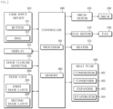
- a dryer 100 is one kind of clothes handling apparatuses.
- the cabinet 101 may include a base plate 102, a front cover 103, a top cover 104, and a side-rear cover 105.
- the user input device 110 and the display 115 for control of the dryer 100 may be disposed at an upper end of the front cover 103.
- the user input device 110 may receive a control command related to the dryer 100 from the user and output an electrical signal corresponding to the received control command to the controller 180.
- the display 115 may display an operational state of the dryer 100 and a control command from the user. For example, the display 115 may display a drying course selected by the user and display the time remaining until the end of drying during operation of the dryer 100.
- the display 115 may be implemented using various types of known displays such as a light emitting diode (LED) panel, an organic light emitting diode (OLED) panel, or a liquid crystal display (LCD) panel.
- LED light emitting diode
- OLED organic light emitting diode
- LCD liquid crystal display
- the display 115 is not limited thereto and may be any device capable of visually displaying various pieces of information related to the dryer 100.
- the display 115 may also employ a touch screen panel (TSP) configured to receive a control command from a user and display operational information corresponding to the received control command.
- TSP may include a display configured to display operational information and a control command which may be input by a user, a touch panel configured to detect coordinates of a point with which a part of the user's body has come in contact, and a touch screen controller configured to determine the control command input by the user on the basis of the coordinates of the point of contact detected by the touch panel.
- the touch screen controller may compare coordinates of the point of touch made by the user detected through the touch panel and coordinates of the control command displayed through the display and recognize the control command input by the user.
- the display 115 may receive a control signal related to the display from the controller 180 and display an image corresponding to the received control signal.
- the dryer 100 includes the drum 130 configured to accommodate an object to be dried and dry the object to be dried.
- the drum 130 may be rotatably installed in the cabinet 101.
- the drum 130 may be formed in a cylindrical shape whose center of rotation is formed in a front-rear, horizontal direction.
- a front panel 131 having an opening 131a formed therein to allow an object to be dried to be put in the drum 130 may be disposed at a front surface of the drum 130.
- a rear surface of the drum 130 may be closed by a rear panel 132 having an inlet 132a formed therein to allow introduction of high-temperature, dry air.
- An outlet 131b through which air used in drying the object to be dried is discharged may be provided in the front panel 131 of the drum 130.
- a filter 133 configured to collect foreign substances removed from the object to be dried may be installed in the outlet 131b. Accordingly, the foreign substances removed from the object to be dried may be collected by the filter 133.
- the drum 130 may receive a rotary force from a drum motor 135 and rotate.
- the drum 130 is connected to the drum motor 135 disposed in the cabinet 101 by a belt 136.
- the drum motor 135 may provide the rotary force to the drum 130 through the belt 136.
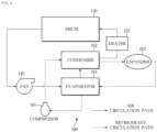
- One or more heat sources may be provided in the dryer 100, and the dryer 100 may supply high-temperature air to the drum 130 through the heat sources.
- the dryer 100 may include, as the heat sources, a heater 155 and a heat pump 160.
- dryers including a heat pump forming a refrigerant circuit may be classified into circulating type dryers and air discharge type dryers according to the flow of air being circulated.
- the circulating type dryer refers to a dryer capable of drying an object by circulating air without discharging or sucking air.
- the air discharge type dryer refers to a dryer which sucks outside air, uses the outside air in drying, and then discharges the outside air to the outside of the dryer.
- the dryer 100 may include the fan 140 configured to circulate air inside the drum 130.
- the fan 140 may suck air from inside the drum 130 and discharge the air to the duct 150. By the fan 140, the air inside the drum 130 may circulate through the drum 130 and the duct 150.
- the fan 140 may rotate by the fan motor 145.
- the fan motor 145 may rotate the fan 140 according to a control signal from the controller 180.
- the heater 155 and the heat pump 160 may be provided in the duct 150 through which the air inside the drum 130 circulates.
- the heat pump 160 includes a compressor 161, a condenser 162, an evaporator 164, and an expander 163.
- the compressor 161, the condenser 162, the expander 163, and the evaporator 164 may be seated on the base plate 102 at a bottom surface of the cabinet 101.
- the compressor 161 may compress refrigerant in a gaseous state to a high-temperature, high-pressure state and discharge the gaseous refrigerant in the high-temperature, high-pressure state.
- the compressor 161 may compress refrigerant through reciprocating movement of a piston or rotation of a rotor.
- the discharged refrigerant may be transferred to the condenser 162.
- the condenser 162 may condense the compressed gaseous refrigerant to a liquid.
- the condenser 162 may dissipate heat to surrounding portions thereof through the process of condensing the refrigerant.
- the condenser 162 may be provided in the duct 150 and heat the air through heat generated in the process of condensing the refrigerant.
- the heated air may be supplied to the drum 130.
- the liquid refrigerant condensed by the condenser 162 may be transferred to the expander 163.
- the expander 163 may expand the high-temperature, high-pressure liquid refrigerant condensed by the condenser 162 to liquid refrigerant in a low-pressure state.
- the expander 163 may include an expansion valve configured to adjust a pressure difference of the refrigerant.
- the expansion valve may include an electronic expansion valve (EEV) whose degree of opening may vary according to an electrical signal.
- EEV electronic expansion valve
- the dryer 100 may control a flow rate of the refrigerant by adjusting the degree of opening of the expander 163 through a control signal.
- the evaporator 164 may absorb heat from surrounding portions thereof through an evaporation process in which the low-pressure liquid refrigerant is changed to gaseous refrigerant.
- the evaporator 164 may be provided in the duct 150 and may cool air passing through the evaporator 164 in the evaporation process.
- Air around the evaporator 164 may be cooled by the evaporator 164, and, when a temperature of the air around the evaporator 164 becomes lower than the dew point, the air around the evaporator 164 may be condensed.
- the water due to condensation at the evaporator 164 may be collected by a water trap provided at a lower portion of the evaporator 164.
- the water collected by the water trap may move to a separate storage or be drained to the outside of the dryer 100.
- the absolute humidity of air passing through the evaporator 164 may be lowered. In other words, the amount of water vapor contained in the air passing through the evaporator 164 may be reduced.
- the dryer 100 may reduce the amount of water vapor contained in the air inside the drum 130 and dry the object to be dried.
- the evaporator 164 may be disposed more upstream than the condenser 162 on the basis of the flow of air due to the fan 140.
- the air circulating due to the fan 140 may be dried (water vapor may be condensed) by the evaporator 164 while the air passes through the evaporator 164, and then the air may be heated by the condenser 162 while passing through the condenser 162.
- the heater 166 may assist the condenser 162 in heating the air.
- the heater 155 may heat air in the duct 150 in response to a control signal from the controller 180. For example, before the condenser 162 of the heat pump 160 sufficiently heats the air in the duct 150, the heater 155 may assist the condenser 162 in heating the air in the duct 150.
- the temperature inside the drum 130 may more rapidly rise due to the heater 155 assisting the condenser 162, and the dryer 100 may more rapidly dry the object to be dried.
- the heater 155 may be disposed more downstream than the condenser 162 on the basis of the flow of air due to the fan 140.
- the heater 155 may be implemented through a heating coil.
- the heater 155 is not limited thereto and may be implemented through various other known devices.
- an opening 103a formed in a substantially circular shape when viewed from the front is provided in the front cover 103 of the cabinet 101.
- the opening 103a is opened or closed by a door 190 rotatably installed at the cabinet 101.
- the drum 130 may be configured to allow an object to be dried to be put in the drum 130 or allow a dried object to be taken out of the drum 130 when the opening 103a is opened by the door 190.
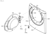
- the door 190 includes a door base 191 capable of opening or closing the opening 103a, a door hinge 192 configured to rotatably fix the door base 191 to one side of the cabinet 101 and a lever tip 193 provided to lock the door.
- the door base 191 may cover the opening 103a of the cabinet 101. At least a portion of the door base 191 may be formed of a transparent material to allow a user to view the inside of the drum 130.
- the door hinge 192 may be provided at one side of the door base 191.
- the door hinge 192 may rotatably fix the door base 191 to one side of the cabinet 101.
- the door base 191 may rotate about the door hinge 192.
- the door base 191 may close or open the opening 103a of the cabinet 101 while rotating about the door hinge 192.
- the door hinge 192 may be provided at one end of the door base 191 and removably installed at an outer side of the front cover 103 in the vicinity of the opening 103a of the cabinet 101.
- the door hinge 192 may be installed at a left side of the opening 103a or installed at a right side of the opening 103a.
- the door 190 may be rotatably fixed to the left side of the opening 103a or rotatably fixed to the right side of the opening 103a, depending on a position at which the door hinge 192 is installed.
- the door hinge 192 may be provided at a left side end of the door base 191 and fixed to the left side of the opening 103a of the front cover 103.
- the door 190 may rotate about the left side of the opening 103a of the cabinet 101 and the left side end of the door base 191.
- the door 190 may open the opening 103a by rotating leftward and close the opening 103a by rotating rightward.
- the door hinge 192 may be provided at a right side end of the door base 191 and fixed to the right side of the opening 103a of the front cover 103.
- the door 190 may rotate about the right side of the opening 103a of the cabinet 101 and the right side end of the door 190.
- the door 190 may open the opening 103a by rotating rightward and close the opening 103a by rotating leftward.
- the lever tip 193 may be installed at the opposite side of the door hinge 192 on the door base 191.
- the lever tip 193 may be disposed at the right side end of the door base 191 and be inserted into a hole in the right side of the opening 103a when the door 190 is closed. Also, when the door hinge 192 is disposed at the right side end of the door base 191, the lever tip 193 may be disposed at the left side end of the door base 191 and be inserted into a hole in the left side of the opening 103a when the door 190 is closed.
- the lever tip 193 may be inserted into a door lock 200, which will be described below, when the door 190 closes the opening 103a.
- the lever tip 193 may be fixed by the door lock 200.
- a hollow may be formed in the center of the lever tip 193, and the hollow of the lever tip 193 may be fixed by a catch cap which will be described below.
- the door 190 may keep the opening 103a closed and may be unable to be opened by an external force. In other words, the door 190 is locked by the door lock 200.
- the door 190 may be disposed at a position at which the door 190 opens the opening 103a and a position at which the door 190 closes the opening 103a. Also, when the door 190 is disposed at the position at which the door 190 closes the opening 103a, the door 190 may be locked by the door lock 200 or unlocked by the door lock 200.
- the door closure detector 170 may detect a closed state of the door 190 and an opened state of the door 190.
- the door closure detector 170 may include a push switch 171 disposed in the vicinity of the opening 103a of the cabinet 101.
- the push switch 171 may be unable to be pressed when the door 190 opens the opening 103a.
- the push switch 171 may be pressed by the door 190 when the door 190 closes the opening 103a.
- the door closure detector 170 may output a signal indicating that the door 190 is opened or a signal indicating that the door 190 is closed to the controller 180 on the basis of whether the push switch 171 is pressed. For example, the door closure detector 170 may output the signal indicating that the door 190 is opened to the controller 180 in response to the push switch 171 not being pressed. Also, the door closure detector 170 may output the signal indicating that the door 190 is closed to the controller 180 in response to the push switch 171 being pressed.
- the door lock 200 may include a first door latch 210 and a second door latch 220 which are capable of locking the door 190.
- the first door latch 210 and the second door latch 220 may be provided at an inner side of the front cover 103 of the cabinet 101. As illustrated in FIG. 6 , the first door latch 210 may be installed at the left side of the opening 103a when viewed from the rear of the front cover 103, that is, at the right side of the opening 103a when viewed from the front of the cabinet 101. As illustrated in FIG. 6 , the second door latch 220 may be installed at the right side of the opening 103a when viewed from the rear of the front cover 103, that is, at the left side of the opening 103a when viewed from the front of the cabinet 101.
- the door 190 may be rotatably fixed at the left side of the opening 103a.
- the user may fix the door hinge 192 at the left side of the opening 103a of the front cover 103 by using a screw 192a (see FIG. 5 ). Also, the user may fix a hole cover 194 at the right side of the opening 103a of the front cover 103 by using a screw 194a (see FIG. 5 ).
- the hole cover 194 may be installed at a hole at the opposite side of the door hinge 192, that is, the right side of the opening 103a of the front cover 103.
- the door hinge 192 is disposed at the left side end of the door base 191, and the lever tip 193 is disposed at the right side end of the door base 191.
- the door 190 is closed by rotating rightward from the left side, and the first door latch 210 provided at the right side of the opening 103a may fix the lever tip 193 of the door 190.
- the user may install the door 190 at the left side of the opening 103a of the front cover 103 without removing the front cover 103 from the cabinet 101.
- the door 190 may be rotatably fixed at the right side of the opening 103a.
- the user may fix the door hinge 192 to the right side of the opening 103a of the front cover 103 by using a screw (see FIG. 5 ). Also, the user may fix the hole cover 194 to the right side of the opening 103a of the front cover 103 by using a screw (see FIG. 5 ).
- the hole cover 194 may be installed at a hole at the opposite side of the door hinge 192, that is, the left side of the opening 103a of the front cover 103.
- the door hinge 192 is disposed at the right side end of the door base 191, and the lever tip 193 is disposed at the left side end of the door base 191.
- the door 190 is closed by rotating leftward from the right side, and the second door latch 220 provided at the left side of the opening 103a may fix the lever tip 193 of the door 190.
- the user may install the door 190 at the right side of the opening 103a of the front cover 103 without removing the front cover 103 from the cabinet 101.
- the first door latch 210 and the second door latch 220 may each fix the lever tip 193 of the door 190 in response to a door locking signal from the controller 180.
- the door lock 200 may lock the door 190 in response to the door locking signal from the controller 180.
- first door latch 210 and the second door latch 220 may each lock the door 190 depending on whether the door 190 is closed. In other words, the first door latch 210 and the second door latch 220 may lock the door 190 in a state in which the door 190 is closed.
- the door lock 200 may detect closure of the door 190 separately from the door closure detector 170. In other words, when the door 190 is not detected by the door closure detector 170, the door 190 is not locked, and the drying operation does not start. Also, when the door closure detector 170 detects the door 190 but closure of the door 190 is not detected by the door lock 200, the door 190 is not locked, and the drying operation does not start.
- the first door latch 210 and the second door latch 220 will be described in more detail below.
- the controller 180 may include a memory 182 configured to store a program and data for controlling the operation of the dryer 100 and a processor 181 configured to generate a control signal for controlling the operation of the dryer 100 according to the program and data stored in the memory 182.
- the memory 182 and the processor 181 may be implemented with separate chips or implemented with a single chip. Also, the controller 180 may include a plurality of memories or a plurality of processors.
- the memory 182 may store a program and data for controlling the drying operation according to each drying course.
- the memory 182 may store a speed of rotation of the drum 130 according to each drying course, a set temperature inside the drum 130 according to each drying course, and the like.
- the memory 182 may store a user input received through the user input device 110 or store information related to the operation of the dryer 100 (for example, the time remaining until the end of drying).
- the memory 182 may include a volatile memory such as a static random access memory (S-RAM) and a dynamic random access memory (D-RAM) and a non-volatile memory such as a read-only memory (ROM), an erasable programmable read-only memory (EPROM), and an electrically erasable programmable read-only memory (EEPROM).
- a volatile memory such as a static random access memory (S-RAM) and a dynamic random access memory (D-RAM)
- a non-volatile memory such as a read-only memory (ROM), an erasable programmable read-only memory (EPROM), and an electrically erasable programmable read-only memory (EEPROM).
- the memory 182 may include a single memory device or a plurality of memory devices.
- the processor 181 may process data according the program provided from the memory 182 and generate a control signal on the basis of a processing result.
- the processor 181 may process a user input received through the user input device 110 and an output signal of the door closure detector 170 and generate a control signal for controlling the door lock 200, the drum motor 135, the fan motor 145, the heater 155, and the heat pump 160 on the basis of a processing result.
- the processor 181 may output a control signal for controlling the door lock 200 to lock the door 190 to the door lock 200 in response to a user input indicating a start of an operation and a signal indicating closure of the door 190.
- the processor 181 may determine a drying course according to the user input.
- the processor 181 may determine a speed of rotation of the drum 130 according to the drying course and output a control signal corresponding to the determined speed of rotation to the drum motor 135.
- the processor 181 may determine a set temperature inside the drum 130 according to the drying course and output a control signal according to the determined set temperature to the heater 155 and the heat pump 160.
- the processor 181 may include an arithmetic circuit, a storage circuit, and a control circuit.
- the processor 181 may include a single chip or include a plurality of chips. Also, the processor 181 may include a single core or include a plurality of cores.
- FIG. 9 illustrates a simple configuration of the first door latch included in the clothes dryer according to an embodiment.
- the second door latch 220 may be configured to be vertically symmetrical to the first door latch 210.
- the first door latch 210 includes a first door locking terminal 211, a first neutral terminal 212, a first locking detection terminal 213, a first closure detection switch 214, a first solenoid 215, and a first locking detection switch 216.
- Each of the first door locking terminal 211, the first neutral terminal 212, and the first locking detection terminal 213 may be connected to the controller 180.
- the first closure detection switch 214 may detect whether the door 190 is closed. Specifically, the first closure detection switch 214 may detect whether the lever tip 193 disposed at the right side end of the door 190 is inserted into the first door latch 210 when the door 190 is installed at the left side of the opening 103a of the front cover 103.
- the lever tip 193 of the door 190 is not inserted into the first door latch 210 while the door 190 is open.
- the first closure detection switch 214 is opened (turned off).
- the lever tip 193 of the door 190 is inserted into the first door latch 210 when the door 190 is closed.
- the first closure detection switch 214 is closed (turned on).
- One end of the first closure detection switch 214 is connected to the first solenoid 215.
- the other end of the first closure detection switch 214 may be connected to the first neutral terminal 212 and the first locking detection switch 216.
- the first solenoid 215 may lock or unlock the door 190 in response to a door locking signal from the controller 180.
- the first solenoid 215 may generate a magnetic field in response to an electrical pulse.
- a first magnetic body inserted into the first solenoid 215 may perform translational movement due to the magnetic field of the first solenoid 215.
- the lever tip 193 of the door 190 may be fixed to the first door latch 210 due to the movement of the first magnetic body.
- the first solenoid 215 may convert an electrical signal to the translational movement of the first magnetic body, and the door 190 is locked due to the translational movement of the first magnetic body.
- the first magnetic body inserted into the first solenoid 215 interlocks with the first locking detection switch 216. Specifically, when the door 190 is locked due to the first magnetic body, simultaneously, the first magnetic body may close (turn on) the first locking detection switch 216. Also, when the door 190 is unlocked due to the first magnetic body, simultaneously, the first magnetic body may open (turn off) the first locking detection switch 216. In other words, the first solenoid 215 may open or close the first locking detection switch 216 in response to the door locking signal from the controller 180.
- One end of the first solenoid 215 is connected to the first door locking terminal 211, and the other end of the first solenoid 215 is connected to the first closure detection switch 214.
- the first door locking terminal 211, the first solenoid 215, the first closure detection switch 214, and the first neutral terminal 212 may be electrically connected to each other in that order.
- the first closure detection switch 214 When the first closure detection switch 214 is closed (turned on), a circuit formed of the first door locking terminal 211, the first solenoid 215, the first closure detection switch 214, the first neutral terminal 212, and the controller 180 may be closed. Therefore, the door locking signal output from the controller 180 may drive the first solenoid 215. In other words, when the first closure detection switch 214 is closed (turned on), the controller 180 may lock the door 190 and unlock the door 190 using the first solenoid 215.
- the circuit formed of the first door locking terminal 211, the first solenoid 215, the first closure detection switch 214, the first neutral terminal 212, and the controller 180 may be opened. Therefore, the door locking signal output from the controller 180 is not transmitted to the first solenoid 215. In other words, when the first closure detection switch 214 is opened (turned off), the controller 180 is unable to lock the door 190 using the first solenoid 215.
- the first closure detection switch 214 may detect whether the door 190 is locked. Specifically, when the door 190 is installed at the left side of the opening 103a of the front cover 103, the first locking detection switch 216 may detect whether the lever tip 193 disposed at the right side end of the door 190 is fixed to the first door latch 210.
- the first solenoid 215 may lock or unlock the door 190 in response to the door locking signal from the controller 180.
- the first solenoid 215 may simultaneously lock the door 190 and close (turn on) the first locking detection switch 216. Also, the first solenoid 215 may simultaneously unlock the door 190 and open (turn off) the first locking detection switch 216.
- One end of the first locking detection switch 216 is connected to the first neutral terminal 212.
- the other end of the first locking detection switch 216 may be connected to the first locking detection terminal 213.
- the first locking detection switch 216 When the first locking detection switch 216 is closed (turned on), a circuit formed of the first locking detection terminal 213, the first locking detection switch 216, the first neutral terminal 212, and the controller 180 may be closed. Therefore, through the first locking detection terminal 213, the controller 180 may identify that the door 190 is locked.
- the circuit formed of the first locking detection terminal 213, the first locking detection switch 216, the first neutral terminal 212, and the controller 180 may be opened. Therefore, through the first locking detection terminal 213, the controller 180 may identify that the door 190 is unlocked.
- the first closure detection switch 214 may be closed in response to closing of the door 190.
- the controller 180 may drive the first solenoid 215 so that the door 190 is locked.
- the first locking detection switch 216 may be closed (turned on) by driving of the first solenoid 215, and, from the closure of the first locking detection switch 216, the controller 180 may identify that the door 190 is locked.
- the second door latch 220 includes the same configuration as the first door latch 210.
- the second door latch 220 may include a second door locking terminal, a second neutral terminal, a second locking terminal, a second closure detection switch, a second solenoid, and a second locking detection switch.
- the elements of the second door latch 220 may be disposed to be vertically symmetrical to the elements of the first door latch 210.
- the first door locking terminal 211, the first neutral terminal 212, and the first locking detection terminal 213 are disposed in that order from left to right
- the second locking detection terminal, the second neutral terminal, and the second door locking terminal may be disposed in that order from left to right.
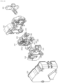
- FIG. 10 illustrates an exploded view of the first door latch included in the clothes dryer according to an embodiment.
- FIG. 11 illustrates a state in which the first door latch included in the clothes dryer according to an embodiment locks the door.
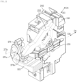
- the first door latch 210 may include a first housing 231 and a second housing 232 which are configured to protect the elements of the first door latch 210 from the outside.
- the first housing 231 is disposed behind the front cover 103 of the dryer 100, and the second housing 232 is disposed behind the first housing 231.
- a hole 231a into which the lever tip 193 of the door 190 is inserted may be provided in the first housing 231, and the lever tip 193 may pass through the hole 231a and be inserted into the first door latch 210.
- a first cover 241 in which an accommodation space for accommodating the elements of the first door latch 210 is formed is provided in the first housing 231 and the second housing 232.
- One side of the first cover 241 may be open, and the open side surface of the first cover 241 may be sealed by a second cover 242.
- the first solenoid 215, a first magnetic body 215a, the first door locking terminal 211, the first neutral terminal 212, the first locking detection terminal 213, and a switch plate 261 may be provided in the accommodation space of the first cover 241. Also, a door slider 251 and a locking slider 252 may be provided in front of the first cover 241, and a catch cap 271 may be provided at the left side of the first cover 241.
- the catch cap 271 may be rotatably seated on a third cover 243 disposed at the left side of the second cover 242.
- the catch cap 271 may be formed substantially in the shape of alphabet "A" and include a first leg 271a and a second leg 271b.
- the catch cap 271 may have a first posture in which a space between the first leg 271a and the second leg 271b faces the front.
- the lever tip 193 passes through the hole 231a of the first housing 231. Also, the lever tip 193 is seated in the space between the first leg 271a and the second leg 271b. The lever tip 193 applies a pushing force to the first leg 271a, and the catch cap 271 rotates about a rotating shaft 271c.
- the catch cap 271 may have a second posture in which the space between the first leg 271a and the second leg 271b faces the lower side.
- the door slider 251 may move in a first direction D1 (rightward in FIG. 11 ) as illustrated in FIG. 11 .
- the first closure detection switch 214 is closed (turned on).
- the first closure detection switch 214 may be formed of the switch plate 261 and the one end of the first solenoid 215.
- the switch plate 261 electrically comes in contact with the first neutral terminal 212.
- the switch plate 261 may be formed substantially in the shape of alphabet "V" and include a first contact plate 261a and a second contact plate 261b.
- the first contact plate 261a is spaced apart from the one end of the first solenoid 215 due to the door slider 251. In other words, the first closure detection switch 214 is opened (turned off).
- the first solenoid 215 and the first magnetic body 215a may be provided in the accommodation space of the first cover 241.
- the one end of the first solenoid 215 forms the first closure detection switch 214 together with the first contact plate 261a.
- the other end of the first solenoid 215 may be electrically connected to the first door locking terminal 211.
- the first magnetic body 215a may be movably inserted into the first solenoid 215.
- the first solenoid 215 may generate a magnetic field, and the first magnetic body 215a may perform translational movement due to the magnetic field of the first solenoid 215.
- the controller 180 may output a door locking signal in order to lock the door 190.
- the first solenoid 215 may lock the door 190 in response to the door locking signal from the controller 180.
- the first solenoid 215 When the first solenoid 215 generates a magnetic field due to the electrical signal (door locking signal) supplied from the controller 180, the first magnetic body 215a may move upward due to the magnetic field of the first solenoid 215.
- the movement of the first magnetic body 215a may be transferred to the locking slider 252 via mechanical devices included in the first door latch 210, and the locking slider 252 may move in a third direction D3 (toward the lower left side in FIG. 11 ).
- the first locking detection switch 216 is closed (turned on).
- the first locking detection switch 216 may be formed of the switch plate 261 and the first locking detection terminal 213.
- the switch plate 261 may include the first contact plate 261a and the second contact plate 261b.
- the second contact plate 261b is spaced apart from the first locking detection terminal 213 due to the locking slider 252. In other words, the first locking detection switch 216 is opened (turned off).
- the controller 180 may identify that the door 190 is unlocked. On the basis of the closing of the first locking detection switch 216, the controller 180 may identify that the door 190 is locked.
- the controller 180 may output a door unlocking signal in order to unlock the door 190.
- the first solenoid 215 may unlock the door 190 in response to the door unlocking signal from the controller 180.
- the first solenoid 215 When the first solenoid 215 generates a magnetic field due to the electrical signal (door unlocking signal) supplied from the controller 180, the first magnetic body 215a may move upward again due to the magnetic field of the first solenoid 215.
- the movement of the first magnetic body 215a may be transferred to the locking slider 252 via the mechanical devices included in the first door latch 210, and the locking slider 252 may move in a fourth direction D4 (toward the upper right side in FIG. 11 ).
- the second contact plate 261b is spaced apart from the first locking detection terminal 213. In other words, the first locking detection switch 216 is opened (turned off).
- the door slider 251 may move in a second direction D2 (leftward in FIG. 11 ).
- the first contact plate 261a is spaced apart from the one end of the first solenoid 215. In other words, the first closure detection switch 214 is opened (turned off).
- the first door latch 210 may include the door slider 251 which moves due to the lever tip 193, and, due to the movement of the door slider 251, the first closure detection switch 214 may be closed (turned on) or opened (turned off).
- the first door latch 210 includes the locking slider 252 which moves due to the operation of the first solenoid 215, and, due to the movement of the locking slider 252, the door 190 is locked or unlocked. Also, due to the movement of the locking slider 252, the first locking detection switch 216 may be closed (turned on) or opened (turned off).
- the second door latch 220 includes the same configuration as the first door latch 210.
- the second door latch 220 may include a second solenoid, a door slider, a locking slider, and a switch plate.
- the elements of the second door latch 220 may be disposed to be vertically symmetrical to the elements of the first door latch 210. Also, the elements of the second door latch 220 may move in a manner vertically symmetrical to the elements of the first door latch 210.
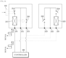
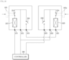
- FIG. 12 illustrates an example of connection between a controller and a door lock included in the clothes dryer according to an embodiment.
- FIGS. 13 , 14 , 15 and 16 illustrate operations of the door lock due to the connection illustrated in FIG. 12 .
- the dryer 100 includes the controller 180, the first door latch 210, and the second door latch 220.
- the first door locking terminal 211, the first neutral terminal 212, and the first locking detection terminal 213, which are connected to the controller 180, are provided in the first door latch 210.
- the first door latch 210 includes the first closure detection switch 214 configured to detect closure of the door 190, the first solenoid 215 configured to generate a dynamic force for locking the door 190, and the first locking detection switch 216 configured to detect locking of the door 190.
- the first closure detection switch 214, the first solenoid 215, and the first locking detection switch 216 which are included in the first door latch 210 may be disposed to be vertically symmetrical to the second closure detection switch 224, the second solenoid 225, and the second locking detection switch 226 which are included in the second door latch 220.
- the first door locking terminal 211, the first neutral terminal 212, and the first locking detection terminal 213 may be disposed to be vertically symmetrical to the second door locking terminal 221, the second neutral terminal 222, and the second locking detection terminal 223.
- the first door latch 210 and the second door latch 220 may be connected in parallel with the controller 180.
- the first door locking terminal 211 may be connected to the controller 180 together with the second door locking terminal 221
- the first neutral terminal 212 may be connected to the controller 180 together with the second neutral terminal 222.
- the first locking detection terminal 213 may be connected to the controller 180 together with the second locking detection terminal 223.
- the controller 180 may output a door locking signal, and the door locking signal of the controller 180 may be input to the first door latch 210 through the first door locking terminal 211 and be input to the second door latch 220 through the second door locking terminal 221. Since the first door latch 210 and the second door latch 220 are connected in parallel with the controller 180, a signal output from the controller 180 may be input to both the first door latch 210 and the second door latch 220.
- the door hinge 192 may be disposed at the left side of the opening 103a of the front cover 103, and the lever tip 193 may be disposed at the right side end of the door 190.
- the lever tip 193 When the door 190 is closed, as illustrated in FIG. 13 , the lever tip 193 may be inserted into the first door latch 210, and the first closure detection switch 214 may be closed (turned on) due to the lever tip 193.
- the second closure detection switch 224 of the second door latch 220 may be in an open (off) state.
- the controller 180 may output a door locking signal. Since the first closure detection switch 214 is in a closed (on) state, the door locking signal may be input to the first solenoid 215. The first solenoid 215 may be driven by the door locking signal, and, due to the driving of the first solenoid 215, the door 190 may be locked, and the first locking detection switch 216 may be closed (turned on).
- the door locking signal is not input to the second solenoid 225.
- the second solenoid 225 is not driven, and the second locking detection switch 226 may maintain being opened (turned off).
- the controller 180 may identify that the door 190 is locked.
- the door hinge 192 may be disposed at the right side of the opening 103a of the front cover 103, and the lever tip 193 may be disposed at the left side end of the door 190.
- the lever tip 193 When the door 190 is closed, as illustrated in FIG. 15 , the lever tip 193 may be inserted into the second door latch 220, and the second closure detection switch 224 may be closed (turned on) due to the lever tip 193.
- the first closure detection switch 214 of the first door latch 210 may be in an open (off) state.
- the controller 180 may output a door locking signal. Since the second closure detection switch 224 is in the closed (on) state, the door locking signal may be input to the second solenoid 225. The solenoid 225 may be driven by the door locking signal, and, due to the driving of the second solenoid 225, the door 190 may be locked, and the second locking detection switch 226 may be closed (turned on).
- the door locking signal is not input to the first solenoid 215.
- the first solenoid 215 is not driven, and the first locking detection switch 216 may maintain being opened (turned off).
- the controller 180 may identify that the door 190 is locked.
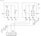
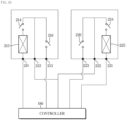
- FIG. 17 illustrates another example of the connection between the controller and the door lock included in the clothes dryer according to an embodiment.
- FIG. 18 illustrates an operation of the door lock due to the connection illustrated in FIG. 17 .
- the dryer 100 includes the controller 180, the first door latch 210, and the second door latch 220.
- the first door locking terminal 211, the first neutral terminal 212, and the first locking detection terminal 213 are provided in the first door latch 210, and the first door latch 210 includes the first closure detection switch 214, the first solenoid 215, and the first locking detection switch 216.
- the second door locking terminal 221, the second neutral terminal 222, and the second locking detection terminal 223 are provided in the second door latch 220, and the second door latch 220 includes the second closure detection switch 224, the second solenoid 225, and the second locking detection switch 226.
- the elements 211, 212, 213, 214, 215, and 216 of the first door latch 210 may be disposed to be vertically symmetrical to the elements 221, 222, 223, 224, 225, and 226 of the second door latch 220.
- the first door latch 210 and the second door latch 220 may be connected in series with the controller 180.
- the first door locking terminal 211 is connected to the controller 180
- the first locking detection terminal 213 is connected to the second door locking terminal 221
- the second locking detection terminal 223 is connected to the controller 180.
- the first neutral terminal 212 may be connected to the controller 180 together with the second neutral terminal 222.
- first solenoid 215, the first closure detection switch 214, the first locking detection switch 216, the second solenoid 225, the second closure detection switch 224, and the second locking detection switch 226 are connected in series with each other.
- the controller 180 may output a door locking signal, and the door locking signal of the controller 180 may be sequentially input to the first door latch 210 and the second door latch 220.
- the first solenoid 215 and the second solenoid 225 may be sequentially driven.
- the controller 180 may identify that the door 190 is locked. Since the first locking detection switch 216 and the second locking detection switch 226 are connected in series with each other, the controller 180 may identify that the door 190 is locked when both the first locking detection switch 216 and the second locking detection switch 226 are closed (turned on).
- the door hinge 192 may be disposed at the left side of the opening 103a of the front cover 103, and the lever tip 193 may be disposed at the right side end of the door 190.
- the lever tip 193 When the door 190 is closed, as illustrated in FIG. 18 , the lever tip 193 is inserted into the first door latch 210.
- the user may insert a fake lever tip 193a into the second door latch 220 in order to close (turn on) the second closure detection switch 224. Due to the fake lever tip 193a, the second closure detection switch 224 may be closed (turned on) at all times, and the first closure detection switch 214 may be closed (turned on) or opened (turned off) depending on whether the door 190 is closed or opened.
- the first solenoid 215 and the second solenoid 225 are either driven or not driven, depending on whether the first closure detection switch 214 is closed (turned on) or opened (turned off).
- the first solenoid 215 is driven by a primary door locking signal from the controller 180
- the second solenoid 225 is driven by a secondary door locking signal from the controller 180.
- the first solenoid 215 and the second solenoid 225 are not driven.
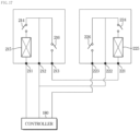
- FIG. 19 illustrates another example of the connection between the controller and the door lock included in the clothes dryer according to an embodiment.
- the first closure detection switch 214, the first solenoid 215, and the first locking detection switch 216 may be disposed to be vertically symmetrical to the second closure detection switch 224, the second solenoid 225, and the second locking detection switch 226.
- Each of the first door latch 210 and the second door latch 220 may be connected to the controller 180.
- the controller 180 may control the first door latch 210 and the second door latch 220 independently of each other. For example, the controller 180 may output a first door locking signal to the first door latch 210 and output a second door locking signal to the second door latch 220.
- the controller 180 may identify whether the door 190 is locked.
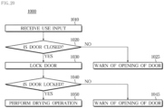
- FIG. 20 illustrates an operation of the clothes dryer according to an embodiment.
- the dryer 100 receives a user input (1010).
- a controller 180 may receive the user input through a user input device 110. For example, the user may select a drying course and input an operational command through the user input device 110.
- the dryer 100 determines whether a door 190 is closed (1020).
- the controller 180 may determine whether the door 190 is closed. For example, the controller 180 may identify whether the door 190 is closed on the basis of whether closure of the door 190 is detected by the door closure detector 170.
- the dryer 100 warns of the opening of the door 190 (1025).
- the controller 180 may display a message indicating opening of the door 190 on the display 115.
- the dryer 100 locks the door 190 (1030).
- a first door latch 210 and a second door latch 220 may be connected in parallel with the controller 180, or the first door latch 210 and the second door latch 220 may be connected in series with the controller 180. Alternatively, the first door latch 210 and the second door latch 220 may be separately connected to the controller 180.
- the controller 180 may output a door locking signal for locking the door 190 to the first door latch 210 and the second door latch 220.
- the dryer 100 determines whether the door 190 is locked (1040).
- Each of the first door latch 210 and the second door latch 220 which received the door locking signal from the controller 180 may lock the door 190 depending on whether the door 190 is closed and output the door locking signal depending on whether the door 190 is locked.
- the controller 180 may identify whether the door 190 is locked on the basis of whether the door locking signal is received.
- the dryer 100 warns of the opening of the door 190 (1045).
- he controller 180 may display a message indicating the opening of the door 190 on the display 115.
- the dryer 100 When the locking of the door 190 is detected (YES in 1020), the dryer 100 performs a drying operation (1050).
- the controller 180 may control the drum motor 135 to rotate the drum 130 and control the fan motor 145 to rotate the fan 140.
- the controller 180 may control the heat pump 160 to condense water vapor from air inside the drum 130 and control the heater 155 to heat the air inside the drum 130.
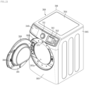
- FIG. 21 illustrates an exterior of a clothes washer according to an embodiment.
- FIG. 22 illustrates a configuration of the clothes washer according to an embodiment.
- FIG. 23 illustrates a side cross-section of the clothes washer according to an embodiment.
- FIG. 24 illustrates coupling between a main body and a door of the clothes washer according to an embodiment.
- a washer 300 is one kind of clothes handling apparatuses.
- the washer 300 refers to an apparatus which supplies water and detergent to a drum, in which an object to be washed is accommodated, and rotates the drum to wash the object to be washed.
- the object to be washed may include any object which may be washed by a mechanical action and a chemical action.
- the object to be washed is not limited and may be any object made of various kinds of fibers and fabrics, such as clothes and towels.
- the washer 300 includes a rectangular parallelepiped cabinet 301. Also, the washer 300 includes a user input device 310 provided inside or outside the cabinet 301, a display 315, a water tank 320, a drum 330, a drum motor 335, a detergent compartment 340, a water supply valve 350, a water drainage pump 360, a door closure detector 370, a door lock 400, and a controller 380.
- the cabinet 301 may include a base plate 302, a front cover 303, a top cover 304, and a side-rear cover 305.
- the user input device 310 and the display 315 for control of the washer 300 may be disposed at an upper end of the front cover 303.
- the user input device 310 includes a dial 311 and a button 312.
- the washer 300 may include different washing courses for washing different objects to be washed, and the user may select any one of a plurality of washing courses by rotating the dial 311.
- the washer 300 may include a power button for permitting or interrupting power supplied from an external power supply and an operational button for starting or stopping a washing operation of the washer 300.
- the user input device 310 may receive a control command related to the washer 300 from the user and output an electrical signal corresponding to the received control command to the controller 380.
- the display 315 may display an operational state of the washer 300 and a control command from the user. For example, the display 315 may display a washing course selected by the user and display the time remaining until the end of washing during operation of the washer 300.
- the display 315 may also employ a TSP configured to receive a control command from a user and display operational information corresponding to the received control command.
- a TSP configured to receive a control command from a user and display operational information corresponding to the received control command.
- the display 315 may receive a control signal related to the display from the controller 380 and display an image corresponding to the received control signal.
- the washer 300 includes the water tank 320 configured to accommodate water for washing.
- the water tank 320 may be installed to be able to vibrate in the cabinet 301 due to a damper 306.
- the damper 306 reduces the size of vibration transmitted to the cabinet 301 from the water tank 320 when the water tank 320 vibrates.
- the water tank 320 may be formed in a cylindrical shape.
- the water tank 320 may include a front portion 321 having an inlet 321a formed therein to allow an object to be washed to be put in the drum 330 and a rear portion 322 through which a rotating shaft 335a of the drum motor 335 passes.
- the washer 300 includes the drum 330 configured to accommodate an object to be washed and wash the object to be washed.
- the drum 330 may be rotatably installed in the water tank 320.
- the drum 330 may be formed in a cylindrical shape whose center of rotation is formed in the front-rear, horizontal direction.
- a front panel 331 having an opening 331a formed therein to allow an object to be washed to be put in the drum 330 may be disposed at a front surface of the drum 330.
- a rear surface of the drum 330 may be closed by a rear panel 332 connected to the rotating shaft 335a of the drum motor 335.
- the drum 330 may have a through-hole 333 formed therein to allow introduction of the water stored in the water tank 320 into the drum 330.
- the drum 330 may receive a rotary force from the drum motor 335 and rotate.
- the drum motor 335 is installed behind the water tank 320 and is connected to the drum 330 through the rotating shaft 335a passing through the water tank 320.
- the drum motor 335 may provide a rotary force to the drum 330 through the rotating shaft 335a.
- the detergent compartment 340 configured to store a detergent may be provided at an upper side of the water tank 320.
- the detergent compartment 340 may be connected to the water tank 320 through a connection tube 341.
- the water and the detergent may be supplied to the water tank 320 through the connection tube 341.
- a water supply tube 351 configured to connect an external water supply and the detergent compartment 340 to each other may be provided at the upper side of the water tank 320.
- a water supply valve 350 configured to close or open the water supply tube 351 may be installed in the water supply tube 351.
- the water moves to the detergent compartment 340 through the water supply tube 351 and is mixed with the detergent in the detergent compartment 340.
- the mixture of the water and the detergent may be supplied to the water tank 320 through the connection tube 341.
- a water drainage tube 361 configured to guide the water in the water tank 320 to the outside may be provided at a lower side of the water tank 320.
- the water drainage pump 360 configured to pump the water out of the water tank 320 may be installed in the water drainage tube 361.
- the water in the water tank 320 may be discharged to the outside of the washer 300.
- an opening 303a formed in a substantially circular shape when viewed from the front is provided in the front cover 303 of the cabinet 301.
- the opening 303a is opened or closed by a door 390 rotatably installed at the cabinet 301.
- the door 390 includes a door base 391, a door hinge 392, and a lever tip 393.
- the door base 391, the door hinge 392, and the lever tip 393 may be identical to the door base 191, the door hinge 192, and the lever tip 193 of the dryer 100, respectively.
- the door hinge 392 may be installed at a left side of the opening 303a or installed at a right side of the opening 303a.
- the door 390 may be rotatably fixed to the left side of the opening 303a or rotatably fixed to the right side of the opening 303a, depending on a position at which the door hinge 392 is installed.
- the lever tip 393 may be installed at the opposite side of the door hinge 392 on the door base 391.
- the lever tip 393 may be disposed at the right side end of the door base 391 and be inserted into a hole in the right side of the opening 303a when the door 390 is closed.
- the lever tip 393 may be disposed at the left side end of the door base 391 and be inserted into a hole in the left side of the opening 303a when the door 390 is closed.
- the door closure detector 370 may detect a closed state of the door 390 and an opened state of the door 390.
- the door closure detector 370 may include a push switch 371 disposed in the vicinity of the opening 303a of the cabinet 301.
- the push switch 371 may be identical to the push switch 171 of the dryer 100.
- the door lock 400 may include a first door latch 410 and a second door latch 420 which are capable of locking the door 390.
- the first door latch 410 and the second door latch 420 may be identical to the first door latch 210 and the second door latch 220 of the dryer 100.
- first door latch 410 and the second door latch 420 may be provided at an inner side of the front cover 303 of the cabinet 301.
- the first door latch 410 may be installed at the right side of the opening 303a when the cabinet 301 is viewed from the front.
- the second door latch 420 may be installed at the left side of the opening 303a when the cabinet 301 is viewed from the front.
- the door 390 When the door 390 is rotatably fixed to the left side of the opening 303a, the door 390 may be closed by rotating rightward from the left side, and the first door latch 410 provided at the right side of the opening 303a may fix the lever tip 393 of the door 390.
- the door 390 When the door 390 is rotatably fixed to the right side of the opening 303a, the door 390 may be closed by rotating leftward from the right side, and the second door latch 420 provided at the left side of the opening 303a may fix the lever tip 393 of the door 390.
- the first door latch 410 and the second door latch 420 may be configured to be symmetrical to each other.
- the first door latch 410 may include a first closure detection switch, a first solenoid, and a first locking detection switch
- the second door latch 420 may include a second closure detection switch, a second solenoid, and a second locking detection switch.
- the first closure detection switch, the first solenoid, and the first locking detection switch may be disposed to be vertically symmetrical to the second closure detection switch, the second solenoid, and the second locking detection switch.
- the controller 380 may include a memory 382 configured to store a program and data for controlling the operation of the washer 300 and a processor 381 configured to generate a control signal for controlling the operation of the washer 300 according to the program and data stored in the memory 382.
- the memory 382 and the processor 381 may be implemented with separate chips or implemented with a single chip.
- the controller 380 may include a plurality of memories or a plurality of processors.
- a computer-readable recording medium may include all type of recording media in which computer-readable instructions are stored.
- Examples of the computer-readable recording medium may include a ROM, a RAM, a magnetic tape, a magnetic disk, a flash memory, and an optical data storage.
Landscapes
- Engineering & Computer Science (AREA)
- Textile Engineering (AREA)
- Detail Structures Of Washing Machines And Dryers (AREA)
- Main Body Construction Of Washing Machines And Laundry Dryers (AREA)
- Control Of Washing Machine And Dryer (AREA)
- Holders For Apparel And Elements Relating To Apparel (AREA)
Claims (12)
- Vorrichtung zum Handhaben von Kleidungsstücken, umfassend:ein Gehäuse (101, 301), das eine Öffnung (103a, 303a) aufweist, die in einer vorderen Fläche (103, 303) des Gehäuses gebildet ist;eine Türverriegelung (200, 400), die einen ersten Türriegel (210, 410), der an einer rechten Seite der Öffnung an dem Gehäuse angebracht ist, und einen zweiten Türriegel (220, 420) beinhaltet, der an einer linken Seite der Öffnung an dem Gehäuse angebracht ist;eine Tür (190, 390), die entweder an der linken Seite der Öffnung oder an der rechten Seite der Öffnung anbringbar ist, sodass sie zum Öffnen oder Schließen der Öffnung drehbar ist, und,wenn die Tür an der linken Seite der Öffnung angebracht ist, die Tür durch den ersten Türriegel verriegelbar ist und,wenn die Tür an der rechten Seite der Öffnung angebracht ist, die Tür durch den zweiten Türriegel verriegelbar ist,dadurch gekennzeichnet, dassder erste Türriegel (210, 410) und der zweite Türriegel (220, 420) jeweils Folgendes beinhalten:einen Schließerkennungsschalter (214, 224),einen Elektromagneten (215, 225); undeinen Verriegelungserkennungsschalter (216, 226);wobei der Verriegelungserkennungsschalter dazu konfiguriert ist, eine Verriegelung der Tür zu erkennen, und die Vorrichtung zum Handhaben von Kleidungsstücken ferner Folgendes umfasst:eine Schließerkennungseinrichtung (170), die dazu konfiguriert ist, ein Schließen der Tür zu erkennen, undeine Steuereinrichtung (180, 380), die zu Folgendem konfiguriert ist:Steuern der Türverriegelung, um die Tür zu verriegeln, wenn die Schließerkennungseinrichtung ein Schließen der Tür erkennt, undSteuern der Vorrichtung zum Handhaben von Kleidungsstücken, um einen Start eines Trocknungsvorgangs der Vorrichtung zum Handhaben von Kleidungsstücken zu ermöglichen, wenn sowohl die Schließerkennungseinrichtung ein Schließen der Tür erkennt als auch der Verriegelungserkennungsschalter ein Verriegeln der Tür erkennt, undSteuern der Vorrichtung zum Handhaben von Kleidungsstücken, um den Start des Trockenvorgangs zu verhindern, wenn die Schließerkennungseinrichtung (170) ein Schließen der Tür erkennt, der Verriegelungserkennungsschalter (216, 226) jedoch kein Verriegeln der Tür erkennt, und wenn die Schließerkennungseinrichtung (170) kein Schließen der Tür erkennt, der Verriegelungserkennungsschalter (216, 226) jedoch ein Verriegeln der Tür erkennt,wobei der Schließerkennungsschalter (214, 224) bereitgestellt ist, um ein Schließen der Tür getrennt von der Schließerkennungseinrichtung (170) zu erkennen; undder Elektromagnet dazu bereitgestellt ist, die Tür auf Grundlage der Erkennung des Schließens der Tür durch den Schließerkennungsschalter zu verriegeln.
- Vorrichtung zum Handhaben von Kleidungsstücken nach Anspruch 1, wobei die Tür (190, 390) Folgendes beinhaltet:eine Türbasis (191, 391), eine Hebelspitze (193, 393), die an einem Ende der Türbasis angebracht ist; undein Türscharnier (192, 392), das an einem anderen Ende der Türbasis angebracht und abnehmbar an der vorderen Fläche (103) des Gehäuses (101, 301) entweder an der linken Seite der Öffnung (103a, 303a) angebracht ist, um dadurch die Tür (190, 390) an der linken Seite der Öffnung anzubringen, oder an der rechten Seite der Öffnung angebracht ist, um dadurch die Tür an der rechten Seite der Öffnung anzubringen.
- Vorrichtung zum Handhaben von Kleidungsstücken nach Anspruch 2, wobei die Hebelspitze (193, 393) folgendes ist:durch den ersten Türriegel (210, 410) verriegelbar, wenn das Türscharnier an der linken Seite der Öffnung (103a, 303a) angebracht ist; unddurch den zweiten Türriegel (220, 420) verriegelbar, wenn das Türscharnier an der rechten Seite der Öffnung angebracht ist.
- Vorrichtung zum Handhaben von Kleidungsstücken nach Anspruch 1, wobei der erste Türriegel (210, 410) und der zweite Türriegel (220, 420) parallel zu der Steuereinrichtung (180, 380) verbunden sind.
- Vorrichtung zum Handhaben von Kleidungsstücken nach Anspruch 1, wobei der erste Türriegel (210, 410) und der zweite Türriegel (220, 420) in Reihe mit der Steuereinrichtung (180, 380) verbunden sind.
- Vorrichtung zum Handhaben von Kleidungsstücken nach Anspruch 1, wobei der erste Türriegel (210, 410) und der zweite Türriegel (220, 420) symmetrisch zueinander gebildet sind.
- Vorrichtung zum Handhaben von Kleidungsstücken nach Anspruch 1, wobei der Schließerkennungsschalter (214, 224), ein Verriegelungsschieber (252), der Elektromagnet (215) und der Verriegelungserkennungsschalter (216) des ersten Türriegels (210, 410) bilateral symmetrisch zu dem Schließerkennungsschalter (224), einem Verriegelungsschieber (252), dem Elektromagneten (225) und dem Verriegelungserkennungsschalter (226) des zweiten Türriegels (220, 420) angeordnet sind.
- Vorrichtung zum Handhaben von Kleidungsstücken nach Anspruch 1, wobei in jedem von dem ersten Türriegel (210, 410) und dem zweiten Türriegel (220, 420) Folgendes gilt:der Schließerkennungsschalter (214, 224) und der Elektromagnet (215, 225) sind in Reihe miteinander verbunden undder Verriegelungserkennungsschalter (216, 226) ist parallel zu dem Schließerkennungsschalter und dem Elektromagneten verbunden.
- Vorrichtung zum Handhaben von Kleidungsstücken nach Anspruch 8, wobei die Steuereinrichtung (180, 380) dazu konfiguriert ist, ein Türverriegelungssignal an den ersten Türriegel (210, 410) und den zweiten Türriegel (220, 420) auszugeben
wobei der Elektromagnet (215, 225) die Tür (190, 390) als Reaktion auf das Türverriegelungssignal verriegelt, während der Schließerkennungsschalter (214, 224) geschlossen ist. - Vorrichtung zum Handhaben von Kleidungsstücken nach Anspruch 9, wobei:der Verriegelungserkennungsschalter (216, 226) durch den Elektromagneten (215, 225) geschlossen wird; unddie Steuereinrichtung (180, 380) auf Grundlage davon, ob der Verriegelungserkennungsschalter geschlossen ist, identifiziert, ob die Tür (190, 390) verriegelt ist.
- Vorrichtung zum Handhaben von Kleidungsstücken nach Anspruch 1, wobei der erste Türriegel (210, 410) und der zweite Türriegel (220, 420) jeweils Folgendes beinhalten:eine von der Hebelspitze erfasste Fangkappe (271);einen Türschieber (251), der dazu konfiguriert ist, sich aufgrund davon, dass die Tür geschlossen wird, aus einer ersten Position in eine zweite Position zu bewegen und in der zweiten Position den Schließerkennungsschalter einzuschalten; undeinen Verriegelungsschieber (252), der dazu konfiguriert ist, sich aufgrund der Betätigung des Elektromagneten aus einer dritten Position in eine vierte Position zu bewegen und in der vierten Position die Verschlusskappe zu fixieren und den Verriegelungserkennungsschalter einzuschalten.
- Vorrichtung zum Handhaben von Kleidungsstücken nach Anspruch 1, wobei die Tür (190, 390) mittels Schrauben abnehmbar an der Frontabdeckung (103, 303) angebracht ist.
Applications Claiming Priority (3)
| Application Number | Priority Date | Filing Date | Title |
|---|---|---|---|
| KR1020180139308A KR102596966B1 (ko) | 2018-11-13 | 2018-11-13 | 의류 처리 장치 |
| PCT/KR2019/015448 WO2020101349A1 (en) | 2018-11-13 | 2019-11-13 | Clothes handling apparatus |
| EP19883679.3A EP3850142B1 (de) | 2018-11-13 | 2019-11-13 | Kleidunghandhabungsvorrichtung |
Related Parent Applications (2)
| Application Number | Title | Priority Date | Filing Date |
|---|---|---|---|
| EP19883679.3A Division EP3850142B1 (de) | 2018-11-13 | 2019-11-13 | Kleidunghandhabungsvorrichtung |
| EP19883679.3A Division-Into EP3850142B1 (de) | 2018-11-13 | 2019-11-13 | Kleidunghandhabungsvorrichtung |
Publications (4)
| Publication Number | Publication Date |
|---|---|
| EP4239119A2 EP4239119A2 (de) | 2023-09-06 |
| EP4239119A3 EP4239119A3 (de) | 2023-11-08 |
| EP4239119B1 true EP4239119B1 (de) | 2025-01-29 |
| EP4239119C0 EP4239119C0 (de) | 2025-01-29 |
Family
ID=70550051
Family Applications (2)
| Application Number | Title | Priority Date | Filing Date |
|---|---|---|---|
| EP19883679.3A Active EP3850142B1 (de) | 2018-11-13 | 2019-11-13 | Kleidunghandhabungsvorrichtung |
| EP23187263.1A Active EP4239119B1 (de) | 2018-11-13 | 2019-11-13 | Vorrichtung zum handhaben von kleidungsstücken |
Family Applications Before (1)
| Application Number | Title | Priority Date | Filing Date |
|---|---|---|---|
| EP19883679.3A Active EP3850142B1 (de) | 2018-11-13 | 2019-11-13 | Kleidunghandhabungsvorrichtung |
Country Status (5)
| Country | Link |
|---|---|
| US (1) | US11319660B2 (de) |
| EP (2) | EP3850142B1 (de) |
| KR (1) | KR102596966B1 (de) |
| CN (1) | CN112996960B (de) |
| WO (1) | WO2020101349A1 (de) |
Families Citing this family (3)
| Publication number | Priority date | Publication date | Assignee | Title |
|---|---|---|---|---|
| EP3757276A1 (de) * | 2019-06-28 | 2020-12-30 | LG Electronics Inc. | Wäschebehandlungsvorrichtung |
| EP4166709A4 (de) * | 2020-11-20 | 2023-12-27 | Samsung Electronics Co., Ltd. | Trockner und verfahren zur steuerung davon |
| US20230151537A1 (en) * | 2021-11-17 | 2023-05-18 | Whirlpool Corporation | Foreign substrate collector for a laundry appliance |
Family Cites Families (24)
| Publication number | Priority date | Publication date | Assignee | Title |
|---|---|---|---|---|
| US5879036A (en) * | 1996-09-19 | 1999-03-09 | Moline; Steven S. | Door interlock for an appliance such as a washer |
| CN1214170C (zh) * | 1997-12-12 | 2005-08-10 | 约翰·菲利普·薛瓦利埃 | 汽车门或闭合件的闩锁装置 |
| US6425316B1 (en) * | 2000-03-21 | 2002-07-30 | Thang Van Phan | Piston drive mechanism |
| US7363781B2 (en) * | 2004-12-09 | 2008-04-29 | Whirlpool Corporation | Reversible door |
| JP4834395B2 (ja) * | 2005-08-03 | 2011-12-14 | 日立アプライアンス株式会社 | 密閉形圧縮機 |
| KR100675742B1 (ko) * | 2005-08-08 | 2007-01-30 | 두얼메카닉스 주식회사 | 드럼세탁기 도어의 회전락장치 |
| JP4761983B2 (ja) * | 2006-01-30 | 2011-08-31 | 三洋電機株式会社 | ドラム式洗濯機 |
| JP4475317B2 (ja) * | 2007-10-18 | 2010-06-09 | パナソニック株式会社 | ドラム式洗濯機 |
| KR101467778B1 (ko) * | 2008-04-30 | 2014-12-10 | 엘지전자 주식회사 | 의류처리장치의 도어스위치어셈블리 |
| KR101565381B1 (ko) | 2008-09-19 | 2015-11-03 | 엘지전자 주식회사 | 도어 조립체 |
| DE102009044126B3 (de) * | 2009-09-29 | 2010-11-04 | Miele & Cie. Kg | Verschlussanordnung für eine Wäschebehandlungsmaschine |
| IT1396735B1 (it) | 2009-11-26 | 2012-12-14 | Bitron Spa | Dispositivo di chiusura porta per il portello di un elettrodomestico. |
| JP5592179B2 (ja) * | 2010-07-02 | 2014-09-17 | パナソニック株式会社 | 衣類処理装置 |
| KR20120008689A (ko) | 2010-07-19 | 2012-02-01 | 주식회사 대우일렉트로닉스 | 도어 잠금장치 |
| KR101772971B1 (ko) | 2011-09-26 | 2017-09-01 | 삼성전자주식회사 | 세탁물 처리장치 |
| WO2014161784A1 (en) * | 2013-04-05 | 2014-10-09 | Arcelik Anonim Sirketi | A washer/dryer comprising a lock |
| CN106163361B (zh) * | 2014-02-03 | 2019-02-19 | 罗德电工有限公司 | 用于家用电器的门锁定装置 |
| WO2015130247A1 (en) * | 2014-02-25 | 2015-09-03 | Fathi Kiliç | Washing machine with bidirectional door |
| KR20150131532A (ko) * | 2014-05-15 | 2015-11-25 | 삼성전자주식회사 | 세탁물 처리장치 |
| JP6311126B2 (ja) * | 2015-02-27 | 2018-04-18 | パナソニックIpマネジメント株式会社 | 洗濯機 |
| KR102512205B1 (ko) | 2016-02-18 | 2023-03-22 | 삼성전자주식회사 | 도어 락킹장치 및 이를 갖는 세탁기 |
| JP6883390B2 (ja) * | 2016-07-13 | 2021-06-09 | リンナイ株式会社 | 衣類乾燥機 |
| US10260265B2 (en) * | 2016-11-16 | 2019-04-16 | Whirlpool Corporation | Appliance door assembly |
| EP3330577A1 (de) * | 2016-11-30 | 2018-06-06 | ThyssenKrupp Metalúrgica Campo Limpo Ltda. | Kolben-pleuelstange-baugruppe |
-
2018
- 2018-11-13 KR KR1020180139308A patent/KR102596966B1/ko active Active
-
2019
- 2019-11-13 US US16/682,598 patent/US11319660B2/en active Active
- 2019-11-13 EP EP19883679.3A patent/EP3850142B1/de active Active
- 2019-11-13 EP EP23187263.1A patent/EP4239119B1/de active Active
- 2019-11-13 CN CN201980074286.9A patent/CN112996960B/zh active Active
- 2019-11-13 WO PCT/KR2019/015448 patent/WO2020101349A1/en not_active Ceased
Also Published As
| Publication number | Publication date |
|---|---|
| EP4239119A3 (de) | 2023-11-08 |
| CN112996960B (zh) | 2023-12-01 |
| CN112996960A (zh) | 2021-06-18 |
| EP3850142C0 (de) | 2023-08-30 |
| KR102596966B1 (ko) | 2023-11-02 |
| KR20200055545A (ko) | 2020-05-21 |
| US20200149212A1 (en) | 2020-05-14 |
| EP3850142B1 (de) | 2023-08-30 |
| EP4239119C0 (de) | 2025-01-29 |
| EP3850142A1 (de) | 2021-07-21 |
| EP3850142A4 (de) | 2021-11-03 |
| WO2020101349A1 (en) | 2020-05-22 |
| US11319660B2 (en) | 2022-05-03 |
| EP4239119A2 (de) | 2023-09-06 |
Similar Documents
| Publication | Publication Date | Title |
|---|---|---|
| EP3299512B1 (de) | Steuerungsverfahren für einen wäschetrockner und wäschetrockner | |
| EP4239119B1 (de) | Vorrichtung zum handhaben von kleidungsstücken | |
| EP2948583B1 (de) | Wäschebehandlungsvorrichtung | |
| US9903067B2 (en) | Laundry machine | |
| US11828015B2 (en) | Laundry processing apparatus and method of controlling the same | |
| US20100192639A1 (en) | Laundry treatment device | |
| US9885144B2 (en) | Clothes dryer | |
| RU2450093C2 (ru) | Способ управления бытовым электроприбором, в частности бытовой сушильной или стиральной машиной, и бытовой электроприбор | |
| JP2022501097A (ja) | 衣類処理装置及び衣類処理装置の制御方法 | |
| JP6352614B2 (ja) | 洗濯乾燥機 | |
| KR20120022364A (ko) | 세탁장치 | |
| JP2008212170A (ja) | 乾燥機 | |
| KR102861552B1 (ko) | 의류 처리 장치 및 그 제어 방법 | |
| US20230235498A1 (en) | Clothes dryer | |
| KR20170068820A (ko) | 건조기, 및 그 제어방법 | |
| US20080115539A1 (en) | Laundry apparatus | |
| JP2005027934A (ja) | 乾燥機 | |
| KR20230103826A (ko) | 건조기 및 그 제어방법 | |
| KR102804125B1 (ko) | 의류 처리 장치 | |
| KR102791986B1 (ko) | 의류 처리 장치 | |
| US20240328056A1 (en) | Interface and laundry treating apparatus having the same | |
| JP5440467B2 (ja) | ドラム式洗濯乾燥機 | |
| KR20240122249A (ko) | 건조기 및 그 제어 방법 | |
| JP2024179962A (ja) | 衣類処理装置及び衣類処理装置の制御方法 | |
| KR20240022030A (ko) | 의류 처리 장치 |
Legal Events
| Date | Code | Title | Description |
|---|---|---|---|
| PUAI | Public reference made under article 153(3) epc to a published international application that has entered the european phase |
Free format text: ORIGINAL CODE: 0009012 |
|
| STAA | Information on the status of an ep patent application or granted ep patent |
Free format text: STATUS: THE APPLICATION HAS BEEN PUBLISHED |
|
| AC | Divisional application: reference to earlier application |
Ref document number: 3850142 Country of ref document: EP Kind code of ref document: P |
|
| AK | Designated contracting states |
Kind code of ref document: A2 Designated state(s): AL AT BE BG CH CY CZ DE DK EE ES FI FR GB GR HR HU IE IS IT LI LT LU LV MC MK MT NL NO PL PT RO RS SE SI SK SM TR |
|
| REG | Reference to a national code |
Ref country code: DE Ref legal event code: R079 Free format text: PREVIOUS MAIN CLASS: D06F0058200000 Ipc: D06F0037100000 Ref document number: 602019065602 Country of ref document: DE |
|
| PUAL | Search report despatched |
Free format text: ORIGINAL CODE: 0009013 |
|
| AK | Designated contracting states |
Kind code of ref document: A3 Designated state(s): AL AT BE BG CH CY CZ DE DK EE ES FI FR GB GR HR HU IE IS IT LI LT LU LV MC MK MT NL NO PL PT RO RS SE SI SK SM TR |
|
| RIC1 | Information provided on ipc code assigned before grant |
Ipc: D06F 58/20 20060101ALI20231002BHEP Ipc: D06F 58/04 20060101ALI20231002BHEP Ipc: D06F 39/14 20060101ALI20231002BHEP Ipc: D06F 37/28 20060101ALI20231002BHEP Ipc: D06F 37/10 20060101AFI20231002BHEP |
|
| STAA | Information on the status of an ep patent application or granted ep patent |
Free format text: STATUS: REQUEST FOR EXAMINATION WAS MADE |
|
| 17P | Request for examination filed |
Effective date: 20240207 |
|
| RBV | Designated contracting states (corrected) |
Designated state(s): AL AT BE BG CH CY CZ DE DK EE ES FI FR GB GR HR HU IE IS IT LI LT LU LV MC MK MT NL NO PL PT RO RS SE SI SK SM TR |
|
| GRAP | Despatch of communication of intention to grant a patent |
Free format text: ORIGINAL CODE: EPIDOSNIGR1 |
|
| STAA | Information on the status of an ep patent application or granted ep patent |
Free format text: STATUS: GRANT OF PATENT IS INTENDED |
|
| INTG | Intention to grant announced |
Effective date: 20240905 |
|
| GRAS | Grant fee paid |
Free format text: ORIGINAL CODE: EPIDOSNIGR3 |
|
| GRAA | (expected) grant |
Free format text: ORIGINAL CODE: 0009210 |
|
| STAA | Information on the status of an ep patent application or granted ep patent |
Free format text: STATUS: THE PATENT HAS BEEN GRANTED |
|
| AC | Divisional application: reference to earlier application |
Ref document number: 3850142 Country of ref document: EP Kind code of ref document: P |
|
| AK | Designated contracting states |
Kind code of ref document: B1 Designated state(s): AL AT BE BG CH CY CZ DE DK EE ES FI FR GB GR HR HU IE IS IT LI LT LU LV MC MK MT NL NO PL PT RO RS SE SI SK SM TR |
|
| REG | Reference to a national code |
Ref country code: GB Ref legal event code: FG4D |
|
| REG | Reference to a national code |
Ref country code: CH Ref legal event code: EP |
|
| REG | Reference to a national code |
Ref country code: DE Ref legal event code: R096 Ref document number: 602019065602 Country of ref document: DE |
|
| REG | Reference to a national code |
Ref country code: IE Ref legal event code: FG4D |
|
| U01 | Request for unitary effect filed |
Effective date: 20250207 |
|
| U07 | Unitary effect registered |
Designated state(s): AT BE BG DE DK EE FI FR IT LT LU LV MT NL PT RO SE SI Effective date: 20250213 |
|
| PG25 | Lapsed in a contracting state [announced via postgrant information from national office to epo] |
Ref country code: RS Free format text: LAPSE BECAUSE OF FAILURE TO SUBMIT A TRANSLATION OF THE DESCRIPTION OR TO PAY THE FEE WITHIN THE PRESCRIBED TIME-LIMIT Effective date: 20250429 |
|
| PG25 | Lapsed in a contracting state [announced via postgrant information from national office to epo] |
Ref country code: PL Free format text: LAPSE BECAUSE OF FAILURE TO SUBMIT A TRANSLATION OF THE DESCRIPTION OR TO PAY THE FEE WITHIN THE PRESCRIBED TIME-LIMIT Effective date: 20250129 |
|
| PG25 | Lapsed in a contracting state [announced via postgrant information from national office to epo] |
Ref country code: ES Free format text: LAPSE BECAUSE OF FAILURE TO SUBMIT A TRANSLATION OF THE DESCRIPTION OR TO PAY THE FEE WITHIN THE PRESCRIBED TIME-LIMIT Effective date: 20250129 |
|
| PG25 | Lapsed in a contracting state [announced via postgrant information from national office to epo] |
Ref country code: IS Free format text: LAPSE BECAUSE OF FAILURE TO SUBMIT A TRANSLATION OF THE DESCRIPTION OR TO PAY THE FEE WITHIN THE PRESCRIBED TIME-LIMIT Effective date: 20250529 Ref country code: NO Free format text: LAPSE BECAUSE OF FAILURE TO SUBMIT A TRANSLATION OF THE DESCRIPTION OR TO PAY THE FEE WITHIN THE PRESCRIBED TIME-LIMIT Effective date: 20250429 |
|
| PG25 | Lapsed in a contracting state [announced via postgrant information from national office to epo] |
Ref country code: HR Free format text: LAPSE BECAUSE OF FAILURE TO SUBMIT A TRANSLATION OF THE DESCRIPTION OR TO PAY THE FEE WITHIN THE PRESCRIBED TIME-LIMIT Effective date: 20250129 |
|
| PG25 | Lapsed in a contracting state [announced via postgrant information from national office to epo] |
Ref country code: GR Free format text: LAPSE BECAUSE OF FAILURE TO SUBMIT A TRANSLATION OF THE DESCRIPTION OR TO PAY THE FEE WITHIN THE PRESCRIBED TIME-LIMIT Effective date: 20250430 |
|
| PG25 | Lapsed in a contracting state [announced via postgrant information from national office to epo] |
Ref country code: SM Free format text: LAPSE BECAUSE OF FAILURE TO SUBMIT A TRANSLATION OF THE DESCRIPTION OR TO PAY THE FEE WITHIN THE PRESCRIBED TIME-LIMIT Effective date: 20250129 |
|
| PG25 | Lapsed in a contracting state [announced via postgrant information from national office to epo] |
Ref country code: CZ Free format text: LAPSE BECAUSE OF FAILURE TO SUBMIT A TRANSLATION OF THE DESCRIPTION OR TO PAY THE FEE WITHIN THE PRESCRIBED TIME-LIMIT Effective date: 20250129 |
|
| PG25 | Lapsed in a contracting state [announced via postgrant information from national office to epo] |
Ref country code: SK Free format text: LAPSE BECAUSE OF FAILURE TO SUBMIT A TRANSLATION OF THE DESCRIPTION OR TO PAY THE FEE WITHIN THE PRESCRIBED TIME-LIMIT Effective date: 20250129 |