EP4238732A2 - Härtungssystem mit ringförmiger geometrie - Google Patents
Härtungssystem mit ringförmiger geometrie Download PDFInfo
- Publication number
- EP4238732A2 EP4238732A2 EP23177786.3A EP23177786A EP4238732A2 EP 4238732 A2 EP4238732 A2 EP 4238732A2 EP 23177786 A EP23177786 A EP 23177786A EP 4238732 A2 EP4238732 A2 EP 4238732A2
- Authority
- EP
- European Patent Office
- Prior art keywords
- curing
- radiation
- extrusion head
- sources
- curing radiation
- Prior art date
- Legal status (The legal status is an assumption and is not a legal conclusion. Google has not performed a legal analysis and makes no representation as to the accuracy of the status listed.)
- Pending
Links
Images





Classifications
-
- B—PERFORMING OPERATIONS; TRANSPORTING
- B29—WORKING OF PLASTICS; WORKING OF SUBSTANCES IN A PLASTIC STATE IN GENERAL
- B29C—SHAPING OR JOINING OF PLASTICS; SHAPING OF MATERIAL IN A PLASTIC STATE, NOT OTHERWISE PROVIDED FOR; AFTER-TREATMENT OF THE SHAPED PRODUCTS, e.g. REPAIRING
- B29C64/00—Additive manufacturing, i.e. manufacturing of three-dimensional [3D] objects by additive deposition, additive agglomeration or additive layering, e.g. by 3D printing, stereolithography or selective laser sintering
- B29C64/20—Apparatus for additive manufacturing; Details thereof or accessories therefor
- B29C64/264—Arrangements for irradiation
-
- B—PERFORMING OPERATIONS; TRANSPORTING
- B29—WORKING OF PLASTICS; WORKING OF SUBSTANCES IN A PLASTIC STATE IN GENERAL
- B29C—SHAPING OR JOINING OF PLASTICS; SHAPING OF MATERIAL IN A PLASTIC STATE, NOT OTHERWISE PROVIDED FOR; AFTER-TREATMENT OF THE SHAPED PRODUCTS, e.g. REPAIRING
- B29C35/00—Heating, cooling or curing, e.g. crosslinking or vulcanising; Apparatus therefor
- B29C35/02—Heating or curing, e.g. crosslinking or vulcanizing during moulding, e.g. in a mould
- B29C35/08—Heating or curing, e.g. crosslinking or vulcanizing during moulding, e.g. in a mould by wave energy or particle radiation
- B29C35/0805—Heating or curing, e.g. crosslinking or vulcanizing during moulding, e.g. in a mould by wave energy or particle radiation using electromagnetic radiation
-
- B—PERFORMING OPERATIONS; TRANSPORTING
- B29—WORKING OF PLASTICS; WORKING OF SUBSTANCES IN A PLASTIC STATE IN GENERAL
- B29C—SHAPING OR JOINING OF PLASTICS; SHAPING OF MATERIAL IN A PLASTIC STATE, NOT OTHERWISE PROVIDED FOR; AFTER-TREATMENT OF THE SHAPED PRODUCTS, e.g. REPAIRING
- B29C64/00—Additive manufacturing, i.e. manufacturing of three-dimensional [3D] objects by additive deposition, additive agglomeration or additive layering, e.g. by 3D printing, stereolithography or selective laser sintering
- B29C64/10—Processes of additive manufacturing
- B29C64/106—Processes of additive manufacturing using only liquids or viscous materials, e.g. depositing a continuous bead of viscous material
-
- B—PERFORMING OPERATIONS; TRANSPORTING
- B29—WORKING OF PLASTICS; WORKING OF SUBSTANCES IN A PLASTIC STATE IN GENERAL
- B29C—SHAPING OR JOINING OF PLASTICS; SHAPING OF MATERIAL IN A PLASTIC STATE, NOT OTHERWISE PROVIDED FOR; AFTER-TREATMENT OF THE SHAPED PRODUCTS, e.g. REPAIRING
- B29C64/00—Additive manufacturing, i.e. manufacturing of three-dimensional [3D] objects by additive deposition, additive agglomeration or additive layering, e.g. by 3D printing, stereolithography or selective laser sintering
- B29C64/10—Processes of additive manufacturing
- B29C64/106—Processes of additive manufacturing using only liquids or viscous materials, e.g. depositing a continuous bead of viscous material
- B29C64/118—Processes of additive manufacturing using only liquids or viscous materials, e.g. depositing a continuous bead of viscous material using filamentary material being melted, e.g. fused deposition modelling [FDM]
-
- B—PERFORMING OPERATIONS; TRANSPORTING
- B29—WORKING OF PLASTICS; WORKING OF SUBSTANCES IN A PLASTIC STATE IN GENERAL
- B29C—SHAPING OR JOINING OF PLASTICS; SHAPING OF MATERIAL IN A PLASTIC STATE, NOT OTHERWISE PROVIDED FOR; AFTER-TREATMENT OF THE SHAPED PRODUCTS, e.g. REPAIRING
- B29C64/00—Additive manufacturing, i.e. manufacturing of three-dimensional [3D] objects by additive deposition, additive agglomeration or additive layering, e.g. by 3D printing, stereolithography or selective laser sintering
- B29C64/10—Processes of additive manufacturing
- B29C64/106—Processes of additive manufacturing using only liquids or viscous materials, e.g. depositing a continuous bead of viscous material
- B29C64/124—Processes of additive manufacturing using only liquids or viscous materials, e.g. depositing a continuous bead of viscous material using layers of liquid which are selectively solidified
-
- B—PERFORMING OPERATIONS; TRANSPORTING
- B29—WORKING OF PLASTICS; WORKING OF SUBSTANCES IN A PLASTIC STATE IN GENERAL
- B29C—SHAPING OR JOINING OF PLASTICS; SHAPING OF MATERIAL IN A PLASTIC STATE, NOT OTHERWISE PROVIDED FOR; AFTER-TREATMENT OF THE SHAPED PRODUCTS, e.g. REPAIRING
- B29C64/00—Additive manufacturing, i.e. manufacturing of three-dimensional [3D] objects by additive deposition, additive agglomeration or additive layering, e.g. by 3D printing, stereolithography or selective laser sintering
- B29C64/20—Apparatus for additive manufacturing; Details thereof or accessories therefor
- B29C64/205—Means for applying layers
- B29C64/209—Heads; Nozzles
-
- B—PERFORMING OPERATIONS; TRANSPORTING
- B29—WORKING OF PLASTICS; WORKING OF SUBSTANCES IN A PLASTIC STATE IN GENERAL
- B29C—SHAPING OR JOINING OF PLASTICS; SHAPING OF MATERIAL IN A PLASTIC STATE, NOT OTHERWISE PROVIDED FOR; AFTER-TREATMENT OF THE SHAPED PRODUCTS, e.g. REPAIRING
- B29C64/00—Additive manufacturing, i.e. manufacturing of three-dimensional [3D] objects by additive deposition, additive agglomeration or additive layering, e.g. by 3D printing, stereolithography or selective laser sintering
- B29C64/20—Apparatus for additive manufacturing; Details thereof or accessories therefor
- B29C64/264—Arrangements for irradiation
- B29C64/277—Arrangements for irradiation using multiple radiation means, e.g. micromirrors or multiple light-emitting diodes [LED]
-
- B—PERFORMING OPERATIONS; TRANSPORTING
- B29—WORKING OF PLASTICS; WORKING OF SUBSTANCES IN A PLASTIC STATE IN GENERAL
- B29C—SHAPING OR JOINING OF PLASTICS; SHAPING OF MATERIAL IN A PLASTIC STATE, NOT OTHERWISE PROVIDED FOR; AFTER-TREATMENT OF THE SHAPED PRODUCTS, e.g. REPAIRING
- B29C64/00—Additive manufacturing, i.e. manufacturing of three-dimensional [3D] objects by additive deposition, additive agglomeration or additive layering, e.g. by 3D printing, stereolithography or selective laser sintering
- B29C64/20—Apparatus for additive manufacturing; Details thereof or accessories therefor
- B29C64/295—Heating elements
-
- B—PERFORMING OPERATIONS; TRANSPORTING
- B33—ADDITIVE MANUFACTURING TECHNOLOGY
- B33Y—ADDITIVE MANUFACTURING, i.e. MANUFACTURING OF THREE-DIMENSIONAL [3D] OBJECTS BY ADDITIVE DEPOSITION, ADDITIVE AGGLOMERATION OR ADDITIVE LAYERING, e.g. BY 3D PRINTING, STEREOLITHOGRAPHY OR SELECTIVE LASER SINTERING
- B33Y10/00—Processes of additive manufacturing
-
- B—PERFORMING OPERATIONS; TRANSPORTING
- B33—ADDITIVE MANUFACTURING TECHNOLOGY
- B33Y—ADDITIVE MANUFACTURING, i.e. MANUFACTURING OF THREE-DIMENSIONAL [3D] OBJECTS BY ADDITIVE DEPOSITION, ADDITIVE AGGLOMERATION OR ADDITIVE LAYERING, e.g. BY 3D PRINTING, STEREOLITHOGRAPHY OR SELECTIVE LASER SINTERING
- B33Y30/00—Apparatus for additive manufacturing; Details thereof or accessories therefor
-
- B—PERFORMING OPERATIONS; TRANSPORTING
- B33—ADDITIVE MANUFACTURING TECHNOLOGY
- B33Y—ADDITIVE MANUFACTURING, i.e. MANUFACTURING OF THREE-DIMENSIONAL [3D] OBJECTS BY ADDITIVE DEPOSITION, ADDITIVE AGGLOMERATION OR ADDITIVE LAYERING, e.g. BY 3D PRINTING, STEREOLITHOGRAPHY OR SELECTIVE LASER SINTERING
- B33Y40/00—Auxiliary operations or equipment, e.g. for material handling
- B33Y40/20—Post-treatment, e.g. curing, coating or polishing
-
- B—PERFORMING OPERATIONS; TRANSPORTING
- B29—WORKING OF PLASTICS; WORKING OF SUBSTANCES IN A PLASTIC STATE IN GENERAL
- B29C—SHAPING OR JOINING OF PLASTICS; SHAPING OF MATERIAL IN A PLASTIC STATE, NOT OTHERWISE PROVIDED FOR; AFTER-TREATMENT OF THE SHAPED PRODUCTS, e.g. REPAIRING
- B29C35/00—Heating, cooling or curing, e.g. crosslinking or vulcanising; Apparatus therefor
- B29C35/02—Heating or curing, e.g. crosslinking or vulcanizing during moulding, e.g. in a mould
- B29C35/08—Heating or curing, e.g. crosslinking or vulcanizing during moulding, e.g. in a mould by wave energy or particle radiation
- B29C35/0805—Heating or curing, e.g. crosslinking or vulcanizing during moulding, e.g. in a mould by wave energy or particle radiation using electromagnetic radiation
- B29C2035/0827—Heating or curing, e.g. crosslinking or vulcanizing during moulding, e.g. in a mould by wave energy or particle radiation using electromagnetic radiation using UV radiation
Definitions
- the apparatus and method are related to the field of additive manufacturing and particularly to curing of curable material layers deposited by additive manufacturing devices.
- Three dimensional objects manufacturing processes involve deposition of a curable resin material layer in an imagewise manner and curing or hardening of the deposited segments of the layer.
- the layers are deposited (added) on top of each other and hence the process is called an additive manufacturing process by means of which a computer generated 3D model is converted into a physical object.
- the process involves generation of a plurality of material layers of different or identical shape.
- the layers are laid down or deposited on top (or bottom) of each of the preceding layer until the amount of accumulated layers results in a desired three dimensional physical object.
- the material from which the layers of the three-dimensional physical object are generated could come in liquid, paste, powder, gel and other forms. Conversion of such materials into a solid form is typically performed by suitable actinic radiation or heat. Different manufacturing techniques such as inkjet printing, laser sintering, material extrusion and others are used for manufacture of 3D objects.
- Manufacturing of 3D objects spans over a large range of applications. This includes prototype manufacture, small runs of different products manufacture, decorations, sculptures, architectural models and other physical objects.
- the time required to build a three-dimensional object depends on various parameters such as for example, curing time of the resin material using UV radiation, the speed of adding solid or liquid material to the layer which depends on the material itself, layer thickness, the intensity of the curing agent and the desired resolution of the three-dimensional object details and others.
- curing time of the resin material using UV radiation the speed of adding solid or liquid material to the layer which depends on the material itself, layer thickness, the intensity of the curing agent and the desired resolution of the three-dimensional object details and others.
- manufacturing techniques and especially inkjet printing material is deposited in a raster deposition mode and curing is performed in flood illumination mode.
- Material extrusion supports manufacture of 3D objects in vector mode and the curing of the extruded material could be performed in local or regional curing mode.
- UV light sources are Ultraviolet (UV) light sources and in particular Light Emitting Diodes (LEDs).
- UV LED illuminators are used in various configurations such as linear arrays or two dimensional matrices and are employed as UV light flooding illuminators.
- the existing UV LED based curing sources do not provide sufficient energy to cure extruded curing materials used for 3D objects manufacture.
- the curing techniques currently employed do not allow for rapid throughput mainly due to low energy levels at the curing site requiring longer curing times.
- Transformation of linear distribution of radiation intensity provided by two liner sources into a limited area such as, for example, one generally circular zone (sector) with homogenous energy distribution provides almost maximal uniform level of radiation energy or fluence, uniformly distributed throughout the sector so that to effectively (fully) cure the deposited resin material.
- FIG. 1 is a schematic simplified illustration of an example of a vector printing system suitable for manufacture by additive printing of three-dimensional structures.
- vector printing system 100 includes a storage or material supply tank 102 adapted to store a curable material 104, such as, for example, a pseudoplastic high viscosity material, a pump 108 configured to agitate and shear thin the curable material 104, to reduce material 104 viscosity and cause the material to flow.
- Pump 108 in addition to agitation also develops a pressure higher than atmospheric pressure such that curable material 104 flows through a delivery tubing or system 112 to an extrusion head extrusion nozzle 116.
- the higher than atmospheric pressure developed by the pump is communicated to extrusion head 114 extrusion nozzle 116 and could be such as 0.1 bar to 30.0 bar and typically from 1.0 bar to 20.0 bar and sometimes 2.0 bar to 10.0 bar.
- Vector printing system 100 includes an X-Y-Z directional vector movement system 124 configured to move the extrusion nozzle 116 in 3D space, i.e., in a three directions (X-Y-Z).
- a printing table 120 could be made to move in a three coordinate system.
- the movement in 3D space, i.e. in three directions (X-Y-Z) could result from combined movement in two or three directions (X-Y-Z) of both the extrusion nozzle 116 and printing table 120.
- System 100 also includes a computer 128 configured to control operation of movement system 124, pump 108 performing the curable material steering operation and value or magnitude of the higher than atmospheric pressure.
- Computer 128 is further adapted to receive data regarding a three-dimensional object 132 being printed and generate from the received data the X-Y-Z directional vector movement commands and distance such that the curable material 104 is extruded through extrusion head 114 and extrusion nozzle 116 in an image wise manner.
- the X-Y-Z directional vector movement could be performed in a vector mode or raster mode, depending on the object to be printed.
- Computer 128 could also be configured to optimize the selection of the printing mode as well as select the radiation power output based on the characteristics of the object being printed and the curing requirements thereof.
- Vector printing system 100 further includes a curing system 150, which includes one or more sources of curing radiation 136.
- Source of curing radiation 136 could be UV LED such as FireFly TM or Phoseon FE300 commercially available from Phoseon Technology, Inc., Hillsboro OR 97124 USA.
- Source of curing radiation 136 can provide UV radiation with total UV power of up to 900W and wavelength range of 380-420 nm.
- a UV lamp such as for example, mercury vapor lamp model Shot 500 commercially available from CureUV, Inc., Delray Beach, FL 33445 USA can be employed.
- Source of curing radiation 136 operates in a continuous manner concurrently with the deposition of the curing material and the radiation is selected to cure and harden curable material 104.
- Computer 128 could also be configured to control operation of source of curing radiation 136 and synchronize it with the printing mode.
- computer 128 can receive data of a three-dimensional object 132 and generate from the received data the X-Y-Z directional vector movement commands and length of strips such as 138-1, 138-2 to be deposited one above or below the other, such that the curable material 104 extruded through extrusion (head) extrusion nozzle 116 in an image wise manner resembles a slice of object 132. In a similar manner a following strip or a portion of the curable material 104 is extruded.
- Fig. 2 which is a plan view simplified illustration of curing system for printing of 3-D objects 150
- source of curing radiation 136 as viewed from a direction indicated by an Arrow (K)
- Fig. 1 can include an array 202 of LEDs 204 arranged along a central longitudinal axis 206.
- axis 206 is parallel to surface 118 of table 120 ( Fig. 1 ).
- Each of LEDs 204 can provide a flux of radiation of 1 Watt, hence the total flux depends on the number of LEDs 204 in the array.
- Array 202 of LEDs 204 can be a linear array such as that depicted in Fig.
- the number of LED units per array 202 can vary between 10 and 40 LEDs. More commonly the array can include between 15 and 35 LEDs and most commonly the array can include between 20-30 LEDs producing a total flux of radiation of 20-30 Watt.
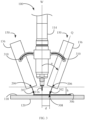
- Fig. 3 is an elevated lateral view simplified illustration of the positioning of the curing system for printing of 3-D objects 150 one or more sources of curing radiation 136 relative to extrusion head 114 and extrusion nozzle 116.
- one or more sources of curing radiation 136 can be moveably attached to extrusion head 114 flanking extrusion head 114 from at least one side thereof.
- two sources of curing radiation 136 including linear arrays 202 of LEDs 204 can be moveably ) attached to extrusion head 114 in a manner that supports change of an angle ( ⁇ ) with respect to axis W and distance to plane 306.
- Corresponding central axes 206 ( Fig. 2 ) of arrays 202 can be parallel to each other and to surface 118 of printing table 120 and emit a UV radiation beam 302 onto the surface of the extruded material 306 to be cured.
- sources of curing radiation 136 flank extrusion head 114 from opposite sides, sandwiching extrusion head 114 therebetween. It will be appreciated by persons skilled in the art that sources of curing radiation 136 can be attached to extrusion head 114 at various positions relative to each other and to extrusion nozzle 116 such as, for example, central longitudinal axis 206 of each of radiation sources 136 being normal to central longitudinal axis 206 of the other (e.g., as depicted in Fig. 8 ) and parallel to surface 118 of printing table 120 or at any other desired relative angle between central longitudinal axes 206 of any two or more sources of curing radiation 136.
- a single ring-form source of curing radiation 636 ( Fig. 6 ) can be attached to extrusion head 114 so that to concentrically surround extrusion nozzle 116.
- Attachment of one or more sources of curing radiation 136 to extrusion head 114 allows sources of curing radiation 136 to translate concurrently with extrusion head 114 and maintain a constant relationship between the homogenously illuminated area that could be, for example, of a round shape and nozzle 116 independent of travel direction.
- Sources of curing radiation 136 can follow the exact course of translation of extrusion head 114 extrusion nozzle 116 in 3D space during and throughout the curable material 104 deposition process including changes in elevation and back and forth movement as well as abrupt and sharp turns. Curing radiation from sources 136 can be applied in a continuous manner so that curable material 104 is deposited in an area already being impinged on by curing radiation. Hence, the curing system 150 of system for printing of 3-D objects 100 also supports almost immediate curing of the deposited curable material concurrently with or almost immediately following the deposition of the curable material as will be explained in greater detail below.
- Attachment of one or more sources of curing radiation 136 of the curing system for printing of 3-D objects 150 to extrusion head 114 supports the application of uniform and constant parameters of UV curing energy to the deposited curable material as it is being deposited by extrusion head 114 (i.e., concurrently with the deposition of curable material 104). These parameters can include, among others, the spot size and fluence (translated into heat) of the irradiated UV impinging on the deposited printing curable material as will be explained in greater detail below.
- Sources of curing radiation 136 of the curing system for printing of 3-D objects 150 can be attached to extrusion head 114 according to specific positioning parameters so that the central longitudinal axis 206 of array 202 (in Fig.
- Sources of curing radiation 136 are also attached to extrusion head 114 at an angle ( ⁇ ) between the central axis (W) of extrusion head 114 and central axis (Q) of sources of curing radiation 136 so that a point of impingement 308 of the center of UV radiation beam 302 from sources of curing radiation 136 on the surface of the layer being printed (i.e., the layer to be cured) is at a distance (d) from the central axis (W) of the extrusion head extrusion nozzle at any given time.
- Positioning parameters angle ( ⁇ ), elevation (h) and distance (d) can be adjusted and fixed as desired by loosening and tightening locking screws 310.
- angle ( ⁇ ) can be between 5 and 35 degrees, more commonly between 10 and 30 degrees and most commonly between 15 and 25 degrees.
- Elevation (h) can be in some cases between 5 and 35 mm, more commonly between 10 and 30 mm and most commonly between 15 and 25 mm.
- Distance (d) can be in some cases between 5 and 35 mm, more commonly between 10 and 30 mm and most commonly between 15 and 25 mm.
- This configuration supports the curable material deposition components, namely extrusion head 114 and extrusion nozzle 116 in concert with the curing system for printing of 3-D objects 150 sources of curing radiation 136 to act in unison as one single unit.
- the X-Y-Z directional vector movement system 124 configured to move extrusion nozzle 116 in 3D space (i.e., in three directions X, Y and Z) projects the same attributes on the curing system for printing of 3-D objects 150 sources of curing radiation 136 so that sources of curing radiation 136 are also and concurrently moved in 3D space, by directional vector movement system 124.
- X-Y-Z directional vector movement system 124 concurrently provides also curing system for printing of 3-D objects 150 sources of curing radiation with a vector directional movement that shadows the vector directional movement of extrusion head 114 and extrusion head 116.
- Fig. 4 is an elevated lateral plan view simplified illustration of the positioning of one or more sources of curing radiation 136 relative to extrusion head 114 and extrusion nozzle 116 and a graph of distribution of radiation energy over surface 118 of printing table 120.
- at least two sources of UV radiation such as sources of curing radiation 136 are attached to extrusion head 114 changes in positioning parameters angle ( ⁇ ), elevation (h) and distance (d) can affect the distribution pattern of the curing radiation energy impinging on surface 118 of printing table 120 thus affecting curing radiation parameters at the location of the deposited curable material 402 to be cured.
- each of sources of curing radiation 136 includes 25 LEDs for a total radiation fluence of 50W and are positioned at an optimal working point for the specific object to be printed so that to provide maximum radiation power and uniformity.
- Angle ( ⁇ ) is 20 degrees
- elevation (h) is 20 mm
- distance (d) is 20 mm.
- positioning sources of curing radiation 136 can narrow the distribution of effective (i.e., maximal uniform level of radiation energy operative to fully cure deposited curable material 402) radiation impinging on surface 118 to a sector (s) including deposited curable material 402. This can greatly contribute to the efficiency of the application of UV curing energy.
- the distribution of irradiant energy impinging on surface 118 is such that only a limited sector (s) (i.e., spot size) of the overall irradiated area of surface 118, which includes the location of deposited curable material 402 to be cured, provides almost maximal uniform level of irradiant energy or fluence, uniformly distributed throughout sector (s) so that to effectively (fully) cure deposited curable material 402.
- the area of sector (s) can be in some cases between 5 and 35 mm, more commonly between 10 and 30 mm and most commonly between 15 and 25 mm.
- the level of irradiant energy or fluence greatly drops outside the borders of sector (s) demonstrating the high efficiency of energy application in which energy is applied only where it is required.
- Fig. 5 is a mapping diagram of curing radiation fluence impinging on a surface, that when employing linear sources of curing radiation 136 such as that depicted in Fig. 2 and positioning them in accordance with the positioning parameters disclosed in the non-limiting example of Fig. 4 , the uniformity of curing radiation distribution impinging on surface 118 of printing table 120 can be maintained not only along a short axis (G) being normal to LED array 202 central longitudinal axis 206, but also along a long axis (M) centrally located in between LED arrays 202 and being parallel to central axes 206.
- G short axis
- M long axis
- sector (s), demarcated with a phantom-line border outline and designated numeral 502 is a deposited curable material effective curing sector being uniformly impinged upon by the highest (symbolized by the darkest shade) level of curing radiation energy.
- curable material deposition components namely extrusion head 114 and extrusion nozzle 116 in concert with the curing system for printing of 3-D objects 150 sources of curing radiation 136 operating in unison ensure that sector (s) has directional vector movement shadowing extrusion nozzle 116 and that curable material 104 is continuously deposited inside sector (s) being cured concurrently by curing system for printing of 3-D objects 150.
- sources of curing radiation 136 as explained above, attached to extrusion head 114 and in accordance with optimal positioning parameters described above, allows to achieve optimal and effective curing parameters, i.e., spot size and radiation flux in sector (s) concurrently or almost immediately following deposition of curable material 104 by extrusion nozzle 116.
- This allows to reduce printing throughput time by enabling an increase in the speed of translation of extrusion head 114, which depends on the curing of a first layer before depositing a second layer on top of the first layer.
- Computer 128 can be configured to optimize the required curing radiation power output based on the characteristics of the 3D object being manufactured and the curing parameters required thereby.
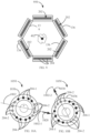
- Figs. 6A and 6B are an elevated side partial cross-section view and top view [from the direction indicated by an arrow (P)] simplified illustrations of another example of a curing system for printing of 3-D objects 650 for an additive printing process.
- source of curing radiation 636 can have a ring-form geometry, be attached to extrusion head 114 and positioned concentrically about extrusion head 114 extrusion nozzle 116.
- the cross-section 602 of ring-form source of curing radiation 636 can be angled at an angel ( ⁇ ) relative to central axis (W) of extrusion head 114 extrusion nozzle 116 similar to the example of Fig. 3 .
- the inner border 604 of the diverging UV radiation beams 605 emitted from each of the LEDs 204 in source of curing radiation 636 creates an evenly distributed uniform cone of radiation beams 606 to create a sector (s) of even curing energy distribution on surface 118 of printing table 120.
- the symmetrical geometry of ring-form source of curing radiation 636 brings about a uniform distribution of radiation curing energy throughout sector (s) in a similar fashion as that described in Fig. 5 .
- FIG. 7 depicts a curing system 750 including two semi-circle sources of curing radiation 736, similar in construction to ring-form source of curing radiation energy 636.
- Sources of curing radiation 736 can be attached to extrusion head 114 in a similar manner as depicted in the example of Fig. 3 and positioned concentrically about the extrusion head extrusion nozzle.
- Attachment of ring-form source of curing radiation energy 636 to extrusion head 114 can be done in a modular configuration so that source of curing radiation energy 636 can replace sources of curing radiation 136 if desired.
- the advantage of this configuration is in that though it can easily replace sources of curing radiation 136 and can benefit from the same modular method of attachment as that depicted in Fig. 3 , it can still preserve the symmetrical geometry of ring-form source of curing radiation 636 and bring about a uniformity of distribution of radiation curing energy throughout sector (s).
- Fig. 8 illustrates another example of a curing system 850.
- four sources 136 are attached on four sides of extrusion head 114 in a similar fashion as that depicted in Fig. 3 , the central longitudinal axis 206 of each array 202 being normal to central longitudinal axis 206 of the array 202 adjacent thereto.
- This configuration is simple to construct and complements the configuration depicted in Fig. 2 to provide a symmetrical application of curing radiation energy onto deposited curable material 402 by creating a sector (s) similar to that created by the examples in Figs. 6 and 7 .
- Fig. 9 is yet another example of a curing system for printing of 3-D objects.
- six sources 136 are attached on six sides of extrusion head 114 in a similar fashion as that depicted in Fig. 3 , forming as hexagon.
- This configuration is simple to construct and complements the configuration depicted in Fig. 2 to provide a symmetrical application of curing radiation energy onto deposited curable material 402 by creating a sector (s) similar to that created by the examples in Fig. 8 .
- Figs. 10A and 10B together referred to as Fig. 10 , depict an example, in which computer 128 can be configured to control operation of a curing system for printing of 3-D objects 1050 and source of curing radiation 636 similar to system 650 of Fig. 6 and synchronize system 1050 with the printing mode (i.e., movement of nozzle 116 during deposition of curable material 104.
- the printing mode i.e., movement of nozzle 116 during deposition of curable material 104.
- extrusion head 114, extrusion nozzle 116 and deposited material have been removed for purposes of clarity.
- Figure 10 illustrates vector movement of system 1050 shadowing vector directional vector movement of nozzle 116 (not shown) along a predetermined vector path depicted by a phantom line 1002.
- computer 128 has determined eight LEDs 204-1 symmetrically distributed on both sides of vector path 1002 to be sufficient for curing material deposited inside sector (s).
- operating LEDs 204-1 are darkened and non-operating LEDs 204-2 are clear in appearance.
- Fig. 10A shows system 500 moving along a first leg 1002-1 of predetermined vector path 1002 in a direction indicated by an arrow designated reference numeral 1020.
- vector path 1002 turns sharply to become leg 1002-2.
- computer 128 rearranges the order of LEDs by turning off unnecessary LEDs 204-1 and turning on necessary LEDs 204-2 without rotating curing system for printing of 3-D objects 1050 ring-form source of curing radiation 1036.
- a sector (s) in which a uniformity of curing radiation energy distribution impinging on surface 118 of printing table 120 can be maintained without rotation of curing system for printing of 3-D objects 1050 source of curing radiation 1036 but by controlling individual LEDs as determined by computer 128.
- System for printing of 3-D objects 1100 includes a tiered curing system for printing of 3-D objects 1150 including two or more sources of curing radiation 136 that can be moveably attached to extrusion head 114 flanking extrusion head 114 and extrusion nozzle 116 from at least one side thereof in a similar fashion to that described above and depicted in Figs. 3 and 4 .
- each tier on either flank of extrusion head 114 nozzle 116 can be composed of two sources of curing radiation 136-1 and 136-2 arranged in a stepwise manner.
- the tiered configuration depicted in Fig. 11 allows to increase the flux of radiation to cure curable materials that require such an increased flux while maintaining the same spot size or sector (s) (e.g., Fig. 4 ) size and the movement qualities described above.
- Figs. 12A and 12B are lateral and plan view simplified illustrations of yet another example of a curing system for printing of 3-D objects.
- Fig. 12B illustrates a view of curing system 1250 taken from a direction indicated in Fig. 12A by an arrow designated reference letter (M).
- System for printing of 3-D objects 1200 includes a tiered curing system for printing of 3-D objects 1250 including two or more sources of curing radiation 1202 and 1204 that can be 636 can have a ring-form geometry and be attached to extrusion head 114 and positioned concentrically about extrusion head 114 and extrusion nozzle 116 in a similar fashion to that described above and depicted in Fig. 6 .
- each tier concentrically arranged about extrusion head 114 and nozzle 116 can be composed of two sources of curing radiation 1202 and 1204 arranged in a stepwise manner.
- the tiered configuration depicted in Fig. 12 allows to increase the flux of radiation to cure curable materials that require such an increased flux while maintaining the same spot size or sector (s) (e.g., Fig. 4 ) size and the movement qualities described above.
- Curing system for printing of 3-D objects 1250 can also be controlled by computer 128 so that to support directionality of the vector movement thereof, shadowing the concurrent directional vector movement of extrusion head 114 and nozzle 116.
Landscapes
- Engineering & Computer Science (AREA)
- Chemical & Material Sciences (AREA)
- Materials Engineering (AREA)
- Physics & Mathematics (AREA)
- Manufacturing & Machinery (AREA)
- Optics & Photonics (AREA)
- Mechanical Engineering (AREA)
- Health & Medical Sciences (AREA)
- Toxicology (AREA)
- Electromagnetism (AREA)
- Oral & Maxillofacial Surgery (AREA)
- Thermal Sciences (AREA)
- Microelectronics & Electronic Packaging (AREA)
Applications Claiming Priority (3)
| Application Number | Priority Date | Filing Date | Title |
|---|---|---|---|
| US201562110616P | 2015-02-02 | 2015-02-02 | |
| PCT/IL2016/050057 WO2016125138A2 (en) | 2015-02-02 | 2016-01-18 | A curing system for printing of 3d objects |
| EP16746221.7A EP3253545B1 (de) | 2015-02-02 | 2016-01-18 | Aushärtungssystem zum drucken von 3d-objekten |
Related Parent Applications (2)
| Application Number | Title | Priority Date | Filing Date |
|---|---|---|---|
| EP16746221.7A Division EP3253545B1 (de) | 2015-02-02 | 2016-01-18 | Aushärtungssystem zum drucken von 3d-objekten |
| EP16746221.7A Division-Into EP3253545B1 (de) | 2015-02-02 | 2016-01-18 | Aushärtungssystem zum drucken von 3d-objekten |
Publications (2)
| Publication Number | Publication Date |
|---|---|
| EP4238732A2 true EP4238732A2 (de) | 2023-09-06 |
| EP4238732A3 EP4238732A3 (de) | 2023-12-13 |
Family
ID=56564837
Family Applications (2)
| Application Number | Title | Priority Date | Filing Date |
|---|---|---|---|
| EP16746221.7A Active EP3253545B1 (de) | 2015-02-02 | 2016-01-18 | Aushärtungssystem zum drucken von 3d-objekten |
| EP23177786.3A Pending EP4238732A3 (de) | 2015-02-02 | 2016-01-18 | Härtungssystem mit ringförmiger geometrie |
Family Applications Before (1)
| Application Number | Title | Priority Date | Filing Date |
|---|---|---|---|
| EP16746221.7A Active EP3253545B1 (de) | 2015-02-02 | 2016-01-18 | Aushärtungssystem zum drucken von 3d-objekten |
Country Status (6)
| Country | Link |
|---|---|
| US (1) | US11117291B2 (de) |
| EP (2) | EP3253545B1 (de) |
| JP (2) | JP6625653B2 (de) |
| KR (2) | KR102803989B1 (de) |
| IL (1) | IL253646B (de) |
| WO (1) | WO2016125138A2 (de) |
Families Citing this family (75)
| Publication number | Priority date | Publication date | Assignee | Title |
|---|---|---|---|---|
| CN103747943B (zh) * | 2011-04-17 | 2017-05-24 | 斯特拉塔西斯有限公司 | 用于对象的增材制造的系统和方法 |
| US9511543B2 (en) | 2012-08-29 | 2016-12-06 | Cc3D Llc | Method and apparatus for continuous composite three-dimensional printing |
| US10279580B2 (en) | 2015-07-31 | 2019-05-07 | The Boeing Company | Method for additively manufacturing composite parts |
| US10195784B2 (en) | 2015-07-31 | 2019-02-05 | The Boeing Company | Systems for additively manufacturing composite parts |
| US10343330B2 (en) | 2015-07-31 | 2019-07-09 | The Boeing Company | Systems for additively manufacturing composite parts |
| US10343355B2 (en) | 2015-07-31 | 2019-07-09 | The Boeing Company | Systems for additively manufacturing composite parts |
| US10232570B2 (en) | 2015-07-31 | 2019-03-19 | The Boeing Company | Systems for additively manufacturing composite parts |
| US10232550B2 (en) | 2015-07-31 | 2019-03-19 | The Boeing Company | Systems for additively manufacturing composite parts |
| US10201941B2 (en) | 2015-07-31 | 2019-02-12 | The Boeing Company | Systems for additively manufacturing composite parts |
| KR101795559B1 (ko) * | 2016-01-07 | 2017-11-08 | 주식회사 티앤알바이오팹 | 열민감성 세포프린팅 조성물의 세포 프린팅 장치 |
| US20180065317A1 (en) * | 2016-09-06 | 2018-03-08 | Cc3D Llc | Additive manufacturing system having in-situ fiber splicing |
| US10759113B2 (en) * | 2016-09-06 | 2020-09-01 | Continuous Composites Inc. | Additive manufacturing system having trailing cure mechanism |
| US10901386B2 (en) | 2016-09-06 | 2021-01-26 | Continuous Composites Inc. | Systems and methods for controlling additive manufacturing |
| US10674101B2 (en) * | 2016-10-28 | 2020-06-02 | General Electric Company | Imaging devices for use with additive manufacturing systems and methods of imaging a build layer |
| US10457033B2 (en) | 2016-11-07 | 2019-10-29 | The Boeing Company | Systems and methods for additively manufacturing composite parts |
| US11440261B2 (en) | 2016-11-08 | 2022-09-13 | The Boeing Company | Systems and methods for thermal control of additive manufacturing |
| US10766241B2 (en) * | 2016-11-18 | 2020-09-08 | The Boeing Company | Systems and methods for additive manufacturing |
| US10843452B2 (en) | 2016-12-01 | 2020-11-24 | The Boeing Company | Systems and methods for cure control of additive manufacturing |
| CN106738882B (zh) * | 2017-01-04 | 2019-07-16 | 肇庆中能创智信息科技有限公司 | 一种节能型3d打印设备 |
| JP6664135B2 (ja) * | 2017-01-11 | 2020-03-13 | ナイトライド・セミコンダクター株式会社 | 三次元プリンタ |
| US10576683B2 (en) | 2017-01-16 | 2020-03-03 | The Boeing Company | Multi-part filaments for additive manufacturing and related systems and methods |
| CN106863798B (zh) * | 2017-02-16 | 2019-03-01 | 浙江大学 | 一种3d打印喷头 |
| US10759159B2 (en) | 2017-05-31 | 2020-09-01 | The Boeing Company | Feedstock lines for additive manufacturing |
| US10906240B2 (en) | 2017-06-29 | 2021-02-02 | Continuous Composites Inc. | Print head for additive manufacturing system |
| US10814550B2 (en) | 2017-07-06 | 2020-10-27 | The Boeing Company | Methods for additive manufacturing |
| US10821672B2 (en) | 2017-07-06 | 2020-11-03 | The Boeing Company | Methods for additive manufacturing |
| CN107322924A (zh) * | 2017-07-16 | 2017-11-07 | 北京科田高新技术有限公司 | 一种3d打印机用喷头系统 |
| WO2019023789A1 (en) * | 2017-08-01 | 2019-02-07 | Sammut Eric | METHOD AND APPARATUS FOR EXTRUSION OF VISCOUS MATERIAL FOR INDIRECT THREE DIMENSIONAL PRINTING OF METAL |
| CN107571497A (zh) * | 2017-10-22 | 2018-01-12 | 北京科田高新技术有限公司 | 一种3d打印机及其应用 |
| CN107521092A (zh) * | 2017-10-26 | 2017-12-29 | 北京科田高新技术有限公司 | 一种直写型3d打印机 |
| CN108068308A (zh) * | 2017-11-07 | 2018-05-25 | 北京科田高新技术有限公司 | 一种静电纺丝式3d打印机及其应用 |
| US11331854B2 (en) * | 2018-03-26 | 2022-05-17 | Arevo, Inc. | System and method for dispensing composite filaments for additive manufacturing |
| US20190322038A1 (en) * | 2018-04-23 | 2019-10-24 | General Electric Company | Apparatus and method for fabrication with curable resins by extrusion and photo curing |
| EP3569330A1 (de) * | 2018-05-15 | 2019-11-20 | Rolls-Royce Corporation | Generativ gefertigte legierungskomponenten |
| US11313243B2 (en) | 2018-07-12 | 2022-04-26 | Rolls-Royce North American Technologies, Inc. | Non-continuous abradable coatings |
| EP3856489A4 (de) * | 2018-09-26 | 2022-10-19 | Board of Trustees of the University of Arkansas | Harzextrusionsdruckkopf zum 3d-drucken |
| JP7114147B2 (ja) | 2018-10-02 | 2022-08-08 | エルジー・ケム・リミテッド | 成形装置及び成形体の製造方法 |
| JP6900603B2 (ja) * | 2018-10-12 | 2021-07-07 | 株式会社Uskテクノロジー | 光源装置 |
| US12280596B2 (en) | 2019-05-23 | 2025-04-22 | General Electric Company | Cleaning systems for additive manufacturing apparatuses and methods for using the same |
| JP7267462B2 (ja) * | 2019-05-23 | 2023-05-01 | ゼネラル・エレクトリック・カンパニイ | オブジェクト形成方法 |
| US12358227B2 (en) | 2019-05-23 | 2025-07-15 | General Electric Company | Fluid management and circulation systems for use in additive manufacturing apparatuses |
| EP3972818A1 (de) | 2019-05-23 | 2022-03-30 | General Electric Company | Generative fertigung von überzugsanordnungen mit sensoren und verfahren zu ihrer verwendung |
| WO2020237118A2 (en) | 2019-05-23 | 2020-11-26 | General Electric Company | Wiper arrays for use in additive manufacturing apparatuses |
| CN114126844A (zh) | 2019-05-23 | 2022-03-01 | 通用电气公司 | 用于增材制造设备的致动器组件及其使用方法 |
| US12233643B2 (en) | 2019-05-23 | 2025-02-25 | General Electric Company | Printing assemblies and methods for using the same |
| EP3972761A2 (de) | 2019-05-23 | 2022-03-30 | General Electric Company | Reinigungsflüssigkeiten zur verwendung in generativen fertigungsvorrichtungen und verfahren zur überwachung des zustandes und der leistung derselben |
| US12042988B2 (en) | 2019-05-23 | 2024-07-23 | General Electric Company | Additive manufacturing apparatuses and methods |
| US12076918B2 (en) | 2019-05-23 | 2024-09-03 | General Electric Company | Additive manufacturing apparatuses and methods for using the same |
| WO2020237142A1 (en) | 2019-05-23 | 2020-11-26 | General Electric Company | Additive manufacturing recoat assemblies including a vacuum and methods for using the same |
| US11318679B2 (en) * | 2019-06-25 | 2022-05-03 | Mighty Buildings, Inc. | 3D printer print head system with curing module on rotation platform |
| FR3098752A1 (fr) | 2019-07-17 | 2021-01-22 | A3D L'atelier Numerique | Dispositif d’imprimante 3D selon la technologie à dépôt de fil fondu, dite « FDM », destinée aux imprimantes 3D professionnelles grand format, en ce qu’elle remédie à un faible rendement lié à cette technologie |
| FR3098753A1 (fr) | 2019-07-18 | 2021-01-22 | A3D L'atelier Numerique | dispositif de filtration destiné aux imprimantes 3D, quelles que soient leur taille ou leur technologie, pour remédier aux inconvénients de diffusion de pollutions |
| CN110315744A (zh) * | 2019-07-19 | 2019-10-11 | 西安增材制造国家研究院有限公司 | 一种光敏聚合物打印光源集成装置及其控制方法 |
| US11724456B2 (en) * | 2019-09-18 | 2023-08-15 | Mighty Buildings, Inc. | Optical curing system for 3D printing |
| EP3822004A1 (de) | 2019-11-14 | 2021-05-19 | Rolls-Royce Corporation | Schmelzfilamentfertigung von verschleissbaren beschichtungen |
| US12459196B2 (en) | 2019-11-14 | 2025-11-04 | Rolls-Royce Corporation | Patterned filament for fused filament fabrication |
| US11623400B2 (en) | 2020-02-03 | 2023-04-11 | Advanced Solutions Life Sciences, Llc | Modular light source for curing of 3D printed biological and engineered materials |
| WO2021158211A1 (en) * | 2020-02-04 | 2021-08-12 | Hewlett-Packard Development Company, L.P. | Emitting systems |
| US12496766B2 (en) | 2020-05-01 | 2025-12-16 | Texas Tech University System | Methods of 3D printing thermosetting polymers and continuous fiber composites via in-situ self-propagation curing and systems thereof |
| US11760030B2 (en) | 2020-06-23 | 2023-09-19 | Continuous Composites Inc. | Systems and methods for controlling additive manufacturing |
| CN111674039A (zh) * | 2020-07-09 | 2020-09-18 | 哈尔滨坤程科技有限公司 | 一种光固化3d打印机 |
| CN112477121B (zh) * | 2020-10-27 | 2023-07-25 | 上海中航光电子有限公司 | 3d打印系统及3d打印方法 |
| US12263636B2 (en) | 2020-11-02 | 2025-04-01 | General Electric Company | In-process optical based monitoring and control of additive manufacturing processes |
| JP7600672B2 (ja) * | 2020-12-23 | 2024-12-17 | セイコーエプソン株式会社 | 立体物印刷装置および立体物印刷方法 |
| RU206982U1 (ru) * | 2020-12-30 | 2021-10-05 | Общество с ограниченной ответственностью "МайтиТех" | Печатающая головка для 3D-принтера |
| IT202100004481A1 (it) * | 2021-02-25 | 2022-08-25 | Caracol S R L | Metodo ed apparecchiatura perfezionati per stampa tridimensionale. |
| US12103253B2 (en) * | 2021-03-31 | 2024-10-01 | Mighty Buildings, Inc. | High intensity light curing for three-dimensional printing |
| US11999104B2 (en) * | 2021-03-31 | 2024-06-04 | Mighty Buildings, Inc. | Three-dimensional printing head with adjustable printing angle |
| US12589549B2 (en) * | 2021-04-27 | 2026-03-31 | General Electric Company | Systems and methods for additive manufacturing |
| US12172379B2 (en) | 2021-08-11 | 2024-12-24 | General Electric Company | Cleaning system for additive manufacturing |
| US12409496B2 (en) | 2022-04-27 | 2025-09-09 | The Boeing Company | Pre-heating methods for performing electron beam powder bed fusion |
| US12343933B2 (en) | 2022-08-25 | 2025-07-01 | The Boeing Company | Methods of additively manufacturing a manufactured component and systems that perform the methods |
| US12485621B2 (en) | 2022-08-25 | 2025-12-02 | The Boeing Company | Methods of additively manufacturing a manufactured component and systems that perform the methods |
| WO2024108229A1 (en) * | 2022-11-19 | 2024-05-23 | MCANANY, Yuliya | Hybrid system for thermal additive manufacturing |
| CN116408967B (zh) * | 2023-02-20 | 2024-10-15 | 四川大学 | 一种3d打印用固化装置及方法、3d打印系统及方法 |
Family Cites Families (13)
| Publication number | Priority date | Publication date | Assignee | Title |
|---|---|---|---|---|
| US6259962B1 (en) * | 1999-03-01 | 2001-07-10 | Objet Geometries Ltd. | Apparatus and method for three dimensional model printing |
| AU2003900180A0 (en) * | 2003-01-16 | 2003-01-30 | Silverbrook Research Pty Ltd | Method and apparatus (dam001) |
| DE602004008458T2 (de) * | 2003-05-01 | 2008-05-21 | Objet Geometries Ltd. | Rapid-prototyping-vorrichtung |
| JP4217882B2 (ja) * | 2003-05-15 | 2009-02-04 | セイコーエプソン株式会社 | 液滴硬化機構を含む部材形成装置 |
| US7250611B2 (en) * | 2003-12-02 | 2007-07-31 | 3M Innovative Properties Company | LED curing apparatus and method |
| US20100140849A1 (en) * | 2007-03-22 | 2010-06-10 | Stratasys, Inc. | Extrusion-based layered deposition systems using selective radiation exposure |
| US8979257B2 (en) | 2008-02-14 | 2015-03-17 | Hewlett-Packard Development Company, L.P. | Printing or coating apparatus and method |
| US8876513B2 (en) * | 2008-04-25 | 2014-11-04 | 3D Systems, Inc. | Selective deposition modeling using CW UV LED curing |
| EP2636534B1 (de) * | 2010-06-07 | 2015-04-29 | LUXeXcel Holding B.V. | Verfahren zum Drucken optischer Strukturen |
| CN103747943B (zh) * | 2011-04-17 | 2017-05-24 | 斯特拉塔西斯有限公司 | 用于对象的增材制造的系统和方法 |
| US20160144570A1 (en) * | 2013-06-17 | 2016-05-26 | Biomedical 3D Printing Co., Ltd. | Curing Apparatus for 3D Printer, Using Ultraviolet Light Emitting Diode |
| CN103921445B (zh) | 2014-05-04 | 2016-06-08 | 中山市东方博达电子科技有限公司 | 光固化3d打印方法及光固化3d打印系统 |
| US11458679B2 (en) * | 2014-09-26 | 2022-10-04 | Hewlett-Packard Development Company, L.P. | Lighting for additive manufacturing |
-
2016
- 2016-01-18 KR KR1020237021592A patent/KR102803989B1/ko active Active
- 2016-01-18 US US15/545,469 patent/US11117291B2/en active Active
- 2016-01-18 KR KR1020177023868A patent/KR20170110104A/ko not_active Ceased
- 2016-01-18 EP EP16746221.7A patent/EP3253545B1/de active Active
- 2016-01-18 JP JP2017540717A patent/JP6625653B2/ja active Active
- 2016-01-18 WO PCT/IL2016/050057 patent/WO2016125138A2/en not_active Ceased
- 2016-01-18 EP EP23177786.3A patent/EP4238732A3/de active Pending
-
2017
- 2017-07-25 IL IL253646A patent/IL253646B/en active IP Right Grant
-
2019
- 2019-11-27 JP JP2019214047A patent/JP6912549B2/ja active Active
Also Published As
| Publication number | Publication date |
|---|---|
| KR102803989B1 (ko) | 2025-05-07 |
| US20180311898A1 (en) | 2018-11-01 |
| EP3253545A2 (de) | 2017-12-13 |
| EP3253545C0 (de) | 2023-07-19 |
| KR20170110104A (ko) | 2017-10-10 |
| US11117291B2 (en) | 2021-09-14 |
| IL253646A0 (en) | 2017-09-28 |
| WO2016125138A3 (en) | 2016-11-24 |
| EP4238732A3 (de) | 2023-12-13 |
| EP3253545B1 (de) | 2023-07-19 |
| IL253646B (en) | 2021-05-31 |
| JP2018503543A (ja) | 2018-02-08 |
| WO2016125138A2 (en) | 2016-08-11 |
| JP6625653B2 (ja) | 2019-12-25 |
| KR20230104753A (ko) | 2023-07-10 |
| EP3253545A4 (de) | 2018-10-03 |
| JP6912549B2 (ja) | 2021-08-04 |
| JP2020049946A (ja) | 2020-04-02 |
Similar Documents
| Publication | Publication Date | Title |
|---|---|---|
| EP3253545B1 (de) | Aushärtungssystem zum drucken von 3d-objekten | |
| JP2018503543A5 (de) | ||
| US11712765B2 (en) | Diode laser fiber array for contour of powder bed fabrication or repair | |
| EP3012079A1 (de) | Härtungsvorrichtung für 3d-drucker unter verwendung einer uv-lichtemittierenden diode | |
| JP6566872B2 (ja) | 高解像度dlpプロジェクタ装置、及びその利用方法 | |
| EP3848180B1 (de) | Verfahren und system zum 3d-rotationsdruck | |
| JP2017502843A (ja) | 粉体床製造又は補修のためのダイオードレーザファイバーアレイ | |
| JP2018515380A (ja) | 付加製造装置と方法 | |
| CN108297401B (zh) | 具有点和区域扫描激光束的粉末床融合系统 | |
| CN108463329A (zh) | 用于制造三维物体的装置和方法 | |
| CN203843168U (zh) | 一种高能束增材制造大尺寸金属零部件的设备 | |
| US20200079010A1 (en) | Additive manufacturing method using an energy source and varying build material spacings and apparatus | |
| JP2013527809A (ja) | 印刷装置及び印刷装置を制御する方法 | |
| EP3906149B1 (de) | Verfahren und system zur steuerung eines kühlsystems im dreidimensionalen druck | |
| WO2017197015A1 (en) | Reflector and additive manufacturing system | |
| IL297709B1 (en) | Leveling system for three-dimensional printing | |
| RU2003104533A (ru) | Способ изготовления перфорированной трехмерной пленки (варианты) и пленка, изготовленная этим способом (варианты) | |
| JP7406240B2 (ja) | 3d印刷方法および3d印刷装置 | |
| US12623403B2 (en) | Method and system for manipulating curing radiation in three-dimensional printing | |
| CN210969947U (zh) | 一种多光束增材制造设备 | |
| IL321843A (en) | Waste removal for three-dimensional printing |
Legal Events
| Date | Code | Title | Description |
|---|---|---|---|
| PUAI | Public reference made under article 153(3) epc to a published international application that has entered the european phase |
Free format text: ORIGINAL CODE: 0009012 |
|
| STAA | Information on the status of an ep patent application or granted ep patent |
Free format text: STATUS: THE APPLICATION HAS BEEN PUBLISHED |
|
| AC | Divisional application: reference to earlier application |
Ref document number: 3253545 Country of ref document: EP Kind code of ref document: P |
|
| AK | Designated contracting states |
Kind code of ref document: A2 Designated state(s): AL AT BE BG CH CY CZ DE DK EE ES FI FR GB GR HR HU IE IS IT LI LT LU LV MC MK MT NL NO PL PT RO RS SE SI SK SM TR |
|
| PUAL | Search report despatched |
Free format text: ORIGINAL CODE: 0009013 |
|
| AK | Designated contracting states |
Kind code of ref document: A3 Designated state(s): AL AT BE BG CH CY CZ DE DK EE ES FI FR GB GR HR HU IE IS IT LI LT LU LV MC MK MT NL NO PL PT RO RS SE SI SK SM TR |
|
| RIC1 | Information provided on ipc code assigned before grant |
Ipc: B29C 64/264 20170101ALI20231108BHEP Ipc: B29C 64/209 20170101ALI20231108BHEP Ipc: B29C 64/118 20170101ALI20231108BHEP Ipc: B29C 64/106 20170101ALI20231108BHEP Ipc: B29C 35/08 20060101AFI20231108BHEP |
|
| STAA | Information on the status of an ep patent application or granted ep patent |
Free format text: STATUS: REQUEST FOR EXAMINATION WAS MADE |
|
| 17P | Request for examination filed |
Effective date: 20240523 |
|
| RBV | Designated contracting states (corrected) |
Designated state(s): AL AT BE BG CH CY CZ DE DK EE ES FI FR GB GR HR HU IE IS IT LI LT LU LV MC MK MT NL NO PL PT RO RS SE SI SK SM TR |
|
| GRAP | Despatch of communication of intention to grant a patent |
Free format text: ORIGINAL CODE: EPIDOSNIGR1 |
|
| STAA | Information on the status of an ep patent application or granted ep patent |
Free format text: STATUS: GRANT OF PATENT IS INTENDED |
|
| INTG | Intention to grant announced |
Effective date: 20260218 |