EP4238731A1 - Harzschneidevorrichtung, granulator und pelletherstellungsverfahren - Google Patents
Harzschneidevorrichtung, granulator und pelletherstellungsverfahren Download PDFInfo
- Publication number
- EP4238731A1 EP4238731A1 EP21885592.2A EP21885592A EP4238731A1 EP 4238731 A1 EP4238731 A1 EP 4238731A1 EP 21885592 A EP21885592 A EP 21885592A EP 4238731 A1 EP4238731 A1 EP 4238731A1
- Authority
- EP
- European Patent Office
- Prior art keywords
- rotation
- shaft
- cutter
- force
- resin
- Prior art date
- Legal status (The legal status is an assumption and is not a legal conclusion. Google has not performed a legal analysis and makes no representation as to the accuracy of the status listed.)
- Granted
Links
Images



Classifications
-
- B—PERFORMING OPERATIONS; TRANSPORTING
- B29—WORKING OF PLASTICS; WORKING OF SUBSTANCES IN A PLASTIC STATE IN GENERAL
- B29B—PREPARATION OR PRETREATMENT OF THE MATERIAL TO BE SHAPED; MAKING GRANULES OR PREFORMS; RECOVERY OF PLASTICS OR OTHER CONSTITUENTS OF WASTE MATERIAL CONTAINING PLASTICS
- B29B9/00—Making granules
- B29B9/02—Making granules by dividing preformed material
- B29B9/06—Making granules by dividing preformed material in the form of filamentary material, e.g. combined with extrusion
- B29B9/065—Making granules by dividing preformed material in the form of filamentary material, e.g. combined with extrusion under-water, e.g. underwater pelletizers
-
- B—PERFORMING OPERATIONS; TRANSPORTING
- B29—WORKING OF PLASTICS; WORKING OF SUBSTANCES IN A PLASTIC STATE IN GENERAL
- B29B—PREPARATION OR PRETREATMENT OF THE MATERIAL TO BE SHAPED; MAKING GRANULES OR PREFORMS; RECOVERY OF PLASTICS OR OTHER CONSTITUENTS OF WASTE MATERIAL CONTAINING PLASTICS
- B29B9/00—Making granules
- B29B9/02—Making granules by dividing preformed material
- B29B9/06—Making granules by dividing preformed material in the form of filamentary material, e.g. combined with extrusion
-
- B—PERFORMING OPERATIONS; TRANSPORTING
- B29—WORKING OF PLASTICS; WORKING OF SUBSTANCES IN A PLASTIC STATE IN GENERAL
- B29B—PREPARATION OR PRETREATMENT OF THE MATERIAL TO BE SHAPED; MAKING GRANULES OR PREFORMS; RECOVERY OF PLASTICS OR OTHER CONSTITUENTS OF WASTE MATERIAL CONTAINING PLASTICS
- B29B7/00—Mixing; Kneading
- B29B7/30—Mixing; Kneading continuous, with mechanical mixing or kneading devices
- B29B7/58—Component parts, details or accessories; Auxiliary operations
- B29B7/72—Measuring, controlling or regulating
- B29B7/728—Measuring data of the driving system, e.g. torque, speed, power, vibration
-
- B—PERFORMING OPERATIONS; TRANSPORTING
- B29—WORKING OF PLASTICS; WORKING OF SUBSTANCES IN A PLASTIC STATE IN GENERAL
- B29C—SHAPING OR JOINING OF PLASTICS; SHAPING OF MATERIAL IN A PLASTIC STATE, NOT OTHERWISE PROVIDED FOR; AFTER-TREATMENT OF THE SHAPED PRODUCTS, e.g. REPAIRING
- B29C48/00—Extrusion moulding, i.e. expressing the moulding material through a die or nozzle which imparts the desired form; Apparatus therefor
- B29C48/001—Combinations of extrusion moulding with other shaping operations
- B29C48/0022—Combinations of extrusion moulding with other shaping operations combined with cutting
-
- B—PERFORMING OPERATIONS; TRANSPORTING
- B29—WORKING OF PLASTICS; WORKING OF SUBSTANCES IN A PLASTIC STATE IN GENERAL
- B29C—SHAPING OR JOINING OF PLASTICS; SHAPING OF MATERIAL IN A PLASTIC STATE, NOT OTHERWISE PROVIDED FOR; AFTER-TREATMENT OF THE SHAPED PRODUCTS, e.g. REPAIRING
- B29C48/00—Extrusion moulding, i.e. expressing the moulding material through a die or nozzle which imparts the desired form; Apparatus therefor
- B29C48/03—Extrusion moulding, i.e. expressing the moulding material through a die or nozzle which imparts the desired form; Apparatus therefor characterised by the shape of the extruded material at extrusion
- B29C48/05—Filamentary, e.g. strands
-
- B—PERFORMING OPERATIONS; TRANSPORTING
- B29—WORKING OF PLASTICS; WORKING OF SUBSTANCES IN A PLASTIC STATE IN GENERAL
- B29C—SHAPING OR JOINING OF PLASTICS; SHAPING OF MATERIAL IN A PLASTIC STATE, NOT OTHERWISE PROVIDED FOR; AFTER-TREATMENT OF THE SHAPED PRODUCTS, e.g. REPAIRING
- B29C48/00—Extrusion moulding, i.e. expressing the moulding material through a die or nozzle which imparts the desired form; Apparatus therefor
- B29C48/25—Component parts, details or accessories; Auxiliary operations
- B29C48/30—Extrusion nozzles or dies
- B29C48/345—Extrusion nozzles comprising two or more adjacently arranged ports, for simultaneously extruding multiple strands, e.g. for pelletising
-
- B—PERFORMING OPERATIONS; TRANSPORTING
- B29—WORKING OF PLASTICS; WORKING OF SUBSTANCES IN A PLASTIC STATE IN GENERAL
- B29B—PREPARATION OR PRETREATMENT OF THE MATERIAL TO BE SHAPED; MAKING GRANULES OR PREFORMS; RECOVERY OF PLASTICS OR OTHER CONSTITUENTS OF WASTE MATERIAL CONTAINING PLASTICS
- B29B7/00—Mixing; Kneading
- B29B7/30—Mixing; Kneading continuous, with mechanical mixing or kneading devices
- B29B7/34—Mixing; Kneading continuous, with mechanical mixing or kneading devices with movable mixing or kneading devices
- B29B7/38—Mixing; Kneading continuous, with mechanical mixing or kneading devices with movable mixing or kneading devices rotary
- B29B7/40—Mixing; Kneading continuous, with mechanical mixing or kneading devices with movable mixing or kneading devices rotary with single shaft
- B29B7/42—Mixing; Kneading continuous, with mechanical mixing or kneading devices with movable mixing or kneading devices rotary with single shaft with screw or helix
Definitions
- the present invention relates to a resin cutter, a granulator and a pellet manufacturing method, and relates to, for example, a technique effectively applied to a technique of cutting a resin by using a plurality of cutter blades while controlling a cutter-blade pressing force that presses the plurality of cutter blades to a die to be constant.
- Patent Document 1 describes a technique of controlling the cutter-blade pressing force to be constant.
- Patent Document 1 Japanese Patent No. 3751014
- the resin cutter manufactures a pellet by using a rotating cutter blade to cut a resin discharged from a nozzle formed in a die.
- a rotating cutter blade to cut a resin discharged from a nozzle formed in a die.
- the cutter blade is worn by the sliding, and therefore, too large cutter-blade pressing force that presses the cutter blade to the die increases a wear amount of the cutter blade.
- a small cutter-blade pressing force separates the cutter blade from the die, and becomes a cause of cutting trouble that is failure to normally cut the resin to form the pellet. Therefore, in order to cause the resin cutter to normally cut the resin to form the pellet, it is necessary to control the cutter-blade pressing force to constantly have a suitable value.
- a controller for controlling a cutter-blade pressing force is configured to variably control each of a revolution number of a rotation shaft attached to a cutter head, a magnitude of a rotation-shaft forward force and a magnitude of a rotation-shaft backward force so as to achieve the constant cutter-blade pressing force.
- a granulator according to an embodiment includes the resin cutter having the above-described configuration.
- a resin discharged from a die is cut by a plurality of cutter blades while a revolution number of a rotation shaft is variably controlled by a revolution-number controller, while a magnitude of a rotation-shaft forward force is variably controlled by a rotation-shaft forward force controller, and while a magnitude of a rotation-shaft backward force is variably controlled by a rotation-shaft backward force controller, so as to achieve the constant cutter-blade pressing force.
- a cutter-blade pressing force can be controlled to be a constant force.
- FIG. 1 is a diagram showing a schematic configuration of a granulator system.
- a granulator system 100 includes: a granulator 10 including an extruder 1 and a resin cutter 2; a pipe 4; a pump 5; a dehydrator 6, a reservoir 7; a centrifugal dehydrating dryer 8 and an oscillating screen 9.
- the extruder 1 is configured to knead a resin raw material 20 by using a rotating screw, and to extrude the kneaded resin from a plurality of nozzles formed in a die of the resin cutter 2.
- the resin cutter 2 is configured to cut the molten resin extruded from the plurality of nozzles formed in the die by using a plurality of cutter blades to manufacture the pellet.
- the pipe 4 functions as a flow passage in which warm water (fluid) flows.
- the pump 5 has a function of circulating the warm water flowing in the pipe 4.
- the reservoir 7 is a storage bath for storing the warm water.
- the dehydrator 6 has a function of separating the pellet from the warm water, and the centrifugal dehydrating dryer 8 has a function of further drying the pellet.
- the oscillating screen 9 is configured to classify the pellet by size.
- the granulator system 100 configured as described above operates as follows. Specifically, the resin raw material 20 is fed to the extruder 1 first. Then, the resin raw material 20 fed to the extruder 1 is kneaded by the screw, and then, the molten resin is extruded from the plurality of nozzles formed in the die. The extruded resin is cut by the plurality of cutter blades formed in the resin cutter 2. The resin is cut inside a closed chamber in which the warm water is flowing. In this manner, the molten resin is cut to a pellet 30 having a predetermined size, and then, is cooled and solidified by the warm water. As described above, the solidified pellet 30 is manufactured by the granulator 10 including the extruder 1 and the resin cutter 2.
- the warm water is circulated between the reservoir 7 and the closed chamber by the pipe 4 and the pump 5.
- slurry 3 that is mixture of the warm water and the pellet 30 generated in the closed chamber is delivered to the dehydrator 6 through the pipe 4.
- the warm water and the pellet 30 are separated from each other, and the flow of the warm water is backed to the reservoir 7.
- the slurry 3 that is the mixture of a small amount of the warm water and the pellet 30 is delivered to the centrifugal dehydrating dryer 8. In the centrifugal dehydrating dryer 8, the small amount of the warm water adhered on the pellet 30 is separated.
- the dried pellet 30 separated from the small amount of the warm water by the centrifugal dehydrating dryer 8 is delivered to the oscillating screen 9, and the flow of the small amount of the warm water separated by the centrifugal dehydrating dryer 8 is backed to the reservoir 7. Then, the oscillating screen 9 classifies the pellet 30 by size.
- the pellet 30 can be manufactured by the granulator system 100.
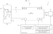
- FIG. 2 is a diagram showing a schematic configuration of the resin cutter.
- the resin cutter 2 includes a die 50, a cutter head 51, a rotation shaft 52, a motor 53, a sleeve 54, a housing 55, a closed chamber 60, an inflow port 60a and an outflow port 60b.
- the die 50 is arranged on a resin discharge side of the extruder that kneads and extrudes the resin, and this die 50 is provided with a plurality of nozzles. Each of the plurality of nozzles is configured to discharge the resin extruded from the extruder.
- the cutter head 51 is arranged to be pressed onto the die 50, and this cutter head 51 is provided with a plurality of cutter blades.
- the plurality of cutter blades have a function of cutting the resin discharged from the plurality of nozzles formed in the die 50 to form the pellet.
- the rotation shaft 52 is attached to the cutter head 51, and the motor 53 is attached to the rotation shaft 52.
- the cutter head 51 is configured to be rotatable because of being attached to the rotation shaft 52 rotated by the motor 53.
- the sleeve 54 that is slidable in a shaft direction of the rotation shaft 52 is arranged around the rotation shaft 52, and the housing 55 is arranged outside this sleeve 54.
- the rotation shaft 52 is configured to be rotatable relative to the sleeve 54 but not to be movable relative to the sleeve 54 in the shaft direction of the rotation shaft 52.
- the rotation shaft 52 and the sleeve 54 are configured to move together in the shaft direction of the rotation shaft 52.
- This sleeve 54 is configured to be movable relative to the housing 55 in the shaft direction of the rotation shaft 52.
- the closed chamber 60 configures a closed space in contact with the cutter head 51.
- This closed chamber 60 is provided with, for example, the inflow port 60a through which the fluid such as the warm water flows in and an outflow port through which the fluid and the pellet flow out of the closed chamber 60.
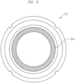
- FIG. 3 is a plan view showing a schematic configurational example of the die.
- the die 50 has, for example, a substantially circular shape as a plan shape, and includes a plurality of nozzles 50a. From each of the plurality of nozzles 50a, the molten resin kneaded by the extruder is discharged.
- FIG. 4 is a plan view showing a schematic configurational example of the cutter head.
- the cutter head 51 has, for example, a substantially circular shape as a plan shape, and this cutter head 51 is provided with a plurality of cutter blades 51a.
- Each of the plurality of cutter blades 51a has a substantially rectangular shape as a plan shape.
- the cutter head 51 is configured to be rotatable while being pressed onto the die 50. As a result, the resin discharged from the plurality of nozzles 50a formed in the die 50 is cut by the plurality of cutter blades 51a formed in the cutter head 51.
- the resin cutter 2 is configured as described above, and its operation will be explained below with reference to FIG. 2 .
- the resin kneaded by the extruder is discharged in the molten state from the plurality of nozzles formed in the die 50 to the closed chamber 60.
- the discharged molten resin is cut by the plurality of cutter blades formed in the cutter head 51 that is attached to the rotation shaft 52 rotated by the motor 53 and that rotates at a high speed.
- the cut resin is cooled and solidified to form the pellet by the warm water flowing through the inflow port 60a of the closed chamber 60.
- the warm water having flown into the closed chamber 60 flows out through the outflow port 60b of the closed chamber 60, and therefore, the formed pellet is also discharged through the outflow port 60b.
- the slurry that is the mixture of the discharged warm water and pellet is delivered to, for example, the dehydrator 6 through the pipe 4 as shown in FIG. 1 .
- the subsequent operations are as explained in the operation of the granulator system shown in FIG. 1 .
- the resin cutter 2 can manufacture the solidified pellet by cutting the molten resin.
- the cutter-blade pressing force that presses the plurality of cutter blades formed in the cutter head 51 onto the die 50 is needed to be controlled to a suitable constant value. This is because too large cutter-blade pressing force that presses the cutter blades onto the die increases the wear amount of the cutter blades since the pressing of the cutter blades onto the die 50 wears the cutter blades while a small cutter-blade pressing force separates the cutter blades from the die and becomes a cause of cutting trouble that is failure to normally cut the resin to form the pellet. Therefore, the resin cutter 2 has a configuration for controlling the cutter-blade pressing force to be a constant force. This configuration will be explained below.
- the resin cutter 2 includes a controller 70, a rotation-shaft forward force generator 80, and a rotation-shaft backward force generator 90.
- the rotation-shaft forward force generator 80 is configured to generate a rotation-shaft forward force "Ff" on the rotation shaft 52.
- the rotation-shaft forward force generator 80 is configured to generate the rotation-shaft forward force by using a pressure of a pressure medium injected into a first gap.
- a production of the pressure of the pressure medium and a pressure-receiving area of the first gap represents the rotation-shaft forward force "Ff”.
- This rotation-shaft forward force "Ff” is a force bringing the rotation shaft 52 (sleeve 54) to the die 50, and is a force generated by the rotation-shaft forward force generator 80.
- the rotation-shaft backward force generator 90 is configured to generate a rotation-shaft backward force "Fb" on the rotation shaft 52.
- the rotation-shaft backward force generator 90 is configured to generate the rotation-shaft backward force by using a pressure of a pressure medium injected into a second gap.
- a production of the pressure of the pressure medium and a pressure-receiving area of the second gap represents the rotation-shaft backward force "Fb”.
- This rotation-shaft backward force "Fb” is a force separating the rotation shaft 52 (sleeve 54) from the die 50, and is a force generated by the rotation-shaft backward force generator 90.
- the controller 70 is configured to control the cutter-blade pressing force that presses the plurality of cutter blades onto the die 50, and includes a revolution-number controller 71, a rotation-shaft forward force controller 72 and a rotation-shaft backward force controller 73.
- the revolution-number controller 71 is configured to control a revolution number of the rotation shaft 52. Specifically, this is configured to control the revolution number of the rotation shaft 52 by controlling the rotation of the motor 53 to which the rotation shaft 52 is attached.
- the rotation-shaft forward force controller 72 is configured to control the rotation-shaft forward force "Ff" by adjusting the pressure of the pressure medium injected into the first gap.
- the rotation-shaft backward force controller 73 is configured to control the rotation-shaft backward force "Fb" by adjusting the pressure of the pressure medium injected into the second gap.
- the controller 70 configured as described above is configured to control the cutter-blade pressing force expressed by the following relation formula to be the constant force.
- FIG. 5 is a diagram showing a schematic configuration of a principal part of the resin cutter.
- FIG. 5 shows the slide resistance force "Fr” and the backward force “Fw” caused by the fluid pressure of the fluid filling the closed chamber.
- each of the "Fw” and the “Fr” shows an almost constant value (constant) defined by the structure of the resin cutter 2, and can be previously estimated. Therefore, in order to keep the constant cutter-blade pressing force "F", the controller 70 of the resin cutter 2 controls the value of "Ff + Fs - Fb" to be constant. An operation example of this controller 70 will be explained below.
- FIG. 6 is a graph for explaining the operation example of the controller 70.
- a horizontal axis represents the revolution number (Nc) of the rotation shaft
- a vertical axis represents the force.
- a reason why the rotation-shaft backward force controller 73 controls the rotation-shaft backward force "Fb" to be constant even in the change of the revolution number Nc of the rotation shaft 52 is that the stability of the control and the easiness of the adjustment are to be emphasized.
- the variable control for the rotation-shaft forward force "Ff" by the rotation-shaft forward force controller 72 and the variable control for the rotation-shaft backward force "Fb" by the rotation-shaft backward force controller 73 make the control complicated.
- the constant cutter-blade pressing force "F" can be kept even in the change of the revolution number Nc of the rotation shaft 52.
- a size of the die 50 tends to be large. This is because the number of the nozzles 50a formed in the die 50 can be increased by the increase of the size of the die 50. In other words, this is because the increase of the number of the nozzles 50a formed in the die 50 can increase the number of pellets provided by cutting the resin discharged from the nozzles 50a by the cutter blades 51a. And, the increase of the size of the die 50 also increases a size of the cutter head 51 pressed onto the die 50. As a result, the number of the cutter blades 51a formed in the cutter head 51 is also increased.
- the manufacturing efficiency of the pellet can be improved by synergetic effect of the increase of the number of the nozzles 50a because of the increase of the size of the die 50 and the increase of the number of the cutter blades 51a because of the increase of the size of the cutter head 51.
- the increase of the number of the cutter blades 51a formed in the cutter head 51 increases the cutter-blade driving force "Fs". This is because it is clear that the cutter-blade driving force "Fs” is increased by the increase of the number of the cutter blades 51a since the cutter-blade driving force "Fs" is a force generated by rotation of the cutter blades 51a in the warm water inside the closed chamber 60, the cutter blades 51a being attached to the cutter head 51 to have an attack angle with respect to the rotation direction, as similar to a case of a propeller.
- the new findings having been found out by the present inventors are the findings in which it is difficult to keep the constant cutter-blade pressing force "F” only by the decrease of the rotation-shaft forward force "Ff” since the increase of the number of the cutter blades 51a formed in the cutter head 51 for improving the manufacturing efficiency of the pellet manufactured by the granulator system 100 increases the variation range of the cutter-blade driving force "Fs".
- FIG. 7 is a diagram for explaining that it is difficult to keep the constant cutter-blade pressing force "F” only by the decrease of the rotation-shaft forward force "Ff” performed by the rotation-shaft forward force controller 72.
- the variation range of the cutter-blade driving force "Fs" in the change of the revolution number Nc of the rotation shaft 52 is made larger in the case of the large number of the cutter blades 51a than the case of the small number of the cutter blades 51a. Therefore, in order to keep the constant cutter-blade pressing force "F", it is also necessary to increase the variation range of the rotation-shaft forward force "Ff" in accordance with the variation range of the cutter-blade driving force "Fs” caused by the change of the revolution number Nc of the rotation shaft 52.
- the rotation-shaft forward force "Ff” has a set limit value based on, for example, the pressure medium specification or the specification typified by the size of the resin cutter 2, the adjustable variation range of the rotation-shaft forward force "Ff" is limited.
- the increase in the number of the cutter blades 51a includes a room for improvement in a point of view of the achievement of the control for keeping the constant cutter-blade pressing force "F".
- a distinction of the present embodiment is the variable control for the rotation-shaft backward force "Fb” in addition to the variable control for the rotation-shaft forward force "Ff" for keeping the constant cutter-blade pressing force "F".
- the distinction of the present embodiment is the variable control for the rotation-shaft backward force "Fb” instead of the control for the rotation-shaft backward force "Fb" to have the constant value.
- the pellet in the pellet manufacturing method using the resin cutter 2 for manufacturing the pellet, the pellet can be stably manufactured by causing the plurality of cutter blades 51a to cut the resin discharged from the die 50 while causing the revolution-number controller 71 to variably control the revolution number of the rotation shaft 52, causing the rotation-shaft forward force controller 72 to variably control the rotation-shaft forward force "Ff” and causing the rotation-shaft backward force controller 73 to variably control the rotation-shaft backward force "Fb" so as to achieve the constant cutter-blade pressing force "F".
- FIG. 8 is a diagram for explaining the distinction of the present embodiment that is the variable control for the rotation-shaft backward force "Fb" in addition to the variable control for the rotation-shaft forward force "Ff".
- the increase of the number of the cutter blades 51a increases the variation range of the cutter-blade driving force "Fs" in the change of the revolution number Nc of the rotation shaft 52.
- the increase of the cutter-blade driving force "Fs” is canceled by the combination of the control for the rotation-shaft forward force "Ff" to be decreased and the control for the rotation-shaft backward force "Fb" to be increased in accordance with the increase of the revolution number of the rotation shaft 52 in order to keep the constant cutter-blade pressing force "F".
- a term “a” is a constant
- Nc is the revolution number of the rotation shaft 52
- a term “b” is a constant. This case can provide a merit that is easiness of the control for the rotation-shaft backward force "Fb”.
- the control for the rotation-shaft backward force "Fb” performed by the rotation-shaft backward force controller 73 is not limited to this.
- a term "a” is a constant
- Nc is the revolution number of the rotation shaft 52
- each of terms "b” and "c” is a constant. This case can provide the following merit.
- the variation of the cutter-blade pressing force "F” caused by the variation of the revolution number of the rotation shaft 52 is generally not linear but non-linear. Therefore, when the rotation-shaft backward force "Fb" is controlled not linearly (based on the linear function) but non-linearly (based on the quadratic function) by the rotation-shaft backward force controller 73, it is easy to control the cutter-blade pressing force "F” to be the constant force.
- the blade width ratio is defined as "(Distance between Adjacent cutter blades of the Plurality of cutter blades)/(Each Blade width of the Plurality of cutter blades)".
- this blade width ratio is calculated from "(Circular constant) ⁇ (Diameter D of Circle penetrating Nozzle 50b on Innermost circumference of Die of Plurality of nozzles formed in Die) / (Number of plurality of cutter blades 51a ⁇ Each blade width L of plurality of cutter blades 51a)".
- ⁇ Diameter D of Circle penetrating Nozzle 50b on Innermost circumference of Die of Plurality of nozzles formed in Die
- / Numberer of plurality of cutter blades 51a ⁇
- Each blade width L of plurality of cutter blades 51a Each blade width L of plurality of cutter blades 51a
Landscapes
- Engineering & Computer Science (AREA)
- Mechanical Engineering (AREA)
- Manufacturing & Machinery (AREA)
- Processing And Handling Of Plastics And Other Materials For Molding In General (AREA)
- Extrusion Moulding Of Plastics Or The Like (AREA)
Applications Claiming Priority (2)
| Application Number | Priority Date | Filing Date | Title |
|---|---|---|---|
| JP2020180994A JP7534920B2 (ja) | 2020-10-29 | 2020-10-29 | 樹脂切断装置、造粒機およびペレット製造方法 |
| PCT/JP2021/020295 WO2022091468A1 (ja) | 2020-10-29 | 2021-05-27 | 樹脂切断装置、造粒機およびペレット製造方法 |
Publications (4)
| Publication Number | Publication Date |
|---|---|
| EP4238731A1 true EP4238731A1 (de) | 2023-09-06 |
| EP4238731A4 EP4238731A4 (de) | 2024-09-25 |
| EP4238731B1 EP4238731B1 (de) | 2025-12-10 |
| EP4238731C0 EP4238731C0 (de) | 2025-12-10 |
Family
ID=81383916
Family Applications (1)
| Application Number | Title | Priority Date | Filing Date |
|---|---|---|---|
| EP21885592.2A Active EP4238731B1 (de) | 2020-10-29 | 2021-05-27 | Harzschneidevorrichtung, granulator und pelletherstellungsverfahren |
Country Status (5)
| Country | Link |
|---|---|
| US (1) | US12296506B2 (de) |
| EP (1) | EP4238731B1 (de) |
| JP (1) | JP7534920B2 (de) |
| CN (1) | CN116438045A (de) |
| WO (1) | WO2022091468A1 (de) |
Families Citing this family (1)
| Publication number | Priority date | Publication date | Assignee | Title |
|---|---|---|---|---|
| JP2025054491A (ja) | 2023-09-26 | 2025-04-08 | 株式会社日本製鋼所 | 二軸非噛合い押出機用スクリュ及び二軸非噛合い押出機 |
Family Cites Families (12)
| Publication number | Priority date | Publication date | Assignee | Title |
|---|---|---|---|---|
| JPH06218727A (ja) | 1993-01-25 | 1994-08-09 | Kobe Steel Ltd | 水中カット造粒装置 |
| JPH10337726A (ja) | 1997-06-06 | 1998-12-22 | Nippon Poripuro Kk | プラスチック造粒装置におけるカッターの圧接力調整方法及び装置 |
| US7033152B2 (en) * | 2002-05-09 | 2006-04-25 | Gala Industries, Inc | Underwater pelletizer with positively controlled cutter HUB |
| JP2004255783A (ja) | 2003-02-27 | 2004-09-16 | Sumitomo Chem Co Ltd | 造粒装置の運転方法 |
| JP3751014B2 (ja) * | 2003-08-13 | 2006-03-01 | 株式会社日本製鋼所 | プラスチック水中カッティング装置におけるカッター刃押付け圧力の補正方法 |
| US7754845B2 (en) * | 2006-07-25 | 2010-07-13 | Mitsubishi Chemical Corporation | Production method of aromatic polycarbonate |
| DE102008020502B4 (de) * | 2008-04-23 | 2013-06-13 | Kraussmaffei Berstorff Gmbh | Verfahren zum Ausrichten einer Messerwelle eines Granulators und Granulator zum Herstellen von Kunststoffgranulat |
| JP5235729B2 (ja) | 2009-03-10 | 2013-07-10 | 株式会社神戸製鋼所 | 樹脂造粒装置 |
| JP5524001B2 (ja) * | 2010-09-21 | 2014-06-18 | 株式会社日本製鋼所 | ペレットの製造方法およびペレット製造装置 |
| JP6639013B2 (ja) | 2016-03-14 | 2020-02-05 | 株式会社神戸製鋼所 | 樹脂ペレタイザ装置、及び、キャビテーション監視方法 |
| JP6639014B2 (ja) | 2016-06-10 | 2020-02-05 | 株式会社神戸製鋼所 | 樹脂ペレタイザ装置 |
| CN109332769A (zh) * | 2018-11-22 | 2019-02-15 | 青岛理工大学 | 一种不同润滑条件下的铣削系统及方法 |
-
2020
- 2020-10-29 JP JP2020180994A patent/JP7534920B2/ja active Active
-
2021
- 2021-05-27 CN CN202180074105.XA patent/CN116438045A/zh active Pending
- 2021-05-27 EP EP21885592.2A patent/EP4238731B1/de active Active
- 2021-05-27 US US18/034,168 patent/US12296506B2/en active Active
- 2021-05-27 WO PCT/JP2021/020295 patent/WO2022091468A1/ja not_active Ceased
Also Published As
| Publication number | Publication date |
|---|---|
| JP2022071886A (ja) | 2022-05-17 |
| US12296506B2 (en) | 2025-05-13 |
| JP7534920B2 (ja) | 2024-08-15 |
| US20230382013A1 (en) | 2023-11-30 |
| WO2022091468A1 (ja) | 2022-05-05 |
| EP4238731B1 (de) | 2025-12-10 |
| CN116438045A (zh) | 2023-07-14 |
| EP4238731C0 (de) | 2025-12-10 |
| EP4238731A4 (de) | 2024-09-25 |
Similar Documents
| Publication | Publication Date | Title |
|---|---|---|
| KR100647253B1 (ko) | 수중 펠렛제조기 | |
| US3445890A (en) | Two-stage extruder | |
| US5215764A (en) | Extruder mixing screw | |
| US3924842A (en) | Apparatus for preparing a plasticated material | |
| US4173417A (en) | Extrusion apparatus and method | |
| CN1732071B (zh) | 水下造粒机用的分段式可调水流引导件 | |
| EP2636504B1 (de) | Knet-/Extrudiervorrichtung und ihre Steuerungsmethode | |
| CN110300650B (zh) | 单轴挤出机及使用其改变超吸水性聚合物凝胶形态的方法 | |
| US3841814A (en) | Apparatus for processing plastic materials | |
| US2910726A (en) | Pelletizing apparatus | |
| EP4238731B1 (de) | Harzschneidevorrichtung, granulator und pelletherstellungsverfahren | |
| US5358327A (en) | Apparatus for plasticizing particulate plastic material | |
| CN113246335B (zh) | 一种造粒机的进料熔融机构 | |
| US3300810A (en) | Extruder | |
| GB1592261A (en) | Method and a machine for processing polymeric materials which are or become in the course of processing viscous liquids | |
| CN103533924B (zh) | 由熔融材料制造药品的方法 | |
| US3424832A (en) | Processing of plastic | |
| US2979769A (en) | Lacquer treatment apparatus | |
| US3358323A (en) | Processing of plastic | |
| US20240208106A1 (en) | Granulator, kneading adjustment mechanism, and method of manufacturing resin pellets | |
| US6062717A (en) | Chopper mixing screw | |
| CN212602191U (zh) | 一种水冷式拉条切粒机 | |
| US3204291A (en) | Apparatus for extruding a thermoplastic material | |
| EP3615297A1 (de) | Extruder vom entlüftungstyp und verfahren zur herstellung einer kabelummantelung unter verwendung davon | |
| JPS5810126B2 (ja) | 連続式混練機 |
Legal Events
| Date | Code | Title | Description |
|---|---|---|---|
| STAA | Information on the status of an ep patent application or granted ep patent |
Free format text: STATUS: THE INTERNATIONAL PUBLICATION HAS BEEN MADE |
|
| PUAI | Public reference made under article 153(3) epc to a published international application that has entered the european phase |
Free format text: ORIGINAL CODE: 0009012 |
|
| STAA | Information on the status of an ep patent application or granted ep patent |
Free format text: STATUS: REQUEST FOR EXAMINATION WAS MADE |
|
| 17P | Request for examination filed |
Effective date: 20230509 |
|
| AK | Designated contracting states |
Kind code of ref document: A1 Designated state(s): AL AT BE BG CH CY CZ DE DK EE ES FI FR GB GR HR HU IE IS IT LI LT LU LV MC MK MT NL NO PL PT RO RS SE SI SK SM TR |
|
| DAV | Request for validation of the european patent (deleted) | ||
| DAX | Request for extension of the european patent (deleted) | ||
| A4 | Supplementary search report drawn up and despatched |
Effective date: 20240823 |
|
| RIC1 | Information provided on ipc code assigned before grant |
Ipc: B29B 9/06 20060101AFI20240819BHEP |
|
| GRAP | Despatch of communication of intention to grant a patent |
Free format text: ORIGINAL CODE: EPIDOSNIGR1 |
|
| STAA | Information on the status of an ep patent application or granted ep patent |
Free format text: STATUS: GRANT OF PATENT IS INTENDED |
|
| RIC1 | Information provided on ipc code assigned before grant |
Ipc: B29B 9/06 20060101AFI20250625BHEP Ipc: B29B 7/42 20060101ALI20250625BHEP Ipc: B29B 7/72 20060101ALI20250625BHEP Ipc: B29C 48/00 20190101ALN20250625BHEP Ipc: B29C 48/05 20190101ALN20250625BHEP Ipc: B29C 48/345 20190101ALN20250625BHEP |
|
| INTG | Intention to grant announced |
Effective date: 20250703 |
|
| RIC1 | Information provided on ipc code assigned before grant |
Ipc: B29B 9/06 20060101AFI20250627BHEP Ipc: B29B 7/42 20060101ALI20250627BHEP Ipc: B29B 7/72 20060101ALI20250627BHEP Ipc: B29C 48/00 20190101ALN20250627BHEP Ipc: B29C 48/05 20190101ALN20250627BHEP Ipc: B29C 48/345 20190101ALN20250627BHEP |
|
| GRAS | Grant fee paid |
Free format text: ORIGINAL CODE: EPIDOSNIGR3 |
|
| GRAA | (expected) grant |
Free format text: ORIGINAL CODE: 0009210 |
|
| STAA | Information on the status of an ep patent application or granted ep patent |
Free format text: STATUS: THE PATENT HAS BEEN GRANTED |
|
| AK | Designated contracting states |
Kind code of ref document: B1 Designated state(s): AL AT BE BG CH CY CZ DE DK EE ES FI FR GB GR HR HU IE IS IT LI LT LU LV MC MK MT NL NO PL PT RO RS SE SI SK SM TR |
|
| REG | Reference to a national code |
Ref country code: CH Ref legal event code: F10 Free format text: ST27 STATUS EVENT CODE: U-0-0-F10-F00 (AS PROVIDED BY THE NATIONAL OFFICE) Effective date: 20251210 Ref country code: GB Ref legal event code: FG4D |
|
| REG | Reference to a national code |
Ref country code: DE Ref legal event code: R096 Ref document number: 602021044338 Country of ref document: DE |
|
| REG | Reference to a national code |
Ref country code: IE Ref legal event code: FG4D |
|
| U01 | Request for unitary effect filed |
Effective date: 20260109 |
|
| U07 | Unitary effect registered |
Designated state(s): AT BE BG DE DK EE FI FR IT LT LU LV MT NL PT RO SE SI Effective date: 20260114 |
|
| PG25 | Lapsed in a contracting state [announced via postgrant information from national office to epo] |
Ref country code: ES Free format text: LAPSE BECAUSE OF FAILURE TO SUBMIT A TRANSLATION OF THE DESCRIPTION OR TO PAY THE FEE WITHIN THE PRESCRIBED TIME-LIMIT Effective date: 20251210 |
|
| PG25 | Lapsed in a contracting state [announced via postgrant information from national office to epo] |
Ref country code: NO Free format text: LAPSE BECAUSE OF FAILURE TO SUBMIT A TRANSLATION OF THE DESCRIPTION OR TO PAY THE FEE WITHIN THE PRESCRIBED TIME-LIMIT Effective date: 20260310 |
|
| PG25 | Lapsed in a contracting state [announced via postgrant information from national office to epo] |
Ref country code: HR Free format text: LAPSE BECAUSE OF FAILURE TO SUBMIT A TRANSLATION OF THE DESCRIPTION OR TO PAY THE FEE WITHIN THE PRESCRIBED TIME-LIMIT Effective date: 20251210 |
|
| PG25 | Lapsed in a contracting state [announced via postgrant information from national office to epo] |
Ref country code: RS Free format text: LAPSE BECAUSE OF FAILURE TO SUBMIT A TRANSLATION OF THE DESCRIPTION OR TO PAY THE FEE WITHIN THE PRESCRIBED TIME-LIMIT Effective date: 20260310 |