EP4238451B1 - Bürstenaggregat - Google Patents
Bürstenaggregat Download PDFInfo
- Publication number
- EP4238451B1 EP4238451B1 EP22160267.5A EP22160267A EP4238451B1 EP 4238451 B1 EP4238451 B1 EP 4238451B1 EP 22160267 A EP22160267 A EP 22160267A EP 4238451 B1 EP4238451 B1 EP 4238451B1
- Authority
- EP
- European Patent Office
- Prior art keywords
- brush
- stop means
- ring
- bristles
- brush unit
- Prior art date
- Legal status (The legal status is an assumption and is not a legal conclusion. Google has not performed a legal analysis and makes no representation as to the accuracy of the status listed.)
- Active
Links
Images

Classifications
-
- A—HUMAN NECESSITIES
- A46—BRUSHWARE
- A46B—BRUSHES
- A46B5/00—Brush bodies; Handles integral with brushware
- A46B5/0095—Removable or interchangeable brush heads
-
- A—HUMAN NECESSITIES
- A46—BRUSHWARE
- A46B—BRUSHES
- A46B13/00—Brushes with driven brush bodies or carriers
- A46B13/001—Cylindrical or annular brush bodies
-
- A—HUMAN NECESSITIES
- A46—BRUSHWARE
- A46B—BRUSHES
- A46B13/00—Brushes with driven brush bodies or carriers
- A46B13/001—Cylindrical or annular brush bodies
- A46B13/003—Cylindrical or annular brush bodies made up of a series of annular brush rings; Annular brush rings therefor
-
- A—HUMAN NECESSITIES
- A46—BRUSHWARE
- A46B—BRUSHES
- A46B15/00—Other brushes; Brushes with additional arrangements
- A46B15/0002—Arrangements for enhancing monitoring or controlling the brushing process
- A46B15/0016—Arrangements for enhancing monitoring or controlling the brushing process with enhancing means
-
- A—HUMAN NECESSITIES
- A46—BRUSHWARE
- A46B—BRUSHES
- A46B9/00—Arrangements of the bristles in the brush body
- A46B9/02—Position or arrangement of bristles in relation to surface of the brush body, e.g. inclined, in rows, in groups
-
- B—PERFORMING OPERATIONS; TRANSPORTING
- B24—GRINDING; POLISHING
- B24B—MACHINES, DEVICES, OR PROCESSES FOR GRINDING OR POLISHING; DRESSING OR CONDITIONING OF ABRADING SURFACES; FEEDING OF GRINDING, POLISHING, OR LAPPING AGENTS
- B24B29/00—Machines or devices for polishing surfaces on work by means of tools made of soft or flexible material with or without the application of solid or liquid polishing agents
- B24B29/005—Machines or devices for polishing surfaces on work by means of tools made of soft or flexible material with or without the application of solid or liquid polishing agents using brushes
-
- B—PERFORMING OPERATIONS; TRANSPORTING
- B24—GRINDING; POLISHING
- B24B—MACHINES, DEVICES, OR PROCESSES FOR GRINDING OR POLISHING; DRESSING OR CONDITIONING OF ABRADING SURFACES; FEEDING OF GRINDING, POLISHING, OR LAPPING AGENTS
- B24B47/00—Drives or gearings; Equipment therefor
- B24B47/26—Accessories, e.g. stops
-
- B—PERFORMING OPERATIONS; TRANSPORTING
- B24—GRINDING; POLISHING
- B24D—TOOLS FOR GRINDING, BUFFING OR SHARPENING
- B24D13/00—Wheels having flexibly-acting working parts, e.g. buffing wheels; Mountings therefor
- B24D13/02—Wheels having flexibly-acting working parts, e.g. buffing wheels; Mountings therefor acting by their periphery
- B24D13/10—Wheels having flexibly-acting working parts, e.g. buffing wheels; Mountings therefor acting by their periphery comprising assemblies of brushes
-
- A—HUMAN NECESSITIES
- A46—BRUSHWARE
- A46B—BRUSHES
- A46B2200/00—Brushes characterized by their functions, uses or applications
- A46B2200/30—Brushes for cleaning or polishing
- A46B2200/3093—Brush with abrasive properties, e.g. wire bristles
Definitions
- the invention relates to a brush unit with a rotationally driven brush holder and a ring brush with a bristle ring with outwardly projecting bristles, and with a stop means that dips into the rotating bristle ring.
- the invention also relates to a rotary brush tool equipped with such a brush unit and a method for processing a surface of a workpiece using the said brush unit.
- the stop means that is immersed in the bristles is also designed as a grinding body for the bristles.
- the two functions ie the stop function and the grinding function, depending on the direction of rotation of the ring brush and/or the position of the stop means in relation to the bristle ring.
- the stop means is designed to be adjustable in relation to the bristle ring.
- the stop means can be adjusted radially and/or tangentially. An eccentric adjustment of the stop means is also possible.
- the stop means can also be adjusted by the driven bristles.
- EP3698918 A1 and EP3649889 A1 are other relevant prior art documents that disclose stopping agents.
- the state of the art has generally proven itself in terms of processing the surface of the workpiece using bristles and the roughness achieved as a result.
- the surface of the workpiece is not uniformly covered with "craters" caused by the bristles.
- comparable and adjustable roughnesses are achieved as with sandblasting, so that subsequent coating, welding, etc. of the relevant surface of the workpiece can be carried out without any problems.
- the roughness profile is subject to fluctuations, and therefore has a certain anisotropy in the state of the art. For many applications, however, an isotropic and uniform roughness of the surface of the treated workpiece is required.
- the anisotropy or lack of uniformity of the roughness profile observed in the state of the art can essentially be attributed to the fact that the bristles are typically anchored in a brush belt. Since the bristles are often designed as U-shaped bristles, the brush belt carrying the bristles is equipped with rows of bristles in its circumferential direction and axial distances between them, which for example, due to the U-shape of the bristles. These distances between the individual rows of bristles mean that the roughness profile produced when the workpiece surface is machined using impact techniques is uneven. In practice, attempts are made to counteract this by having the brush unit or a rotary brush tool equipped with it moved back and forth over the surface by a user, for example.
- the invention is based on the technical problem of further developing such a brush unit in such a way that the roughness profile produced in this way on the surface of the workpiece processed with it has an increased uniformity compared to the previous state of the art. At the same time, it should also be possible to increase the roughness if necessary.
- the invention proposes, in a generic brush unit within the scope of the invention, that the stop means, which is non-circular in cross section, is designed to be rotatable about its longitudinal axis.
- a special stop means which is immersed in the rotating bristle ring, namely one which is non-circular in cross-section.
- the stop means has a cross-section which differs from a round or circular cross-section. This can be angular or polygonal, for example.
- the stop means is mainly designed as a cylindrical pin, the invention works with a non-cylindrical, quasi-prismatic stop means with a non-circular cross-section.
- the stop means is usually equipped with at least one longitudinal web on its circumference for this purpose. This longitudinal web can advantageously be triangular in cross-section.
- the stop means is also designed to be rotatable about its longitudinal axis and in this context has a drive, this results in the roughness profile produced in this way being significantly more uniform than with the state of the art.
- Another particular advantage is an increased roughness.
- the drive of the stopping means in question can be designed to be dependent or independent of the drive of the brush holder with the ring brush.
- the first case corresponds to the fact that the drive of the stop means is carried out via the drive of the brush holder, in that the drive of the brush holder works on the stop means, for example via a deflection and possibly an additional gear, in order to rotate it around its longitudinal axis.
- the procedure is such that the drive of the stop means is independent of the drive of the brush holder with the ring brush.
- a separate and dedicated drive is provided for the stopping device.
- the design is also such that the stop means rotates circumferentially in the opposite direction to the ring brush. It has proven to be effective if the stop means rotates at the same or higher circumferential speed than the ring brush.
- the stopping means with its at least one longitudinal web or its non-circular cross-section, not only slows down the individual bristles that move against it when the ring brush is driven.
- the non-circular design of the stopping means or the longitudinal web that is usually provided at this point and has a triangular cross-section also ensures that the bristles that strike the longitudinal web are also bent back against their direction of drive.
- the bristles are basically slowed down during their rotation with the help of the stopping means, as is described in detail in the prior art.
- the non-circular design of the stopping means or the longitudinal web also ensures that the bristle in question is bent back further.
- the additionally bent back bristles hit the surface of the workpiece to be processed with an even higher impact energy than those bristles that hit the stop means in an area where there is no longitudinal web.
- the counter-rotation of the stop means compared to the ring brush ensures that one rotation of the stop means corresponds to different roughnesses.
- the stop means is not only equipped with at least one longitudinal web on its circumference, but in general several longitudinal webs are provided and arranged distributed over the circumference of the stop means.
- the longitudinal webs have the same angular distance and are distributed over the circumference of the stop means taking this same angular distance into account.
- the design is also such that the respective longitudinal web runs in the longitudinal direction of the stop means, so that with the help of the stop means or its longitudinal web all the bristles of the ring brush are slowed down or additionally bent back as described.
- an embodiment of particular importance is characterized in that the respective longitudinal web runs in a spiral shape to the longitudinal direction or longitudinal axis of the stop means.
- the spiral arrangement of the longitudinal webs in comparison to the longitudinal direction or longitudinal axis of the stop means means that, viewed in the axial direction, the bristles, which are connected to the brush belt in the same radial extension, for example, are not additionally bent back together by a longitudinal web. Rather, only individual bristles are additionally bent back by the stop means, which runs in the opposite direction to the ring brush, which leads to an even greater uniformity of the roughness profile of the surface of the workpiece.
- the brush belt carrying the bristles is no longer deformed in an axial direction predetermined by the bristles when the bristles hit the stop means, but this deformation is different along the relevant axial direction, which leads to a slight additional lateral movement of the bristles and thus to the fact that the gaps remaining between the individual bristles are also covered.
- the rotation of the stop means which is in the opposite direction to that of the ring brush, ensures that the bristle that hits the longitudinal bar is also bent back.
- the invention is also based on the knowledge that the bristles are usually equipped with an angled end that hits the longitudinal bar or several longitudinal bars. The bending of the bristles follows the rotational movement of the ring brush.
- a brush unit which works with a specially designed stop means which generally rotates circumferentially in the opposite direction to the ring brush (in the contact area) and, due to its non-circular cross-section, ensures a different deflection of the bristles when they hit the stop means.
- This varying deflection of the bristles and the associated different kinetic energy not only ensures that the surface of the workpiece is processed with increased roughness, but in particular that the roughness profile is evened out.
- This of course applies not only to the brush unit according to claim 1, but equally and independently of this to the rotary brush tool according to claim 12 and the method for processing the surface of the workpiece according to independent claims 13 and 14. This is where the main advantages can be seen.
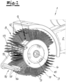
- the figures show a rotary brush tool which is equipped with a machine housing 1 and a drive unit 2 for a brush unit 3, which is only indicated and accommodated therein.
- the brush unit 3 has a ring brush 4, 5, which is located in the Embodiment and not limited to, it consists of a brush band 4 and bristles 5 connected to it and projecting outwards.
- the bristles 5 extend radially in relation to a rotation axis 6 and are essentially perpendicular to a surface of the ring brush 4, 5 or a surface of the brush belt 4.
- the bristles 5 are U-shaped bristles 5 made of steel, which are inserted into and pushed through the only indicated receiving holes 7 in the brush belt 4, as can be seen in the section of the Fig.1 can be understood.
- the bristles 5 form a bristle ring 8 with interruptions 9.
- the ring brush 4, 5 is driven in rotation by means of the drive unit 2 and is carried by a brush holder 10, 11.
- the brush holder 10, 11 is composed of a ring 10 and an insert 11 that can be inserted into it and carries the brush band 4 with the bristles 5.
- a brush holder 10, 11 may be used here, as shown in the EP 1 834 733 B1 is described in detail.
- the brush holder 10, 11 is each equipped with axial webs 12, which overlap the ring brush 4, 5 or the brush belt 4 in the area of the interruptions 9.
- the brush holder 10, 11 as a whole ensures a secure hold of the ring brush 4, 5 on a drive pin 13 of the drive unit 2 of the rotary brush tool, with the help of which the brush unit 3 is set in rotation, which according to the embodiment leads to a Figures 1 and 2 indicated counterclockwise movement around the rotation axis 6.
- the stop means 14 is a cylindrical pin 14 which is connected to the machine housing 1 of the rotary brush tool via an extension arm 15.
- the stop means 14 or the pin 14 is connected to the extension arm 15 parallel to the drive pin 13 of the drive unit 2 or parallel to the axis of rotation 6.
- the length of the stop means 14 is selected such that it essentially corresponds to the width of the brush belt 4, and consequently the stop means 14 does not protrude axially or only protrudes insignificantly in comparison to the ring brush 4, 5.
- the stop means 14 is non-circular in cross-section and rotates about its longitudinal axis 16.
- the non-circular design of the stop means or pin 14 according to the embodiment is realized and implemented in such a way that the stop means 14 is equipped with at least one longitudinal web 17 on its circumference.
- the stop means 14 is equipped with at least one longitudinal web 17 on its circumference.
- several longitudinal webs 17 are provided, distributed over the circumference of the stop means 14.
- the longitudinal webs 17 are generally arranged at the same angular distance over the circumference of the stop means 14.
- the respective longitudinal web 17 is triangular in cross section.
- the design within the scope of the embodiment according to the Fig.1 such that the respective longitudinal web 17 at this point runs in the longitudinal direction of the stop means 14 and consequently along the longitudinal axis 16.
- the design is such that the respective longitudinal web 17 runs spirally in comparison to the longitudinal direction of the stop means 14 and consequently its longitudinal axis 16.
- the stopping means 14 is designed to be rotatable about its longitudinal axis 16 within the scope of the invention.
- the stopping means 14 has a drive 18 which is in the Fig.1 is merely indicated.
- the design can be such that the stop means 14 is driven via the drive or the drive unit 2 inside the machine housing 1, specifically according to the invention in a circumferential direction of rotation opposite to the direction of rotation of the ring brush 4, 5. This applies explicitly to the contact area of the bristles 5 with the stop means 14. According to the embodiment, this means that both the ring brush 4, 5 and the stop means 14 rotate anti-clockwise.
- the ring brush 4, 5 meets the circumference of the stop means 14 with its bristles 5 on the circumference and both rotate anti-clockwise, an opposite movement is present on the circumference.
- the individual bristles 5 are not only slowed down when they hit the stop means 14 as in the prior art, but also experience an additional backward bending due to the additionally provided longitudinal webs 17, ie against the rotation of the ring brush 4, so that the bristles 5 hitting the respective longitudinal webs 17 hit a surface of a workpiece to be machined with increased kinetic energy, as already explained in the introduction.
- the drive 18 can be designed depending on the drive or the drive unit 2 of the brush holder 10, 11 with the ring brush 4, 5.
- the drive movement of the stop means 14 is derived from that of the drive unit 2.
- the drive unit 2 can be controlled via, for example, a Toothed belts or a gear work in a corresponding sense on the stop means 14.
- the drive 18 of the stop means 14 is designed independently of the drive or drive unit 2 of the brush holder 10, 11. Either way, the stop means 14 is driven in rotations about its longitudinal axis 16.
- the peripheral speed of the stop means 14 is generally designed to be equal to or higher than the peripheral speed of the ring brush 4, 5. In this way, the surface of the workpiece (not shown) is not only provided with an increased roughness in comparison to the prior art, but a more uniform surface finish is also achieved. This is where the main advantages can be seen.
Landscapes
- Engineering & Computer Science (AREA)
- Mechanical Engineering (AREA)
- Brushes (AREA)
- Finish Polishing, Edge Sharpening, And Grinding By Specific Grinding Devices (AREA)
- Polishing Bodies And Polishing Tools (AREA)
- Motor Or Generator Current Collectors (AREA)
- Turbine Rotor Nozzle Sealing (AREA)
- Pens And Brushes (AREA)
Priority Applications (10)
| Application Number | Priority Date | Filing Date | Title |
|---|---|---|---|
| PL22160267.5T PL4238451T3 (pl) | 2022-03-04 | 2022-03-04 | Zespół szczotki |
| EP22160267.5A EP4238451B1 (de) | 2022-03-04 | 2022-03-04 | Bürstenaggregat |
| JP2023028512A JP2023129322A (ja) | 2022-03-04 | 2023-02-27 | ブラシユニット |
| AU2023201270A AU2023201270A1 (en) | 2022-03-04 | 2023-03-01 | Brush assembly |
| KR1020230027984A KR20230131135A (ko) | 2022-03-04 | 2023-03-02 | 브러시 어셈블리 |
| MX2023002677A MX2023002677A (es) | 2022-03-04 | 2023-03-03 | Conjunto de cepillo. |
| TW112107755A TW202348345A (zh) | 2022-03-04 | 2023-03-03 | 刷具總成 |
| CN202310204338.8A CN116687119A (zh) | 2022-03-04 | 2023-03-03 | 刷组件 |
| CA3191762A CA3191762A1 (en) | 2022-03-04 | 2023-03-03 | Brush assembly |
| US18/117,447 US12453407B2 (en) | 2022-03-04 | 2023-03-05 | Brush assembly |
Applications Claiming Priority (1)
| Application Number | Priority Date | Filing Date | Title |
|---|---|---|---|
| EP22160267.5A EP4238451B1 (de) | 2022-03-04 | 2022-03-04 | Bürstenaggregat |
Publications (3)
| Publication Number | Publication Date |
|---|---|
| EP4238451A1 EP4238451A1 (de) | 2023-09-06 |
| EP4238451B1 true EP4238451B1 (de) | 2024-06-26 |
| EP4238451C0 EP4238451C0 (de) | 2024-06-26 |
Family
ID=80628491
Family Applications (1)
| Application Number | Title | Priority Date | Filing Date |
|---|---|---|---|
| EP22160267.5A Active EP4238451B1 (de) | 2022-03-04 | 2022-03-04 | Bürstenaggregat |
Country Status (10)
| Country | Link |
|---|---|
| US (1) | US12453407B2 (https=) |
| EP (1) | EP4238451B1 (https=) |
| JP (1) | JP2023129322A (https=) |
| KR (1) | KR20230131135A (https=) |
| CN (1) | CN116687119A (https=) |
| AU (1) | AU2023201270A1 (https=) |
| CA (1) | CA3191762A1 (https=) |
| MX (1) | MX2023002677A (https=) |
| PL (1) | PL4238451T3 (https=) |
| TW (1) | TW202348345A (https=) |
Families Citing this family (4)
| Publication number | Priority date | Publication date | Assignee | Title |
|---|---|---|---|---|
| EP4219073A1 (de) * | 2022-01-26 | 2023-08-02 | Monti-Werkzeuge GmbH | Rotativ antreibbare drehwerkzeugeinrichtung |
| DE102023126701A1 (de) | 2023-09-29 | 2025-04-03 | M O N T I - Werkzeuge GmbH | Rotationsbürstenwerkzeug |
| WO2025233848A1 (en) * | 2024-05-07 | 2025-11-13 | Toscana Spazzole Industriali S.R.L. | Roller and textile finishing device |
| CN119188447B (zh) * | 2024-11-29 | 2025-03-07 | 张家港市阿尔泰钢管制造有限公司 | 一种钢管加工用智能打磨装置 |
Family Cites Families (9)
| Publication number | Priority date | Publication date | Assignee | Title |
|---|---|---|---|---|
| US2178491A (en) * | 1939-04-03 | 1939-10-31 | John J Palotce | Bearing hone |
| SE405200B (sv) * | 1977-04-29 | 1978-11-27 | Electrolux Ab | Valsborste for dammsugare |
| DE102004021188A1 (de) * | 2004-04-29 | 2005-12-29 | Monti-Werkzeuge Gmbh | Bürstenaggregat |
| ATE405376T1 (de) * | 2006-03-13 | 2008-09-15 | Monti Werkzeuge Gmbh | Bürstenaggregat sowie verfahren zur bearbeitung einer werkstückoberfläche mit hilfe des bürstenaggregates |
| DE102010046398A1 (de) * | 2010-09-24 | 2012-03-29 | Monti-Werkzeuge Gmbh | Bürstenaggregat |
| KR101944574B1 (ko) * | 2011-10-26 | 2019-01-31 | 악티에볼라겟 엘렉트로룩스 | 진공 청소기용 청소 노즐 |
| CN104703526B (zh) * | 2012-12-21 | 2018-01-30 | 伊莱克斯公司 | 用于真空吸尘器的可旋转构件的清洁设备、吸尘器吸嘴、真空吸尘器以及清洁单元 |
| DE102018128269A1 (de) * | 2018-11-12 | 2020-05-14 | Monti-Werkzeuge Gmbh | Verfahren zur Bearbeitung einer Oberfläche eines Werkstückes |
| DE102019104621A1 (de) * | 2019-02-22 | 2020-08-27 | Monti-Werkzeuge Gmbh | Bürstenaggregat |
-
2022
- 2022-03-04 PL PL22160267.5T patent/PL4238451T3/pl unknown
- 2022-03-04 EP EP22160267.5A patent/EP4238451B1/de active Active
-
2023
- 2023-02-27 JP JP2023028512A patent/JP2023129322A/ja active Pending
- 2023-03-01 AU AU2023201270A patent/AU2023201270A1/en active Pending
- 2023-03-02 KR KR1020230027984A patent/KR20230131135A/ko active Pending
- 2023-03-03 CA CA3191762A patent/CA3191762A1/en active Pending
- 2023-03-03 CN CN202310204338.8A patent/CN116687119A/zh active Pending
- 2023-03-03 TW TW112107755A patent/TW202348345A/zh unknown
- 2023-03-03 MX MX2023002677A patent/MX2023002677A/es unknown
- 2023-03-05 US US18/117,447 patent/US12453407B2/en active Active
Also Published As
| Publication number | Publication date |
|---|---|
| CA3191762A1 (en) | 2023-09-04 |
| US20230276932A1 (en) | 2023-09-07 |
| PL4238451T3 (pl) | 2024-11-04 |
| CN116687119A (zh) | 2023-09-05 |
| AU2023201270A1 (en) | 2023-09-21 |
| MX2023002677A (es) | 2023-09-05 |
| JP2023129322A (ja) | 2023-09-14 |
| US12453407B2 (en) | 2025-10-28 |
| KR20230131135A (ko) | 2023-09-12 |
| EP4238451C0 (de) | 2024-06-26 |
| EP4238451A1 (de) | 2023-09-06 |
| TW202348345A (zh) | 2023-12-16 |
Similar Documents
| Publication | Publication Date | Title |
|---|---|---|
| EP4238451B1 (de) | Bürstenaggregat | |
| EP3019294B1 (de) | Verfahren zum bearbeiten einer lauffläche eines zylinders eines verbrennungsmotors | |
| EP3608504A1 (de) | Meissel mit einem stützelement mit einem zentrieransatz | |
| DE60214957T2 (de) | Verfahren zum Befestigen einer Hülse auf einer Welle und Hülsenvorrichtung für solch eine Befestigung | |
| EP0907458B2 (de) | Verfahren und vorrichtung zur herstellung von der kreisform abweichenden innen- und/oder aussenkonturen | |
| DE19526686A1 (de) | Mehrstufenbohrer | |
| DE10338682B4 (de) | Vorrichtung zum Bearbeiten von im wesentlichen flachen Werkstücken | |
| WO2005046015A1 (de) | Abisoliervorrichtung | |
| EP4218494B1 (de) | Bürstenaggregat | |
| EP2836630B1 (de) | Abtragwalze | |
| DE102019104621A1 (de) | Bürstenaggregat | |
| DE3727103A1 (de) | Werkzeug zum entgraten des uebergangs zwischen zwei bohrungen | |
| DE4212238A1 (de) | Verfahren zum Herstellen von Werkstücken, die auf einer Umfangsfläche mit Ausnehmungen versehen sind, und Vorrichtung zur Durchführung des Verfahrens | |
| EP3528987B1 (de) | Verfahren und vorrichtung zum bearbeiten von kugelbahnen und führungsstegen eines gelenkinnenteils | |
| EP3641983B1 (de) | Rundschalttisch mit kraft-optimiertem antrieb | |
| DE8912970U1 (de) | Käfigring zur Führung der Wälzkörper im Wälzlager | |
| EP3093089A1 (de) | Rotationswerkzeug | |
| EP1844901B1 (de) | Befestigungssystem und Befestigungsadapter | |
| DE69703343T2 (de) | Vorrichtung zum richten von draht | |
| DE102017105111B4 (de) | Entgratwerkzeug | |
| WO2017076833A1 (de) | Anfaswerkzeug mit führung zur schwingungs-eliminierung | |
| DE102020104692A1 (de) | Spitzenloses schleifen durch aufbringen einer spiralförmigen windung auf axiale nuten | |
| DE19646124C1 (de) | Spannvorrichtung für ringförmige Werkstückpakete | |
| EP3328600B1 (de) | Werkzeugmaschinentrennvorrichtung | |
| DE2166640C2 (de) | Verfahren zum Steuern der Draht-Vorschubgeschwindigkeit von Planetenrollengetrieben für Lichtbogenschweißmaschinen und Vorrichtung zur Durchführung des Verfahrens |
Legal Events
| Date | Code | Title | Description |
|---|---|---|---|
| PUAI | Public reference made under article 153(3) epc to a published international application that has entered the european phase |
Free format text: ORIGINAL CODE: 0009012 |
|
| STAA | Information on the status of an ep patent application or granted ep patent |
Free format text: STATUS: THE APPLICATION HAS BEEN PUBLISHED |
|
| AK | Designated contracting states |
Kind code of ref document: A1 Designated state(s): AL AT BE BG CH CY CZ DE DK EE ES FI FR GB GR HR HU IE IS IT LI LT LU LV MC MK MT NL NO PL PT RO RS SE SI SK SM TR |
|
| STAA | Information on the status of an ep patent application or granted ep patent |
Free format text: STATUS: REQUEST FOR EXAMINATION WAS MADE |
|
| 17P | Request for examination filed |
Effective date: 20240104 |
|
| RBV | Designated contracting states (corrected) |
Designated state(s): AL AT BE BG CH CY CZ DE DK EE ES FI FR GB GR HR HU IE IS IT LI LT LU LV MC MK MT NL NO PL PT RO RS SE SI SK SM TR |
|
| GRAP | Despatch of communication of intention to grant a patent |
Free format text: ORIGINAL CODE: EPIDOSNIGR1 |
|
| STAA | Information on the status of an ep patent application or granted ep patent |
Free format text: STATUS: GRANT OF PATENT IS INTENDED |
|
| GRAS | Grant fee paid |
Free format text: ORIGINAL CODE: EPIDOSNIGR3 |
|
| RIC1 | Information provided on ipc code assigned before grant |
Ipc: B24D 13/10 20060101ALI20240127BHEP Ipc: B24B 47/26 20060101ALI20240127BHEP Ipc: B24B 29/00 20060101ALI20240127BHEP Ipc: A46B 13/00 20060101AFI20240127BHEP |
|
| INTG | Intention to grant announced |
Effective date: 20240213 |
|
| GRAA | (expected) grant |
Free format text: ORIGINAL CODE: 0009210 |
|
| STAA | Information on the status of an ep patent application or granted ep patent |
Free format text: STATUS: THE PATENT HAS BEEN GRANTED |
|
| AK | Designated contracting states |
Kind code of ref document: B1 Designated state(s): AL AT BE BG CH CY CZ DE DK EE ES FI FR GB GR HR HU IE IS IT LI LT LU LV MC MK MT NL NO PL PT RO RS SE SI SK SM TR |
|
| REG | Reference to a national code |
Ref country code: GB Ref legal event code: FG4D Free format text: NOT ENGLISH |
|
| REG | Reference to a national code |
Ref country code: CH Ref legal event code: EP |
|
| REG | Reference to a national code |
Ref country code: DE Ref legal event code: R096 Ref document number: 502022001098 Country of ref document: DE |
|
| U01 | Request for unitary effect filed |
Effective date: 20240717 |
|
| U07 | Unitary effect registered |
Designated state(s): AT BE BG DE DK EE FI FR IT LT LU LV MT NL PT SE SI Effective date: 20240730 |
|
| PG25 | Lapsed in a contracting state [announced via postgrant information from national office to epo] |
Ref country code: HR Free format text: LAPSE BECAUSE OF FAILURE TO SUBMIT A TRANSLATION OF THE DESCRIPTION OR TO PAY THE FEE WITHIN THE PRESCRIBED TIME-LIMIT Effective date: 20240626 |
|
| PG25 | Lapsed in a contracting state [announced via postgrant information from national office to epo] |
Ref country code: GR Free format text: LAPSE BECAUSE OF FAILURE TO SUBMIT A TRANSLATION OF THE DESCRIPTION OR TO PAY THE FEE WITHIN THE PRESCRIBED TIME-LIMIT Effective date: 20240927 |
|
| PG25 | Lapsed in a contracting state [announced via postgrant information from national office to epo] |
Ref country code: HR Free format text: LAPSE BECAUSE OF FAILURE TO SUBMIT A TRANSLATION OF THE DESCRIPTION OR TO PAY THE FEE WITHIN THE PRESCRIBED TIME-LIMIT Effective date: 20240626 Ref country code: GR Free format text: LAPSE BECAUSE OF FAILURE TO SUBMIT A TRANSLATION OF THE DESCRIPTION OR TO PAY THE FEE WITHIN THE PRESCRIBED TIME-LIMIT Effective date: 20240927 Ref country code: RS Free format text: LAPSE BECAUSE OF FAILURE TO SUBMIT A TRANSLATION OF THE DESCRIPTION OR TO PAY THE FEE WITHIN THE PRESCRIBED TIME-LIMIT Effective date: 20240926 |
|
| PG25 | Lapsed in a contracting state [announced via postgrant information from national office to epo] |
Ref country code: IS Free format text: LAPSE BECAUSE OF FAILURE TO SUBMIT A TRANSLATION OF THE DESCRIPTION OR TO PAY THE FEE WITHIN THE PRESCRIBED TIME-LIMIT Effective date: 20241026 |
|
| PG25 | Lapsed in a contracting state [announced via postgrant information from national office to epo] |
Ref country code: CZ Free format text: LAPSE BECAUSE OF FAILURE TO SUBMIT A TRANSLATION OF THE DESCRIPTION OR TO PAY THE FEE WITHIN THE PRESCRIBED TIME-LIMIT Effective date: 20240626 |
|
| PG25 | Lapsed in a contracting state [announced via postgrant information from national office to epo] |
Ref country code: RO Free format text: LAPSE BECAUSE OF FAILURE TO SUBMIT A TRANSLATION OF THE DESCRIPTION OR TO PAY THE FEE WITHIN THE PRESCRIBED TIME-LIMIT Effective date: 20240626 Ref country code: SK Free format text: LAPSE BECAUSE OF FAILURE TO SUBMIT A TRANSLATION OF THE DESCRIPTION OR TO PAY THE FEE WITHIN THE PRESCRIBED TIME-LIMIT Effective date: 20240626 |
|
| PG25 | Lapsed in a contracting state [announced via postgrant information from national office to epo] |
Ref country code: SM Free format text: LAPSE BECAUSE OF FAILURE TO SUBMIT A TRANSLATION OF THE DESCRIPTION OR TO PAY THE FEE WITHIN THE PRESCRIBED TIME-LIMIT Effective date: 20240626 Ref country code: ES Free format text: LAPSE BECAUSE OF FAILURE TO SUBMIT A TRANSLATION OF THE DESCRIPTION OR TO PAY THE FEE WITHIN THE PRESCRIBED TIME-LIMIT Effective date: 20240626 |
|
| PG25 | Lapsed in a contracting state [announced via postgrant information from national office to epo] |
Ref country code: SM Free format text: LAPSE BECAUSE OF FAILURE TO SUBMIT A TRANSLATION OF THE DESCRIPTION OR TO PAY THE FEE WITHIN THE PRESCRIBED TIME-LIMIT Effective date: 20240626 Ref country code: SK Free format text: LAPSE BECAUSE OF FAILURE TO SUBMIT A TRANSLATION OF THE DESCRIPTION OR TO PAY THE FEE WITHIN THE PRESCRIBED TIME-LIMIT Effective date: 20240626 Ref country code: RO Free format text: LAPSE BECAUSE OF FAILURE TO SUBMIT A TRANSLATION OF THE DESCRIPTION OR TO PAY THE FEE WITHIN THE PRESCRIBED TIME-LIMIT Effective date: 20240626 Ref country code: IS Free format text: LAPSE BECAUSE OF FAILURE TO SUBMIT A TRANSLATION OF THE DESCRIPTION OR TO PAY THE FEE WITHIN THE PRESCRIBED TIME-LIMIT Effective date: 20241026 Ref country code: ES Free format text: LAPSE BECAUSE OF FAILURE TO SUBMIT A TRANSLATION OF THE DESCRIPTION OR TO PAY THE FEE WITHIN THE PRESCRIBED TIME-LIMIT Effective date: 20240626 Ref country code: CZ Free format text: LAPSE BECAUSE OF FAILURE TO SUBMIT A TRANSLATION OF THE DESCRIPTION OR TO PAY THE FEE WITHIN THE PRESCRIBED TIME-LIMIT Effective date: 20240626 |
|
| U20 | Renewal fee for the european patent with unitary effect paid |
Year of fee payment: 4 Effective date: 20250212 |
|
| PGFP | Annual fee paid to national office [announced via postgrant information from national office to epo] |
Ref country code: PL Payment date: 20250221 Year of fee payment: 4 |
|
| PLBE | No opposition filed within time limit |
Free format text: ORIGINAL CODE: 0009261 |
|
| STAA | Information on the status of an ep patent application or granted ep patent |
Free format text: STATUS: NO OPPOSITION FILED WITHIN TIME LIMIT |
|
| 26N | No opposition filed |
Effective date: 20250327 |
|
| PGFP | Annual fee paid to national office [announced via postgrant information from national office to epo] |
Ref country code: CH Payment date: 20250401 Year of fee payment: 4 |
|
| PG25 | Lapsed in a contracting state [announced via postgrant information from national office to epo] |
Ref country code: MC Free format text: LAPSE BECAUSE OF FAILURE TO SUBMIT A TRANSLATION OF THE DESCRIPTION OR TO PAY THE FEE WITHIN THE PRESCRIBED TIME-LIMIT Effective date: 20240626 |
|
| PG25 | Lapsed in a contracting state [announced via postgrant information from national office to epo] |
Ref country code: IE Free format text: LAPSE BECAUSE OF NON-PAYMENT OF DUE FEES Effective date: 20250304 |
|
| REG | Reference to a national code |
Ref country code: CH Ref legal event code: U11 Free format text: ST27 STATUS EVENT CODE: U-0-0-U10-U11 (AS PROVIDED BY THE NATIONAL OFFICE) Effective date: 20260401 |
|
| PGFP | Annual fee paid to national office [announced via postgrant information from national office to epo] |
Ref country code: GB Payment date: 20260324 Year of fee payment: 5 |
|
| PGFP | Annual fee paid to national office [announced via postgrant information from national office to epo] |
Ref country code: NO Payment date: 20260323 Year of fee payment: 5 |
|
| PGFP | Annual fee paid to national office [announced via postgrant information from national office to epo] |
Ref country code: TR Payment date: 20260226 Year of fee payment: 5 |
|
| U20 | Renewal fee for the european patent with unitary effect paid |
Year of fee payment: 5 Effective date: 20260318 |