EP4238441B1 - Sicherer halt-seneturon - Google Patents
Sicherer halt-seneturon Download PDFInfo
- Publication number
- EP4238441B1 EP4238441B1 EP23159475.5A EP23159475A EP4238441B1 EP 4238441 B1 EP4238441 B1 EP 4238441B1 EP 23159475 A EP23159475 A EP 23159475A EP 4238441 B1 EP4238441 B1 EP 4238441B1
- Authority
- EP
- European Patent Office
- Prior art keywords
- strap
- end part
- belt
- closure device
- support
- Prior art date
- Legal status (The legal status is an assumption and is not a legal conclusion. Google has not performed a legal analysis and makes no representation as to the accuracy of the status listed.)
- Active
Links
Images


Classifications
-
- A—HUMAN NECESSITIES
- A41—WEARING APPAREL
- A41F—GARMENT FASTENINGS; SUSPENDERS
- A41F9/00—Belts, girdles, or waistbands for trousers or skirts
- A41F9/002—Free belts
-
- A—HUMAN NECESSITIES
- A41—WEARING APPAREL
- A41F—GARMENT FASTENINGS; SUSPENDERS
- A41F9/00—Belts, girdles, or waistbands for trousers or skirts
- A41F9/02—Expansible or adjustable belts or girdles ; Adjustable fasteners comprising a track and a slide member
- A41F9/025—Adjustable belts or girdles
-
- A—HUMAN NECESSITIES
- A44—HABERDASHERY; JEWELLERY
- A44B—BUTTONS, PINS, BUCKLES, SLIDE FASTENERS, OR THE LIKE
- A44B11/00—Buckles; Similar fasteners for interconnecting straps or the like, e.g. for safety belts
- A44B11/20—Buckles; Similar fasteners for interconnecting straps or the like, e.g. for safety belts engaging holes or the like in strap
- A44B11/22—Buckle with fixed prong
- A44B11/223—Buckle with fixed prong fixed on a movable element
-
- A—HUMAN NECESSITIES
- A44—HABERDASHERY; JEWELLERY
- A44B—BUTTONS, PINS, BUCKLES, SLIDE FASTENERS, OR THE LIKE
- A44B11/00—Buckles; Similar fasteners for interconnecting straps or the like, e.g. for safety belts
- A44B11/20—Buckles; Similar fasteners for interconnecting straps or the like, e.g. for safety belts engaging holes or the like in strap
- A44B11/22—Buckle with fixed prong
- A44B11/226—Buckle with fixed prong with cover plate
-
- A—HUMAN NECESSITIES
- A41—WEARING APPAREL
- A41D—OUTERWEAR; PROTECTIVE GARMENTS; ACCESSORIES
- A41D2200/00—Components of garments
- A41D2200/10—Belts
Definitions
- the present invention relates to a belt.
- Such a belt must be able to allow its user to carry equipment safely around the waist, including a handgun holster, for example during demonstrations or clashes.
- the belts comprise a closing device with a removable belt buckle, fixed in rotation relative to the strap, once assembled thereto and provided with hooks on a first end part of the strap and a plate comprising orifices cooperating with the hooks on a second part extreme of the strap.
- a closing device is particularly effective in preventing any tearing of the belt and allows equipment to be attached on either side of the closing device.
- An aim of the invention is to overcome these drawbacks by proposing a belt comprising a closing device, easy to adjust while being difficult to open and/or to grasp by a third person and allowing equipment to be worn on both sides of the closing device as close as possible to the closing device.
- the invention relates to a belt according to claim 1.
- Such a belt allows for simplified adjustment around the waist so that it can be installed quickly while leaving the equipment or equipment supports in place.
- accessories can be easily attached to both sides of the closure device without being hindered by the free end since the latter extends from the inside of the belt.
- the belt allows for secure tightening around the user's waist. Indeed, in the tightened position, the free end is held in position between the user's waist and the strap, which prevents the free end from being grabbed by a third party with malicious intent.
- the belt according to the invention may comprise one or more characteristics according to claims 2 to 6, taken in isolation or in any technically possible combination.
- the invention also relates to a method of adjusting and tightening a belt according to claim 7.
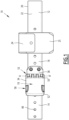
- FIG. 1 illustrates a belt 10 for law enforcement or security agents for example.
- the belt 10 comprises a strap 12 provided with a first end portion 14 and a second end portion 16 and a closing device 18 capable of fixing the first end portion 14 of the strap 12 with the second end portion 16 of the strap 12.
- the strap 12 is intended to come around the user's waist, over a belt for example.
- the strap 12 defines an internal face 20 and an external face 22 opposite the internal face 20.
- the internal face 20 is intended to be turned towards the body of a user, and more particularly towards the waist of the latter.
- the inner face 20 is intended to come against a belt or clothing of the user.
- the external face 22 is intended to be turned outwards, in particular away from the user's body.
- the strap 12 is intended to receive equipment supports 24, such as weapon cases, handcuff cases, baton holders, etc.
- the belt 10 may comprise at least one equipment support 24.
- the support 24 comprises at least one retaining element 25 for an item of equipment, the retaining element 25 extending over the external face 22 of the strap 12.
- the supports 24 are for example produced in the form of loops engaged around the strap 12 and comprising at least one retaining element 25 for a piece of equipment, in particular which extends over the external face 22 of the strap 12.
- the strap 12 is advantageously made of a material that is both flexible and strong, capable of withstanding the weight of the equipment or an attempt to tear it off by a third party.
- the strap 12 is, for example, made of leather or other material.
- the closing device 18 is movable between a clamping position illustrated in the figures 1 And 2 and an adjustment position illustrated on the Figure 3 .
- the first end part 14 can slide along the second end part 16 of the strap 12.
- the first end portion 14 is introduced into the closure device 18 through an entry loop 26, then through an exit loop 28, thus defining a free end 30 of the first end portion 14 extending in projection from the closure device 18 on the side of the exit loop 28, as illustrated in the Figure 2 .
- Adjusting the length of the free end 30 allows the tightness of the belt 10 to be adjusted around the user's waist.
- the closing device 18 is arranged to guide the free end 30 of the first end part 14 against the internal face 20 of the strap 12.
- the exit loop 28 is preferably open on the side of the internal face 20 of the strap 12 and closed on the side of the external face 22 of the strap 12.
- the cover 34 is rotatable relative to the support 32 between the adjustment position ( Fig 3 ) and the clamping position ( Figs. 1 And 2 ) along an axis of rotation A-A'.
- the cover 34 comprises an internal face 48 located opposite the support 32 and an external face 49 opposite the internal face 48.
- the internal face 20 of the first end part 14 of the strap 12 introduced into the housing 56 extends against the external face 42 of the support 32.
- the internal face 20 of the first end part 14 of the strap 12 extends between the external face 42 of the support 32 and the internal face 48 of the cover 34.
- the fixing plate 36 is advantageously secured to at least one of the support 32 and the cover 34.
- the closing device 18 further comprises a locking element 58 capable of locking the cover 34 in the clamping position.
- the closing device 18 further comprises at least one pin 64 intended to cooperate with at least one opening 66 provided in the first end part 14 of the strap 12 so as to fix the first end part 14 of the strap 12 to the second end part 16.
- the first end portion 14 of the strap 12 comprises a plurality of openings 66 spaced from each other in a longitudinal row extending along the length of the strap 12.
- the pin 64 is preferably accessible so that the user can insert the pin 64 into one of the openings 66 provided in the first end part 14 of the strap 12.
- pawn 64 includes a foot and a head with a diameter larger than the diameter of the foot.
- Pin 64 is for example of the “cartridge button” type.
- pawn 64 is a hook.
- the pin 64 is fixed on the support 32, for example by screwing or gluing.
- the support 32 and the pin 64 are made of a single piece and are, for example, manufactured by plastic injection.
- the cover 34 comprises a slot 68 for receiving the pin suitable for housing at least part of the pin 64, for example the head of the pin 64, when the closing device 18 is in the clamping position.
- the pin 64 is fixed to the cover 34 and the support 32 comprises a slot 68 for receiving the pin 64.
- the closing device 18 is made of a metallic or plastic material, for example zinc alloy or polymer.
- the user moves the closing device 18 into the adjustment position.
- the user then moves the strap 12 around his waist.
- the user inserts the first end part 14 of the strap 12 into the closing device 18 in the adjustment position.
- the user passes the free end 30 of the first end part 14 through the entry loop 26 of the closing device 18 then through the exit loop 28.
- the exit loop 28 guides the free end 30 towards the internal face 20, and in particular against the internal face 20 of the second part 16 of the strap 12.
- the external face 22 of the free end 30 of the first end part 14 of the strap 12 is thus opposite the internal face 20 of the second end part 16 of the strap 12.
- the first end part 14 is thus for example housed in the housing 56 defined between the cover 34 and the support 32.
- the free end 30 of the first end portion 14 of the strap 12 is held in position between the user's waist and the second end portion 16 of the strap 12, which makes it possible to prevent the free end from being grasped by a third person with malicious intent.
Landscapes
- Engineering & Computer Science (AREA)
- Textile Engineering (AREA)
- Buckles (AREA)
- Clamps And Clips (AREA)
Claims (7)
- Gürtel (10), umfassend:- einen Riemen (12), der eine Innenfläche (20), die dem Körper eines Benutzers zugewandt ist, und eine Außenfläche (22) gegenüber der Innenfläche (20) definiert; und- eine Schließvorrichtung (18), die geeignet ist, um einen ersten Endabschnitt (14) des Riemens (12) mit einem zweiten Endabschnitt (16) des Riemens (12) zu befestigen, wobei die Schließvorrichtung (18) zwischen einer Klemmposition, in der der erste Endabschnitt (14) des Riemens fest mit dem zweiten Endabschnitt (16) verbunden ist, und einer Einstellposition, in der der erste Endabschnitt (14) entlang des zweiten Endabschnitts (16) gleiten kann, bewegbar ist,zwischen dem Träger (32) und der Abdeckung (34) definiert ist, diewobei die Schließvorrichtung (18) angeordnet ist, um ein freies Ende (30) des ersten Endabschnitts (14) des Riemens (12) gegen die Innenfläche (20) des Riemens (12) zu führen, wenn der erste Endabschnitt (14) in der Einstellposition in die Schließvorrichtung (18) eingeführt wird, sodass in der Klemmstellung die Außenfläche (22) des freien Endes (30) des ersten Endabschnitts (14) des Riemens an der Innenfläche (20) des zweiten Endabschnitts (16) des Riemens anliegt;wobei die Schließvorrichtung (18) eine Ausgangsschlaufe (28) definiert, wobei die Ausgangsschlaufe (28) an der Seite der Innenfläche (20) offen und an der Seite der Außenfläche (22) geschlossen ist, wenn die Schließvorrichtung (18) in der Einstellposition ist;die Schließvorrichtung (18) umfassend einen Träger (32) und eine Abdeckung (34), die in Bezug auf den Träger (32) zwischen der Einstellposition und der Spannposition drehbar ist; wobei der Gürtel dadurch gekennzeichnet ist, dassdie Ausgangsschlaufe (28)
Ausgangsschlaufe (28) auf der Innenseite durch eine Außenfläche (42) eines ersten seitlichen Rands (44) des Trägers (32) und auf der Außenseite durch ein Scharnier (53) begrenzt ist. - Gürtel (10) nach Anspruch 1, wobei die Schließvorrichtung (18) eine Befestigungsplatte (36) umfasst, die an dem zweiten Endabschnitt (16) des Riemens (12) befestigt ist.
- Gürtel (10) nach Anspruch 2, wobei die Befestigungsplatte (36) fest mit mindestens einem der Träger (32) und der Abdeckung (34) verbunden ist.
- Gürtel (10) nach einem der Ansprüche 1 bis 3, wobei die Schließvorrichtung (18) mindestens einen Stift (64) umfasst, der mit einer Öffnung (66) zusammenwirken soll, die in dem ersten Endabschnitt (14) des Riemens bereitgestellt ist, um den ersten Endabschnitt (14) des Riemens an dem zweiten Endabschnitt (16) zu befestigen.
- Gürtel (10) nach Anspruch 4, wobei mindestens ein Stift (64) an dem Träger (32) und/oder der Abdeckung (34) befestigt ist, wobei der Träger (32) und/oder die Abdeckung (34) einen Schlitz zum Aufnehmen des Stifts aufweist.
- Gürtel (10) nach einem der Ansprüche 1 bis 5, wobei die Schließvorrichtung (18) ein Verriegelungselement (58) umfasst, das geeignet ist, um die Abdeckung (34) in der Klemmposition zu verriegeln.
- Einstell- und Klemmverfahren eines Gürtels (10) nach einem der vorherigen Ansprüche, umfassend die folgenden Schritte:- Bringen der Schließvorrichtung (18) in Einstellposition;- Einführen des ersten Endabschnitts (14) des Riemens (12) in die Schließvorrichtung (18) in der Einstellposition und Einstellen der Länge des freien Endes (30) des ersten Endabschnitts (14) des Riemens (12), wobei die Außenfläche (22) des freien Endes (10) des ersten Endabschnitts (14) des Riemens (12) der Innenfläche (20) des zweiten Endabschnitts (16) des Riemens (12) gegenüberliegt; und- Bringen der Schließvorrichtung (18) von der Einstellposition in die Klemmposition, um den ersten Endabschnitt (14) an dem zweiten Endabschnitt (16) des Riemens (12) zu befestigen.
Applications Claiming Priority (1)
| Application Number | Priority Date | Filing Date | Title |
|---|---|---|---|
| FR2201857A FR3133117B1 (fr) | 2022-03-03 | 2022-03-03 | Ceinturon de tenue sécurisé |
Publications (3)
| Publication Number | Publication Date |
|---|---|
| EP4238441A1 EP4238441A1 (de) | 2023-09-06 |
| EP4238441B1 true EP4238441B1 (de) | 2025-06-25 |
| EP4238441C0 EP4238441C0 (de) | 2025-06-25 |
Family
ID=81928170
Family Applications (1)
| Application Number | Title | Priority Date | Filing Date |
|---|---|---|---|
| EP23159475.5A Active EP4238441B1 (de) | 2022-03-03 | 2023-03-01 | Sicherer halt-seneturon |
Country Status (3)
| Country | Link |
|---|---|
| EP (1) | EP4238441B1 (de) |
| ES (1) | ES3040346T3 (de) |
| FR (1) | FR3133117B1 (de) |
Family Cites Families (2)
| Publication number | Priority date | Publication date | Assignee | Title |
|---|---|---|---|---|
| KR860003015Y1 (ko) * | 1985-03-18 | 1986-11-06 | 주식회사호산상사 | 버 클 |
| US9155361B2 (en) * | 2011-02-28 | 2015-10-13 | Roland Iten Mechanical Luxury Sa | Mechanical lever buckle for belt and watch strap |
-
2022
- 2022-03-03 FR FR2201857A patent/FR3133117B1/fr active Active
-
2023
- 2023-03-01 EP EP23159475.5A patent/EP4238441B1/de active Active
- 2023-03-01 ES ES23159475T patent/ES3040346T3/es active Active
Also Published As
| Publication number | Publication date |
|---|---|
| FR3133117B1 (fr) | 2024-11-29 |
| ES3040346T3 (en) | 2025-10-30 |
| EP4238441A1 (de) | 2023-09-06 |
| FR3133117A1 (fr) | 2023-09-08 |
| EP4238441C0 (de) | 2025-06-25 |
Similar Documents
| Publication | Publication Date | Title |
|---|---|---|
| FR3054777B1 (fr) | Ceinturon de tenue securise | |
| US3879810A (en) | Pocketed spring buckle improvements | |
| FR2745612A1 (fr) | Systeme de pince de retenue | |
| FR2947701A1 (fr) | Sac a dos | |
| EP3470935B1 (de) | Einrastsystem, beispielsweise zum festmachen eines armbands an einer armbanduhr | |
| FR2825589A1 (fr) | Gant de protection ambidextre | |
| EP4238441B1 (de) | Sicherer halt-seneturon | |
| CA2921542C (fr) | Porte bidon | |
| EP2244048B1 (de) | Gewehrriemen | |
| EP0126382A1 (de) | Dehnbarer Verschluss für ein gelenkiges Armband, insbesondere ein Uhrarmband | |
| FR2550923A1 (fr) | Casque de protection avec un dispositif de reglage de jugulaire | |
| WO2006056664A1 (fr) | Dispositif anti-vol de bagage adaptable sur une ceinture de securite | |
| EP2134210B1 (de) | Trageband, z. b. für polizeidienstliches zubehör | |
| EP1875823A1 (de) | Schnallen mit zwei trennbaren Teilen zur Befestigung eines V-Gurts und ihre Benutzung zur Befestigung eines Schutzhelms | |
| FR2729274A1 (fr) | Gant de protection a sangle amovible | |
| FR2951818A1 (fr) | Adaptateur de ceinture | |
| CH716147B1 (fr) | Fermoir à boucle déployante. | |
| US11478066B2 (en) | Baton scabbard | |
| EP2189749B1 (de) | Gewehrriemen | |
| EP2875742B1 (de) | Schusssichere Schutzausrüstung, die seitliche Verschlussmittel umfasst | |
| FR2761149A1 (fr) | Dispositif orientable pour porter un etui a pistolet automatique a la taille d'une personne | |
| EP2271231B1 (de) | Armbanduhr | |
| CH696866A5 (fr) | Bracelet réglable notamment pour montre de plongée. | |
| FR2857636A1 (fr) | Dispositif anti-vol de bagages adaptable sur une ceinture de securite | |
| FR3073717A1 (fr) | Systeme d'attache de casque de protection |
Legal Events
| Date | Code | Title | Description |
|---|---|---|---|
| PUAI | Public reference made under article 153(3) epc to a published international application that has entered the european phase |
Free format text: ORIGINAL CODE: 0009012 |
|
| STAA | Information on the status of an ep patent application or granted ep patent |
Free format text: STATUS: THE APPLICATION HAS BEEN PUBLISHED |
|
| AK | Designated contracting states |
Kind code of ref document: A1 Designated state(s): AL AT BE BG CH CY CZ DE DK EE ES FI FR GB GR HR HU IE IS IT LI LT LU LV MC ME MK MT NL NO PL PT RO RS SE SI SK SM TR |
|
| STAA | Information on the status of an ep patent application or granted ep patent |
Free format text: STATUS: REQUEST FOR EXAMINATION WAS MADE |
|
| 17P | Request for examination filed |
Effective date: 20240215 |
|
| RBV | Designated contracting states (corrected) |
Designated state(s): AL AT BE BG CH CY CZ DE DK EE ES FI FR GB GR HR HU IE IS IT LI LT LU LV MC ME MK MT NL NO PL PT RO RS SE SI SK SM TR |
|
| GRAP | Despatch of communication of intention to grant a patent |
Free format text: ORIGINAL CODE: EPIDOSNIGR1 |
|
| STAA | Information on the status of an ep patent application or granted ep patent |
Free format text: STATUS: GRANT OF PATENT IS INTENDED |
|
| INTG | Intention to grant announced |
Effective date: 20250210 |
|
| GRAS | Grant fee paid |
Free format text: ORIGINAL CODE: EPIDOSNIGR3 |
|
| GRAA | (expected) grant |
Free format text: ORIGINAL CODE: 0009210 |
|
| STAA | Information on the status of an ep patent application or granted ep patent |
Free format text: STATUS: THE PATENT HAS BEEN GRANTED |
|
| AK | Designated contracting states |
Kind code of ref document: B1 Designated state(s): AL AT BE BG CH CY CZ DE DK EE ES FI FR GB GR HR HU IE IS IT LI LT LU LV MC ME MK MT NL NO PL PT RO RS SE SI SK SM TR |
|
| REG | Reference to a national code |
Ref country code: GB Ref legal event code: FG4D Free format text: NOT ENGLISH |
|
| REG | Reference to a national code |
Ref country code: CH Ref legal event code: EP |
|
| REG | Reference to a national code |
Ref country code: DE Ref legal event code: R096 Ref document number: 602023004177 Country of ref document: DE |
|
| REG | Reference to a national code |
Ref country code: CH Ref legal event code: EP |
|
| REG | Reference to a national code |
Ref country code: IE Ref legal event code: FG4D Free format text: LANGUAGE OF EP DOCUMENT: FRENCH |
|
| U01 | Request for unitary effect filed |
Effective date: 20250723 |
|
| U07 | Unitary effect registered |
Designated state(s): AT BE BG DE DK EE FI FR IT LT LU LV MT NL PT RO SE SI Effective date: 20250808 |
|
| PG25 | Lapsed in a contracting state [announced via postgrant information from national office to epo] |
Ref country code: NO Free format text: LAPSE BECAUSE OF FAILURE TO SUBMIT A TRANSLATION OF THE DESCRIPTION OR TO PAY THE FEE WITHIN THE PRESCRIBED TIME-LIMIT Effective date: 20250925 |
|
| PG25 | Lapsed in a contracting state [announced via postgrant information from national office to epo] |
Ref country code: HR Free format text: LAPSE BECAUSE OF FAILURE TO SUBMIT A TRANSLATION OF THE DESCRIPTION OR TO PAY THE FEE WITHIN THE PRESCRIBED TIME-LIMIT Effective date: 20250625 |
|
| PG25 | Lapsed in a contracting state [announced via postgrant information from national office to epo] |
Ref country code: RS Free format text: LAPSE BECAUSE OF FAILURE TO SUBMIT A TRANSLATION OF THE DESCRIPTION OR TO PAY THE FEE WITHIN THE PRESCRIBED TIME-LIMIT Effective date: 20250925 |
|
| REG | Reference to a national code |
Ref country code: ES Ref legal event code: FG2A Ref document number: 3040346 Country of ref document: ES Kind code of ref document: T3 Effective date: 20251030 |
|
| REG | Reference to a national code |
Ref country code: GR Ref legal event code: EP Ref document number: 20250401665 Country of ref document: GR Effective date: 20251009 |