EP4237159B1 - Verfahren und systeme zur verarbeitung von photopolymerisierbaren zusammensetzungen - Google Patents
Verfahren und systeme zur verarbeitung von photopolymerisierbaren zusammensetzungen Download PDFInfo
- Publication number
- EP4237159B1 EP4237159B1 EP21794634.2A EP21794634A EP4237159B1 EP 4237159 B1 EP4237159 B1 EP 4237159B1 EP 21794634 A EP21794634 A EP 21794634A EP 4237159 B1 EP4237159 B1 EP 4237159B1
- Authority
- EP
- European Patent Office
- Prior art keywords
- photopolymerizable composition
- sieve
- insert
- separated
- openings
- Prior art date
- Legal status (The legal status is an assumption and is not a legal conclusion. Google has not performed a legal analysis and makes no representation as to the accuracy of the status listed.)
- Active
Links
Images


Classifications
-
- B—PERFORMING OPERATIONS; TRANSPORTING
- B04—CENTRIFUGAL APPARATUS OR MACHINES FOR CARRYING-OUT PHYSICAL OR CHEMICAL PROCESSES
- B04B—CENTRIFUGES
- B04B5/00—Other centrifuges
- B04B5/04—Radial chamber apparatus for separating predominantly liquid mixtures, e.g. butyrometers
- B04B5/0407—Radial chamber apparatus for separating predominantly liquid mixtures, e.g. butyrometers for liquids contained in receptacles
- B04B5/0414—Radial chamber apparatus for separating predominantly liquid mixtures, e.g. butyrometers for liquids contained in receptacles comprising test tubes
- B04B5/0421—Radial chamber apparatus for separating predominantly liquid mixtures, e.g. butyrometers for liquids contained in receptacles comprising test tubes pivotably mounted
-
- B—PERFORMING OPERATIONS; TRANSPORTING
- B01—PHYSICAL OR CHEMICAL PROCESSES OR APPARATUS IN GENERAL
- B01D—SEPARATION
- B01D21/00—Separation of suspended solid particles from liquids by sedimentation
- B01D21/26—Separation of sediment aided by centrifugal force or centripetal force
- B01D21/262—Separation of sediment aided by centrifugal force or centripetal force by using a centrifuge
-
- B—PERFORMING OPERATIONS; TRANSPORTING
- B04—CENTRIFUGAL APPARATUS OR MACHINES FOR CARRYING-OUT PHYSICAL OR CHEMICAL PROCESSES
- B04B—CENTRIFUGES
- B04B7/00—Elements of centrifuges
- B04B7/08—Rotary bowls
- B04B7/18—Rotary bowls formed or coated with sieving or filtering elements
-
- B—PERFORMING OPERATIONS; TRANSPORTING
- B29—WORKING OF PLASTICS; WORKING OF SUBSTANCES IN A PLASTIC STATE IN GENERAL
- B29C—SHAPING OR JOINING OF PLASTICS; SHAPING OF MATERIAL IN A PLASTIC STATE, NOT OTHERWISE PROVIDED FOR; AFTER-TREATMENT OF THE SHAPED PRODUCTS, e.g. REPAIRING
- B29C64/00—Additive manufacturing, i.e. manufacturing of three-dimensional [3D] objects by additive deposition, additive agglomeration or additive layering, e.g. by 3D printing, stereolithography or selective laser sintering
- B29C64/10—Processes of additive manufacturing
- B29C64/106—Processes of additive manufacturing using only liquids or viscous materials, e.g. depositing a continuous bead of viscous material
- B29C64/124—Processes of additive manufacturing using only liquids or viscous materials, e.g. depositing a continuous bead of viscous material using layers of liquid which are selectively solidified
-
- B—PERFORMING OPERATIONS; TRANSPORTING
- B29—WORKING OF PLASTICS; WORKING OF SUBSTANCES IN A PLASTIC STATE IN GENERAL
- B29C—SHAPING OR JOINING OF PLASTICS; SHAPING OF MATERIAL IN A PLASTIC STATE, NOT OTHERWISE PROVIDED FOR; AFTER-TREATMENT OF THE SHAPED PRODUCTS, e.g. REPAIRING
- B29C64/00—Additive manufacturing, i.e. manufacturing of three-dimensional [3D] objects by additive deposition, additive agglomeration or additive layering, e.g. by 3D printing, stereolithography or selective laser sintering
- B29C64/30—Auxiliary operations or equipment
- B29C64/307—Handling of material to be used in additive manufacturing
- B29C64/314—Preparation
-
- B—PERFORMING OPERATIONS; TRANSPORTING
- B29—WORKING OF PLASTICS; WORKING OF SUBSTANCES IN A PLASTIC STATE IN GENERAL
- B29C—SHAPING OR JOINING OF PLASTICS; SHAPING OF MATERIAL IN A PLASTIC STATE, NOT OTHERWISE PROVIDED FOR; AFTER-TREATMENT OF THE SHAPED PRODUCTS, e.g. REPAIRING
- B29C64/00—Additive manufacturing, i.e. manufacturing of three-dimensional [3D] objects by additive deposition, additive agglomeration or additive layering, e.g. by 3D printing, stereolithography or selective laser sintering
- B29C64/30—Auxiliary operations or equipment
- B29C64/35—Cleaning
-
- B—PERFORMING OPERATIONS; TRANSPORTING
- B33—ADDITIVE MANUFACTURING TECHNOLOGY
- B33Y—ADDITIVE MANUFACTURING, i.e. MANUFACTURING OF THREE-DIMENSIONAL [3-D] OBJECTS BY ADDITIVE DEPOSITION, ADDITIVE AGGLOMERATION OR ADDITIVE LAYERING, e.g. BY 3-D PRINTING, STEREOLITHOGRAPHY OR SELECTIVE LASER SINTERING
- B33Y40/00—Auxiliary operations or equipment, e.g. for material handling
- B33Y40/20—Post-treatment, e.g. curing, coating or polishing
-
- B—PERFORMING OPERATIONS; TRANSPORTING
- B33—ADDITIVE MANUFACTURING TECHNOLOGY
- B33Y—ADDITIVE MANUFACTURING, i.e. MANUFACTURING OF THREE-DIMENSIONAL [3-D] OBJECTS BY ADDITIVE DEPOSITION, ADDITIVE AGGLOMERATION OR ADDITIVE LAYERING, e.g. BY 3-D PRINTING, STEREOLITHOGRAPHY OR SELECTIVE LASER SINTERING
- B33Y70/00—Materials specially adapted for additive manufacturing
-
- B—PERFORMING OPERATIONS; TRANSPORTING
- B04—CENTRIFUGAL APPARATUS OR MACHINES FOR CARRYING-OUT PHYSICAL OR CHEMICAL PROCESSES
- B04B—CENTRIFUGES
- B04B5/00—Other centrifuges
- B04B5/04—Radial chamber apparatus for separating predominantly liquid mixtures, e.g. butyrometers
- B04B5/0407—Radial chamber apparatus for separating predominantly liquid mixtures, e.g. butyrometers for liquids contained in receptacles
- B04B2005/0435—Radial chamber apparatus for separating predominantly liquid mixtures, e.g. butyrometers for liquids contained in receptacles with adapters for centrifuge tubes or bags
-
- B—PERFORMING OPERATIONS; TRANSPORTING
- B29—WORKING OF PLASTICS; WORKING OF SUBSTANCES IN A PLASTIC STATE IN GENERAL
- B29B—PREPARATION OR PRETREATMENT OF THE MATERIAL TO BE SHAPED; MAKING GRANULES OR PREFORMS; RECOVERY OF PLASTICS OR OTHER CONSTITUENTS OF WASTE MATERIAL CONTAINING PLASTICS
- B29B17/00—Recovery of plastics or other constituents of waste material containing plastics
- B29B17/02—Separating plastics from other materials
- B29B2017/0213—Specific separating techniques
- B29B2017/0217—Mechanical separating techniques; devices therefor
- B29B2017/0231—Centrifugating, cyclones
Definitions
- the present disclosure relates to processing photopolymerizable compositions to remove contaminants from the compositions and systems for processing the compositions, such as for use with additive manufacturing techniques.
- Photopolymerizable compositions have been employed in many industries, including using additive manufacturing techniques. Less than an entire volume of a photopolymerizable composition may be polymerized to form an article, yet the remaining photopolymerizable composition often contains one or more contaminants produced during polymerization processes.
- An example of a method and a system employed in processing photopolymerizable compositions is known form CN205871234U .
- a method in a first aspect, includes a) obtaining an insert comprising a sieve defining a plurality of openings each having a diameter of 10 to 200 micrometers; b) placing a volume of a fluid in the insert, wherein the fluid contains a photopolymerizable composition and a contaminant; and c) subjecting the volume of the fluid to a centrifugal force to separate the contaminant from at least a portion of the photopolymerizable composition by retaining the contaminant in the insert and passing at least a portion the photopolymerizable composition through the sieve of the insert to provide a separated photopolymerizable composition.
- a system in a second aspect, includes a) an additive manufacturing apparatus; b) a centrifuge; and c) an insert configured to be inserted in the centrifuge, the insert comprising a sieve defining a plurality of openings each having a diameter of 10 to 200 micrometers.
- the method and system may be useful for removing contaminant(s) from a photopolymerizable composition to decrease an amount of the photopolymerizable composition being discarded as waste material or reused while containing contaminant(s), leading to the production of lower quality three-dimensional objects.
- the cleaned photopolymerizable composition has sufficient cleanliness to be used in the same batch with a volume of unused (e.g., initial) photopolymerizable composition. Even compositions that have a viscous and/or pasty consistency may have contaminants successfully removed from them using methods or systems according to at least certain embodiments of the present disclosure.
- a three-dimensional object e.g., a printed part
- unintended undercuts in the printing geometries can result in tiny parts of resin that are cured without sufficient adhesion to the rest of a printed part and pollute the remaining photopolymerizable composition, the tiny parts having a size of one or more voxels.
- Another issue can be that after repeated use, one or more surfaces of a vat exhibit increased adhesion forces during the printing and entire parts or portions of a support geometry can break off and pollute the vat.
- Further pollution can be, e.g., lint from the surrounding air, although such pollution can be minimized by using, e.g., a laminar flow system for applying clean room conditions.
- contaminants of tiny broken parts, lint, etc. are impractical to completely prevent.
- a "monomer” is a single, one unit molecule capable of combination with itself or other monomers to form oligomers or polymers; an "oligomer” is a component having 2 to 9 repeat units; and a “polymer” is a component having 10 or more repeat units.
- alkyl means a linear or branched, cyclic or acyclic, saturated monovalent hydrocarbon having from one to thirty-two carbon atoms, e.g., methyl, ethyl, 1-propyl, 2-propyl, pentyl, and the like.
- alkylene means a linear saturated divalent hydrocarbon having from one to twelve carbon atoms or a branched saturated divalent hydrocarbon radical having from two to twelve carbon atoms, e.g., methylene, ethylene, propylene, 2-methylpropylene, pentylene, hexylene, and the like.
- aryl refers to a monovalent group that is a radical of an aromatic carbocyclic compound.
- the aryl group has at least one aromatic carbocyclic ring and can have 1 to 5 optional rings that are connected to or fused to the aromatic carbocyclic ring.
- the additional rings can be aromatic, aliphatic, or a combination thereof.
- the aryl group usually has 5 to 20 carbon atoms.
- substituted aryl refers to an aryl group substituted with at least one alkyl group, substituted with at least one alkoxy group, or substituted with at least one alkyl group plus at least one alkoxy group.
- the substituted aryl group contains 6 to 40 carbon atoms.
- the substituted aryl group often contains an aryl group having 5 to 20 carbon atoms and an alkyl group and/or alkoxy group each having 1 to 20 carbon atoms.
- (meth)acrylate-functional compounds are compounds that include, among other things, a (meth)acrylate moiety.
- diameter refers to the longest straight length across a shape (two-dimensional or three-dimensional) that intersects a center of the shape.
- fluid refers to emulsions, dispersions, suspensions, solutions, and pure components having a continuous liquid phase, and excludes powders and particulates in solid form.
- liquid refers to the state of matter that is not solid or gas, which has a definite volume and an indefinite shape.
- curing and “polymerizing” each mean the hardening or partial hardening of a composition by any mechanism, e.g., by heat, light, radiation, e-beam, microwave, chemical reaction, or combinations thereof.
- cured refers to a material or composition that has been hardened or partially hardened (e.g., polymerized or crosslinked) by one or more curing mechanisms.
- photopolymerizable refers to a composition containing at least one material that can be hardened or partially hardened using actinic radiation.
- initial photopolymerizable composition refers to a photopolymerizable composition that has not had any of its volume exposed to actinic radiation, which contains a full amount of each component of a formulation and lacks any contaminants formed during curing.
- separated photopolymerizable composition refers to a composition that contains at least one material that can be hardened or partially hardened using actinic radiation, containing less than a full amount of at least one component of a formulation.
- the separated photopolymerizable composition has had a portion of its volume exposed to actinic radiation.
- the separated photopolymerizable composition has also been subjected to a process to separate at least one contaminant from the photopolymerizable composition.
- Contaminant refers to a material disposed in a photopolymerizable composition that was not deliberately included in the composition formulation. Contaminants may include at least one of an oligomer, a polymer, a dust particle, lint, a plurality of cured voxels formed from the photopolymerizable composition, or a part formed of a polymerized product of the photopolymerizable composition.
- mass inertial force as referred to herein may be specified as force per unit mass and therefore may be specified in the unit m/s 2 . Further, the mass inertial force can be expressed by the G-force which is a factor of the acceleration of gravity. For the purposes of the present specification the acceleration of gravity is 9.81 m/s 2 . Consequently, for example a mass inertial force of 9.81 m/s 2 can be expressed as 1 G.
- the term "generally”, unless otherwise specifically defined, means that the property or attribute would be readily recognizable by a person of ordinary skill but without requiring absolute precision or a perfect match (e.g., within +/- 20 % for quantifiable properties).
- the term “substantially”, unless otherwise specifically defined, means to a high degree of approximation (e.g., within +/- 10% for quantifiable properties) but again without requiring absolute precision or a perfect match. Terms such as same, equal, uniform, constant, strictly, and the like, are understood to be within the usual tolerances or measuring error applicable to the particular circumstance rather than requiring absolute precision or a perfect match.
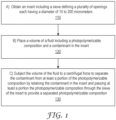
- the method comprises Step 110 to a) obtain an insert comprising a sieve defining a plurality of openings each having a diameter of 10 to 200 micrometers; and Step 120 to b) place a volume of a fluid in the insert, wherein the fluid comprises a photopolymerizable composition and a contaminant.
- the method further comprises Step 130 to c) subject the volume of the fluid to a centrifugal force to separate the contaminant from at least a portion of the photopolymerizable composition by retaining the contaminant in the insert and passing at least a portion the photopolymerizable composition through the sieve of the insert to provide a separated photopolymerizable composition.
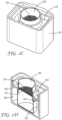
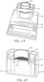
- FIG. 3B is a schematic perspective view of another exemplary insert disposed partially in a container.
- the outer dimensions of the insert 320 are sized to fit in a cup 360 and the cup 360 also acts as the container to receive separated photopolymerizable composition that passes through a sieve 340 of the insert 320.
- the embodiment illustrated in FIG. 3B is shown assembled ready for subjection to centrifugal force, for instance comprising the insert 320 supported by a stand 350, all disposed in a container/cup 360.
- the upper portion of the insert 320 is located above the top of the container/cup 360.
- the stand 350 of this embodiment includes an integral wall 355 that surrounds at least some of an exterior of the insert 320 and provides stability to the insert 320 within the container/cup 360.
- a schematic top view is provided of an exemplary sieve 440 having a plurality of openings 442, each having a star shape.
- the shape of the openings of the sieve is not particularly limited, and in some embodiments comprises one or more of a circular shape, an oval shape, a quadrilateral shape, a triangular shape, or a star shape.
- a suitable sieve is a woven material comprising quadrilateral (e.g., square or rectangle) openings.
- sieves according to the present disclosure define a plurality of openings each having a diameter of 10 to 200 micrometers.
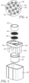
- a schematic perspective exploded view is provided of another exemplary insert 520 disposed partially in a container 530.
- the insert 520 is integrally formed with a stand 550 and the stand is sized to fit within a cup 560.
- a lower portion of a wall 522 of the insert may be configured to nest within an upper portion of a wall 532 of the container 530.
- Other configurations that provide an insert partially disposed within a container may be used.
- the upper portion of the insert 520 will be located above the top of the cup 560 when the components are assembled.
- the stand 550 of this embodiment includes a plurality (e.g., four) of legs 552 to support the insert 520 within the cup 560.
- the bulk of the uncured photopolymerizable composition e.g., remaining in an additive manufacturing vat
- the whole remaining contents of the vat may be subjected to centrifugal force to separate at least the part fragments from the photopolymerizable composition to enable continuing production of three-dimensional objects from the photopolymerizable composition.
- Some scenarios in which bulk recycling of a photopolymerizable composition would be useful include, for instance, when a print job fails and broken parts are present in the photopolymerizable composition, or following (e.g., continuous) printing of many parts.
- methods according to the present disclosure further comprise a step of i) analyzing the separated photopolymerizable composition for at least one of homogeneity or photoinitiator content.
- homogeneity is analyzed by at least one of measuring a density, measuring a color, or measuring a filler content of multiple samples of the separated photopolymerizable composition.
- homogeneity is analyzed by preparing three-dimensional objects from multiple samples of the separated photopolymerizable composition followed by testing of mechanical properties (e.g., tensile strength) and measuring the physical dimensions.
- test bars having a shape e.g., dogbone
- mechanical property standard test methods are formed, either by additive manufacturing samples of the separated photopolymerizable composition or by using a mold and casting samples of the separated photopolymerizable composition.
- Testing mechanical properties can indicate if photoinitiator concentration has decreased from the initial photopolymerizable composition or lack of homogeneity. If the physical dimensions of the objects are smaller or larger than designed, the separated photopolymerizable composition likely undercured or overcured, respectively, and does not meet homogeneity requirements.
- a photopolymerizable composition must be stable against significant separation of its components, at least on a time scale required to complete a print job.
- methods according to the present disclosure further comprise a step of j) placing at least a portion of the separated photopolymerizable composition into an additive manufacturing apparatus; and k) selectively curing the separated photopolymerizable composition in the additive manufacturing apparatus using actinic radiation to form a three-dimensional object. Additionally, in some embodiments, methods according to the present disclosure further comprise, prior to step j) or step k), a step of l) blending at least a portion of the separated photopolymerizable composition with a volume of an initial photopolymerizable composition.
- the separated photopolymerizable composition has sufficient cleanliness to be used by itself in place of, or in the same batch with, an unused (e.g., initial) photopolymerizable composition.
- processes may be used in a medical product process by enabling recycling within one batch and reusing the recycled photopolymerizable composition without actual material batch mixing.
- a photopolymerizable composition may have only come into direct contact with a few simple shaped manufactured parts, rendering the photopolymerizable composition readily recyclable by separation from the parts and any contaminants.
- methods according to the present disclosure further comprise a step of m) at least one of cleaning the sieve or replacing the sieve once the plurality of openings of the sieve are clogged by the contaminant.
- the sieve tends to become clogged by one or more contaminants, requiring washing or exchange for a clean sieve.
- a sieve is composed of nylon
- isopropanol is a suitable cleaning solvent for the sieve.
- disposable sieves may be employed that are discarded following use.
- a system comprising:
- Methods of printing a three-dimensional object described herein can include forming the article from a plurality of layers of a photopolymerizable composition described herein in a layer-by-layer manner. Further, the layers of a build material composition can be deposited according to an image of the three-dimensional object in a computer readable format. In some or all embodiments, the photopolymerizable composition is deposited according to preselected computer aided design (CAD) parameters (e.g., a data file).
- CAD computer aided design
- methods of manufacturing a three-dimensional object described herein can include so-called "stereolithography/vat polymerization" 3D printing methods.
- Other techniques for three-dimensional manufacturing are known and may be suitably adapted to use in the applications described herein.
- three-dimensional fabrication techniques continue to become available. All such techniques may be adapted to use with photopolymerizable compositions described herein, provided they offer compatible fabrication viscosities and resolutions for the specified article properties. Fabrication may be performed using any of the fabrication technologies described herein, either alone or in various combinations, using data representing a three-dimensional object, which may be reformatted or otherwise adapted as necessary for a particular printing or other fabrication technology.
- a method of printing a three-dimensional object comprises retaining a photopolymerizable composition described herein in a fluid state in a container and selectively applying energy to the photopolymerizable composition in the container to solidify at least a portion of a fluid layer of the photopolymerizable composition, thereby forming a hardened layer that defines a cross-section of the three-dimensional object.
- a method described herein can further comprise raising or lowering the hardened layer of photopolymerizable composition to provide a new or second fluid layer of unhardened photopolymerizable composition at the surface of the fluid in the container, followed by again selectively applying energy to the photopolymerizable composition in the container to solidify at least a portion of the new or second fluid layer of the photopolymerizable composition to form a second solidified layer that defines a second cross-section of the three-dimensional object.
- first and second cross-sections of the three-dimensional object can be bonded or adhered to one another in the z-direction (or build direction corresponding to the direction of raising or lowering recited above) by the application of the energy for solidifying the photopolymerizable composition.
- selectively applying energy to the photopolymerizable composition in the container can comprise applying actinic radiation, such as UV radiation, visible radiation, or e-beam radiation, having a sufficient energy to cure the photopolymerizable composition.
- a method can also comprise planarizing a new layer of fluid photopolymerizable composition provided by raising or lowering an elevator platform. Such planarization can be carried out, in some cases, by utilizing a wiper or roller or a recoater. Planarization corrects the thickness of one or more layers prior to curing the material by evening the dispensed material to remove excess material and create a uniformly smooth exposed or flat up-facing surface on the support platform of the printer.
- the foregoing process can be repeated a selected number of times to provide the three-dimensional object. For example, in some cases, this process can be repeated "n" number of times.
- one or more steps of a method described herein such as a step of selectively applying energy to a layer of photopolymerizable composition, can be carried out according to an image of the three-dimensional object in a computer-readable format.
- Suitable stereolithography printers include the Viper Pro SLA, available from 3D Systems, Rock Hill, SC and the Asiga PICO PLUS 39, available from Asiga USA, Anaheim Hills, CA.
- FIG. 2A shows a stereolithography apparatus (“SLA”) that may be used in the system, for instance with the photopolymerizable compositions and methods described herein.
- the apparatus 200 may include a laser 202, optics 204, a steering mirror or lens 206, an elevator 208, and a platform 210, within a vat 214 filled with the photopolymerizable composition 219.
- the laser 202 is steered through a wall 220 (e.g., the floor) of the vat 214 and into the photocurable composition to cure a cross-section of the photocurable composition 219 to form an article 217, after which the elevator 208 slightly raises the platform 210 and another cross section is cured.
- Suitable stereolithography printers include the NextDent 5100 and the Figure 4 , both available from 3D Systems, Rock Hill, SC, and the Asiga PICO PLUS 39, available from Asiga USA, Anaheim Hills, CA.
- vat polymerization with Digital Light Processing employs a container of curable polymer (e.g., photopolymerizable composition).
- a container of curable polymer e.g., photopolymerizable composition
- a two-dimensional cross section is projected onto the curable material to cure the desired section of an entire plane transverse to the projected beam at one time.
- One suitable apparatus for use with photopolymerizable compositions is the Rapid Shape D40 II DLP 3D printer (Rapid Shape GmbH, Heimsheim, Germany). All such curable polymer systems as may be adapted to use with the photopolymerizable compositions described herein are intended to fall within the scope of "vat polymerization” or "stereolithography” systems as used herein.
- the insert, container, and one or more sieves are all as described in detail above with respect to the first aspect.
- Various embodiments are provided that include methods and systems for removing contaminants from photopolymerizable compositions.
- the present disclosure provides a method.
- the method comprises: a) obtaining an insert comprising a sieve defining a plurality of openings each having a diameter of 10 to 200 micrometers; b) placing a volume of a fluid comprising a photopolymerizable composition and a contaminant in the insert; and c) subjecting the volume of the fluid to a centrifugal force to separate the contaminant from at least a portion of the photopolymerizable composition by retaining the contaminant in the insert and passing at least a portion the photopolymerizable composition through the sieve of the insert to provide a separated photopolymerizable composition.
- the present disclosure provides a method according to the first embodiment, further comprising placing the insert in a centrifuge either before or after placing the volume of fluid in the insert.
- the present disclosure provides a method according to the first embodiment, wherein at least a portion of the insert is disposed in a container configured to fit in the centrifuge and the portion of the photopolymerizable composition that passes through the sieve of the insert is collected in the container.
- the present disclosure provides a method according to the third embodiment, further comprising, prior to step c), placing a volume of the fluid in a second insert in the centrifuge in a location opposite the insert of step b) to balance the centrifuge.
- the present disclosure provides a method according to any of the first through third embodiments, wherein the contaminant comprises at least one of an oligomer, a polymer, a dust particle, lint, a plurality of cured voxels formed from the photopolymerizable composition, or a part formed of a polymerized product of the photopolymerizable composition.
- the present disclosure provides a method according to any of the first through fifth embodiments, wherein the photopolymerizable composition exhibits shear thinning behavior.
- the present disclosure provides a method according to any of the first through sixth embodiments, wherein the separated photopolymerizable composition further comprises a particulate filler.
- the present disclosure provides a method according to the seventh embodiment, further comprising d) subjecting the separated photopolymerizable composition to homogenization.
- the present disclosure provides a method according to any of the first through ninth embodiments, comprising subjecting the separated photopolymerizable composition to homogenization using a kneader or mixer.
- the present disclosure provides a method according to any of the first through tenth embodiments, wherein step c) is performed at ambient pressure.
- the present disclosure provides a method according to any of the first through eleventh embodiments, wherein the plurality of openings of the sieve comprise a circular shape, an oval shape, a quadrilateral shape, a triangular shape, or a star shape.
- the present disclosure provides a method according to any of the first through twelfth embodiments, wherein the plurality of openings of the sieve each have a diameter of 20 micrometers or more, 30 micrometers or more, 40 micrometers or more, 50 micrometers or more, or 60 micrometers or more; and a diameter of 100 micrometers or less, 90 micrometers or less, or 80 micrometers or less.
- the present disclosure provides a method according to any of the first through thirteenth embodiments, wherein the sieve is a first sieve and the insert further comprises a second sieve disposed adjacent to the first sieve, wherein the second sieve defines a plurality of openings each having a diameter that is smaller than the plurality of openings of the first sieve.
- the present disclosure provides a method according to any of the first through fourteenth embodiments, wherein in step c) the fluid is subjected to a centrifugal force of greater than 1 G.
- the present disclosure provides a method according to any of the first through fifteenth embodiments, further comprising e) subjecting the separated photopolymerizable composition to additional centrifugation to remove at least a portion of a dissolved gas or gas bubbles from the photopolymerizable composition.
- the present disclosure provides a method according to any of the first through sixteenth embodiments, further comprising, prior to step a), f) selectively curing an initial photopolymerizable composition using actinic radiation to provide a three-dimensional object and the fluid comprising the photopolymerizable composition and the contaminant.
- the present disclosure provides a method according to the seventeenth embodiment, further comprising g) moving the three-dimensional object and thereby generating a mass inertial force in a portion of the fluid that is disposed on the three-dimensional object, wherein the mass inertial force is generated using a centrifuge, a shaker, or a mixer that spins along one or more axes.
- the present disclosure provides a method according to the eighteenth embodiment, wherein the generating the mass inertial force forms a coating layer of uncured photopolymerizable composition on the three-dimensional object, the coating layer having a thickness of 20 micrometers or greater, 30 micrometers or greater, 40 micrometers or greater, or 50 micrometers or greater.
- the present disclosure provides a method according to any of the seventeenth through nineteenth embodiments, wherein the three-dimensional object comprises unreacted photopolymerizable components and wherein the method further comprises h) subjecting the three-dimensional object to at least one of actinic radiation or heat to cure the unreacted photopolymerizable components.
- the present disclosure provides a method according to any of the first through twentieth embodiments, further comprising i) analyzing the separated photopolymerizable composition for at least one of homogeneity or photoinitiator content.
- the present disclosure provides a method according to the twenty-first embodiment, wherein homogeneity is analyzed by at least one of measuring a density, measuring a color, measuring a mechanical property and/or physical dimensions of a three-dimensional object formed from the separated photopolymerizable composition, or measuring a filler content of multiple samples of the separated photopolymerizable composition.
- the present disclosure provides a method according to the twenty-first embodiment or twenty-second embodiment, wherein the photoinitiator content is analyzed by at least one of Infrared (IR) spectroscopy or high-pressure liquid chromatography (HPLC).
- IR Infrared
- HPLC high-pressure liquid chromatography
- the present disclosure provides a method according to any of the first through twenty-third embodiments, further comprising j) placing at least a portion of the separated photopolymerizable composition into an additive manufacturing apparatus; and k) selectively curing the separated photopolymerizable composition in the additive manufacturing apparatus using actinic radiation to form a three-dimensional object.
- the present disclosure provides a method according to the twenty-fourth embodiment, further comprising, prior to step j) or step k), l) blending at least a portion of the separated photopolymerizable composition with a volume of an initial photopolymerizable composition.
- the present disclosure provides a method according to any of the first through twenty-fifth embodiments, further comprising m) at least one of cleaning the sieve or replacing the sieve once the plurality of openings of the sieve are clogged by the contaminant.
- the present disclosure provides a system.
- the system comprises: a) an additive manufacturing apparatus; b) a centrifuge; and c) an insert configured to be inserted in the centrifuge.
- the insert comprises a sieve defining a plurality of openings each having a diameter of 10 to 200 micrometers.
- the present disclosure provides a system according to the twenty-seventh embodiment, further comprising a container configured to be inserted in the centrifuge, wherein at least a portion of the insert is sized to fit in the container.
- the present disclosure provides a system according to the twenty-eighth embodiment, wherein the container has a volume that is greater than a volume of at least the portion of the insert that is sized to fit in the container.
- the present disclosure provides a system according to any of the twenty-seventh through twenty-ninth embodiments, wherein the plurality of openings of the sieve comprise a circular shape, an oval shape, a quadrilateral shape, a triangular shape, or a star shape.
- the present disclosure provides a system according to any of the twenty-seventh through thirtieth embodiments, wherein the plurality of openings of the sieve each have a diameter of 20 micrometers or more, 30 micrometers or more, 40 micrometers or more, 50 micrometers or more, or 60 micrometers or more; and a diameter of 100 micrometers or less, 90 micrometers or less, or 80 micrometers or less.
- the present disclosure provides a system according to any of the twenty-seventh through thirty-first embodiments, wherein the sieve is a first sieve and the insert further comprises a second sieve disposed adjacent to the first sieve, wherein the second sieve defines a plurality of openings each having a diameter that is smaller than the plurality of openings of the first sieve.
- the present disclosure provides a system according to any of the twenty-seventh through thirty-second embodiments, further comprising a removable sieve stabilizer.
- the present disclosure provides a system according to any of the twenty-seventh through thirty-third embodiments, wherein the centrifuge comprises a sensor that measures imbalances and terminates centrifugal force if the imbalance is above a threshold amount.
- HDK H-2000 Fumed silica filler surface modification: -OSi(CH 3 ) 3 , agglomerated nanoparticles Wacker Chemie AG, Kunststoff, Germany SG-YBF100 Ytterbium fluoride powder; filler Sukgyung AT. Co. Ltda, Ansa City, Korea D-Zethacrylate Ethoxylated Bisphenol A dimethacrylate; polymerizable methacrylate Sigma-Aldrich, St.
- Viscosity was measured using a Physica Rheometer MCR 301 device with a plate/plate system (diameter 15 mm) and a slit of 0.2 mm. Pre-shearing steps was done by applying a constant shear rate of 100 s -1 for 120 seconds (s) followed by a decreasing shear rate from 100 s -1 to 0.001 s -1 (in 60 exponential decreasing steps). Finally, the viscosity values (Pas) were recorded at 23°C for each shear rate (starting from 0.001 s -1 to 1.000 s -1 in 60 exponential increasing steps). For each shear rate, a delay of 5 s was typically used before collecting data. The above-mentioned method of measurement corresponds essentially to DIN 53018-1.
- An insert was designed via computer aided design (CAD), and parts of the assembly (except the sieve cloth) were 3D printed from polylactic acid (PLA) using a fused deposition modeling (FDM) printer (Anycubic Predator).
- CAD computer aided design
- PLA polylactic acid
- FDM fused deposition modeling
- a composition having the formulation of Table 2 was prepared. This corresponds to Example 6 in international patent application WO 2018/231583 (Herrmann et al.) .
- the amount of the components is given in weight percent (%): Table 2.
- [weight %] LUCIRIN TPO 0.8050 LUMILUX Blau LZ 0.0020 IONOL 0.0407 D-Zethacrylate 59.5779 DESMA 6.5223 HDK H-2000 2.5341 SG-YBF 100 3.3879 Zr/Si-Nanocluster 27.1301
- a three-dimensional printing production job of 1920 dental crowns having support structures was performed using the Example 1 initial photopolymerizable composition specified above, using a Rapid Shape D90 Triple Fine SLA Printer with automatic Platform Changer (Rapid Shape, Heimsheim, Germany).
- the printing parameters were as follows: Light energy of 100 W/m 2 , 35 micrometer pixel size, 50 micrometer layer height, 1 s exposure time.
- Each of the 8 platform changer slots of the Rapid Shape D90 Triple Fine SLA Printer had a sheet of coated paper (3M ESPE Mixing Pad, 3M Oral Care, Seefeld, Germany) to collect uncured photopolymerizable composition dripping off the build plates after printing. Following the print job, the dripped material in the platform changer was collected from the coated paper with a silicone scraper in a collection container.
- coated paper 3M ESPE Mixing Pad, 3M Oral Care, Seefeld, Germany
- a piece of sieve cloth (63 micrometer mesh size, approximately 120 x 120 mm) was cut out of a roll/bulk with a pair of scissors.
- the first sieve cloth holder was placed in the insert body.
- the piece of sieve cloth was placed on top of the sieve cloth holder.
- a second sieve cloth holder was placed on the sieve.
- the upper portion of the insert e.g., removable sieve stabilizer
- the container for collecting the separated photopolymerizable composition e.g., recycled material
- 100 g of the fluid e.g., polluted material
- the whole assembly including the fluid was then weighed with a lab scale.
- a second insert was prepared in the same manner as just described. To avoid an imbalance during centrifugation, fluid was added in the second insert until the two assemblies had the same weight. The assemblies were then inserted in the centrifuge cups and placed in the centrifuge diametrically opposite each other.
- a Sigma 6-15 lab centrifuge (Sigma Laborzentrifugen GmbH, Osterode, Germany) was used for the centrifugation step.
- the balanced assemblies in the centrifuge were centrifuged at 350 rpm for 2 minutes.
- photopolymerizable composition from the upper portion of the insert was passed, due to centrifugal force, through the sieve cloth and into the container (e.g., a speed mixer cup) for the separated photopolymerizable composition (e.g., recycled material).
- the container with the separated photopolymerizable composition was then capped and labeled.
- the sieve cloth including the filter cake cloth was immersed in isopropyl alcohol (IPA) to wash the remaining resin away.
- IPA isopropyl alcohol
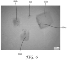
- the solid contents of the filter cake were examined under a microscope. Typical contents were observed in the filter cake, namely tiny broken parts (e.g., pieces of support geometries), semi-cured residues, and lint, as described above with respect to FIG. 6 .
Landscapes
- Chemical & Material Sciences (AREA)
- Engineering & Computer Science (AREA)
- Materials Engineering (AREA)
- Manufacturing & Machinery (AREA)
- Physics & Mathematics (AREA)
- Mechanical Engineering (AREA)
- Optics & Photonics (AREA)
- Chemical Kinetics & Catalysis (AREA)
Claims (15)
- Ein Verfahren, aufweisend:a) Erhalten eines Einsatzes (220), aufweisend ein Sieb (240), das eine Vielzahl von Öffnungen definiert;b) Einbringen eines Volumens eines Fluids in den Einsatz (220), wobei das Fluid eine fotopolymerisierbare Zusammensetzung und eine Verunreinigung aufweist; charakterisiert durchc) ein Aussetzen des Volumens des Fluids einer Zentrifugalkraft, um die Verunreinigung von mindestens einem Anteil der fotopolymerisierbaren Zusammensetzung zu trennen, durch Zurückhalten der Verunreinigung in dem Einsatz (220), und Leiten mindestens eines Anteils der fotopolymerisierbaren Zusammensetzung durch das Sieb (240) des Einsatzes (220), um eine getrennte fotopolymerisierbare Zusammensetzung bereitzustellen; und dadurch, dass die Öffnungen jeweils einen Durchmesser von 10 bis 200 Mikrometer aufweisen.
- Das Verfahren nach Anspruch 1, wobei mindestens ein Anteil des Einsatzes in einem Behälter angeordnet ist, der konfiguriert ist, um in eine Zentrifuge zu passen, und der Anteil der fotopolymerisierbaren Zusammensetzung, der durch das Sieb des Einsatzes geleitet wird, in einem Behälter gesammelt wird.
- Das Verfahren nach Anspruch 1 oder 2, wobei die Verunreinigung mindestens eines von einem Oligomer, einem Polymer, einem Staubpartikel, Flusen, einer Vielzahl von ausgehärteten Voxeln, die aus der fotopolymerisierbaren Zusammensetzung ausgebildet sind, oder einem Teil, das aus einem polymerisierten Produkt der fotopolymerisierbaren Zusammensetzung ausgebildet ist, aufweist.
- Das Verfahren nach einem der Ansprüche 1 bis 3, wobei die getrennte fotopolymerisierbare Zusammensetzung ferner einen Partikelfüllstoff aufweist, und das Verfahren ferner d) ein Unterziehen der getrennten fotopolymerisierbaren Zusammensetzung einer Homogenisierung aufweist.
- Das Verfahren nach Anspruch 4, wobei die Homogenisierung unter Vakuum durchgeführt wird.
- Das Verfahren gemäß einem der Ansprüche 1 bis 5, wobei Schritt c) bei Umgebungsdruck durchgeführt wird.
- Das Verfahren gemäß einem der Ansprüche 1 bis 6, wobei das Sieb ein erstes Sieb ist und der Einsatz ferner ein zweites Sieb, das neben dem ersten Sieb angeordnet ist, aufweist, wobei das zweite Sieb eine Vielzahl von Öffnungen definiert, die jeweils einen Durchmesser aufweisen, der kleiner als die Vielzahl von Öffnungen des ersten Siebs ist.
- Das Verfahren nach einem der Ansprüche 1 bis 7, ferner aufweisend e) ein Aussetzen der getrennten fotopolymerisierbaren Zusammensetzung einer zusätzlichen Zentrifugation, um mindestens einen Anteil eines gelösten Gases oder von Gasbläschen aus der fotopolymerisierbaren Zusammensetzung zu entfernen.
- Das Verfahren nach einem der Ansprüche 1 bis 8, ferner aufweisend, vor Schritt a), f) ein selektives Aushärten einer anfänglichen fotopolymerisierbaren Zusammensetzung unter Verwendung von aktinischer Strahlung, um ein dreidimensionales Objekt und das Fluid, aufweisend die fotopolymerisierbaren Zusammensetzung und die Verunreinigung, bereitzustellen.
- Das Verfahren nach Anspruch 9, ferner aufweisend g) ein Bewegen des dreidimensionalen Objekts und dadurch Erzeugen einer Massenträgheitskraft in einem Anteil des Fluids, der auf dem dreidimensionalen Objekt angeordnet ist, wobei die Massenträgheitskraft unter Verwendung einer Zentrifuge, eines Schüttlers oder eines Mischers, der sich entlang einer oder mehrerer Achsen dreht, erzeugt wird.
- Das Verfahren nach einem der Ansprüche 1 bis 10, ferner aufweisend i) ein Analysieren der getrennten fotopolymerisierbaren Zusammensetzung auf mindestens eines von Homogenität oder Fotoinitiatorgehalt.
- Das Verfahren nach einem der Ansprüche 1 bis 11, ferner aufweisend j) ein Einbringen von mindestens einem Anteil der getrennten fotopolymerisierbaren Zusammensetzung in eine Einrichtung für die additive Herstellung; und k) ein selektives Aushärten der getrennten fotopolymerisierbaren Zusammensetzung in der Einrichtung für die additive Herstellung unter Verwendung von aktinischer Strahlung, um ein dreidimensionales Objekt auszubilden.
- Das Verfahren nach Anspruch 12, ferner aufweisend, vor Schritt j) oder Schritt k), 1) ein Mischen von mindestens einem Anteil der getrennten fotopolymerisierbaren Zusammensetzung mit einem Volumen einer anfänglichen fotopolymerisierbaren Zusammensetzung.
- Ein System aufweisend:a) eine Einrichtung für die additive Herstellung (200);b) eine Zentrifuge (290); undc) einen Einsatz (220, 320), der konfiguriert ist, um in die Zentrifuge (290) eingesetzt zu werden, der Einsatz (220, 320) aufweisend ein Sieb, das eine Vielzahl von Öffnungen definiert, dadurch gekennzeichnet, dass diese Öffnungen jeweils einen Durchmesser von 10 bis 200 Mikrometer aufweisen.
- Das System nach Anspruch 14, wobei das Sieb ein erstes Sieb ist und der Einsatz ferner ein zweites Sieb aufweist, das neben dem ersten Sieb angeordnet ist, wobei das zweite Sieb eine Vielzahl von Öffnungen definiert, die jeweils einen Durchmesser aufweisen, der kleiner als die Vielzahl von Öffnungen des ersten Siebs ist.
Applications Claiming Priority (2)
| Application Number | Priority Date | Filing Date | Title |
|---|---|---|---|
| US202063106478P | 2020-10-28 | 2020-10-28 | |
| PCT/IB2021/058957 WO2022090831A1 (en) | 2020-10-28 | 2021-09-29 | Methods and systems for processing photopolymerizable compositions |
Publications (2)
| Publication Number | Publication Date |
|---|---|
| EP4237159A1 EP4237159A1 (de) | 2023-09-06 |
| EP4237159B1 true EP4237159B1 (de) | 2024-07-10 |
Family
ID=78294034
Family Applications (1)
| Application Number | Title | Priority Date | Filing Date |
|---|---|---|---|
| EP21794634.2A Active EP4237159B1 (de) | 2020-10-28 | 2021-09-29 | Verfahren und systeme zur verarbeitung von photopolymerisierbaren zusammensetzungen |
Country Status (5)
| Country | Link |
|---|---|
| US (1) | US12311289B2 (de) |
| EP (1) | EP4237159B1 (de) |
| JP (1) | JP2023547191A (de) |
| CN (1) | CN116528983A (de) |
| WO (1) | WO2022090831A1 (de) |
Families Citing this family (1)
| Publication number | Priority date | Publication date | Assignee | Title |
|---|---|---|---|---|
| KR102698804B1 (ko) * | 2023-10-30 | 2024-08-23 | 임이슬 | 3d 프린터용 조립식 수지 용기 |
Family Cites Families (29)
| Publication number | Priority date | Publication date | Assignee | Title |
|---|---|---|---|---|
| US4902310A (en) | 1989-05-16 | 1990-02-20 | Vara International, Inc. | Process for removing halogenated hydrocarbons from solvent streams |
| US5474719A (en) * | 1991-02-14 | 1995-12-12 | E. I. Du Pont De Nemours And Company | Method for forming solid objects utilizing viscosity reducible compositions |
| US6572693B1 (en) | 1999-10-28 | 2003-06-03 | 3M Innovative Properties Company | Aesthetic dental materials |
| US6730156B1 (en) | 1999-10-28 | 2004-05-04 | 3M Innovative Properties Company | Clustered particle dental fillers |
| AU3505400A (en) | 1999-10-28 | 2001-05-08 | 3M Innovative Properties Company | Dental materials with nano-sized silica particles |
| EP2008636A1 (de) | 2007-06-29 | 2008-12-31 | 3M Innovative Properties Company | Dentale Zusammensetzung mit polyfunktionalem (Meth)Acrylat mit Urethan-, Harnstoff- oder Amidgruppen, Verfahren zu deren Herstellung und Verwendung |
| CN101816983B (zh) * | 2009-02-27 | 2013-04-17 | 史志铭 | 一种用于高温熔体过滤的离心转子 |
| CN201423314Y (zh) * | 2009-02-27 | 2010-03-17 | 史志铭 | 一种用于高温熔体过滤的离心转子 |
| EP2654412B1 (de) | 2010-12-21 | 2019-10-16 | Stratasys Ltd. | Verfahren und system zur wiederverwendung von materialien in zusatzstoffherstellungssystemen |
| JP5831173B2 (ja) | 2011-11-29 | 2015-12-09 | 三菱瓦斯化学株式会社 | 安定化および再生方法 |
| CA2898106A1 (en) | 2013-02-12 | 2014-08-21 | Carbon3D, Inc. | Continuous liquid interphase printing |
| US9360757B2 (en) | 2013-08-14 | 2016-06-07 | Carbon3D, Inc. | Continuous liquid interphase printing |
| CN205871234U (zh) * | 2016-07-28 | 2017-01-11 | 上海数造机电科技股份有限公司 | 一种用于光固化快速成型的模型后处理装置 |
| BR112019004816A2 (pt) | 2016-09-12 | 2019-09-03 | Poly6 Tech Inc | método de reciclagem de alto desempenho, de um vaso, para resíduo de polímero usando síntese de polímero renovável |
| CN106640650B (zh) | 2016-12-30 | 2018-10-30 | 哈尔滨天顺化工科技开发有限公司 | 一种用于碳纤维原丝生产水环真空泵液体回收装置 |
| US20210107211A1 (en) * | 2017-03-23 | 2021-04-15 | Carbon, Inc. | Lip supports useful for making objects by additive manufacturing |
| CN106966566B (zh) | 2017-05-23 | 2019-09-24 | 杭州富阳钰宝机床厂 | 一种可进行两次高效干燥的污泥除杂干化装置 |
| EP3638189B1 (de) | 2017-06-14 | 2021-08-18 | 3M Innovative Properties Company | Härtbare zusammensetzung zur herstellung einer dentalverbundwerkstoffkrone und verfahren zur herstellung |
| US11433658B2 (en) * | 2017-07-26 | 2022-09-06 | 3M Innovative Properties Company | Method of making a physical object by additive manufacturing |
| EP3713741B1 (de) | 2017-11-21 | 2023-03-01 | 3M Innovative Properties Company | Verfahren zur herstellung eines physikalischen objekts |
| US12042994B2 (en) | 2018-03-02 | 2024-07-23 | Carbon, Inc. | Sustainable additive manufacturing resins and methods of recycling |
| US11332565B2 (en) | 2018-04-30 | 2022-05-17 | Board Of Supervisors Of Louisiana State University And Agricultural And Mechanical College | High performance and recyclable thermoset ink for 3D or 4D printing |
| US11390705B2 (en) | 2018-05-11 | 2022-07-19 | Carbon, Inc. | Reactive particulate materials useful for additive manufacturing |
| CN208601935U (zh) | 2018-08-07 | 2019-03-15 | 于龙宇 | 一种3d打印机的废料回收系统 |
| GB2580149A (en) * | 2018-12-21 | 2020-07-15 | Gkn Aerospace Services Ltd | Powder recovery system |
| WO2020139858A1 (en) * | 2018-12-26 | 2020-07-02 | Holo, Inc. | Sensors for three-dimensional printing systems and methods |
| CN113286560A (zh) | 2019-01-29 | 2021-08-20 | 3M创新有限公司 | 正畸制品及其制备和后处理方法 |
| CN110271193A (zh) | 2019-06-11 | 2019-09-24 | 安徽徽博先临三维云打印技术有限公司 | 树脂支撑表面液态树脂的回收再利用装置 |
| CN111331839B (zh) | 2020-03-11 | 2025-05-27 | 上海联泰科技股份有限公司 | 3d打印设备的过滤系统、方法及适用的3d打印设备 |
-
2021
- 2021-09-29 EP EP21794634.2A patent/EP4237159B1/de active Active
- 2021-09-29 US US18/249,937 patent/US12311289B2/en active Active
- 2021-09-29 WO PCT/IB2021/058957 patent/WO2022090831A1/en not_active Ceased
- 2021-09-29 JP JP2023525954A patent/JP2023547191A/ja not_active Withdrawn
- 2021-09-29 CN CN202180073255.9A patent/CN116528983A/zh active Pending
Also Published As
| Publication number | Publication date |
|---|---|
| CN116528983A (zh) | 2023-08-01 |
| WO2022090831A1 (en) | 2022-05-05 |
| EP4237159A1 (de) | 2023-09-06 |
| JP2023547191A (ja) | 2023-11-09 |
| US12311289B2 (en) | 2025-05-27 |
| US20230390673A1 (en) | 2023-12-07 |
Similar Documents
| Publication | Publication Date | Title |
|---|---|---|
| EP3658303B1 (de) | Verfahren zur herstellung eines physischen objekts durch generative fertigung | |
| EP3625056B1 (de) | Dreidimensionale drucksysteme und -verfahren für viskose filme | |
| US11161301B2 (en) | Viscous film three-dimensional printing systems and methods | |
| US11759299B2 (en) | Dental stereolithography-type three-dimensional printing material for preparing dental three-dimensional modeled object | |
| EP3713741B1 (de) | Verfahren zur herstellung eines physikalischen objekts | |
| EP4237159B1 (de) | Verfahren und systeme zur verarbeitung von photopolymerisierbaren zusammensetzungen | |
| US20210214556A1 (en) | Radiation-curable composition containing mercapto-functional polyorganosiloxanes for additive-manufacturing technology | |
| Sheydaeian et al. | Material process development for the fabrication of heterogeneous titanium structures with selective pore morphology by a hybrid additive manufacturing process | |
| WO2020210433A1 (en) | Systems and methods for printing a three-dimensional object | |
| WO2021220095A1 (en) | Methods of making additive manufactured articles using multilayer articles, objects prepared by the methods, and multilayer articles | |
| CN115943071A (zh) | 用于叠加制造技术的含有巯基官能化聚有机硅氧烷的可辐射固化组合物 | |
| WO2022225854A1 (en) | Systems and methods for stereolithography three-dimensional printing | |
| EP4072782A1 (de) | Schleifmittelgegenstände mit polymerbindung mit kontinuierlicher polymermatrix und verfahren zu deren herstellung | |
| Piazza | Evaluation of ceramic-oligomer interactions in DLP resins for biomedical applications | |
| WO2024250078A1 (en) | Methods and systems for fabricating three-dimensional objects by additive manufacturing | |
| US20240277582A1 (en) | Free-radically polymerizable compositions for 3d printing of dental crowns, bridges, prosthetic teeth or full prostheses |
Legal Events
| Date | Code | Title | Description |
|---|---|---|---|
| STAA | Information on the status of an ep patent application or granted ep patent |
Free format text: STATUS: UNKNOWN |
|
| STAA | Information on the status of an ep patent application or granted ep patent |
Free format text: STATUS: THE INTERNATIONAL PUBLICATION HAS BEEN MADE |
|
| PUAI | Public reference made under article 153(3) epc to a published international application that has entered the european phase |
Free format text: ORIGINAL CODE: 0009012 |
|
| STAA | Information on the status of an ep patent application or granted ep patent |
Free format text: STATUS: REQUEST FOR EXAMINATION WAS MADE |
|
| 17P | Request for examination filed |
Effective date: 20230425 |
|
| AK | Designated contracting states |
Kind code of ref document: A1 Designated state(s): AL AT BE BG CH CY CZ DE DK EE ES FI FR GB GR HR HU IE IS IT LI LT LU LV MC MK MT NL NO PL PT RO RS SE SI SK SM TR |
|
| RIC1 | Information provided on ipc code assigned before grant |
Ipc: B29C 64/35 20170101ALI20231219BHEP Ipc: B29C 64/124 20170101ALI20231219BHEP Ipc: B04B 5/04 20060101ALI20231219BHEP Ipc: B04B 7/18 20060101ALI20231219BHEP Ipc: B33Y 40/20 20200101ALI20231219BHEP Ipc: B04B 5/02 20060101AFI20231219BHEP |
|
| DAV | Request for validation of the european patent (deleted) | ||
| DAX | Request for extension of the european patent (deleted) | ||
| GRAP | Despatch of communication of intention to grant a patent |
Free format text: ORIGINAL CODE: EPIDOSNIGR1 |
|
| STAA | Information on the status of an ep patent application or granted ep patent |
Free format text: STATUS: GRANT OF PATENT IS INTENDED |
|
| INTG | Intention to grant announced |
Effective date: 20240209 |
|
| GRAJ | Information related to disapproval of communication of intention to grant by the applicant or resumption of examination proceedings by the epo deleted |
Free format text: ORIGINAL CODE: EPIDOSDIGR1 |
|
| STAA | Information on the status of an ep patent application or granted ep patent |
Free format text: STATUS: REQUEST FOR EXAMINATION WAS MADE |
|
| RAP1 | Party data changed (applicant data changed or rights of an application transferred) |
Owner name: SOLVENTUM INTELLECTUAL PROPERTIES COMPANY |
|
| INTC | Intention to grant announced (deleted) | ||
| GRAP | Despatch of communication of intention to grant a patent |
Free format text: ORIGINAL CODE: EPIDOSNIGR1 |
|
| STAA | Information on the status of an ep patent application or granted ep patent |
Free format text: STATUS: GRANT OF PATENT IS INTENDED |
|
| GRAS | Grant fee paid |
Free format text: ORIGINAL CODE: EPIDOSNIGR3 |
|
| INTG | Intention to grant announced |
Effective date: 20240508 |
|
| GRAA | (expected) grant |
Free format text: ORIGINAL CODE: 0009210 |
|
| STAA | Information on the status of an ep patent application or granted ep patent |
Free format text: STATUS: THE PATENT HAS BEEN GRANTED |
|
| AK | Designated contracting states |
Kind code of ref document: B1 Designated state(s): AL AT BE BG CH CY CZ DE DK EE ES FI FR GB GR HR HU IE IS IT LI LT LU LV MC MK MT NL NO PL PT RO RS SE SI SK SM TR |
|
| REG | Reference to a national code |
Ref country code: CH Ref legal event code: EP |
|
| REG | Reference to a national code |
Ref country code: DE Ref legal event code: R096 Ref document number: 602021015596 Country of ref document: DE |
|
| REG | Reference to a national code |
Ref country code: LT Ref legal event code: MG9D |
|
| REG | Reference to a national code |
Ref country code: NL Ref legal event code: MP Effective date: 20240710 |
|
| PG25 | Lapsed in a contracting state [announced via postgrant information from national office to epo] |
Ref country code: PT Free format text: LAPSE BECAUSE OF FAILURE TO SUBMIT A TRANSLATION OF THE DESCRIPTION OR TO PAY THE FEE WITHIN THE PRESCRIBED TIME-LIMIT Effective date: 20241111 |
|
| REG | Reference to a national code |
Ref country code: AT Ref legal event code: MK05 Ref document number: 1701599 Country of ref document: AT Kind code of ref document: T Effective date: 20240710 |
|
| PG25 | Lapsed in a contracting state [announced via postgrant information from national office to epo] |
Ref country code: NL Free format text: LAPSE BECAUSE OF FAILURE TO SUBMIT A TRANSLATION OF THE DESCRIPTION OR TO PAY THE FEE WITHIN THE PRESCRIBED TIME-LIMIT Effective date: 20240710 |
|
| PG25 | Lapsed in a contracting state [announced via postgrant information from national office to epo] |
Ref country code: PT Free format text: LAPSE BECAUSE OF FAILURE TO SUBMIT A TRANSLATION OF THE DESCRIPTION OR TO PAY THE FEE WITHIN THE PRESCRIBED TIME-LIMIT Effective date: 20241111 Ref country code: NL Free format text: LAPSE BECAUSE OF FAILURE TO SUBMIT A TRANSLATION OF THE DESCRIPTION OR TO PAY THE FEE WITHIN THE PRESCRIBED TIME-LIMIT Effective date: 20240710 |
|
| PG25 | Lapsed in a contracting state [announced via postgrant information from national office to epo] |
Ref country code: NO Free format text: LAPSE BECAUSE OF FAILURE TO SUBMIT A TRANSLATION OF THE DESCRIPTION OR TO PAY THE FEE WITHIN THE PRESCRIBED TIME-LIMIT Effective date: 20241010 |
|
| PG25 | Lapsed in a contracting state [announced via postgrant information from national office to epo] |
Ref country code: GR Free format text: LAPSE BECAUSE OF FAILURE TO SUBMIT A TRANSLATION OF THE DESCRIPTION OR TO PAY THE FEE WITHIN THE PRESCRIBED TIME-LIMIT Effective date: 20241011 Ref country code: FI Free format text: LAPSE BECAUSE OF FAILURE TO SUBMIT A TRANSLATION OF THE DESCRIPTION OR TO PAY THE FEE WITHIN THE PRESCRIBED TIME-LIMIT Effective date: 20240710 Ref country code: PL Free format text: LAPSE BECAUSE OF FAILURE TO SUBMIT A TRANSLATION OF THE DESCRIPTION OR TO PAY THE FEE WITHIN THE PRESCRIBED TIME-LIMIT Effective date: 20240710 |
|
| PG25 | Lapsed in a contracting state [announced via postgrant information from national office to epo] |
Ref country code: BG Free format text: LAPSE BECAUSE OF FAILURE TO SUBMIT A TRANSLATION OF THE DESCRIPTION OR TO PAY THE FEE WITHIN THE PRESCRIBED TIME-LIMIT Effective date: 20240710 |
|
| PG25 | Lapsed in a contracting state [announced via postgrant information from national office to epo] |
Ref country code: LV Free format text: LAPSE BECAUSE OF FAILURE TO SUBMIT A TRANSLATION OF THE DESCRIPTION OR TO PAY THE FEE WITHIN THE PRESCRIBED TIME-LIMIT Effective date: 20240710 |
|
| PG25 | Lapsed in a contracting state [announced via postgrant information from national office to epo] |
Ref country code: IS Free format text: LAPSE BECAUSE OF FAILURE TO SUBMIT A TRANSLATION OF THE DESCRIPTION OR TO PAY THE FEE WITHIN THE PRESCRIBED TIME-LIMIT Effective date: 20241110 Ref country code: AT Free format text: LAPSE BECAUSE OF FAILURE TO SUBMIT A TRANSLATION OF THE DESCRIPTION OR TO PAY THE FEE WITHIN THE PRESCRIBED TIME-LIMIT Effective date: 20240710 |
|
| PG25 | Lapsed in a contracting state [announced via postgrant information from national office to epo] |
Ref country code: HR Free format text: LAPSE BECAUSE OF FAILURE TO SUBMIT A TRANSLATION OF THE DESCRIPTION OR TO PAY THE FEE WITHIN THE PRESCRIBED TIME-LIMIT Effective date: 20240710 |
|
| PG25 | Lapsed in a contracting state [announced via postgrant information from national office to epo] |
Ref country code: ES Free format text: LAPSE BECAUSE OF FAILURE TO SUBMIT A TRANSLATION OF THE DESCRIPTION OR TO PAY THE FEE WITHIN THE PRESCRIBED TIME-LIMIT Effective date: 20240710 Ref country code: RS Free format text: LAPSE BECAUSE OF FAILURE TO SUBMIT A TRANSLATION OF THE DESCRIPTION OR TO PAY THE FEE WITHIN THE PRESCRIBED TIME-LIMIT Effective date: 20241010 |
|
| PG25 | Lapsed in a contracting state [announced via postgrant information from national office to epo] |
Ref country code: RS Free format text: LAPSE BECAUSE OF FAILURE TO SUBMIT A TRANSLATION OF THE DESCRIPTION OR TO PAY THE FEE WITHIN THE PRESCRIBED TIME-LIMIT Effective date: 20241010 Ref country code: PL Free format text: LAPSE BECAUSE OF FAILURE TO SUBMIT A TRANSLATION OF THE DESCRIPTION OR TO PAY THE FEE WITHIN THE PRESCRIBED TIME-LIMIT Effective date: 20240710 Ref country code: NO Free format text: LAPSE BECAUSE OF FAILURE TO SUBMIT A TRANSLATION OF THE DESCRIPTION OR TO PAY THE FEE WITHIN THE PRESCRIBED TIME-LIMIT Effective date: 20241010 Ref country code: LV Free format text: LAPSE BECAUSE OF FAILURE TO SUBMIT A TRANSLATION OF THE DESCRIPTION OR TO PAY THE FEE WITHIN THE PRESCRIBED TIME-LIMIT Effective date: 20240710 Ref country code: IS Free format text: LAPSE BECAUSE OF FAILURE TO SUBMIT A TRANSLATION OF THE DESCRIPTION OR TO PAY THE FEE WITHIN THE PRESCRIBED TIME-LIMIT Effective date: 20241110 Ref country code: HR Free format text: LAPSE BECAUSE OF FAILURE TO SUBMIT A TRANSLATION OF THE DESCRIPTION OR TO PAY THE FEE WITHIN THE PRESCRIBED TIME-LIMIT Effective date: 20240710 Ref country code: GR Free format text: LAPSE BECAUSE OF FAILURE TO SUBMIT A TRANSLATION OF THE DESCRIPTION OR TO PAY THE FEE WITHIN THE PRESCRIBED TIME-LIMIT Effective date: 20241011 Ref country code: FI Free format text: LAPSE BECAUSE OF FAILURE TO SUBMIT A TRANSLATION OF THE DESCRIPTION OR TO PAY THE FEE WITHIN THE PRESCRIBED TIME-LIMIT Effective date: 20240710 Ref country code: ES Free format text: LAPSE BECAUSE OF FAILURE TO SUBMIT A TRANSLATION OF THE DESCRIPTION OR TO PAY THE FEE WITHIN THE PRESCRIBED TIME-LIMIT Effective date: 20240710 Ref country code: BG Free format text: LAPSE BECAUSE OF FAILURE TO SUBMIT A TRANSLATION OF THE DESCRIPTION OR TO PAY THE FEE WITHIN THE PRESCRIBED TIME-LIMIT Effective date: 20240710 Ref country code: AT Free format text: LAPSE BECAUSE OF FAILURE TO SUBMIT A TRANSLATION OF THE DESCRIPTION OR TO PAY THE FEE WITHIN THE PRESCRIBED TIME-LIMIT Effective date: 20240710 |
|
| REG | Reference to a national code |
Ref country code: DE Ref legal event code: R097 Ref document number: 602021015596 Country of ref document: DE |
|
| PG25 | Lapsed in a contracting state [announced via postgrant information from national office to epo] |
Ref country code: RO Free format text: LAPSE BECAUSE OF FAILURE TO SUBMIT A TRANSLATION OF THE DESCRIPTION OR TO PAY THE FEE WITHIN THE PRESCRIBED TIME-LIMIT Effective date: 20240710 Ref country code: SM Free format text: LAPSE BECAUSE OF FAILURE TO SUBMIT A TRANSLATION OF THE DESCRIPTION OR TO PAY THE FEE WITHIN THE PRESCRIBED TIME-LIMIT Effective date: 20240710 Ref country code: DK Free format text: LAPSE BECAUSE OF FAILURE TO SUBMIT A TRANSLATION OF THE DESCRIPTION OR TO PAY THE FEE WITHIN THE PRESCRIBED TIME-LIMIT Effective date: 20240710 |
|
| PG25 | Lapsed in a contracting state [announced via postgrant information from national office to epo] |
Ref country code: EE Free format text: LAPSE BECAUSE OF FAILURE TO SUBMIT A TRANSLATION OF THE DESCRIPTION OR TO PAY THE FEE WITHIN THE PRESCRIBED TIME-LIMIT Effective date: 20240710 Ref country code: MC Free format text: LAPSE BECAUSE OF FAILURE TO SUBMIT A TRANSLATION OF THE DESCRIPTION OR TO PAY THE FEE WITHIN THE PRESCRIBED TIME-LIMIT Effective date: 20240710 |
|
| PG25 | Lapsed in a contracting state [announced via postgrant information from national office to epo] |
Ref country code: CZ Free format text: LAPSE BECAUSE OF FAILURE TO SUBMIT A TRANSLATION OF THE DESCRIPTION OR TO PAY THE FEE WITHIN THE PRESCRIBED TIME-LIMIT Effective date: 20240710 |
|
| PG25 | Lapsed in a contracting state [announced via postgrant information from national office to epo] |
Ref country code: SK Free format text: LAPSE BECAUSE OF FAILURE TO SUBMIT A TRANSLATION OF THE DESCRIPTION OR TO PAY THE FEE WITHIN THE PRESCRIBED TIME-LIMIT Effective date: 20240710 Ref country code: IT Free format text: LAPSE BECAUSE OF FAILURE TO SUBMIT A TRANSLATION OF THE DESCRIPTION OR TO PAY THE FEE WITHIN THE PRESCRIBED TIME-LIMIT Effective date: 20240710 |
|
| REG | Reference to a national code |
Ref country code: CH Ref legal event code: PL |
|
| PLBE | No opposition filed within time limit |
Free format text: ORIGINAL CODE: 0009261 |
|
| STAA | Information on the status of an ep patent application or granted ep patent |
Free format text: STATUS: NO OPPOSITION FILED WITHIN TIME LIMIT |
|
| PG25 | Lapsed in a contracting state [announced via postgrant information from national office to epo] |
Ref country code: LU Free format text: LAPSE BECAUSE OF NON-PAYMENT OF DUE FEES Effective date: 20240929 |
|
| 26N | No opposition filed |
Effective date: 20250411 |
|
| REG | Reference to a national code |
Ref country code: BE Ref legal event code: MM Effective date: 20240930 |
|
| PG25 | Lapsed in a contracting state [announced via postgrant information from national office to epo] |
Ref country code: BE Free format text: LAPSE BECAUSE OF NON-PAYMENT OF DUE FEES Effective date: 20240930 |
|
| PG25 | Lapsed in a contracting state [announced via postgrant information from national office to epo] |
Ref country code: FR Free format text: LAPSE BECAUSE OF NON-PAYMENT OF DUE FEES Effective date: 20240930 |
|
| PG25 | Lapsed in a contracting state [announced via postgrant information from national office to epo] |
Ref country code: CH Free format text: LAPSE BECAUSE OF NON-PAYMENT OF DUE FEES Effective date: 20240930 |
|
| PG25 | Lapsed in a contracting state [announced via postgrant information from national office to epo] |
Ref country code: IE Free format text: LAPSE BECAUSE OF NON-PAYMENT OF DUE FEES Effective date: 20240929 |
|
| PG25 | Lapsed in a contracting state [announced via postgrant information from national office to epo] |
Ref country code: SE Free format text: LAPSE BECAUSE OF FAILURE TO SUBMIT A TRANSLATION OF THE DESCRIPTION OR TO PAY THE FEE WITHIN THE PRESCRIBED TIME-LIMIT Effective date: 20240710 |
|
| PGFP | Annual fee paid to national office [announced via postgrant information from national office to epo] |
Ref country code: DE Payment date: 20250820 Year of fee payment: 5 |