EP4237140B1 - Gemischtes katalytisches system zur umwandlung von co2 und/oder co in einem hybriden kaltplasmakatalyseverfahren - Google Patents
Gemischtes katalytisches system zur umwandlung von co2 und/oder co in einem hybriden kaltplasmakatalyseverfahren Download PDFInfo
- Publication number
- EP4237140B1 EP4237140B1 EP21810673.0A EP21810673A EP4237140B1 EP 4237140 B1 EP4237140 B1 EP 4237140B1 EP 21810673 A EP21810673 A EP 21810673A EP 4237140 B1 EP4237140 B1 EP 4237140B1
- Authority
- EP
- European Patent Office
- Prior art keywords
- support
- promoter
- nickel
- catalytic system
- catalytic
- Prior art date
- Legal status (The legal status is an assumption and is not a legal conclusion. Google has not performed a legal analysis and makes no representation as to the accuracy of the status listed.)
- Active
Links
Images


Classifications
-
- B—PERFORMING OPERATIONS; TRANSPORTING
- B01—PHYSICAL OR CHEMICAL PROCESSES OR APPARATUS IN GENERAL
- B01J—CHEMICAL OR PHYSICAL PROCESSES, e.g. CATALYSIS OR COLLOID CHEMISTRY; THEIR RELEVANT APPARATUS
- B01J23/00—Catalysts comprising metals or metal oxides or hydroxides, not provided for in group B01J21/00
- B01J23/70—Catalysts comprising metals or metal oxides or hydroxides, not provided for in group B01J21/00 of the iron group metals or copper
- B01J23/74—Iron group metals
- B01J23/755—Nickel
-
- B—PERFORMING OPERATIONS; TRANSPORTING
- B01—PHYSICAL OR CHEMICAL PROCESSES OR APPARATUS IN GENERAL
- B01J—CHEMICAL OR PHYSICAL PROCESSES, e.g. CATALYSIS OR COLLOID CHEMISTRY; THEIR RELEVANT APPARATUS
- B01J19/00—Chemical, physical or physico-chemical processes in general; Their relevant apparatus
- B01J19/08—Processes employing the direct application of electric or wave energy, or particle radiation; Apparatus therefor
- B01J19/087—Processes employing the direct application of electric or wave energy, or particle radiation; Apparatus therefor employing electric or magnetic energy
- B01J19/088—Processes employing the direct application of electric or wave energy, or particle radiation; Apparatus therefor employing electric or magnetic energy giving rise to electric discharges
-
- B—PERFORMING OPERATIONS; TRANSPORTING
- B01—PHYSICAL OR CHEMICAL PROCESSES OR APPARATUS IN GENERAL
- B01J—CHEMICAL OR PHYSICAL PROCESSES, e.g. CATALYSIS OR COLLOID CHEMISTRY; THEIR RELEVANT APPARATUS
- B01J21/00—Catalysts comprising the elements, oxides, or hydroxides of magnesium, boron, aluminium, carbon, silicon, titanium, zirconium, or hafnium
- B01J21/06—Silicon, titanium, zirconium or hafnium; Oxides or hydroxides thereof
- B01J21/066—Zirconium or hafnium; Oxides or hydroxides thereof
-
- B—PERFORMING OPERATIONS; TRANSPORTING
- B01—PHYSICAL OR CHEMICAL PROCESSES OR APPARATUS IN GENERAL
- B01J—CHEMICAL OR PHYSICAL PROCESSES, e.g. CATALYSIS OR COLLOID CHEMISTRY; THEIR RELEVANT APPARATUS
- B01J23/00—Catalysts comprising metals or metal oxides or hydroxides, not provided for in group B01J21/00
- B01J23/10—Catalysts comprising metals or metal oxides or hydroxides, not provided for in group B01J21/00 of rare earths
-
- B—PERFORMING OPERATIONS; TRANSPORTING
- B01—PHYSICAL OR CHEMICAL PROCESSES OR APPARATUS IN GENERAL
- B01J—CHEMICAL OR PHYSICAL PROCESSES, e.g. CATALYSIS OR COLLOID CHEMISTRY; THEIR RELEVANT APPARATUS
- B01J23/00—Catalysts comprising metals or metal oxides or hydroxides, not provided for in group B01J21/00
- B01J23/70—Catalysts comprising metals or metal oxides or hydroxides, not provided for in group B01J21/00 of the iron group metals or copper
- B01J23/76—Catalysts comprising metals or metal oxides or hydroxides, not provided for in group B01J21/00 of the iron group metals or copper combined with metals, oxides or hydroxides provided for in groups B01J23/02 - B01J23/36
- B01J23/83—Catalysts comprising metals or metal oxides or hydroxides, not provided for in group B01J21/00 of the iron group metals or copper combined with metals, oxides or hydroxides provided for in groups B01J23/02 - B01J23/36 with rare earths or actinides
-
- B—PERFORMING OPERATIONS; TRANSPORTING
- B01—PHYSICAL OR CHEMICAL PROCESSES OR APPARATUS IN GENERAL
- B01J—CHEMICAL OR PHYSICAL PROCESSES, e.g. CATALYSIS OR COLLOID CHEMISTRY; THEIR RELEVANT APPARATUS
- B01J37/00—Processes, in general, for preparing catalysts; Processes, in general, for activation of catalysts
- B01J37/08—Heat treatment
-
- C—CHEMISTRY; METALLURGY
- C07—ORGANIC CHEMISTRY
- C07C—ACYCLIC OR CARBOCYCLIC COMPOUNDS
- C07C1/00—Preparation of hydrocarbons from one or more compounds, none of them being a hydrocarbon
- C07C1/02—Preparation of hydrocarbons from one or more compounds, none of them being a hydrocarbon from oxides of a carbon
- C07C1/12—Preparation of hydrocarbons from one or more compounds, none of them being a hydrocarbon from oxides of a carbon from carbon dioxide with hydrogen
-
- C—CHEMISTRY; METALLURGY
- C10—PETROLEUM, GAS OR COKE INDUSTRIES; TECHNICAL GASES CONTAINING CARBON MONOXIDE; FUELS; LUBRICANTS; PEAT
- C10L—FUELS NOT OTHERWISE PROVIDED FOR; NATURAL GAS; SYNTHETIC NATURAL GAS OBTAINED BY PROCESSES NOT COVERED BY SUBCLASSES C10G OR C10K; LIQUIFIED PETROLEUM GAS; USE OF ADDITIVES TO FUELS OR FIRES; FIRE-LIGHTERS
- C10L3/00—Gaseous fuels; Natural gas; Synthetic natural gas obtained by processes not covered by subclass C10G, C10K; Liquefied petroleum gas
- C10L3/06—Natural gas; Synthetic natural gas obtained by processes not covered by C10G, C10K3/02 or C10K3/04
- C10L3/08—Production of synthetic natural gas
-
- B—PERFORMING OPERATIONS; TRANSPORTING
- B01—PHYSICAL OR CHEMICAL PROCESSES OR APPARATUS IN GENERAL
- B01J—CHEMICAL OR PHYSICAL PROCESSES, e.g. CATALYSIS OR COLLOID CHEMISTRY; THEIR RELEVANT APPARATUS
- B01J2219/00—Chemical, physical or physico-chemical processes in general; Their relevant apparatus
- B01J2219/08—Processes employing the direct application of electric or wave energy, or particle radiation; Apparatus therefor
- B01J2219/0873—Materials to be treated
- B01J2219/0892—Materials to be treated involving catalytically active material
-
- B—PERFORMING OPERATIONS; TRANSPORTING
- B01—PHYSICAL OR CHEMICAL PROCESSES OR APPARATUS IN GENERAL
- B01J—CHEMICAL OR PHYSICAL PROCESSES, e.g. CATALYSIS OR COLLOID CHEMISTRY; THEIR RELEVANT APPARATUS
- B01J2219/00—Chemical, physical or physico-chemical processes in general; Their relevant apparatus
- B01J2219/08—Processes employing the direct application of electric or wave energy, or particle radiation; Apparatus therefor
- B01J2219/0894—Processes carried out in the presence of a plasma
- B01J2219/0896—Cold plasma
-
- B—PERFORMING OPERATIONS; TRANSPORTING
- B01—PHYSICAL OR CHEMICAL PROCESSES OR APPARATUS IN GENERAL
- B01J—CHEMICAL OR PHYSICAL PROCESSES, e.g. CATALYSIS OR COLLOID CHEMISTRY; THEIR RELEVANT APPARATUS
- B01J37/00—Processes, in general, for preparing catalysts; Processes, in general, for activation of catalysts
- B01J37/16—Reducing
-
- C—CHEMISTRY; METALLURGY
- C07—ORGANIC CHEMISTRY
- C07C—ACYCLIC OR CARBOCYCLIC COMPOUNDS
- C07C2521/00—Catalysts comprising the elements, oxides or hydroxides of magnesium, boron, aluminium, carbon, silicon, titanium, zirconium or hafnium
- C07C2521/06—Silicon, titanium, zirconium or hafnium; Oxides or hydroxides thereof
-
- C—CHEMISTRY; METALLURGY
- C07—ORGANIC CHEMISTRY
- C07C—ACYCLIC OR CARBOCYCLIC COMPOUNDS
- C07C2523/00—Catalysts comprising metals or metal oxides or hydroxides, not provided for in group C07C2521/00
- C07C2523/10—Catalysts comprising metals or metal oxides or hydroxides, not provided for in group C07C2521/00 of rare earths
-
- C—CHEMISTRY; METALLURGY
- C07—ORGANIC CHEMISTRY
- C07C—ACYCLIC OR CARBOCYCLIC COMPOUNDS
- C07C2523/00—Catalysts comprising metals or metal oxides or hydroxides, not provided for in group C07C2521/00
- C07C2523/70—Catalysts comprising metals or metal oxides or hydroxides, not provided for in group C07C2521/00 of the iron group metals or copper
- C07C2523/74—Iron group metals
- C07C2523/755—Nickel
-
- C—CHEMISTRY; METALLURGY
- C07—ORGANIC CHEMISTRY
- C07C—ACYCLIC OR CARBOCYCLIC COMPOUNDS
- C07C2523/00—Catalysts comprising metals or metal oxides or hydroxides, not provided for in group C07C2521/00
- C07C2523/70—Catalysts comprising metals or metal oxides or hydroxides, not provided for in group C07C2521/00 of the iron group metals or copper
- C07C2523/76—Catalysts comprising metals or metal oxides or hydroxides, not provided for in group C07C2521/00 of the iron group metals or copper combined with metals, oxides or hydroxides provided for in groups C07C2523/02 - C07C2523/36
- C07C2523/83—Catalysts comprising metals or metal oxides or hydroxides, not provided for in group C07C2521/00 of the iron group metals or copper combined with metals, oxides or hydroxides provided for in groups C07C2523/02 - C07C2523/36 with rare earths or actinides
-
- C—CHEMISTRY; METALLURGY
- C10—PETROLEUM, GAS OR COKE INDUSTRIES; TECHNICAL GASES CONTAINING CARBON MONOXIDE; FUELS; LUBRICANTS; PEAT
- C10L—FUELS NOT OTHERWISE PROVIDED FOR; NATURAL GAS; SYNTHETIC NATURAL GAS OBTAINED BY PROCESSES NOT COVERED BY SUBCLASSES C10G OR C10K; LIQUIFIED PETROLEUM GAS; USE OF ADDITIVES TO FUELS OR FIRES; FIRE-LIGHTERS
- C10L2290/00—Fuel preparation or upgrading, processes or apparatus therefore, comprising specific process steps or apparatus units
- C10L2290/38—Applying an electric field or inclusion of electrodes in the apparatus
Definitions
- the present invention relates to a novel catalytic system capable of being activated by a cold plasma, in particular generated by "dielectric barrier discharge", known as DBD plasma, and the process for preparing said catalytic system.
- the invention also relates to a process for converting CO 2 and/or CO using said catalytic system, for example to produce hydrocarbons, in particular methane, alcohols, carbon monoxide or even formic acid.
- the Sabatier reaction is exothermic and thermodynamically favorable at low temperatures. However, it is seriously hampered by its slow reaction kinetics due to the high stability of CO 2 . Thus, the use of catalysts is essential to achieve a satisfactory conversion rate.
- Ocampo et al. (1) described the use of solid solutions of mixed cerium and zirconium oxide for the preparation of nickel catalysts for CO 2 methanation.
- the mixed oxides CeO 2 -ZrO 2 exhibit good physicochemical characteristics, such as good oxygen storage capacity and mobility, surface basicity increased promoting CO2 adsorption, as well as adequate thermal stability.
- Non-thermal plasmas including plasmas generated by dielectric barrier discharge (DBD)
- DBD dielectric barrier discharge
- Such a hybrid plasma-catalysis process has several advantages over conventional catalysis, as it operates at atmospheric pressure. This hybrid process can be carried out at low temperatures (e.g. 180°C-240°C) and achieves better methane selectivity (> 95%), without any side reactions. However, it remains very energy-intensive. The energy cost is defined as the amount of energy consumed by the process per molecule converted, often expressed in kJ or eV per molecule.
- the inventors have previously demonstrated the effective combination of a catalyst based on mixed cerium and zirconium oxide, impregnated with nickel with a cold plasma such as a DBD plasma to carry out the Sabatier reaction at low temperature (e.g. below 250°C) (10).
- a cold plasma such as a DBD plasma
- the energy consumption remains significant to obtain a satisfactory CO2 conversion rate.
- An aim of the invention is therefore to propose a new catalyst, also called a catalytic system, for converting CO 2 and/or CO into fuel, including hydrocarbons, alcohols, formic acid, carbon monoxide (if the reaction is carried out from CO 2 ) and their mixtures, with reduced energy consumption and an improved CO 2 and/or CO conversion rate compared to those described in the prior art.
- a new catalyst also called a catalytic system
- a second object of the present invention relates to a method for preparing a system catalytic as defined above by contacting the support or a precursor thereof with a nickel precursor and a precursor of the promoter.
- a third subject of the present invention relates to a method for converting a gas comprising CO 2 and/or CO in the presence of a catalytic system as defined above and a cold plasma.
- catalytic system and “catalyst” are interchangeable.
- the support according to the invention is notably chosen for its capacity to adsorb CO 2 and/or CO on its surface and its thermal stability.
- cerium and zirconium are meant in the sense of the present invention cerium and zirconium in all their oxidation states.
- the term "cerium” used to define the support denotes cerium oxide CeO 2 and the term “zirconium” denotes zirconium oxide ZrO 2 .
- the support may thus comprise, in particular be made up of, cerium, zirconium or a mixture of cerium and zirconium.
- the support comprises, in particular is made up of cerium, possibly in combination with zirconium.
- the support of the catalytic system comprises, in particular is made up of, a mixture of cerium and zirconium.
- the support may thus comprise, in particular be made up of, a cerium oxide, a zirconium oxide or a mixed oxide of cerium and zirconium.
- the support comprises, in particular is made up of, cerium oxide, possibly in combination with zirconium oxide.
- the support of the catalytic system comprises, in particular is made up of, a mixed oxide of cerium and zirconium (abbreviated CeO 2 -ZrO 2 or mixed oxide CeZr or CZ).
- the cerium/zirconium (Ce/Zr) molar ratio is advantageously in a range from 90/10 to 40/60, preferably from 80/20 to 50/50, in particular 70/30 to 50/50.
- the cerium/zirconium ratio is approximately 60/40.
- the Ce/Zr ratio will in particular modulate the catalytic performance of the system. Indeed, the adsorption of the reactants on the surface of the support is generally favored by the presence of inherent defects present on said surface, mainly due to a lack of oxygen.
- the addition of Zr4+ ions into the cerium oxide lattice during the formation of CeZr mixed oxide allows a higher number of defects and promotes oxygen mobility at the support surface, thus leading to increased catalytic performance.
- Nickel corresponds to the active phase of the catalytic system.
- nickel is meant in the sense of the present invention nickel in all its oxidation states. It may thus be nickel in its oxidation state 0, that is to say in metallic form, in its oxidation state II (e.g. in the form of nickel (II) oxide (NiO)) or in its oxidation state III (e.g. in the form of nickel (III) oxide (Ni 2 O 3 )).
- the mass content of nickel in the catalytic system advantageously ranges from 3% to 30% by weight relative to the weight of the support, preferably from 5% to 20%, even more preferably from 7% to 17%. In such a way particularly advantageous, the catalytic system comprises approximately 15% by weight of nickel relative to the weight of the support.
- the catalytic system according to the invention makes it possible to improve the energy performance during the conversion, in particular the hydrogenation, of the gas comprising CO 2 and/or CO in the presence of a non-thermal plasma with a reduction in the power consumed, and preferably while improving the catalytic performance of the reaction, i.e. the conversion rate of CO 2 and/or CO and/or the selectivity towards the desired product.
- the catalytic system comprises a promoter which acts as a dopant and which will in particular modify the conductive properties of the catalytic system.
- the promoter according to the invention advantageously has suitable physicochemical surface properties to help fix CO 2 and/or CO and a dielectric constant which makes it possible to improve the conductivity of the resulting catalytic system.
- suitable physicochemical surface properties is meant, for example, a large number of surface defects, an appropriate basicity, an oxygen vacancy and/or an ionic radius suitable for the incorporation into the crystal lattice of cerium oxide and the promotion of redox cycles.
- the promoter is chosen from gadolinium and gadolinium and yttrium mixtures.
- the promoter is in any of its oxidation states and in particular in metallic form or in oxide form.
- the promoter is advantageously gadolinium.
- the mass content of promoter in the catalytic system varies from 0.1% to 20% by weight relative to the weight of the support, for example from 0.2 to 20% by weight, in particular from 0.5% to 15% by weight, preferably from 1% to 10% by weight, in particular from 2% to 8% by weight, even more preferably from 4 to 7% by weight.
- the quantity of nickel and/or promoter can be adjusted depending on the nature of the promoter used and/or the type of conversion reaction implemented, i.e. depending on the type of product generated by the conversion reaction, in particular hydrogenation.
- its mass content in the catalytic system is preferably approximately 4% by weight relative to the weight of the support.
- the catalytic system is advantageously in powder form.
- the grains forming the powder have an average size of between 1 ⁇ m and 1 mm, for example between 100 ⁇ m and 1 cm, in particular between 200 ⁇ m and 800 ⁇ m, preferably around 500 ⁇ m.
- the grain size can be adapted in particular according to the production scale used.
- the catalytic system can also be in the form of beads (in particular by compression of the powder in a mold) with an average size of between 1 mm and 5 cm. The determination of the average size of the grains and beads can be carried out by laser granulometry.
- the nickel support and the promoter form a homogeneous mixture. This means that the nickel and the promoter are distributed uniformly throughout the entire volume of the catalyst.
- the present invention also relates to a process for preparing a catalytic system as defined above comprising a step of bringing the support or a precursor thereof into contact with a nickel precursor and a precursor of the promoter, optionally followed by a calcination step, which will optionally be followed by a reduction step.
- the step of bringing the support into contact with a nickel precursor and a promoter precursor will make it possible to form a solid comprising the support, the nickel and the promoter. Preferably, this solid will then be calcined.
- a calcination step can be carried out for example at a temperature between 300 and 600°C.
- This calcination step can be carried out for example for 3 hours or more, in particular between 3 hours and 6 hours.
- the calcination step can also be carried out in situ in the non-thermal plasma device, for example for a period of 3 hours or more, preferably between 3 hours and 5 hours, at a temperature between 300°C and 600°C.
- the calcination step leads to the oxidation of the different components of the catalytic system (support, nickel and promoter).
- the calcination step may optionally be followed by a reduction step so as to change the oxidation state of the nickel and the promoter (to obtain nickel and metallic promoter), and possibly that of the support.
- the reduction may be total or partial, i.e. only a part of the components of the catalytic system may be reduced.
- the reduction step may be carried out in situ in the non-thermal plasma device under hydrogen.
- sequences comprising a contacting step and a calcination step can be carried out successively, the conditions of the contacting step and the calcination step being able to be different from one sequence to another.
- the second contacting step or any other subsequent contacting step may be a step of contacting the support only with a nickel precursor or a promoter precursor.
- the calcined solid obtained is then advantageously transformed into powder, in particular by grinding and possibly sieving.
- the grains forming the powder have an average size of between 1 ⁇ m and 1 mm, for example between 100 ⁇ m and 1 mm, in particular between 200 ⁇ m and 800 ⁇ m, preferably around 500 ⁇ m.
- the catalytic system can also be in the form of beads having an average size of between 1 mm and 5 cm. The determination of the average size of the grains or beads can be carried out by laser granulometry.
- the step of bringing the support into contact with a nickel precursor and a promoter precursor can be carried out for example by impregnation, by co-precipitation or by sol-gel reaction.
- the nickel precursor may be any chemical compound, or mixture of chemical compounds, containing nickel and more particularly may be a nickel salt, a nickel oxide or a mixture thereof, preferably a nickel salt or a mixture of nickel salts.
- the nickel salt may be, for example, chosen from nickel chloride, nitrate, sulfate, carbonate, acetate, acetylacetonate, tartrate, and citrate and mixtures thereof, preferably nickel nitrate, in particular hexahydrate.
- the nickel oxide may be a nickel (II) or (III) oxide, respectively denoted NiO and Ni 2 O 3 .
- the precursor of the promoter may be any chemical compound, or mixture of chemical compounds, containing the metal used as promoter and more particularly may be a salt of said metal, an oxide of said metal or a mixture thereof, preferably a salt of said metal or a mixture of salts of said metal.
- the salt of said metal may be for example chosen from chloride, nitrate, sulfate, carbonate, acetate, acetylacetonate, tartrate, and citrate of said metal and mixtures thereof, preferably nitrate of said metal.
- the precursor may be a mixture of different types of salts and/or oxides of these metals.
- salt designates a non-hydrated salt or a hydrated salt, or even a multi-hydrated salt.
- This method is also called wet impregnation. It consists of impregnating the support with the nickel precursor and the promoter precursor.
- step a an appropriate mass of the nickel precursor and an appropriate mass of the promoter precursor are added to an appropriate volume of water.
- the addition of these precursors is carried out in particular at room temperature, i.e. at a temperature of 15 to 40°C, advantageously 20 to 30°C, in particular 20 to 25°C.
- amount of precursors and water adequate to obtain the desired mass contents of nickel and promoter in the final catalytic system.
- step b) an appropriate mass of support is added to the solution resulting from step a).
- appropriate mass is meant an amount of support adequate to obtain the desired mass contents of nickel and promoter in the final catalytic system.
- step c) the suspension resulting from step b) is mixed, in particular by stirring, in particular at room temperature.
- This mixing step can advantageously be carried out for a period of 30 minutes or more, in particular from 30 minutes to several hours, for example from 30 minutes to 3 hours.
- Step d) may be carried out by removing excess water, in particular by evaporation of the water or filtration, then drying the resulting solid.
- the drying step may be carried out, for example, at a temperature greater than or equal to 70°C, for example between 70°C and 150°C, typically at a temperature of approximately 100°C. This drying may be carried out for 7 hours or more, typically for a period ranging from 7 hours to 48 hours.
- This method allows the precipitate of nickel hydroxide and the hydroxide of the metal used as promoter on the surface of the support.
- Steps a') and b') are carried out under the same conditions as steps a) and b) respectively mentioned above.
- a base is added to the suspension resulting from step b').
- This base is advantageously a hydroxide salt such as sodium or potassium hydroxide or sodium or potassium carbonate, in particular sodium hydroxide. It can be used in the form of a solution, in particular an aqueous solution.
- pH of the suspension means the pH of the liquid solution of the suspension.
- Step c') is advantageously carried out at a temperature between 60°C and 100°C, in particular between 70°C and 90°C, preferably equal to approximately 80°C.
- Step d) aims to precipitate the nickel hydroxide and the hydroxide of the metal used as promoter on the surface of the support.
- the mixing in particular by stirring, is advantageously carried out at a temperature between 60°C and 100°C, in particular between 70°C and 90°C, preferably equal to approximately 80°C.
- This mixing step can be carried out for a period of 2 hours or more, preferably between 2 hours and 5 hours, typically for approximately 3 hours.
- Step e') can be carried out like step d) mentioned above.
- the support precursor corresponds to a cerium precursor, a zirconium precursor or a mixture of cerium precursor and zirconium precursor depending on whether the support is cerium, zirconium or a mixture of cerium and zirconium.
- the support is a mixture, in particular a mixed oxide, of cerium and zirconium
- a solution of cerium precursor and a solution of zirconium precursor are advantageously prepared separately and then mixed in a ratio making it possible to obtain the desired Ce/Zr molar ratio in the mixture, in particular the final mixed oxide of cerium and zirconium.
- the cerium or zirconium precursor may more particularly be a cerium or zirconium salt or a mixture of cerium or zirconium salts.
- the cerium or zirconium salt may be chosen, for example, from chloride, nitrate, sulfate, carbonate, acetate, acetylacetonate, tartrate, and citrate of cerium or zirconium and mixtures thereof.
- the cerium precursor is cerium acetate, in particular sesquihydrate
- the zirconium precursor is zirconium acetylacetonate.
- the support precursor, as well as the nickel precursors (e.g. nickel (II) acetate tetrahydrate) and the promoter are advantageously dissolved separately in propionic acid, in particular with heating (e.g. at 80-120°C, in particular about 100°C, advantageously for 30 min or more, e.g. for about 1 h).
- heating e.g. at 80-120°C, in particular about 100°C, advantageously for 30 min or more, e.g. for about 1 h).
- Step b") of reflux heating is carried out for a sufficient time to obtain propionates.
- the solution is heated for a time between 1 hour and 3 hours.
- Step c") can be carried out by evaporation of the propionic acid. If the product resulting from step c") is a gel, it can be solidified before carrying out a possible calcination step, in particular using liquid nitrogen, so that the product resulting from step c") is a solid.
- the support used in the process of preparing the catalytic system may be a commercially available support.
- the support precursor corresponds to a cerium precursor, a zirconium precursor or a mixture of cerium precursor and zirconium precursor as defined above for step a") of the process for preparing the catalytic system by sol-gel reaction.
- the support is a mixture, in particular a mixed oxide, of cerium and zirconium
- a solution of cerium precursor and a solution of zirconium precursor are advantageously prepared separately and then mixed in a ratio making it possible to obtain the desired Ce/Zr molar ratio in the mixture, in particular the final mixed oxide of cerium and zirconium.
- Step ii) of reflux heating is carried out for a sufficient time to obtain propionates.
- the solution is heated for a time between 1 h and 3 h.
- Step iii) can be carried out by evaporation of the propionic acid. If the product resulting from step iii) is a gel, it can be solidified before carrying out step iv), in particular using liquid nitrogen, so that the product resulting from step iii) is a solid.
- step iii) is then calcined, for example at a temperature between 300°C and 600°C.
- This calcination step can be carried out for 3 hours or more, for example for a period of 3 hours to 6 hours. This step results in the thermal decomposition of the propionates to obtain oxides.
- the present invention also relates to a method for converting a gas comprising CO 2 and/or CO in the presence of a catalytic system as defined above and a cold plasma, advantageously a plasma generated by dielectric barrier discharge also called dielectric barrier discharge plasma or DBD plasma.
- the process for converting a gas comprising CO 2 and/or CO according to the invention corresponds in particular to a hydrogenation of CO 2 and/or CO respectively into one or more hydrocarbons (e.g. methane), one or more alcohols (e.g. methanol, ethanol), formic acid and/or a mixture thereof.
- hydrocarbons e.g. methane
- alcohols e.g. methanol, ethanol
- a hydrocarbon When a hydrocarbon is generated, it is preferably methane, ethane, propane, butane, pentane, hexane or mixtures thereof, more preferably methane.
- an alcohol When an alcohol is generated, it is preferably methanol, ethanol, propanol, butanol or mixtures thereof, more preferably methanol or ethanol.
- the conversion, in particular the hydrogenation, of CO 2 and/or CO generates methane or methanol, more preferably methane.
- the product obtained depends in particular on the molar ratio between CO 2 and/or CO and the dihydrogen used to carry out the conversion reaction, a ratio that a person skilled in the art knows perfectly well how to determine according to the desired product. For example, to obtain methane from CO 2 , the CO 2 /H 2 ratio is 1:4. To obtain methanol from CO 2 , the CO 2 /H 2 ratio is 1:3. To obtain CO from CO 2 , the CO 2 /H 2 ratio is 1:1.
- the method for converting a gas comprising CO 2 and/or CO according to the invention comprises placing the catalytic system according to the invention in a device suitable for generating a cold plasma, in particular a DBD plasma.
- a device suitable for generating a cold plasma in particular a DBD plasma.
- Such a device advantageously comprises a reactor in which the catalytic system will be placed as well as an electrical system allowing the generation of a cold plasma, in particular a DBD plasma. It may also comprise a system making it possible to analyze the products generated by the CO 2 and/or CO conversion reaction.
- the walls of the reactor may be made of a metallic material or, in the case where a DBD plasma is used, of a dielectric material such as quartz or ceramic.
- the reactor may advantageously be cylindrical in shape. It will in particular comprise at least one inlet allowing its supply with gas comprising CO 2 and/or CO, and H 2 in gas form and an outlet for evacuating the products formed, advantageously in gas form.
- the inlet of the reactor will advantageously be connected to a first container intended to contain the gas comprising CO 2 and/or CO and to a second container intended to contain the H 2 .
- a gas mixing system (gas comprising CO 2 and/or CO and H 2 ), in particular in a given CO 2 and/or CO / H 2 ratio, may be present between the containers intended to respectively receive the gas comprising CO 2 and/or CO and the H 2 and the inlet of the reactor.
- the outlet of the reactor will advantageously be connected to a container intended to contain the products generated by the conversion reaction.
- a cooling system may be present between the container intended to receive the products generated by the conversion reaction and the reactor outlet so as to condense and eliminate any water that may be formed during the conversion reaction.
- the electrical system for generating DBD plasma advantageously comprises two electrodes, for example one placed in the reactor and the other placed outside the reactor, for example around a part of the cylinder when the reactor is cylindrical, between which a voltage can be applied so as to generate a DBD plasma.
- the catalytic system will therefore be placed inside the reactor, between these two electrodes. It constitutes the catalytic bed.
- the catalytic system according to the invention is activated by the creation at the level of the catalytic system (more particularly between the grains of said catalytic system) or nearby (upstream or downstream of the catalytic system, in the gas flow) of a strong electric field, typically between 10 5 and 10 10 V /m, which may vary over time.
- the plasma can be described as radio-frequency, microwave (depending on the frequencies corresponding to these electromagnetic ranges), or more advantageously low frequency (50 Hz ⁇ f ⁇ 1 MHz) or pulsed (pulses of durations between 1 ns and 1 ms, with rapid rise times of 0.1 ns to 100 ⁇ s).
- two electrodes will be placed on either side of the catalyst and a high-voltage generator will create a potential difference between these electrodes in order to create the desired electric field, whether alternating, low-frequency or pulsed.
- a high-voltage generator will create a potential difference between these electrodes in order to create the desired electric field, whether alternating, low-frequency or pulsed.
- the reactor is cylindrical, one electrode can be placed inside the reactor and the other outside the reactor. The catalytic system will then be placed inside the reactor, between these two electrodes. It constitutes the catalytic bed.
- At least one layer of dielectric material preferably two, are inserted between the two electrodes.
- These dielectric materials may, or may not, also be the walls of the catalytic reactor.
- the strong electric field created is responsible for the negative or positive polarization of the catalytic sites.
- This polarization induces adsorption and desorption reactions even at low temperatures (e.g., at temperatures below 300°C or even below 200°C).
- the working temperature is higher, generally from 300°C to 420°C.
- the catalytic system of the invention is activated by a DBD plasma by providing an electrical power of 0.001 W/g to 3 W/g of catalytic system (i.e., the catalytic system present in the reactor, i.e., in the catalytic bed).
- the catalytic system according to the invention in the case where its components are in oxidized form, is advantageously reduced in situ under cold plasma, preferably a DBD plasma, under H 2 as discharge gas.
- the conversion reaction is advantageously carried out at a pressure greater than or equal to atmospheric pressure (10 5 Pa), for example at a pressure ranging from atmospheric pressure to 3.10 5 Pa.
- the conversion reaction can be carried out under pseudo-adiabatic conditions, i.e. without thermal insulation and without external heating, or under isothermal conditions, i.e. with thermal insulation.
- the latter is advantageously generated between the electrodes of the electrical system making it possible to generate the DBD plasma by applying a voltage between the two electrodes, between 1 and 25 kV, preferably between 8 and 16 kV, in particular with a frequency of between 1 kHz and 100 kHz.
- the temperature of the catalytic bed depends on the applied voltage. Typically this temperature is below 300°C, in particular it is between 150°C and 270°C.
- the gas hourly space velocity (GHSV) is notably between 1000 h -1 and 100000 h -1 , preferably between 30000 h -1 and 50000 h -1 .
- the observed CO 2 and/or CO conversion rate is typically greater than 70% with a consumed power of less than 5W, and even greater than 80% with a consumed power of less than 8W.
- the selectivity towards the desired product is typically greater than 95%, and even greater than 99%.
- the starting organometallic salts used are cerium (III) acetate sesquihydrate and zirconium (IV) acetylacetonate. These salts are dissolved separately in hot propionic acid for 1 h, so as to obtain solutions with a concentration of 0.12 mol.L -1 . It is essential to dissolve the appropriate starting salts, which will lead to the exclusive production of the desired metal propionates.
- the solvent is then evaporated via controlled distillation under vacuum until a mixed gel is obtained by oligomerization, containing the metal elements in the chosen stoichiometry.
- This gel is solidified using liquid nitrogen and calcined in air for 6 hours at a temperature of 400 to 600°C, generally at 500°C, using a temperature ramp of 2°C/min. This step results in the thermal decomposition of the propionates to obtain the mixed oxide with the desired composition.
- Catalytic systems have been synthesized by wet impregnation or co-precipitation.
- the catalytic systems were prepared from the three supports described above (cerium oxide, zirconium oxide or mixed cerium and zirconium oxide) with 15% by weight of Nickel relative to the weight of the support.
- the following promoters were investigated, for some with different mass contents within the catalytic system: gadolinium (Gd), yttrium (Y), strontium (Sr), lanthanum (La), praseodymium (Pr), manganese (Mn), cobalt (Co), magnesium (Mg), zinc (Zn), potassium (K), indium (In), iron (Fe), sodium (Na) and copper (Cu).
- the promoter-doped nickel catalyst systems were prepared by the wet co-impregnation method from an aqueous solution of Ni(NO 3 ) 2 .6H 2 O (Sigma-Aldrich) and a promoter precursor selected from: Cu(NO 3 ) 2 .5H 2 O, Co(NO 3 ) 2 .6H 2 O, Mn(NO 3 ) 2 .4H 2 O, La(NO 3 ) 2 .6H 2 O, Y(NO 3 ) 2 .6H 2 O, Sr(NO 3 ) 2 .4H 2 O, Gd(NO 3 ) 2 .6H 2 O, Mg(NO 3 ) 2 .6H 2 O, Zn(NO 3 ) 2 .6H 2 O, NaNO 3 , KNO 3 , and In( NO3 ) 2.6H2O (all commercial , Sigma-Aldrich), depending on the desired promoter.
- a promoter precursor selected from: Cu(NO 3 ) 2
- the nickel content is 15% by mass relative to the weight of the support and that of promoter M varies between 2, 4, 7, 10, 15 and 20% by mass relative to the support.
- a catalyst without promoter was also prepared as a reference material.
- the appropriate mass of nickel salt and that of the promoter precursor are dissolved in a volume of 250 mL of water, at room temperature and with stirring.
- the appropriate mass of support is added to the aqueous solution containing the mixture of metal salts and kept stirring for 2 hours.
- 3.72 g of nickel nitrate (content 15% by weight), 1.5 g of yttrium nitrate (content 7% by weight) and 5 g of support are mixed according to the previous procedure.
- the mixture is then placed in a rotary evaporator for 2 hours at 60°C, in order to remove excess water.
- the grain size distribution was certified by laser granulometry.
- NiCZ-M type catalyst systems (M being the promoter) were prepared with a Ni content of 15% by weight relative to the support.
- M being the promoter
- a NiCZ type catalyst (without promoter) with 15% by weight of nickel relative to the weight of the support was also prepared by the same method.
- the CZ powder was first suspended in the aqueous solution containing an appropriate amount of nickel nitrate and nitrate of the desired promoter at room temperature.
- a 2M NaOH solution was also prepared.
- the latter solution was added dropwise onto the mixture containing the CZ powder with nickel nitrates and promoter, at a temperature of 80°C and with stirring, until the pH value of the mixed solution reached 10.
- this mixture was aged for 3 h with vigorous stirring at 80°C, during which the nickel hydroxide and promoter were exclusively precipitated on the surface of the support.
- the pH and temperature were controlled throughout the synthesis with a waterproof pH and temperature tester.
- the solid thus obtained was then filtered and washed with distilled water and dried in an oven at 100°C overnight.
- the solid thus obtained is calcined in air at 550°C for 4 h with a temperature ramp of 10°C/min. After calcination, the catalytic system samples were hand-ground and sieved to an average grain size between 10 and 50 ⁇ m. After this step, several catalysts of different particle sizes were then manufactured according to the procedure detailed in paragraph a).
- the catalytic system is prepared by two successive impregnation sequences.
- a first wet impregnation of the support with nickel and the desired promoter is carried out according to method a) above up to the calcination step.
- a new impregnation, this time only of the promoter is carried out on the catalytic system resulting from the first impregnation.
- a non-thermal dielectric barrier discharge (DBD) plasma was created between two electrodes: a cylindrical copper electrode placed inside an alumina tube (3 mm diameter), surrounded by a coaxial quartz tube (10 mm inner diameter, 1 mm thickness), and a steel wire wrapped around the outer surface of the quartz tube, acting as a ground electrode (grounded via an external 2 nF capacitor).
- a discharge was sustained in a 2.5 mm gap, covering a length of approximately 6.5 mm.
- the tubular adiabatic reactor is loaded with 300 mg of catalyst system (grain size approximately 30 ⁇ m) forming the catalyst bed. On both sides of the catalyst bed, glass wool was used to keep the catalyst system fixed in the discharge zone.
- Plasma-catalysis experiments were performed at a frequency of 70 kHz, and at voltages between 13 and 16 kV.
- the applied voltage was measured using a PC oscilloscope (Picoscope 5000 series, Pico technology), with a probe (ELDITEST GE 3830).
- the Lissajou method (11)-(12) was used for the determination of the input plasma power. All experiments were performed under pseudo-adiabatic conditions (without thermal insulation) and without external heating (neither the reactor nor the gas inlet is heated).
- the temperature measured with a K-type thermocouple located on the ground electrode near the catalytic bed, strongly depends on the applied voltage.
- the liquid water formed by the methanation reaction is removed in a condenser.
- the gas flow leaving this condenser and entering the gas analysis apparatus is regularly measured using a bubble flow meter.
- concentrations of CO2 , H2 , CH4 and CO in the gas leaving the condenser were measured using a gas chromatograph (IGC A20 ML, Delsi Intersmat) equipped with a Carboxen column and a thermal conductivity detector (TCD).
- the catalytic performance and energy consumption were evaluated for each synthesized catalytic system in the CO2 methanation reaction using DBD plasma according to the method described above.
- Catalysts based on CeZr mixed oxide support with 15% by weight of nickel relative to the weight of the support and different promoters were tested.
- the mass content of promoter in the catalytic system is 4% by weight relative to the weight of the support.
- the results of their catalytic performance and energy consumption according to the nature of the promoter introduced into the catalytic system are summarized in Table 1 below.
- the catalysts of entries 1, 2, 3, 4, 5, 10, 11, 13 and 14 correspond to the present invention.
- Catalytic performance is assessed in particular based on the conversion rate at a reference power of 8 W.
- a +++ catalytic performance corresponds to a CO 2 conversion rate greater than or equal to 75%.
- a ++ catalytic performance corresponds to a CO 2 conversion rate greater than or equal to 60%.
- a + catalytic performance corresponds to a CO 2 conversion rate greater than or equal to 50%.
- a - catalytic performance corresponds to a conversion rate less than 50%.
- a methane selectivity of +++ corresponds to a methane selectivity greater than or equal to 95%.
- a methane selectivity of ++ corresponds to a methane selectivity greater than or equal to 90%.
- a methane selectivity of - corresponds to a methane selectivity less than 90%.
- Energy performance is assessed based on the power consumed to achieve a conversion rate of at least 60%.
- An energy performance rating of +++ corresponds to a power consumption of less than or equal to 6 W.
- An energy performance rating of ++ corresponds to a power consumption of less than or equal to 9 W.
- An energy performance rating of + corresponds to a power consumption of less than or equal to 12 W.
- An energy performance rating of - corresponds to a power consumption of more than 12 W.
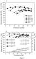
- the conversion rate obtained as a function of the power consumed is represented for each catalytic system according to the invention in Figure 2 (A) .
- Figure 2 (B) as for it represents the selectivity towards methane as a function of the power consumed for each catalyst according to the invention.
- Indium, zinc, sodium, potassium and iron do not provide any improvement in terms of catalytic and energetic performances compared to the control catalyst without promoter.
- the promoters according to the invention make it possible to improve the catalytic performances (conversion rate and selectivity) and energetic performances of the methanation reaction, in particular gadolinium and yttrium.
- the catalytic systems according to the invention have the advantage of a 10-12% gain in the conversion rate compared to existing catalytic systems based on nickel and mixed cerium-zirconium oxide, with a selectivity of up to 100% in methane, at atmospheric pressure and at a temperature between 180 and 230°C, with an energy consumption four times lower.
- Catalytic systems based on CeZr mixed oxide support with 15 wt% nickel relative to the weight of the support and yttrium and/or gadolinium as promoter at different mass contents were tested.
- the mass content is expressed as the weight of promoter relative to the weight of the support.
- Catalytic performance is assessed in particular based on the conversion rate at a reference power of 8 W.
- a +++ catalytic performance corresponds to a CO 2 conversion rate greater than or equal to 75%.
- a ++ catalytic performance corresponds to a CO 2 conversion rate greater than or equal to 60%.
- a + catalytic performance corresponds to a CO 2 conversion rate greater than or equal to 50%.
- a - catalytic performance corresponds to a conversion rate less than 50%.
- a methane selectivity of +++ corresponds to a methane selectivity greater than or equal to 95%.
- a methane selectivity of ++ corresponds to a methane selectivity greater than or equal to 90%.
- a methane selectivity of - corresponds to a methane selectivity less than 90%.
- Energy performance is assessed based on the power consumed to achieve a conversion rate of at least 60%.
- An energy performance rating of +++ corresponds to a power consumption of less than or equal to 6 W.
- An energy performance rating of ++ corresponds to a power consumption of less than or equal to 9 W.
- An energy performance rating of + corresponds to a power consumption of less than or equal to 12 W.
- An energy performance rating of - corresponds to a power consumption of more than 12 W.
- the conversion rate obtained as a function of the power consumed is represented for each yttrium-based catalyst in Table 2 in Figure 3 (A) .
- Figure 3 (B) as for it represents the selectivity towards methane compared to CO as a function of the power consumed for each yttrium-based catalyst.
- the introduction of the promoter improves the catalytic and energetic performances of the reaction compared to the reference catalyst without promoter.
- the best results are obtained with a mass content of 4%.
- the best results are obtained with a mass content of 7%.
- Catalysts outside the invention based on mixed oxide support CeZr, cerium oxide support CeO 2 or zirconium oxide support ZrO 2 with 15% by weight of nickel and 7% by weight of yttrium as promoter weight relative to the weight of the support were tested.
- the control catalytic systems (entries 0, 2 and 4) do not include a promoter.
- the results of their catalytic performance and energy consumption according to the nature of the support in the catalytic system are summarized in Table 3 below.
- Catalytic performance is assessed in particular based on the conversion rate at a reference power of 10 W.
- a +++ catalytic performance corresponds to a CO 2 conversion rate greater than or equal to 75%.
- a ++ catalytic performance corresponds to a CO 2 conversion rate greater than or equal to 60%.
- a + catalytic performance corresponds to a CO 2 conversion rate greater than or equal to 50%.
- a - catalytic performance corresponds to a conversion rate less than 50%.
- a methane selectivity of +++ corresponds to a methane selectivity greater than or equal to 95%.
- a methane selectivity of ++ corresponds to a methane selectivity greater than or equal to 90%.
- a methane selectivity of - corresponds to a methane selectivity less than 90%.
- Energy performance is assessed based on the power consumed to achieve a conversion rate of at least 60%.
- An energy performance rating of +++ corresponds to a power consumption of less than or equal to 6 W.
- An energy performance rating of ++ corresponds to a power consumption of less than or equal to 9 W.
- An energy performance rating of + corresponds to a power consumption of less than or equal to 12 W.
- An energy performance rating of - corresponds to a power consumption of more than 12 W.
- Catalysts based on CeZr mixed oxide support with 15 wt% nickel and 7 wt% yttrium (not the invention) or 4 wt% gadolinium (according to the invention) as promoter weight relative to the weight of the support obtained via different preparation methods were tested.
- Catalytic performance is assessed in particular based on the conversion rate at a reference power of 8 W.
- a +++ catalytic performance corresponds to a CO 2 conversion rate greater than or equal to 75%.
- a ++ catalytic performance corresponds to a CO 2 conversion rate greater than or equal to 60%.
- a + catalytic performance corresponds to a CO 2 conversion rate greater than or equal to 50%.
- a - catalytic performance corresponds to a conversion rate less than 50%.
- a methane selectivity of +++ corresponds to a methane selectivity greater than or equal to 95%.
- a methane selectivity of ++ corresponds to a methane selectivity greater than or equal to 90%.
- a methane selectivity of - corresponds to a methane selectivity less than 90%.
- Energy performance is assessed based on the power consumed to achieve a conversion rate of at least 60%.
- An energy performance rating of +++ corresponds to a power consumption of less than or equal to 6 W.
- An energy performance rating of ++ corresponds to a power consumption of less than or equal to 9 W.
- An energy performance rating of + corresponds to a power consumption of less than or equal to 12 W.
- An energy performance rating of - corresponds to a power consumption of more than 12 W.
Landscapes
- Chemical & Material Sciences (AREA)
- Organic Chemistry (AREA)
- Chemical Kinetics & Catalysis (AREA)
- Engineering & Computer Science (AREA)
- Materials Engineering (AREA)
- Oil, Petroleum & Natural Gas (AREA)
- General Chemical & Material Sciences (AREA)
- Physics & Mathematics (AREA)
- Thermal Sciences (AREA)
- Health & Medical Sciences (AREA)
- General Health & Medical Sciences (AREA)
- Toxicology (AREA)
- Catalysts (AREA)
- Organic Low-Molecular-Weight Compounds And Preparation Thereof (AREA)
Claims (14)
- Verfahren zur Umwandlung eines Gases, das CO2 und/oder CO umfasst, in Gegenwart eines Katalysatorsystems und eines kalten Plasmas, vorzugsweise eines Plasmas, das durch dielektrische Barriereentladung (DBD) erzeugt wird, das Katalysatorsystem umfassend:- ein Träger, der Cerium und/oder Zirkonium umfasst,- Nickel und- ein Vermittler, der unter Gadolinium und den Mischungen Gadolinium und Yttrium ausgewählt wird.
- Verfahren nach Anspruch 1, dadurch gekennzeichnet, dass der Vermittler Gadolinium ist.
- Verfahren nach Anspruch 1 oder 2, dadurch gekennzeichnet, dass es Folgendes erzeugt:- einen oder mehrere Kohlenwasserstoffe, insbesondere Methan, CO, einen oder mehrere Alkohole, Ameisensäure oder Mischungen davon, aus der Umwandlung von CO2,- einen oder mehrere Kohlenwasserstoffe, insbesondere Methan, einen oder mehrere Alkohole, Ameisensäure oder Mischungen davon, aus der Umwandlung von CO.
- Verfahren nach einem der Ansprüche 1 bis 3, dadurch gekennzeichnet, dass es Methan erzeugt.
- Verfahren nach einem der Ansprüche 1 bis 4, dadurch gekennzeichnet, dass das Verfahren in Gegenwart von Diwasserstoff durchgeführt wird.
- Verfahren nach Anspruch 5, dadurch gekennzeichnet, dass das Molverhältnis zwischen CO2 und/oder CO und Diwasserstoff so angepasst ist, dass es Folgendes erzeugt:- einen oder mehrere Kohlenwasserstoffe, insbesondere Methan, CO, einen oder mehrere Alkohole, Ameisensäure oder Mischungen davon, aus der Umwandlung von CO2,- einen oder mehrere Kohlenwasserstoffe, insbesondere Methan, einen oder mehrere Alkohole, Ameisensäure oder Mischungen davon, aus der Umwandlung von CO.
- Verfahren nach Anspruch 5 oder 6, dadurch gekennzeichnet, dass das Verfahren in Gegenwart von CO2 durchgeführt wird und das Molverhältnis CO2/H2 1 beträgt: 4, so dass Methan entsteht.
- Verfahren nach einem der Ansprüche 1 bis 7, dadurch gekennzeichnet, dass der Massengehalt des Vermittlers im Katalysatorsystem von 0,1 Gew.-% bis 20 Gew.-% bezogen auf das Gewicht des Trägers, insbesondere von 0,5 Gew.-% bis 15 Gew.-%, vorzugsweise von 1 Gew.-% bis 10 Gew.-% beträgt.
- Verfahren nach einem der Ansprüche 1 bis 8, dadurch gekennzeichnet, dass der Träger ein Mischoxid aus Cerium und Zirkonium ist.
- Verfahren nach Anspruch 9, dadurch gekennzeichnet, dass das Molverhältnis Cerium/Zirkonium in einem Bereich von 90/10 bis 40/60, vorzugsweise von 80/20 bis 50/50 liegt.
- Verfahren nach einem der Ansprüche 1 bis 10, dadurch gekennzeichnet, dass der Massenanteil an Nickel im Katalysatorsystem bezogen auf das Gewicht des Trägers von 3 bis 30 Gew.-%, vorzugsweise von 7 bis 17 Gew.-%, beträgt.
- Verfahren nach einem der Ansprüche 1 bis 11, dadurch gekennzeichnet, dass der Träger Nickel und der Vermittler ein homogenes Gemisch bilden.
- Katalysatorsystem umfassend:- ein Träger, der Cerium und/oder Zirkonium umfasst,- Nickel und- ein Vermittler, der unter Gadolinium und den Mischungen Gadolinium und Yttrium ausgewählt wird.
- Katalysatorsystem nach Anspruch 13, dadurch gekennzeichnet, dass der Vermittler Gadolinium ist.
Applications Claiming Priority (2)
| Application Number | Priority Date | Filing Date | Title |
|---|---|---|---|
| FR2011113A FR3115711A1 (fr) | 2020-10-29 | 2020-10-29 | Système catalytique mixte pour la conversion du CO2 et/ou du CO dans un procédé hybride plasma froid-catalyse |
| PCT/FR2021/051906 WO2022090671A1 (fr) | 2020-10-29 | 2021-10-29 | Système catalytique mixte pour la conversion du co2 et/ou du co dans un procédé hybride plasma froid-catalyse |
Publications (3)
| Publication Number | Publication Date |
|---|---|
| EP4237140A1 EP4237140A1 (de) | 2023-09-06 |
| EP4237140C0 EP4237140C0 (de) | 2025-03-19 |
| EP4237140B1 true EP4237140B1 (de) | 2025-03-19 |
Family
ID=74860010
Family Applications (1)
| Application Number | Title | Priority Date | Filing Date |
|---|---|---|---|
| EP21810673.0A Active EP4237140B1 (de) | 2020-10-29 | 2021-10-29 | Gemischtes katalytisches system zur umwandlung von co2 und/oder co in einem hybriden kaltplasmakatalyseverfahren |
Country Status (5)
| Country | Link |
|---|---|
| US (1) | US20230390742A1 (de) |
| EP (1) | EP4237140B1 (de) |
| CN (1) | CN116507411A (de) |
| FR (1) | FR3115711A1 (de) |
| WO (1) | WO2022090671A1 (de) |
Families Citing this family (5)
| Publication number | Priority date | Publication date | Assignee | Title |
|---|---|---|---|---|
| FR3115711A1 (fr) | 2020-10-29 | 2022-05-06 | Paris Sciences Et Lettres - Quartier Latin | Système catalytique mixte pour la conversion du CO2 et/ou du CO dans un procédé hybride plasma froid-catalyse |
| FR3137306B1 (fr) * | 2022-06-30 | 2024-07-05 | Suez Int | Procédé de conversion du dioxyde de carbone avec production d’hydrogène, de méthane et/ou d’hydrocarbures |
| CN117299138A (zh) * | 2023-09-12 | 2023-12-29 | 西北大学 | 一种固溶体铜基催化剂及其制备方法和应用 |
| FR3162645A1 (fr) | 2024-05-28 | 2025-12-05 | Ecole Polytechnique | Réacteur et procédé de méthanation catalytique induite par plasma nanoseconde couplé avec un plasma radiofréquence. |
| DE102024129750A1 (de) | 2024-10-14 | 2026-04-16 | enaDyne GmbH | Poröse Glaskeramik für die Umwandlung von Treibhausgasen in einem Kaltplasmakatalyseverfahren |
Family Cites Families (9)
| Publication number | Priority date | Publication date | Assignee | Title |
|---|---|---|---|---|
| FR2989682B1 (fr) * | 2012-04-20 | 2016-01-15 | Rhodia Operations | Procede d'alcanation du co2 utilisant comme catalyseur un compose comprenant du nickel sur un support a base d'oxyde de cerium |
| KR20150028329A (ko) * | 2012-06-29 | 2015-03-13 | 바스프 에스이 | 이리듐-함유 활성 물질의 존재 하에서 탄화수소의 이산화탄소 개질을 위한 고압 공정 |
| CN105817219B (zh) * | 2015-01-04 | 2018-10-16 | 神华集团有限责任公司 | 一种甲烷化催化剂及其制备方法和应用 |
| ES2578704B1 (es) | 2015-01-28 | 2017-05-10 | Université Pierre et Marie Curie | Procedimiento para la reducción de dióxido de carbono a metano mediante catalizador activado por plasma DBD |
| JP6867179B2 (ja) * | 2017-02-01 | 2021-04-28 | 日立造船株式会社 | メタン化反応用触媒の製造方法およびメタンの製造方法 |
| CN109718787B (zh) * | 2017-10-27 | 2022-03-08 | 中国石油化工股份有限公司 | 铈/钇稳定的氧化锆载体及催化剂 |
| FR3090409B1 (fr) * | 2018-12-21 | 2023-04-14 | Paris Sciences Lettres Quartier Latin | Reacteur pour la conversion du dioxyde de carbone |
| CN110433815A (zh) * | 2019-09-02 | 2019-11-12 | 华东理工大学 | 一种二氧化碳甲烷化镍基催化剂及其制备方法和应用 |
| FR3115711A1 (fr) | 2020-10-29 | 2022-05-06 | Paris Sciences Et Lettres - Quartier Latin | Système catalytique mixte pour la conversion du CO2 et/ou du CO dans un procédé hybride plasma froid-catalyse |
-
2020
- 2020-10-29 FR FR2011113A patent/FR3115711A1/fr active Pending
-
2021
- 2021-10-29 US US18/034,647 patent/US20230390742A1/en active Pending
- 2021-10-29 CN CN202180073392.2A patent/CN116507411A/zh active Pending
- 2021-10-29 EP EP21810673.0A patent/EP4237140B1/de active Active
- 2021-10-29 WO PCT/FR2021/051906 patent/WO2022090671A1/fr not_active Ceased
Also Published As
| Publication number | Publication date |
|---|---|
| CN116507411A (zh) | 2023-07-28 |
| WO2022090671A1 (fr) | 2022-05-05 |
| EP4237140C0 (de) | 2025-03-19 |
| US20230390742A1 (en) | 2023-12-07 |
| EP4237140A1 (de) | 2023-09-06 |
| FR3115711A1 (fr) | 2022-05-06 |
Similar Documents
| Publication | Publication Date | Title |
|---|---|---|
| EP4237140B1 (de) | Gemischtes katalytisches system zur umwandlung von co2 und/oder co in einem hybriden kaltplasmakatalyseverfahren | |
| Borchert et al. | Electronic and chemical properties of nanostructured cerium dioxide doped with praseodymium | |
| Cross et al. | Combustion synthesis of a nickel supported catalyst: effect of metal distribution on the activity during ethanol decomposition | |
| Gaudillere et al. | YSZ monoliths promoted with Co as catalysts for the production of H2 by steam reforming of ethanol | |
| Sekine et al. | Reaction mechanism of low-temperature catalysis by surface protonics in an electric field | |
| JP6725994B2 (ja) | 水蒸気改質触媒、それを用いた水蒸気改質方法、及び水蒸気改質反応装置 | |
| JP7515392B2 (ja) | Co2メタネーション触媒及びその製造方法とメタンの製造方法 | |
| CA2817684A1 (fr) | Procede de preparation d'un catalyseur mettant en oeuvre une etape de sechage rapide et son utilisation pour la synthese fischer-tropsch | |
| Shao et al. | Cerium oxide-based catalyst for low-temperature and efficient ammonia decomposition for hydrogen production research | |
| Tao et al. | Sol–gel auto-combustion synthesis of Ni–Ce x Zr 1− x O 2 catalysts for carbon dioxide reforming of methane | |
| Shiwei et al. | Performance of Cu-Mn-Zn/ZrO2 catalysts for methanol synthesis from CO2 hydrogenation: The effect of Zn content | |
| EP4489906A1 (de) | Verfahren und katalysatoren zur plasmakatalytischen reformierung von methan | |
| JP3215680B1 (ja) | 水素ガス中のco除去用触媒 | |
| Piazzolla et al. | Exsolution of Ni nanoparticles from La0. 4Sr0. 4Ti0. 8Ni0. 2O3-δ perovskite for ethanol steam reforming | |
| JP2004196646A (ja) | 燃料改質装置 | |
| Hayashi et al. | Catalytic performance of mesoporous silica-covered nickel core–shell particles for selective CO methanation | |
| JP6081445B2 (ja) | 水素発生用触媒、水素発生用触媒の製造方法、及びこの触媒を用いた水素含有ガスの製造方法、水素発生装置、燃料電池システム、並びに珪素担持CeZr系酸化物 | |
| Patricio et al. | Assembling bifunctional ceria-zirconia electrocatalyst for efficient electrochemical conversion of methane at room temperature | |
| WO2023170562A1 (fr) | Procédé et catalyseur pour la production d'hydrogène par décomposition de l'ammoniac en plasma catalyse | |
| WO2025082764A1 (fr) | Conversion du co2 en presence d'un catalyseur de nickel et de cuivre | |
| EP3651898A1 (de) | Katalysatoren auf basis von pd/ceo2 und herstellungsverfahren dafür | |
| JP2002137901A (ja) | 水素発生方法及び水素発生装置 | |
| JP2002153760A (ja) | 複合触媒、その製造方法、並びにそれを用いた水素発生方法及びガス浄化方法 | |
| JP2026506458A (ja) | プラズマ触媒作用によるガスから水への変換の逆反応 | |
| FR3137310A1 (fr) | Système catalytique pour la production d’hydrogène par décomposition de l’ammoniac en plasma catalyse |
Legal Events
| Date | Code | Title | Description |
|---|---|---|---|
| STAA | Information on the status of an ep patent application or granted ep patent |
Free format text: STATUS: UNKNOWN |
|
| STAA | Information on the status of an ep patent application or granted ep patent |
Free format text: STATUS: THE INTERNATIONAL PUBLICATION HAS BEEN MADE |
|
| PUAI | Public reference made under article 153(3) epc to a published international application that has entered the european phase |
Free format text: ORIGINAL CODE: 0009012 |
|
| STAA | Information on the status of an ep patent application or granted ep patent |
Free format text: STATUS: REQUEST FOR EXAMINATION WAS MADE |
|
| 17P | Request for examination filed |
Effective date: 20230419 |
|
| AK | Designated contracting states |
Kind code of ref document: A1 Designated state(s): AL AT BE BG CH CY CZ DE DK EE ES FI FR GB GR HR HU IE IS IT LI LT LU LV MC MK MT NL NO PL PT RO RS SE SI SK SM TR |
|
| TPAC | Observations filed by third parties |
Free format text: ORIGINAL CODE: EPIDOSNTIPA |
|
| DAV | Request for validation of the european patent (deleted) | ||
| DAX | Request for extension of the european patent (deleted) | ||
| STAA | Information on the status of an ep patent application or granted ep patent |
Free format text: STATUS: EXAMINATION IS IN PROGRESS |
|
| 17Q | First examination report despatched |
Effective date: 20240322 |
|
| GRAP | Despatch of communication of intention to grant a patent |
Free format text: ORIGINAL CODE: EPIDOSNIGR1 |
|
| STAA | Information on the status of an ep patent application or granted ep patent |
Free format text: STATUS: GRANT OF PATENT IS INTENDED |
|
| GRAS | Grant fee paid |
Free format text: ORIGINAL CODE: EPIDOSNIGR3 |
|
| INTG | Intention to grant announced |
Effective date: 20250109 |
|
| GRAA | (expected) grant |
Free format text: ORIGINAL CODE: 0009210 |
|
| STAA | Information on the status of an ep patent application or granted ep patent |
Free format text: STATUS: THE PATENT HAS BEEN GRANTED |
|
| AK | Designated contracting states |
Kind code of ref document: B1 Designated state(s): AL AT BE BG CH CY CZ DE DK EE ES FI FR GB GR HR HU IE IS IT LI LT LU LV MC MK MT NL NO PL PT RO RS SE SI SK SM TR |
|
| REG | Reference to a national code |
Ref country code: GB Ref legal event code: FG4D Free format text: NOT ENGLISH |
|
| REG | Reference to a national code |
Ref country code: CH Ref legal event code: EP |
|
| REG | Reference to a national code |
Ref country code: IE Ref legal event code: FG4D Free format text: LANGUAGE OF EP DOCUMENT: FRENCH |
|
| REG | Reference to a national code |
Ref country code: DE Ref legal event code: R096 Ref document number: 602021027884 Country of ref document: DE |
|
| U01 | Request for unitary effect filed |
Effective date: 20250319 |
|
| U07 | Unitary effect registered |
Designated state(s): AT BE BG DE DK EE FI FR IT LT LU LV MT NL PT RO SE SI Effective date: 20250325 |
|
| PG25 | Lapsed in a contracting state [announced via postgrant information from national office to epo] |
Ref country code: RS Free format text: LAPSE BECAUSE OF FAILURE TO SUBMIT A TRANSLATION OF THE DESCRIPTION OR TO PAY THE FEE WITHIN THE PRESCRIBED TIME-LIMIT Effective date: 20250619 |
|
| PG25 | Lapsed in a contracting state [announced via postgrant information from national office to epo] |
Ref country code: NO Free format text: LAPSE BECAUSE OF FAILURE TO SUBMIT A TRANSLATION OF THE DESCRIPTION OR TO PAY THE FEE WITHIN THE PRESCRIBED TIME-LIMIT Effective date: 20250619 |
|
| PG25 | Lapsed in a contracting state [announced via postgrant information from national office to epo] |
Ref country code: HR Free format text: LAPSE BECAUSE OF FAILURE TO SUBMIT A TRANSLATION OF THE DESCRIPTION OR TO PAY THE FEE WITHIN THE PRESCRIBED TIME-LIMIT Effective date: 20250319 |
|
| PG25 | Lapsed in a contracting state [announced via postgrant information from national office to epo] |
Ref country code: GR Free format text: LAPSE BECAUSE OF FAILURE TO SUBMIT A TRANSLATION OF THE DESCRIPTION OR TO PAY THE FEE WITHIN THE PRESCRIBED TIME-LIMIT Effective date: 20250620 |
|
| U20 | Renewal fee for the european patent with unitary effect paid |
Year of fee payment: 5 Effective date: 20250825 |
|
| PG25 | Lapsed in a contracting state [announced via postgrant information from national office to epo] |
Ref country code: SM Free format text: LAPSE BECAUSE OF FAILURE TO SUBMIT A TRANSLATION OF THE DESCRIPTION OR TO PAY THE FEE WITHIN THE PRESCRIBED TIME-LIMIT Effective date: 20250319 |
|
| PG25 | Lapsed in a contracting state [announced via postgrant information from national office to epo] |
Ref country code: ES Free format text: LAPSE BECAUSE OF FAILURE TO SUBMIT A TRANSLATION OF THE DESCRIPTION OR TO PAY THE FEE WITHIN THE PRESCRIBED TIME-LIMIT Effective date: 20250319 |
|
| PG25 | Lapsed in a contracting state [announced via postgrant information from national office to epo] |
Ref country code: PL Free format text: LAPSE BECAUSE OF FAILURE TO SUBMIT A TRANSLATION OF THE DESCRIPTION OR TO PAY THE FEE WITHIN THE PRESCRIBED TIME-LIMIT Effective date: 20250319 |
|
| PG25 | Lapsed in a contracting state [announced via postgrant information from national office to epo] |
Ref country code: CZ Free format text: LAPSE BECAUSE OF FAILURE TO SUBMIT A TRANSLATION OF THE DESCRIPTION OR TO PAY THE FEE WITHIN THE PRESCRIBED TIME-LIMIT Effective date: 20250319 |
|
| PG25 | Lapsed in a contracting state [announced via postgrant information from national office to epo] |
Ref country code: SK Free format text: LAPSE BECAUSE OF FAILURE TO SUBMIT A TRANSLATION OF THE DESCRIPTION OR TO PAY THE FEE WITHIN THE PRESCRIBED TIME-LIMIT Effective date: 20250319 |
|
| PG25 | Lapsed in a contracting state [announced via postgrant information from national office to epo] |
Ref country code: IS Free format text: LAPSE BECAUSE OF FAILURE TO SUBMIT A TRANSLATION OF THE DESCRIPTION OR TO PAY THE FEE WITHIN THE PRESCRIBED TIME-LIMIT Effective date: 20250719 |
|
| PGFP | Annual fee paid to national office [announced via postgrant information from national office to epo] |
Ref country code: GB Payment date: 20251022 Year of fee payment: 5 |
|
| PLBE | No opposition filed within time limit |
Free format text: ORIGINAL CODE: 0009261 |
|
| STAA | Information on the status of an ep patent application or granted ep patent |
Free format text: STATUS: NO OPPOSITION FILED WITHIN TIME LIMIT |
|
| REG | Reference to a national code |
Ref country code: CH Ref legal event code: L10 Free format text: ST27 STATUS EVENT CODE: U-0-0-L10-L00 (AS PROVIDED BY THE NATIONAL OFFICE) Effective date: 20260128 |
|
| 26N | No opposition filed |
Effective date: 20251222 |