EP4236860B1 - Vorrichtung zum formen von zahnausrichtern - Google Patents
Vorrichtung zum formen von zahnausrichtern Download PDFInfo
- Publication number
- EP4236860B1 EP4236860B1 EP21810731.6A EP21810731A EP4236860B1 EP 4236860 B1 EP4236860 B1 EP 4236860B1 EP 21810731 A EP21810731 A EP 21810731A EP 4236860 B1 EP4236860 B1 EP 4236860B1
- Authority
- EP
- European Patent Office
- Prior art keywords
- moulding
- heating
- support
- mounting support
- thermoforming
- Prior art date
- Legal status (The legal status is an assumption and is not a legal conclusion. Google has not performed a legal analysis and makes no representation as to the accuracy of the status listed.)
- Active
Links
Images

Classifications
-
- A—HUMAN NECESSITIES
- A61—MEDICAL OR VETERINARY SCIENCE; HYGIENE
- A61C—DENTISTRY; APPARATUS OR METHODS FOR ORAL OR DENTAL HYGIENE
- A61C7/00—Orthodontics, i.e. obtaining or maintaining the desired position of teeth, e.g. by straightening, evening, regulating, separating, or by correcting malocclusions
- A61C7/08—Mouthpiece-type retainers or positioners, e.g. for both the lower and upper arch
-
- B—PERFORMING OPERATIONS; TRANSPORTING
- B29—WORKING OF PLASTICS; WORKING OF SUBSTANCES IN A PLASTIC STATE IN GENERAL
- B29C—SHAPING OR JOINING OF PLASTICS; SHAPING OF MATERIAL IN A PLASTIC STATE, NOT OTHERWISE PROVIDED FOR; AFTER-TREATMENT OF THE SHAPED PRODUCTS, e.g. REPAIRING
- B29C51/00—Shaping by thermoforming, i.e. shaping sheets or sheet like preforms after heating, e.g. shaping sheets in matched moulds or by deep-drawing; Apparatus therefor
- B29C51/10—Forming by pressure difference, e.g. vacuum
-
- B—PERFORMING OPERATIONS; TRANSPORTING
- B29—WORKING OF PLASTICS; WORKING OF SUBSTANCES IN A PLASTIC STATE IN GENERAL
- B29C—SHAPING OR JOINING OF PLASTICS; SHAPING OF MATERIAL IN A PLASTIC STATE, NOT OTHERWISE PROVIDED FOR; AFTER-TREATMENT OF THE SHAPED PRODUCTS, e.g. REPAIRING
- B29C51/00—Shaping by thermoforming, i.e. shaping sheets or sheet like preforms after heating, e.g. shaping sheets in matched moulds or by deep-drawing; Apparatus therefor
- B29C51/18—Thermoforming apparatus
- B29C51/20—Thermoforming apparatus having movable moulds or mould parts
- B29C51/22—Thermoforming apparatus having movable moulds or mould parts rotatable about an axis
-
- B—PERFORMING OPERATIONS; TRANSPORTING
- B29—WORKING OF PLASTICS; WORKING OF SUBSTANCES IN A PLASTIC STATE IN GENERAL
- B29C—SHAPING OR JOINING OF PLASTICS; SHAPING OF MATERIAL IN A PLASTIC STATE, NOT OTHERWISE PROVIDED FOR; AFTER-TREATMENT OF THE SHAPED PRODUCTS, e.g. REPAIRING
- B29C51/00—Shaping by thermoforming, i.e. shaping sheets or sheet like preforms after heating, e.g. shaping sheets in matched moulds or by deep-drawing; Apparatus therefor
- B29C51/26—Component parts, details or accessories; Auxiliary operations
- B29C51/261—Handling means, e.g. transfer means, feeding means
- B29C51/262—Clamping means for the sheets, e.g. clamping frames
-
- B—PERFORMING OPERATIONS; TRANSPORTING
- B29—WORKING OF PLASTICS; WORKING OF SUBSTANCES IN A PLASTIC STATE IN GENERAL
- B29C—SHAPING OR JOINING OF PLASTICS; SHAPING OF MATERIAL IN A PLASTIC STATE, NOT OTHERWISE PROVIDED FOR; AFTER-TREATMENT OF THE SHAPED PRODUCTS, e.g. REPAIRING
- B29C51/00—Shaping by thermoforming, i.e. shaping sheets or sheet like preforms after heating, e.g. shaping sheets in matched moulds or by deep-drawing; Apparatus therefor
- B29C51/26—Component parts, details or accessories; Auxiliary operations
- B29C51/42—Heating or cooling
- B29C51/421—Heating or cooling of preforms, specially adapted for thermoforming
-
- B—PERFORMING OPERATIONS; TRANSPORTING
- B29—WORKING OF PLASTICS; WORKING OF SUBSTANCES IN A PLASTIC STATE IN GENERAL
- B29C—SHAPING OR JOINING OF PLASTICS; SHAPING OF MATERIAL IN A PLASTIC STATE, NOT OTHERWISE PROVIDED FOR; AFTER-TREATMENT OF THE SHAPED PRODUCTS, e.g. REPAIRING
- B29C51/00—Shaping by thermoforming, i.e. shaping sheets or sheet like preforms after heating, e.g. shaping sheets in matched moulds or by deep-drawing; Apparatus therefor
- B29C51/26—Component parts, details or accessories; Auxiliary operations
- B29C51/46—Measuring, controlling or regulating
-
- B—PERFORMING OPERATIONS; TRANSPORTING
- B29—WORKING OF PLASTICS; WORKING OF SUBSTANCES IN A PLASTIC STATE IN GENERAL
- B29C—SHAPING OR JOINING OF PLASTICS; SHAPING OF MATERIAL IN A PLASTIC STATE, NOT OTHERWISE PROVIDED FOR; AFTER-TREATMENT OF THE SHAPED PRODUCTS, e.g. REPAIRING
- B29C2791/00—Shaping characteristics in general
- B29C2791/004—Shaping under special conditions
- B29C2791/006—Using vacuum
-
- B—PERFORMING OPERATIONS; TRANSPORTING
- B29—WORKING OF PLASTICS; WORKING OF SUBSTANCES IN A PLASTIC STATE IN GENERAL
- B29C—SHAPING OR JOINING OF PLASTICS; SHAPING OF MATERIAL IN A PLASTIC STATE, NOT OTHERWISE PROVIDED FOR; AFTER-TREATMENT OF THE SHAPED PRODUCTS, e.g. REPAIRING
- B29C2791/00—Shaping characteristics in general
- B29C2791/004—Shaping under special conditions
- B29C2791/007—Using fluid under pressure
Definitions
- the present invention relates to an apparatus for the production of movable dental apparatuses.
- the invention relates to an apparatus for thermoforming movable dental apparatuses in which at least one moulding support is present suitable to house a dental arch, a mounting support suitable to house a thermoformable sheet, a heating position in which a heating device for heating the thermoformable sheet is present housed in the relative mounting support and a moulding position in which there is a moulding device suitable to realize together with the moulding support and mounting support a moulding chamber in which the impression and the thermoformable sheet previously heated in the heating position are located and in which a vacuum/overpressure is created to execute the thermoforming of said thermoformable sheet (F).
- at least one moulding support is present suitable to house a dental arch
- a mounting support suitable to house a thermoformable sheet
- a heating position in which a heating device for heating the thermoformable sheet is present housed in the relative mounting support
- a moulding position in which there is a moulding device suitable to realize together with the moulding support and mounting support a moulding chamber in which the impression and the thermoformable sheet previously
- Movable dental apparatuses are functional apparatuses to be applied to the dental arch to correct specific positioning defects.
- the aligners are manufactured with CAM-CAD (Computer-aided manufacturing/Computer-aided design) technology: starting from the plaster impression of the patient's dental arch and then proceeding with a 3D scan of the same in order to digitize the geometry and obtain virtual 3D models. Subsequently, through the use of CAD software, the corrective stages of the malocclusion and the physical models of the arches for each of the corrective stages are reproduced. Based on these physical models, a series of aligners necessary to satisfy the intended treatment is moulded. In fact, the treatment with invisible aligners is based on the sequential use of aligners, realized with transparent thermoplastic material and characterized by appropriate geometry. A certain number of aligners must therefore be made for each patient.
- CAM-CAD Computer-aided manufacturing/Computer-aided design
- the aligners are made of a thermoformable material such as polypropylene (PP), polycarbonate (PC), polyethylene terephthalate glycol (PETG) or thermoplastic polyurethane (TPU), by means of a thermoforming apparatus.
- PP polypropylene
- PC polycarbonate
- PETG polyethylene terephthalate glycol
- TPU thermoplastic polyurethane
- An apparatus for thermoforming dental aligners conventionally comprises a moulding support on which the dental arch is rested, a mounting support in which the thermoformable disc is housed, a heating head in which the thermoformable disc is heated to soften and a moulding moulding head in which a moulding chamber is created in which the dental arch and the softened disc superimposed thereon are located and in which a vacuum or overpressure is created to cause the disc to copy the shape of the impression.
- these apparatuses comprise a single working head in which the heating station and the moulding station are present and a mounting support which contains the thermoformable disc is manually fed first to the heating station and then moved, again manually, to the moulding station, in which the dental arch to be copied is arranged, also in this case manually.
- Apparatuses as outlined above are, for example, those covered by European patent EP 1 905 380 B1 and German patent DE10307688 .
- the high operator time required is a very significant limitation since, as previously highlighted, each individual treatment requires the production of a multiplicity of aligners. In fact, the analysis of the required operator time showed that the operator must always remain close to the machine to reload the disc and dental arch when the cycle is finished.
- the type with automatic movement is more advantageous because it does not require the intermediate operation of the operator to move the heated disc from the heating zone to the moulding zone.
- the operator time for each aligner produced is estimated at approximately 180 seconds of machine operation in the manual type, to which are added approximately 20 seconds of loading and unloading the disc and dental arch.
- the operator time for the automatic type is comparable to the previous one if the machine must continuously produce a number of aligners. In fact, by producing one aligner at a time, despite being automated from heating to moulding, the operator must still load one set at a time at the end of a cycle.
- Apparatuses capable of producing multiple aligners at the same time are also known, thus reducing the operator time required to make a number of aligners.
- This category includes apparatuses having a single moulding head of increased size in which more than one dental impression may be housed at the same time and a moulding disc of increased size.
- the operator times are obviously reduced and however the aligners produced with this type of apparatus are judged of poor quality because the presence of several dental impressions (up to 9) on which a single thermoformable material disc is thermoformed results in an incorrect stretching of the disc heated on the impression and therefore in an inadequate quality of the final product.
- apparatuses comprising a plurality of heating heads and as many moulding heads for simultaneously thermoforming a plurality of aligners.
- An apparatus of this type is described for example in US 20170144360 which provides a vacuum plate to which are associated a plurality of supports suitable to house dental impressions arranged in succession.
- the thermoformable material in the form of a continuous strip is fed to extend over the plate over which there is a heating head with a plurality of heating elements movable over the plate between a waiting position and a heating position.
- a plurality of aligners can be made simultaneously.
- this apparatus there is a single thermoformable sheet, thus it has the same limits as the system with enlarged head previously described.
- thermoformable disc From EP 1 905 380 the possibility of measuring the temperature reached by the thermoformable disc by means of an infrared sensor is also known. However, this involves the heating term being defined based on the achievement of a certain temperature.
- the infrared sensor has on the one hand a high cost, and also performs a reading that is not always precise both because the thermoformable disc has high radial thermal gradients and because this measurement can be influenced by the presence of the heating element present above.
- the object of the present invention is to propose an apparatus for the thermoforming of dental aligners capable of exceeding the limits of the prior art highlighted above, in particular with regard to the operator time necessary to realize an entire set of aligners.
- Another object of the present invention is to propose an apparatus for the thermoforming of dental aligners that has a high productivity, both by virtue of the reduced operator times, and for a drastic reduction of the moulding time.
- Another object of the present invention is to propose an apparatus for thermoforming aligners in which the heating head is optimized in particular to ensure that the thermoformable disc is optimally heated.
- an apparatus for the thermoforming of dental aligners comprises a support structure suitable to house a plurality of moulding supports each suitable to house at least one dental arch, a mounting support suitable to house a thermoformable sheet and a relative retaining ring element, a heating device for heating a thermoformable sheet housed in said mounting support and a moulding device suitable to realize together with said moulding support and mounting support a moulding chamber, said moulding device being suitable to realize a vacuum/overpressure in said moulding chamber for executing the thermoforming of said thermoformable sheet, said mounting support being movable at least between a heating position in which it is associated with said heating device and a moulding position in which it is associated with said moulding device.
- each of said moulding supports of the apparatus are associated a relative mounting support and retaining ring element in an operating module, a plurality of operating modules being arranged at an angle equidistant on a rotary table of said support structure, said rotary table being operated in rotation in discrete steps to bring each of said operating modules in succession, first at said heating position and subsequently at said moulding position.
- the apparatus of the invention allows to simultaneously load a plurality of sets for realizing as many dental impressions, thus allowing the operator to not man the apparatus for the entire processing period until all the aligners have been made.
- the heating device comprises at least one contactless sensor arranged to detect a certain amount of deformation of said thermoformable sheet as a result of the softening to which it is subject due to the heating, a control unit of said apparatus being configured to determine the interruption of a heating step in said heating position as a function of the information received from said contactless sensor.
- the contactless sensor detects the extent of deformation undergone by the thermoformable disc as a result of its softening and thus allows to directly determine when the degree of softening achieved is ideal for the subsequent moulding operation.
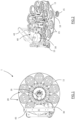
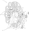
- an apparatus for thermoforming dental aligners is indicated as a whole with 1, which comprises a support structure, 10, provided with feet, 15, on which a rotary table, 11, centrally hinged to the support structure 10 and operated in rotation with respect to its vertical barycentral axis by means of a gear motor, 16, housed on the support structure 10 near the rotation axis of the table 11 and electronically controlled.
- rotary table 11 On the rotary table 11 are arranged at an angle equidistant from each other a plurality of operating modules, 20, which in this embodiment are ten in number.
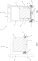
- each operating module 20 comprises: a moulding support, 21, permanently anchored to the rotary table 11 and arranged to receive at least one dental arch, I; a vertical slide, 24 to which a mounting support, 22 is slidably associated; a return element, 25 consisting in this embodiment of a spring, suitable to push the mounting support 22 upwards; and a locking/unlocking mechanism , 26, which keeps the mounting support 22 locked in a lowered moulding position, PA, when the latter is pushed downwards and which selectively releases it to allow it to return to a raised position, PS.
- the reference element may be of a magnetic type and the locking/unlocking mechanism 26 may not be present in this case.
- the mounting support 22, movable above the moulding support 21, is suitable to house a thermoformable disc, F, and a retaining ring, 23, which keeps the disc F in position once inserted into the mounting support 22.
- a heating device 30 is mounted at a position which each operating group 20 can assume following the rotation of the rotary table 11, called the heating position, PR.
- the heating device 30 provides a heating head, 32, mounted above the raised position PS of the mounting support 22, by means of a column, 33, stably associated with the support structure 10.
- An arm, 34 arranged at an adjustable height along the column 33, carries a contactless sensor, 31, arranged below the mounting support 22 near the latter.
- the contactless sensor 31 is advantageously a horizontally arranged optical sensor for measuring the vertical deformation of the heated thermoformable disc F.
- the disc F softens moulding, due to the force of gravity, a sort of bubble extending downwards with respect to the relative initial lying plane.
- the bubble reaches the height at which the sensor 31 is positioned, it is detected by the sensor and consequently a control unit of the apparatus interrupts the heating step.
- each operating group 20 can assume following the rotation of the rotary table 11, called the moulding position, PF, a moulding device 40 is mounted.
- the moulding device 40 comprises a cylinder, 47, with a piston, 42, which actuated downwards presses on the retaining ring 23 bringing the mounting support 22 in its lowered position in abutment on the moulding support 21.
- the moulding support 21, the mounting support 22 and the piston 42 define a sealed moulding chamber 41.
- at least one inlet pipe 45 is provided for bringing a fluid to the moulding chamber so as to put pressure on the latter so that during a moulding time the disc F is pushed to copy the shape of the dental arch I.
- the moulding device 40 comprises an outlet pipe, 46, communicating with the moulding chamber 41 to allow the expulsion of gas from said moulding chamber 41.
- the outlet pipe 46 is arranged to remain at least partially open during the application of the moulding pressure, so that during the application of said moulding pressure there is a gas circulation from the inlet pipe 45 to the moulding chamber (41) and then to the outlet pipe 46 to be expelled outside the moulding device. This makes it possible to significantly reduce the moulding time and therefore increase the productivity of the apparatus since the gas circulation in the moulding chamber 41 allows a high heat removal and therefore a much faster cooling of the thermoformable material.
- the outlet pipe 46 is obviously calibrated in size to allow the flow of gas without causing significant pressure losses in the moulding chamber 41. Alternatively, the pipe 46 may be opened with a certain delay with respect to the closure of the moulding chamber 41 and the realization of the overpressure therein.
- the moulding device 40 is mounted on a self-supporting structure, 43, associated with the support structure 10 and which provides a striker element, 44, arranged below in contact with said rotary table 11 during the downward pressure operation of the piston 42 so that the pressure exerted by said piston 42 is supported by said striker element 44 instead of by the rotary table 11.
- a self-supporting structure, 43 associated with the support structure 10 and which provides a striker element, 44, arranged below in contact with said rotary table 11 during the downward pressure operation of the piston 42 so that the pressure exerted by said piston 42 is supported by said striker element 44 instead of by the rotary table 11.
- the apparatus 1 is obviously provided with an appropriate casing, not shown in the figures, which completely prevents access during operation.
- the casing can be removed or provides an access door to allow loading all the operating modules 20 with the necessary dental impressions I and thermoformable discs F, after which the access is closed and the apparatus 1 is started to operate autonomously until all the loaded operating modules 20 have been processed. This allows an operator to engage in other activities while the apparatus produces a number of aligners even equal to the number of operating modules 20 with which the apparatus is provided.
- a permanent access position can be provided, on a side opposite to that where the heating device 30 and the moulding device 40 are located, to allow the transiting operating module to be unloaded and loaded at the aforementioned access position, so that the apparatus, manned by an operator, can work in a continuous cycle without interruptions.
Landscapes
- Engineering & Computer Science (AREA)
- Mechanical Engineering (AREA)
- Health & Medical Sciences (AREA)
- Oral & Maxillofacial Surgery (AREA)
- Dentistry (AREA)
- Epidemiology (AREA)
- Life Sciences & Earth Sciences (AREA)
- Animal Behavior & Ethology (AREA)
- General Health & Medical Sciences (AREA)
- Public Health (AREA)
- Veterinary Medicine (AREA)
- Dental Tools And Instruments Or Auxiliary Dental Instruments (AREA)
Claims (6)
- Vorrichtung (1) zum Warmformen von Zahnausrichtern, wobei die Vorrichtung (1) eine Trägerstruktur (10), die eine Vielzahl von Formträgern (21) aufnimmt, von denen jeder geeignet ist, mindestens einen Zahnbogen (I) aufzunehmen, eine Vielzahl von Montageträgern (22), die jeweils ein entsprechendes Halteringelement (23) aufweisen, das geeignet ist, eine thermoformbare Platte (F) aufzunehmen und zu halten, eine Heizvorrichtung (30) zum Erwärmen einer thermoformbaren Platte (F), die zur Aufnahme in der Halterung (22) geeignet ist, und eine Formvorrichtung (40), die geeignet ist, zusammen mit dem Formträger (21) und dem Montageträger (22) eine Formkammer (41) zu bilden, umfasst, wobei die Formvorrichtung (40) geeignet ist, ein Vakuum/einen Überdruck in der Formkammer (41) zu erzeugen, um das Thermoformen der thermoformbaren Folie (F) auszuführen, und der Montageträger (22) zumindest zwischen einer Heizposition (PR), in der er mit der Heizvorrichtung (30) verbunden ist, und einer Formposition (PF), in der er mit der Formanlage (40) verbunden ist, beweglich ist, wobei die Vorrichtung (1) dadurch gekennzeichnet ist, dass jeder der Formträger (21) mit einem entsprechenden der Montageträger (22) und einem entsprechenden der ringförmigen Halteelemente (23) in einem Betriebsmodul (20) verbunden ist, und, dass eine Vielzahl von Arbeitsmodulen (20), die in einem äquidistanten Winkel auf einem Drehtisch (11) der Trägerstruktur (10) angeordnet sind, wobei der Drehtisch (11) in diskreten Schritten in Drehung versetzt wird, um jedes der Arbeitsmodule (20) nacheinander zunächst in die Heizposition (PR) und dann in die Formposition (PF) zu bringen.
- Vorrichtung (1) zum Warmformen von Zahnausrichtern nach Anspruch 1, dadurch gekennzeichnet, dass die Heizvorrichtung (30) mindestens einen berührungslosen Sensor (31) umfasst, der so beschaffen ist, dass er ein bestimmtes Maß an Verformung der thermoformbaren Folie (F) infolge der Erweichung, der sie aufgrund der Erwärmung unterliegt, erfasst, wobei eine Steuereinheit der Vorrichtung (1) so konfiguriert ist, dass sie die Unterbrechung eines Heizschritts in der Heizposition (PR) in Abhängigkeit von der von dem berührungslosen Sensor (31) empfangenen Information bestimmt.
- Vorrichtung zum Warmformen von Zahnausrichtern nach Anspruch 1 oder 2, dadurch gekennzeichnet, dass der Formträger (21) in dem Betriebsmodul (20) auf dem Drehtisch (11) angeordnet ist und der Montageträger (22) oberhalb des entsprechenden Formträgers (21) zumindest zwischen einer angehobenen Ladeposition (PS) und einer abgesenkten Formposition (PA), in der der Montageträger (22) an dem Formträger (21) anliegt, bewegbar ist, und dass die Formvorrichtung (40) einen Kolben (42) umfasst, der geeignet ist, von oben an der Halterung (22) und dem Halteelement (23) anzuliegen, um sie in Richtung der abgesenkten Formposition (PA) zu schieben, um die Formkammer (41) zu realisieren und einen geeigneten Formdruck anzuwenden, um die Formkammer (41) abzudichten, und dass der Kolben (42) auf einer selbsttragenden Struktur (43) montiert ist, die ein Anschlagelement (44) vorsieht, das während des Betriebs des Kolbens (42) unten in Kontakt mit dem Drehtisch (11) angeordnet ist, so dass der durch den Kolben (42) ausgeübte Druck durch das Anschlagelement (44) anstelle des Drehtischs (11) getragen wird.
- Vorrichtung (1) zum Warmverformen von Zahnschienen nach dem vorhergehenden Anspruch, dadurch gekennzeichnet, dass das Arbeitsmodul (20) umfasst: einen vertikalen Schlitten (24), mit dem der Montageträger (22) gleitend verbunden ist; und Rückstellelemente (25), die geeignet sind, den Montageträger (22) nach oben zu schieben.
- Vorrichtung (1) zum Thermoformen von Zahnspangen nach dem vorhergehenden Anspruch, dadurch gekennzeichnet, dass das Arbeitsmodul (20) einen Verriegelungs-/Entriegelungsmechanismus (26) aufweist, der selektiv geeignet ist, um in der abgesenkten Formposition (PA) verriegelt zu bleiben oder die Bewegung entlang des vertikalen Schlittens (24) des Montageträgers (22) zu ermöglichen, wobei die Rückstellelemente (25) aus elastischen Elementen bestehen.
- Vorrichtung (1) zum Warmformen von Zahnausrichtern nach einem der vorhergehenden Ansprüche, dadurch gekennzeichnet, dass die Formvorrichtung (40) Druckmittel umfasst, die geeignet sind, die Formkammer (41) durch Gasinjektion unter Druck zu setzen, wobei die Druckmittel mindestens ein Einlassrohr (45) umfassen, um die Injektion von Gas in die Formkammer (41) zu ermöglichen, und die Druckeinrichtung mindestens ein Auslassrohr (46) umfasst, um das Ausstoßen von Gas aus der Formkammer (41) zu ermöglichen, wobei das Auslassrohr (46) so angeordnet ist, dass es während der Anwendung eines Formdrucks zumindest teilweise offen bleibt, so dass während der Anwendung des Formdrucks eine Gaszirkulation von dem Einlassrohr (45) zu der Formkammer (41) und daher zu dem Auslassrohr (46) stattfindet.
Applications Claiming Priority (2)
| Application Number | Priority Date | Filing Date | Title |
|---|---|---|---|
| IT202000025858 | 2020-10-30 | ||
| PCT/IB2021/060041 WO2022091027A1 (en) | 2020-10-30 | 2021-10-29 | Apparatus for moulding dental aligners |
Publications (3)
| Publication Number | Publication Date |
|---|---|
| EP4236860A1 EP4236860A1 (de) | 2023-09-06 |
| EP4236860C0 EP4236860C0 (de) | 2024-12-11 |
| EP4236860B1 true EP4236860B1 (de) | 2024-12-11 |
Family
ID=74184794
Family Applications (1)
| Application Number | Title | Priority Date | Filing Date |
|---|---|---|---|
| EP21810731.6A Active EP4236860B1 (de) | 2020-10-30 | 2021-10-29 | Vorrichtung zum formen von zahnausrichtern |
Country Status (4)
| Country | Link |
|---|---|
| US (1) | US12472036B2 (de) |
| EP (1) | EP4236860B1 (de) |
| CN (1) | CN116472006A (de) |
| WO (1) | WO2022091027A1 (de) |
Families Citing this family (3)
| Publication number | Priority date | Publication date | Assignee | Title |
|---|---|---|---|---|
| US20200290262A1 (en) * | 2019-03-15 | 2020-09-17 | Align Technology, Inc. | Thermoforming multiple aligners in parallel |
| EP4355256B1 (de) * | 2021-06-14 | 2026-04-08 | Align Technology, Inc. | Dynamische thermoformung von dentalvorrichtungen |
| US11897181B2 (en) | 2021-06-14 | 2024-02-13 | Align Technology, Inc. | Dynamic thermoforming of dental appliances |
Family Cites Families (5)
| Publication number | Priority date | Publication date | Assignee | Title |
|---|---|---|---|---|
| DE10307688B4 (de) | 2003-02-21 | 2005-06-16 | Scheu-Dental Gmbh | Druckformgerät |
| US7261533B2 (en) * | 2003-10-21 | 2007-08-28 | Align Technology, Inc. | Method and apparatus for manufacturing dental aligners |
| ES2318640T3 (es) | 2006-09-28 | 2009-05-01 | Erkodent Erich Kopp Gmbh | Aparato dental de conformado por presion y procedimiento de operacion. |
| US10286594B2 (en) | 2015-11-25 | 2019-05-14 | Clearcorrect Operating, Llc | Batch thermoformer for dental appliances |
| US20200290262A1 (en) * | 2019-03-15 | 2020-09-17 | Align Technology, Inc. | Thermoforming multiple aligners in parallel |
-
2021
- 2021-10-29 CN CN202180073631.4A patent/CN116472006A/zh active Pending
- 2021-10-29 EP EP21810731.6A patent/EP4236860B1/de active Active
- 2021-10-29 US US18/034,470 patent/US12472036B2/en active Active
- 2021-10-29 WO PCT/IB2021/060041 patent/WO2022091027A1/en not_active Ceased
Also Published As
| Publication number | Publication date |
|---|---|
| EP4236860C0 (de) | 2024-12-11 |
| US20250073001A1 (en) | 2025-03-06 |
| US12472036B2 (en) | 2025-11-18 |
| WO2022091027A1 (en) | 2022-05-05 |
| EP4236860A1 (de) | 2023-09-06 |
| CN116472006A (zh) | 2023-07-21 |
Similar Documents
| Publication | Publication Date | Title |
|---|---|---|
| US12472036B2 (en) | Apparatus for molding dental aligners | |
| US6197227B1 (en) | Toric axis alignment machine and method | |
| US5658523A (en) | Method and apparatus for forming twin sheet hollow plastic articles | |
| EP0516871B1 (de) | Vorrichtung und Verfahren zur Herstellung einer Spritze | |
| US4796408A (en) | Method and apparatus for vacuum packaging | |
| CN110451786B (zh) | 一种热弯加工设备及加工3d曲面玻璃盖板的方法 | |
| CZ288093B6 (cs) | Způsob a zařízení pro ohýbání plošného skleněného dílce | |
| KR20070010006A (ko) | 용기 성형 | |
| JP7141526B2 (ja) | カップを処理するための装置および方法 | |
| US20170144360A1 (en) | Batch Thermoformer for Dental Appliances | |
| JP3391737B2 (ja) | ゴム加硫プレス装置 | |
| US20060113715A1 (en) | Device and method for thermoforming an object having a back draft portion | |
| KR20060046594A (ko) | 열간 프레스 장치 및 방법 | |
| EP1697111B1 (de) | Verfahren zur handhabung einer ophthalmischen linse | |
| CN115195023A (zh) | 一种热塑性有机纤维板一体成型设备 | |
| JP7345946B1 (ja) | 熱成形装置 | |
| JPH0976338A (ja) | プリフォームの温調装置およびそれを用いたブロー成形方法 | |
| JP7345945B1 (ja) | 熱成形装置 | |
| JP3391739B2 (ja) | ゴム加硫プレス装置 | |
| JP3391738B2 (ja) | ゴム加硫プレス装置 | |
| CN112276547A (zh) | 自动装配plc系统 | |
| GB2218666A (en) | Sheet forming | |
| JPH07285181A (ja) | 樹脂製ピースの結晶化方法および装置 | |
| WO2020090766A1 (ja) | 積層パン生地の成形方法および成形装置 | |
| JPH06210642A (ja) | 光学素子の成形装置 |
Legal Events
| Date | Code | Title | Description |
|---|---|---|---|
| STAA | Information on the status of an ep patent application or granted ep patent |
Free format text: STATUS: UNKNOWN |
|
| STAA | Information on the status of an ep patent application or granted ep patent |
Free format text: STATUS: THE INTERNATIONAL PUBLICATION HAS BEEN MADE |
|
| PUAI | Public reference made under article 153(3) epc to a published international application that has entered the european phase |
Free format text: ORIGINAL CODE: 0009012 |
|
| STAA | Information on the status of an ep patent application or granted ep patent |
Free format text: STATUS: REQUEST FOR EXAMINATION WAS MADE |
|
| 17P | Request for examination filed |
Effective date: 20230515 |
|
| AK | Designated contracting states |
Kind code of ref document: A1 Designated state(s): AL AT BE BG CH CY CZ DE DK EE ES FI FR GB GR HR HU IE IS IT LI LT LU LV MC MK MT NL NO PL PT RO RS SE SI SK SM TR |
|
| DAV | Request for validation of the european patent (deleted) | ||
| DAX | Request for extension of the european patent (deleted) | ||
| GRAP | Despatch of communication of intention to grant a patent |
Free format text: ORIGINAL CODE: EPIDOSNIGR1 |
|
| STAA | Information on the status of an ep patent application or granted ep patent |
Free format text: STATUS: GRANT OF PATENT IS INTENDED |
|
| INTG | Intention to grant announced |
Effective date: 20240321 |
|
| GRAS | Grant fee paid |
Free format text: ORIGINAL CODE: EPIDOSNIGR3 |
|
| GRAA | (expected) grant |
Free format text: ORIGINAL CODE: 0009210 |
|
| STAA | Information on the status of an ep patent application or granted ep patent |
Free format text: STATUS: THE PATENT HAS BEEN GRANTED |
|
| AK | Designated contracting states |
Kind code of ref document: B1 Designated state(s): AL AT BE BG CH CY CZ DE DK EE ES FI FR GB GR HR HU IE IS IT LI LT LU LV MC MK MT NL NO PL PT RO RS SE SI SK SM TR |
|
| REG | Reference to a national code |
Ref country code: GB Ref legal event code: FG4D |
|
| REG | Reference to a national code |
Ref country code: CH Ref legal event code: EP |
|
| REG | Reference to a national code |
Ref country code: DE Ref legal event code: R096 Ref document number: 602021023361 Country of ref document: DE |
|
| REG | Reference to a national code |
Ref country code: IE Ref legal event code: FG4D |
|
| U01 | Request for unitary effect filed |
Effective date: 20250110 |
|
| U07 | Unitary effect registered |
Designated state(s): AT BE BG DE DK EE FI FR IT LT LU LV MT NL PT RO SE SI Effective date: 20250117 |
|
| PG25 | Lapsed in a contracting state [announced via postgrant information from national office to epo] |
Ref country code: HR Free format text: LAPSE BECAUSE OF FAILURE TO SUBMIT A TRANSLATION OF THE DESCRIPTION OR TO PAY THE FEE WITHIN THE PRESCRIBED TIME-LIMIT Effective date: 20241211 |
|
| PG25 | Lapsed in a contracting state [announced via postgrant information from national office to epo] |
Ref country code: ES Free format text: LAPSE BECAUSE OF FAILURE TO SUBMIT A TRANSLATION OF THE DESCRIPTION OR TO PAY THE FEE WITHIN THE PRESCRIBED TIME-LIMIT Effective date: 20241211 |
|
| PG25 | Lapsed in a contracting state [announced via postgrant information from national office to epo] |
Ref country code: NO Free format text: LAPSE BECAUSE OF FAILURE TO SUBMIT A TRANSLATION OF THE DESCRIPTION OR TO PAY THE FEE WITHIN THE PRESCRIBED TIME-LIMIT Effective date: 20250311 |
|
| PG25 | Lapsed in a contracting state [announced via postgrant information from national office to epo] |
Ref country code: GR Free format text: LAPSE BECAUSE OF FAILURE TO SUBMIT A TRANSLATION OF THE DESCRIPTION OR TO PAY THE FEE WITHIN THE PRESCRIBED TIME-LIMIT Effective date: 20250312 |
|
| PG25 | Lapsed in a contracting state [announced via postgrant information from national office to epo] |
Ref country code: RS Free format text: LAPSE BECAUSE OF FAILURE TO SUBMIT A TRANSLATION OF THE DESCRIPTION OR TO PAY THE FEE WITHIN THE PRESCRIBED TIME-LIMIT Effective date: 20250311 |
|
| PG25 | Lapsed in a contracting state [announced via postgrant information from national office to epo] |
Ref country code: SM Free format text: LAPSE BECAUSE OF FAILURE TO SUBMIT A TRANSLATION OF THE DESCRIPTION OR TO PAY THE FEE WITHIN THE PRESCRIBED TIME-LIMIT Effective date: 20241211 |
|
| PG25 | Lapsed in a contracting state [announced via postgrant information from national office to epo] |
Ref country code: PL Free format text: LAPSE BECAUSE OF FAILURE TO SUBMIT A TRANSLATION OF THE DESCRIPTION OR TO PAY THE FEE WITHIN THE PRESCRIBED TIME-LIMIT Effective date: 20241211 |
|
| PG25 | Lapsed in a contracting state [announced via postgrant information from national office to epo] |
Ref country code: IS Free format text: LAPSE BECAUSE OF FAILURE TO SUBMIT A TRANSLATION OF THE DESCRIPTION OR TO PAY THE FEE WITHIN THE PRESCRIBED TIME-LIMIT Effective date: 20250411 |
|
| PG25 | Lapsed in a contracting state [announced via postgrant information from national office to epo] |
Ref country code: SK Free format text: LAPSE BECAUSE OF FAILURE TO SUBMIT A TRANSLATION OF THE DESCRIPTION OR TO PAY THE FEE WITHIN THE PRESCRIBED TIME-LIMIT Effective date: 20241211 |
|
| PG25 | Lapsed in a contracting state [announced via postgrant information from national office to epo] |
Ref country code: CZ Free format text: LAPSE BECAUSE OF FAILURE TO SUBMIT A TRANSLATION OF THE DESCRIPTION OR TO PAY THE FEE WITHIN THE PRESCRIBED TIME-LIMIT Effective date: 20241211 |
|
| PLBE | No opposition filed within time limit |
Free format text: ORIGINAL CODE: 0009261 |
|
| STAA | Information on the status of an ep patent application or granted ep patent |
Free format text: STATUS: NO OPPOSITION FILED WITHIN TIME LIMIT |
|
| 26N | No opposition filed |
Effective date: 20250912 |
|
| U20 | Renewal fee for the european patent with unitary effect paid |
Year of fee payment: 5 Effective date: 20251030 |