EP4236741B1 - Elektrischer grill - Google Patents
Elektrischer grill Download PDFInfo
- Publication number
- EP4236741B1 EP4236741B1 EP21801514.7A EP21801514A EP4236741B1 EP 4236741 B1 EP4236741 B1 EP 4236741B1 EP 21801514 A EP21801514 A EP 21801514A EP 4236741 B1 EP4236741 B1 EP 4236741B1
- Authority
- EP
- European Patent Office
- Prior art keywords
- air
- grill
- heating platform
- heating
- chamber
- Prior art date
- Legal status (The legal status is an assumption and is not a legal conclusion. Google has not performed a legal analysis and makes no representation as to the accuracy of the status listed.)
- Active
Links
Images


Classifications
-
- A—HUMAN NECESSITIES
- A47—FURNITURE; DOMESTIC ARTICLES OR APPLIANCES; COFFEE MILLS; SPICE MILLS; SUCTION CLEANERS IN GENERAL
- A47J—KITCHEN EQUIPMENT; COFFEE MILLS; SPICE MILLS; APPARATUS FOR MAKING BEVERAGES
- A47J37/00—Baking; Roasting; Grilling; Frying
- A47J37/06—Roasters; Grills; Sandwich grills
- A47J37/0623—Small-size cooking ovens, i.e. defining an at least partially closed cooking cavity
- A47J37/0629—Small-size cooking ovens, i.e. defining an at least partially closed cooking cavity with electric heating elements
- A47J37/0641—Small-size cooking ovens, i.e. defining an at least partially closed cooking cavity with electric heating elements with forced air circulation, e.g. air fryers
-
- A—HUMAN NECESSITIES
- A47—FURNITURE; DOMESTIC ARTICLES OR APPLIANCES; COFFEE MILLS; SPICE MILLS; SUCTION CLEANERS IN GENERAL
- A47J—KITCHEN EQUIPMENT; COFFEE MILLS; SPICE MILLS; APPARATUS FOR MAKING BEVERAGES
- A47J37/00—Baking; Roasting; Grilling; Frying
- A47J37/06—Roasters; Grills; Sandwich grills
- A47J37/067—Horizontally disposed broiling griddles
- A47J37/0676—Horizontally disposed broiling griddles electrically heated
-
- A—HUMAN NECESSITIES
- A47—FURNITURE; DOMESTIC ARTICLES OR APPLIANCES; COFFEE MILLS; SPICE MILLS; SUCTION CLEANERS IN GENERAL
- A47J—KITCHEN EQUIPMENT; COFFEE MILLS; SPICE MILLS; APPARATUS FOR MAKING BEVERAGES
- A47J37/00—Baking; Roasting; Grilling; Frying
- A47J37/06—Roasters; Grills; Sandwich grills
- A47J37/07—Roasting devices for outdoor use; Barbecues
- A47J37/0704—Roasting devices for outdoor use; Barbecues with horizontal fire box
- A47J37/0709—Roasting devices for outdoor use; Barbecues with horizontal fire box with electric heating elements
-
- A—HUMAN NECESSITIES
- A47—FURNITURE; DOMESTIC ARTICLES OR APPLIANCES; COFFEE MILLS; SPICE MILLS; SUCTION CLEANERS IN GENERAL
- A47J—KITCHEN EQUIPMENT; COFFEE MILLS; SPICE MILLS; APPARATUS FOR MAKING BEVERAGES
- A47J37/00—Baking; Roasting; Grilling; Frying
- A47J37/06—Roasters; Grills; Sandwich grills
- A47J37/07—Roasting devices for outdoor use; Barbecues
- A47J37/0754—Roasting devices for outdoor use; Barbecues with blowers providing forced air circulation
-
- H—ELECTRICITY
- H05—ELECTRIC TECHNIQUES NOT OTHERWISE PROVIDED FOR
- H05B—ELECTRIC HEATING; ELECTRIC LIGHT SOURCES NOT OTHERWISE PROVIDED FOR; CIRCUIT ARRANGEMENTS FOR ELECTRIC LIGHT SOURCES, IN GENERAL
- H05B3/00—Ohmic-resistance heating
- H05B3/68—Heating arrangements specially adapted for cooking plates or analogous hot-plates
Definitions
- the present invention relates to an electric grill, also known as a chargrill, in which food is cooked while resting on heated grill bars.
- Typical commercial electric chargrills utilise electric heating elements housed within the grill bars on which food items rest. Fats and oils generated by the cooking process are channelled away into a fat tray, which may also contain water to reduce the risk of fat fires. Over time, the fat tray will become full of fatty residue and this must be safely disposed of. However, fat fires are still a major concern and there are widespread problems with inappropriate disposal of fatty residues such as disposal down drains.
- KR 2019 0009998 describes an example of a known electric grill. This includes an electrically heated heating platform, with side walls and grill bars spaced above it to define a heating chamber. An air supply is located in the side walls.
- the present invention provides an electric grill comprising a heating platform, a plurality of side walls, a plurality of grill bars spaced above the heating platform and a heating chamber defined between the heating platform, the side walls and the grill bars, wherein the heating platform is electrically heated, the grill further comprising a first air supply located centrally in the heating platform for delivery of pressurised air into the heating chamber and configured to direct airflow out across the heating platform, and a secondary air supply located in the side walls and configured to direct airflow along the side walls to create a vortex of air flowing around the centrally located first air supply.
- the heating platform comprises two conductive plates with electric heating elements sandwiched in between them.
- the first plate may comprise upper and lower surfaces and a plurality of grooves are formed on the lower surface
- the second plate may comprise upper and lower surfaces and a plurality of grooves are formed in the upper surface, wherein the grooves in the first and second plates co-operate to form channels for receiving heating elements when the first and second plates are sandwiched together.
- the grill bars do not contain heating elements and are heated by radiation from the heating platform.
- the heating platform is configured to reach a temperature of up to 500°C so as to heat the grill bars to a temperature up to 350°C.
- the heating platform may be formed from metal or a ceramic material.
- the first air supply may comprise at least one opening in the heating platform connected to a source of pressurised air and an airflow diverter configured to divert airflow evenly across the surface of the heating platform.
- the airflow diverter may comprise an elongate column extending through an opening in the heating platform and a cap mounted on the upper end of the column.
- the airflow diverter may comprise a column with a plurality of radially projecting ribs.
- the second air supply may comprise at least one opening in each side wall located adjacent an end of the side wall and connected to a source of pressurised air.
- the heating platform and side walls are located within a housing having inner and outer walls and an air chamber between the inner and outer walls, wherein the air chamber is connected to a source of pressurised air and communicates with the opening in the heating platform and with the openings in the side walls.
- the source of pressurised air comprises at least one fan.
- the heating platform and side walls are located within a housing having inner and outer walls and a first air chamber between the inner and outer walls, wherein the air chamber is connected to a source of pressurised air and communicates with the openings in the side walls of the heating chamber, and further comprising a second air chamber defined between the heating platform and the inner wall of the housing, wherein the source of pressurised air comprises a fan configured to draw air from the second air chamber and to supply it to the first air chamber.
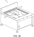
- FIG. 1 shows a perspective view of an electric grill 10 in accordance with one embodiment of the present invention. This is illustrated as a freestanding unit, but a grill incorporating the present invention could also be configured as a built-in unit.
- the grill 10 comprises a body 12 largely made of sheet metal. Grill bars 14 are provided above a heating chamber which is subscribed further below.
- the body 12 may include a vertical back plate 18.
- a hinged lid may also be provided which can close over the top of the grill bars 14 to provide an enclosed cooking chamber.
- the grill bars 14 are typically made of cast iron and are able to withstand temperatures up to about 250-350°C.
- FIGs 2a and 2b show part of the grill 10 in Figure 1 with the grill bars 14 removed to show the heating chamber 16 beneath.
- the heating chamber 16 is defined between a heating platform 20, side walls 22 and the grill bars 14 (when present).
- the heating platform 20 is electrically heated. Electrically powered heating elements may be located within the heating platform 20.
- the heating platform 20 may comprise two metal plates 20a,20b each with upper and lower surfaces.
- the lower surface of the upper plate 20a and the upper surface of the lower plate 20b are both machined with a number of grooves 24.
- the grooves 24 in each plate align to define channels into which heating elements are fitted.
- the grooves 24 may be semi-circular in cross-section so that when the plates 20a and 20b are sandwiched together, the grooves 24 align to define channels with a circular cross-section.
- Figure 2a shows the upper plate 20a in place and
- Figure 2b shows the lower plate 20b with the grooves 24, the upper plate 20a having been removed for illustrative purposes.
- the two plates 20a, 20b may both be formed of metal, e.g. steel, or another conductive material, for example a ceramic material such as silicon carbide. In this case, heat insulation may be provided underneath the heating platform 20.
- the lower plate 20b may itself be formed from an insulative material.
- the heating platform 20 is heated by the heating elements and acts as a primary heat source for cooking.
- the grill bars 14 which are located a short distance, e.g. 20-70 cm, above the heating platform 20 are heated largely by radiant heat and some convection from the heating platform 20.
- the grill bars 14 form a secondary heat source for cooking, but do not contain heating elements themselves.
- the heating platform 20 is typically heated to a temperature up to about 500°C, at which pyrolytic processes occur, and this enables the grill bars 14 to reach a temperature of 250-350°C.
- This source of primary heat provided by the heating elements set inside the heating platform 20 remains at a constant temperature, and so any required changes to the secondary heat source for different cooking styles can be achieved through adjustments to the depth between the grill bars 14 and the heating platform 20.
- Food items resting on the grill bars 14 are cooked through primarily by heat from the primary heat source, that is the heating platform 20. Direct contact of the food items with the secondary heat source, i.e. the grill bars 14, brands the food items with chargrill lines without completely burning the food items.
- the temperature which the grill bars 14 attain provides a suitable environment for the Maillard reaction to occur, which gives food its distinctive browned appearance and desirable flavour.
- the grill 10 of the present invention does not include a fat tray to collect excess fats and oils. Instead, the grill 10 further comprises a forced air supply system to help the oxidation process of any fat and oils produced by the foodstuffs that would otherwise drip down into the heating chamber 16 during cooking.
- the forced air supply results in cleaner burning of the fats and oils and a reduction of the black acrid smoke associated with partially burnt oils and fats.
- pyrolytic actions commence at around 500°C and with the addition of oxidation in an aerated environment provided by the forced air supply of the present invention, this can aid in the oxidation of the organic material into an inorganic dust or ash. Therefore, the grill 10 of the present invention ensures complete combustion of any oils and fats, leaving only light ash residue which can be easily vacuumed away during periodic cleaning. The grill 10 does not create fatty residues which present a risk of fire as well as health and environmental concerns.
- the heating chamber 16 is provided within a double-skinned support structure 26 which includes first and second air supplies which supply pressurised air into the heating chamber 16.
- the support structure 26 comprises inner and outer casings 28,30 nested together with an air chamber 32 between them. This can be seen in Figure 4 .
- the inner casing 28 has a centrally located opening 36. Below opening 36 there may be an air inlet assembly 34 comprising a perforated wall extending between the inner and outer casings 28,30 defining a central air chamber beneath the opening 36.
- the structure of the air inlet assembly 34 may be similar to that described in GB2511850 .
- a tube 46 extends upwardly from the opening 36 to the underside of the heating platform 20.
- the heating platform 20 is also provided with a central opening 38 which is coaxial, but of a smaller diameter, than the tube 46 and the opening 36.
- Pressurised air is supplied into the chamber 32, for example by fan 44 (which is shown only schematically in Figure 4 , although in practice this may be located within the body 12 of the grill 10, below the support structure 26).
- the first (primary) air supply delivers pressurised air into a central region of the heating chamber 16.
- Pressurised air from the air chamber 32 passes, via the air inlet assembly 34 and the opening 36 into the tube 46 and then through opening 38 in the heating platform 20 into the heating chamber 16.
- An air channelling device 40 is located in the opening 38 and protrudes up into the heating chamber 16 and down into the tube 46 towards opening 36.
- the air channelling device 40 comprises a central column with a plurality of radially projecting ribs. For example, there may be four projecting ribs, so that it is cruciform in cross-section as seen in Figures 3 and 5 .
- a circular cap 42 is located on the top end of the air channelling device 40 as seen in Figure 4 .
- the lower part of the air channelling device 40 can be seen in Figure 3 while the upper end, without the cap, is illustrated in Figure 6 .
- the air channelling device 40 divides the opening 38 in the heating platform 20 into four quadrants.
- the cap 42 deflects upward airflow passing through these four quadrants and diverts it laterally to flow out into the heating chamber 16 across the heating platform 20. This arrangement distributes airflow fairly evenly around the heating chamber 16.
- the secondary air supply comprises a plurality of openings 48 in the side walls 22 of the heating chamber 16.
- one or more openings 48 are provided in each side wall, located at one end near to a corner where one side wall 22 meets the next.
- the openings 48 communicate with the air chamber 32 formed in the support structure 26 and therefore jets of pressurised air exit the openings 48 into the heating chamber 16. Since the openings 48 are located towards the corners, this tends to create a vortex airflow which swirls around the heating chamber 16. This helps to pull the airflow from the primary air source in the centre outwardly, to ensure there is good airflow throughout the whole heating chamber 16. In addition, if any fat or oil droplets do combust, the airflow pushes such flare ups laterally rather than upwards. This minimises the flare up and also prevents the food being cooked from becoming burnt.
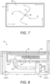
- Figure 7 is a schematic plan view of the heating platform 20 illustrating the airflow.
- the arrows P emanating out from the central opening 38 represent the airflow extending out in all directions from the first air supply.
- the arrows S extending from close to the corners and along the edges represent the airflow from the second air supply which tends to swirl around the heating chamber 16, in this case in an anticlockwise direction.
- the air flow from central opening 38 initially spreads out radially in all directions across the heating platform 22 but is gradually diverted by the air flow from openings 48 in order to create the vortex of air flowing around the opening 38.
- the forced airflow provided by the first and second air supplies permits fuller combustion of any fats and oils from the food items. Any flames which do occur burn more cleanly and quickly and the production of smoke is reduced or eliminated. Any residue will form ash or dust which can be cleared from the heating chamber 16 by vacuuming. No fatty residue or stagnant oil remains to be disposed of.
- the grill 10 of the present invention does not include a fat tray to collect fats and oils dripping from the food being cooked.
- the heating chamber 16 below the grill bars 14 is an enclosed, controlled environment with airflows provided in a controlled manner via the first and second air supplies. Air can only be exhausted from the heating chamber 16 from the top, through the grill bars 14. This contrasts with conventional grills which require fat trays beneath the grill bars and are therefore of a more open construction and subject to external, uncontrolled air movements below the grill bars.
- the enclosed heating chamber with controlled airflows provides the improved performance of the present invention.
- the grill cooks foodstuffs quickly and efficiently, to maintain flavour and texture and with minimal shrinkage. It also obtains the desired chargrill characteristics without burning the food or creating unwanted smoke and fatty residues.
- the entire heating chamber is heated to a very high temperature which allows the vapourisation of animal fats and oils to occur, minimising residues and keeping the food items succulent.
- FIG. 8 An alternative embodiment of the electric grill 10 of the present invention is shown in Figure 8 . This differs from the embodiment above in relation to certain features of the secondary air supply into the heating chamber 16, although the other features of the grill 10 are the same as described previously.
- the secondary airflow supplied to the openings 48 in the side walls 22 of the heating chamber 16 is drawn from a second air chamber 50 which is the space between the inner casing 28 and the underside of the heating platform 20.
- the air in this second air chamber 50 will be heated up when the grill 10 is in use and is drawn via a duct 52 connecting the space 50 to a fan 54.
- the fan 54 then supplies this heated air into the air chamber 32 between the inner and outer casings 28,30 of the support structure 26.
- This heated air then flows via the openings 48 into the heating chamber 16 to create the vortex airflow which swirls around the heating chamber 16.
- the heated air may also be supplied to the air inlet assembly 34 and into the centre of the heating platform 20 in the heating chamber 16.
- the primary air supply to the air inlet assembly 34 may be ambient air supplied by another fan.
- Providing heated air from the second air chamber 50 as the secondary airflow further improves the efficiency of the grill 10.
- Using air from the second air chamber 50 avoid excessive heat build-up in this part of the grill 10.
- supplying an already heated airflow into the heating chamber 16 maintains a higher temperature in the corners of the heating chamber 16. This in turn reduces the power requirements of the heating elements in the heating platform 20 so that lower wattage heating elements can be used to maintain an equivalent temperature in the heating chamber 16.
- the overall energy input required for the grill 10 is reduced, maximising the efficiency of the product.
Landscapes
- Engineering & Computer Science (AREA)
- Food Science & Technology (AREA)
- Baking, Grill, Roasting (AREA)
- Insulated Conductors (AREA)
- Non-Insulated Conductors (AREA)
Claims (14)
- Elektrischer Grill (10), der eine Heizplatte (20), eine Vielzahl von Seitenwänden (22), eine Vielzahl von Grillrost-Stäben (14), die im Abstand zueinander über der Heizplatte (20) angeordnet sind, sowie eine Heizkammer (16) umfasst, die zwischen der Heizplatte (20), den Seitenwänden (22) und den Grillrost-Stäben (14) festgelegt ist, wobei die Heizplatte (20) elektrisch aufgeheizt wird, dadurch gekennzeichnet, dass der Grill (10) weiter eine erste Luftzufuhr umfasst, die zentral in der Heizplatte (20) zur Bereitstellung von Druckluft in die Heizkammer (20) angeordnet ist und derart konfiguriert ist, dass sie einen Luftstrom gleichmäßig über die Heizplatte (20) lenkt, sowie eine zweite Luftzufuhr umfasst, die in den Seitenwänden (22) angeordnet ist und derart konfiguriert ist, dass sie einen Luftstrom entlang der Seitenwände (22) lenkt, um einen Luftwirbel zu erzeugen, der die zentral angeordnete Luftzufuhr umströmt.
- Elektrischer Grill (10) nach Anspruch 1, wobei die Heizplatte (20) zwei leitende Platten (20a, 20b) mit elektrischen Heizelementen umfasst, die zwischen den leitenden Platten eingebettet sind.
- Elektrischer Grill (10) nach Anspruch 2, wobei die erste Platte (20a) obere und untere Seiten umfasst und eine Vielzahl von Einkerbungen (24) auf der Unterseite ausgebildet sind, wobei die zweite Platte (20b) obere und untere Seiten umfasst und eine Vielzahl von Einkerbungen (24) in der Oberseite ausgebildet sind, wobei die Einkerbungen (24) in der ersten und zweiten Platte (20a, 20b) zusammenwirken, um Kanäle zur Aufnahme von Heizelementen zu bilden, wenn die erste und zweite Platte (20a, 20b) zusammengepresst werden.
- Elektrischer Grill (10) nach einem der vorhergehenden Ansprüche, wobei die Grillrost-Stäbe (14) keine Heizelemente enthalten und durch Bestrahlung von der Heizplatte (20) aufgeheizt werden.
- Elektrischer Grill (10) nach Anspruch 4, wobei die Heizplatte (20) konfiguriert ist, eine Temperatur von bis zu 500°C zu erreichen, so dass die Grillrost-Stäbe (14) auf eine Temperatur von bis zu 350°C aufgeheizt werden.
- Elektrischer Grill (10) nach einem der vorhergehenden Ansprüche, wobei die Heizplatte (20) aus Metall oder einem keramischen Werkstoff gebildet ist.
- Elektrischer Grill (10) nach einem der vorhergehenden Ansprüche, wobei die erste Luftzufuhr mindestens eine Öffnung (36) in der Heizplatte (20) umfasst, die mit einer Druckluftquelle und einem Luftstrom-Ablenkblech (40) verbunden ist, das zum Ablenken eines Luftstroms über der Oberfläche der Heizplatte (20) raus konfiguriert ist.
- Elektrischer Grill (10) nach Anspruch 7, wobei das Luftstrom-Ablenkblech (40) eine längliche Säule, die sich durch die Öffnung (36) in der Heizplatte (20) erstreckt, und eine Kappe (42) umfasst, die auf dem oberen Ende der Säule angebracht ist.
- Elektrischer Grill (10) nach Anspruch 8, wobei das Luftstrom-Ablenkblech (40) eine Säule mit einer Vielzahl von sich radial erstreckenden Lamellen umfasst.
- Elektrischer Grill (10) nach einem der vorhergehenden Ansprüche, wobei die zweite Luftzufuhr mindestens eine Öffnung (48) in jeder Seitenwand (22) umfasst, die neben einem Ende der Seitenwand (22) angeordnet ist und mit einer Druckluftquelle verbunden ist.
- Elektrischer Grill (20) nach einem der vorhergehenden Ansprüche, wobei die Heizplatte (20) und die Seitenwände (22) in einem Gehäuse (26) mit Innen- und Außenwänden (28, 30) und einer Luftkammer (32) zwischen der Innen- und Außenwand (28, 30) angeordnet sind, wobei die Luftkammer (32) mit einer Druckluftquelle verbunden ist und mit der Öffnung (36) in der Heizplatte (20) und mit den Öffnungen (48) in den Seitenwänden (22) in Verbindung steht.
- Elektrischer Grill (10) nach Anspruch 10 oder Anspruch 11, wobei die Druckluftquelle mindestens einen Lüfter (44) umfasst.
- Elektrischer Grill (10) nach Anspruch 10, wobei die Heizplatte (20) und die Seitenwände (22) in einem Gehäuse (26) mit Innen- und Außenwänden (28, 30) und einer ersten Luftkammer (32) zwischen der Innen- und Außenwand (28, 30) angeordnet sind, wobei die Luftkammer (32) mit einer Druckluftquelle verbunden ist und mit den Öffnungen (48) in den Seitenwänden (28, 30) der Heizkammer (16) in Verbindung steht, und wobei das Gehäuse weiter eine zweite Luftkammer (50) umfasst, die zwischen der Heizplatte (20) und der Innenwand (28) des Gehäuses (26) festgelegt ist, wobei die Druckluftquelle einen Lüfter (54) umfasst, der konfiguriert ist, Luft aus der zweiten Luftkammer (50) zu saugen und diese der ersten Luftkammer (32) zuzuführen.
- Elektrischer Grill (10) nach einem der vorhergehenden Ansprüche, der weiter einen Deckel umfasst, der über den Grillrost-Stäben (14) schließbar ist, um einen abgeschlossenen Garraum bereitzustellen.
Priority Applications (2)
| Application Number | Priority Date | Filing Date | Title |
|---|---|---|---|
| HRP20250242TT HRP20250242T1 (hr) | 2020-10-29 | 2021-10-27 | Električni roštilj |
| RS20250189A RS66540B1 (sr) | 2020-10-29 | 2021-10-27 | Električni roštilj |
Applications Claiming Priority (3)
| Application Number | Priority Date | Filing Date | Title |
|---|---|---|---|
| GB2017147.6A GB2600443B (en) | 2020-10-29 | 2020-10-29 | Electric grill |
| GBGB2103717.1A GB202103717D0 (en) | 2020-10-29 | 2021-03-17 | Electric grill |
| PCT/EP2021/079836 WO2022090317A1 (en) | 2020-10-29 | 2021-10-27 | Electric grill |
Publications (3)
| Publication Number | Publication Date |
|---|---|
| EP4236741A1 EP4236741A1 (de) | 2023-09-06 |
| EP4236741C0 EP4236741C0 (de) | 2024-11-27 |
| EP4236741B1 true EP4236741B1 (de) | 2024-11-27 |
Family
ID=73776380
Family Applications (1)
| Application Number | Title | Priority Date | Filing Date |
|---|---|---|---|
| EP21801514.7A Active EP4236741B1 (de) | 2020-10-29 | 2021-10-27 | Elektrischer grill |
Country Status (15)
| Country | Link |
|---|---|
| US (1) | US20240023756A1 (de) |
| EP (1) | EP4236741B1 (de) |
| JP (1) | JP7575596B2 (de) |
| CN (1) | CN116507251B (de) |
| AU (1) | AU2021372731A1 (de) |
| CA (1) | CA3198883A1 (de) |
| ES (1) | ES3014077T3 (de) |
| GB (2) | GB2600443B (de) |
| HR (1) | HRP20250242T1 (de) |
| HU (1) | HUE070629T2 (de) |
| IL (1) | IL302463B1 (de) |
| PL (1) | PL4236741T3 (de) |
| RS (1) | RS66540B1 (de) |
| WO (1) | WO2022090317A1 (de) |
| ZA (1) | ZA202305637B (de) |
Family Cites Families (15)
| Publication number | Priority date | Publication date | Assignee | Title |
|---|---|---|---|---|
| DE3104265A1 (de) * | 1980-08-13 | 1982-04-15 | Micropore International Ltd | Elektroherd mit warn- und restwaermeanzeige der kochflaechen |
| WO1988000681A1 (en) * | 1985-07-10 | 1988-01-28 | Archer Aire Industries, Inc. | Air slot cooking grill |
| CA1300448C (en) * | 1987-08-04 | 1992-05-12 | Jean-Pierre Patenaude | Barbecue device |
| KR20050002677A (ko) * | 2004-08-12 | 2005-01-10 | (주)윤창 | 전기구이기의 공기순환구조 |
| KR100743347B1 (ko) * | 2005-07-12 | 2007-07-26 | 강규석 | 로스터의 공기 순환시스템 |
| JP2007289649A (ja) | 2006-04-20 | 2007-11-08 | Kyu Suk Kang | ロースターの空気循環システムおよびロースター |
| JP4392724B2 (ja) | 2007-11-02 | 2010-01-06 | 日本電熱株式会社 | サセプタ |
| US20100089248A1 (en) * | 2008-10-10 | 2010-04-15 | Edward Michael Jones | Convection grill |
| GB2511850B (en) | 2013-03-15 | 2016-04-20 | Active Food Systems Ltd | Cooking Apparatus |
| KR101803836B1 (ko) | 2017-03-09 | 2017-12-04 | 최승혁 | 유증기 및 연기 정화 순환시스템을 구비한 전기구이기 |
| KR102515514B1 (ko) * | 2017-07-20 | 2023-03-29 | 코웨이 주식회사 | 흡입 유로를 구비한 전열식 조리기구 |
| GB2567836B (en) * | 2017-10-25 | 2019-12-04 | Active Food Systems Ltd | Cooking apparatus |
| CN108720645A (zh) * | 2018-06-05 | 2018-11-02 | 佛山市顺德区唯点工业设计有限公司 | 一种基于烟气余热二次利用的节能环保型烧烤炉 |
| CN209482113U (zh) * | 2018-12-28 | 2019-10-11 | 长安大学 | 一种可快速加固的简支工字型组合梁 |
| CN109528028A (zh) * | 2019-01-17 | 2019-03-29 | 宁波吉盛电器有限公司 | 一种红外均温装置及其烧烤炉 |
-
2020
- 2020-10-29 GB GB2017147.6A patent/GB2600443B/en active Active
-
2021
- 2021-03-17 GB GBGB2103717.1A patent/GB202103717D0/en not_active Ceased
- 2021-10-27 CA CA3198883A patent/CA3198883A1/en active Pending
- 2021-10-27 ES ES21801514T patent/ES3014077T3/es active Active
- 2021-10-27 RS RS20250189A patent/RS66540B1/sr unknown
- 2021-10-27 IL IL302463A patent/IL302463B1/en unknown
- 2021-10-27 EP EP21801514.7A patent/EP4236741B1/de active Active
- 2021-10-27 JP JP2023526221A patent/JP7575596B2/ja active Active
- 2021-10-27 PL PL21801514.7T patent/PL4236741T3/pl unknown
- 2021-10-27 HR HRP20250242TT patent/HRP20250242T1/hr unknown
- 2021-10-27 US US18/033,015 patent/US20240023756A1/en active Pending
- 2021-10-27 WO PCT/EP2021/079836 patent/WO2022090317A1/en not_active Ceased
- 2021-10-27 AU AU2021372731A patent/AU2021372731A1/en active Pending
- 2021-10-27 CN CN202180073796.1A patent/CN116507251B/zh active Active
- 2021-10-27 HU HUE21801514A patent/HUE070629T2/hu unknown
-
2023
- 2023-05-25 ZA ZA2023/05637A patent/ZA202305637B/en unknown
Also Published As
| Publication number | Publication date |
|---|---|
| CN116507251B (zh) | 2025-12-16 |
| IL302463A (en) | 2023-06-01 |
| WO2022090317A1 (en) | 2022-05-05 |
| ZA202305637B (en) | 2024-10-30 |
| ES3014077T3 (en) | 2025-04-16 |
| GB202103717D0 (en) | 2021-04-28 |
| EP4236741C0 (de) | 2024-11-27 |
| AU2021372731A9 (en) | 2024-08-08 |
| AU2021372731A1 (en) | 2023-06-22 |
| EP4236741A1 (de) | 2023-09-06 |
| CA3198883A1 (en) | 2022-05-05 |
| JP7575596B2 (ja) | 2024-10-29 |
| GB2600443B (en) | 2023-03-01 |
| PL4236741T3 (pl) | 2025-04-07 |
| GB2600443A (en) | 2022-05-04 |
| JP2023547467A (ja) | 2023-11-10 |
| HRP20250242T1 (hr) | 2025-04-11 |
| GB202017147D0 (en) | 2020-12-16 |
| RS66540B1 (sr) | 2025-03-31 |
| CN116507251A (zh) | 2023-07-28 |
| HUE070629T2 (hu) | 2025-06-28 |
| IL302463B1 (en) | 2025-12-01 |
| US20240023756A1 (en) | 2024-01-25 |
Similar Documents
| Publication | Publication Date | Title |
|---|---|---|
| US5755154A (en) | Gas barbecue assembly | |
| CN101479533B (zh) | 燃烧改进的固体燃料炉 | |
| EP2133014B1 (de) | Kochgefäß zur Verwendung mit Gasherden | |
| EP1521543B1 (de) | Holzbefeuertes barbecuegerät | |
| EP3244780B1 (de) | System und verfahren zur verbesserung der holzkohleverbrennung zum kochen | |
| JP4453907B2 (ja) | ガスコンロ | |
| EP4236741B1 (de) | Elektrischer grill | |
| EP3845099B1 (de) | Gas-luft-fritteuse | |
| KR100796321B1 (ko) | 구이 장치 | |
| JP2007301327A (ja) | 焼き物調理器 | |
| KR101694156B1 (ko) | 다기능 구이기 | |
| CN222075036U (zh) | 一种多功能烧烤架 | |
| JP2000232945A (ja) | 両面焼グリル | |
| KR102415462B1 (ko) | 다목적 화덕 | |
| JP2018185138A (ja) | 炭、練炭、豆炭等の固形燃料用の火起こし装置および火起こし装置を内蔵した卓上調理具 | |
| JP2000217718A (ja) | 両面焼グリル | |
| JPH075785Y2 (ja) | 肉等焼物用の焜炉 | |
| KR200293025Y1 (ko) | 2중 구조를 가지는 고기 구이용 판 | |
| KR970005247Y1 (ko) | 일회용 숯불화로 | |
| JP3111522U (ja) | 焼物装置における側壁冷却機構 | |
| KR200162793Y1 (ko) | 자연대류방식의 케이싱 냉각구조를 갖는 전기 조리용기 | |
| KR20150004114U (ko) | 다용도 불판 및 이를 이용한 불판 장치 | |
| JP2021134972A (ja) | ストーブ | |
| CA2491092A1 (en) | Wood fed barbecue apparatus | |
| JPH0875167A (ja) | グリル付ガスコンロ |
Legal Events
| Date | Code | Title | Description |
|---|---|---|---|
| REG | Reference to a national code |
Ref country code: HR Ref legal event code: TUEP Ref document number: P20250242T Country of ref document: HR |
|
| STAA | Information on the status of an ep patent application or granted ep patent |
Free format text: STATUS: UNKNOWN |
|
| STAA | Information on the status of an ep patent application or granted ep patent |
Free format text: STATUS: THE INTERNATIONAL PUBLICATION HAS BEEN MADE |
|
| PUAI | Public reference made under article 153(3) epc to a published international application that has entered the european phase |
Free format text: ORIGINAL CODE: 0009012 |
|
| STAA | Information on the status of an ep patent application or granted ep patent |
Free format text: STATUS: REQUEST FOR EXAMINATION WAS MADE |
|
| 17P | Request for examination filed |
Effective date: 20230517 |
|
| AK | Designated contracting states |
Kind code of ref document: A1 Designated state(s): AL AT BE BG CH CY CZ DE DK EE ES FI FR GB GR HR HU IE IS IT LI LT LU LV MC MK MT NL NO PL PT RO RS SE SI SK SM TR |
|
| DAV | Request for validation of the european patent (deleted) | ||
| DAX | Request for extension of the european patent (deleted) | ||
| GRAP | Despatch of communication of intention to grant a patent |
Free format text: ORIGINAL CODE: EPIDOSNIGR1 |
|
| STAA | Information on the status of an ep patent application or granted ep patent |
Free format text: STATUS: GRANT OF PATENT IS INTENDED |
|
| INTG | Intention to grant announced |
Effective date: 20240528 |
|
| RIN1 | Information on inventor provided before grant (corrected) |
Inventor name: O'ROURKE, SAM Inventor name: EDWARDS, ANDREW NORMAN Inventor name: CADBURY, GEORGE JUSTIN PETER |
|
| GRAS | Grant fee paid |
Free format text: ORIGINAL CODE: EPIDOSNIGR3 |
|
| GRAA | (expected) grant |
Free format text: ORIGINAL CODE: 0009210 |
|
| STAA | Information on the status of an ep patent application or granted ep patent |
Free format text: STATUS: THE PATENT HAS BEEN GRANTED |
|
| AK | Designated contracting states |
Kind code of ref document: B1 Designated state(s): AL AT BE BG CH CY CZ DE DK EE ES FI FR GB GR HR HU IE IS IT LI LT LU LV MC MK MT NL NO PL PT RO RS SE SI SK SM TR |
|
| REG | Reference to a national code |
Ref country code: GB Ref legal event code: FG4D |
|
| REG | Reference to a national code |
Ref country code: CH Ref legal event code: EP |
|
| REG | Reference to a national code |
Ref country code: DE Ref legal event code: R096 Ref document number: 602021022537 Country of ref document: DE |
|
| REG | Reference to a national code |
Ref country code: IE Ref legal event code: FG4D |
|
| U01 | Request for unitary effect filed |
Effective date: 20241216 |
|
| U07 | Unitary effect registered |
Designated state(s): AT BE BG DE DK EE FI FR IT LT LU LV MT NL PT RO SE SI Effective date: 20250110 |
|
| PG25 | Lapsed in a contracting state [announced via postgrant information from national office to epo] |
Ref country code: IS Free format text: LAPSE BECAUSE OF FAILURE TO SUBMIT A TRANSLATION OF THE DESCRIPTION OR TO PAY THE FEE WITHIN THE PRESCRIBED TIME-LIMIT Effective date: 20250327 |
|
| REG | Reference to a national code |
Ref country code: HR Ref legal event code: T1PR Ref document number: P20250242 Country of ref document: HR |
|
| REG | Reference to a national code |
Ref country code: ES Ref legal event code: FG2A Ref document number: 3014077 Country of ref document: ES Kind code of ref document: T3 Effective date: 20250416 |
|
| REG | Reference to a national code |
Ref country code: SK Ref legal event code: T3 Ref document number: E 46008 Country of ref document: SK |
|
| REG | Reference to a national code |
Ref country code: GR Ref legal event code: EP Ref document number: 20250400438 Country of ref document: GR Effective date: 20250409 |
|
| REG | Reference to a national code |
Ref country code: HU Ref legal event code: AG4A Ref document number: E070629 Country of ref document: HU |
|
| PG25 | Lapsed in a contracting state [announced via postgrant information from national office to epo] |
Ref country code: SM Free format text: LAPSE BECAUSE OF FAILURE TO SUBMIT A TRANSLATION OF THE DESCRIPTION OR TO PAY THE FEE WITHIN THE PRESCRIBED TIME-LIMIT Effective date: 20241127 |
|
| PLBE | No opposition filed within time limit |
Free format text: ORIGINAL CODE: 0009261 |
|
| STAA | Information on the status of an ep patent application or granted ep patent |
Free format text: STATUS: NO OPPOSITION FILED WITHIN TIME LIMIT |
|
| REG | Reference to a national code |
Ref country code: CH Ref legal event code: L10 Free format text: ST27 STATUS EVENT CODE: U-0-0-L10-L00 (AS PROVIDED BY THE NATIONAL OFFICE) Effective date: 20251008 |
|
| PGFP | Annual fee paid to national office [announced via postgrant information from national office to epo] |
Ref country code: PL Payment date: 20250930 Year of fee payment: 5 |
|
| REG | Reference to a national code |
Ref country code: CH Ref legal event code: U11 Free format text: ST27 STATUS EVENT CODE: U-0-0-U10-U11 (AS PROVIDED BY THE NATIONAL OFFICE) Effective date: 20251101 |
|
| 26N | No opposition filed |
Effective date: 20250828 |
|
| REG | Reference to a national code |
Ref country code: HR Ref legal event code: ODRP Ref document number: P20250242 Country of ref document: HR Payment date: 20250930 Year of fee payment: 5 |
|
| PGFP | Annual fee paid to national office [announced via postgrant information from national office to epo] |
Ref country code: HU Payment date: 20251008 Year of fee payment: 5 |
|
| U20 | Renewal fee for the european patent with unitary effect paid |
Year of fee payment: 5 Effective date: 20251020 |
|
| PGFP | Annual fee paid to national office [announced via postgrant information from national office to epo] |
Ref country code: GB Payment date: 20251020 Year of fee payment: 5 |
|
| PGFP | Annual fee paid to national office [announced via postgrant information from national office to epo] |
Ref country code: NO Payment date: 20251023 Year of fee payment: 5 |
|
| PGFP | Annual fee paid to national office [announced via postgrant information from national office to epo] |
Ref country code: HR Payment date: 20251001 Year of fee payment: 5 |
|
| PGFP | Annual fee paid to national office [announced via postgrant information from national office to epo] |
Ref country code: TR Payment date: 20251008 Year of fee payment: 5 Ref country code: GR Payment date: 20251020 Year of fee payment: 5 |
|
| PGFP | Annual fee paid to national office [announced via postgrant information from national office to epo] |
Ref country code: CH Payment date: 20251101 Year of fee payment: 5 |
|
| PGFP | Annual fee paid to national office [announced via postgrant information from national office to epo] |
Ref country code: CZ Payment date: 20250930 Year of fee payment: 5 Ref country code: IE Payment date: 20251017 Year of fee payment: 5 Ref country code: CY Payment date: 20251014 Year of fee payment: 5 |
|
| PGFP | Annual fee paid to national office [announced via postgrant information from national office to epo] |
Ref country code: SK Payment date: 20251008 Year of fee payment: 5 |
|
| PGFP | Annual fee paid to national office [announced via postgrant information from national office to epo] |
Ref country code: RS Payment date: 20251002 Year of fee payment: 5 |
|
| PGFP | Annual fee paid to national office [announced via postgrant information from national office to epo] |
Ref country code: ES Payment date: 20251114 Year of fee payment: 5 |