EP4234841B1 - Einweg-einziehbare gebäudeschalungsvorrichtung - Google Patents
Einweg-einziehbare gebäudeschalungsvorrichtung Download PDFInfo
- Publication number
- EP4234841B1 EP4234841B1 EP23151152.8A EP23151152A EP4234841B1 EP 4234841 B1 EP4234841 B1 EP 4234841B1 EP 23151152 A EP23151152 A EP 23151152A EP 4234841 B1 EP4234841 B1 EP 4234841B1
- Authority
- EP
- European Patent Office
- Prior art keywords
- bar
- along
- fixed plate
- extending direction
- side bar
- Prior art date
- Legal status (The legal status is an assumption and is not a legal conclusion. Google has not performed a legal analysis and makes no representation as to the accuracy of the status listed.)
- Active
Links
Images


Classifications
-
- E—FIXED CONSTRUCTIONS
- E04—BUILDING
- E04G—SCAFFOLDING; FORMS; SHUTTERING; BUILDING IMPLEMENTS OR AIDS, OR THEIR USE; HANDLING BUILDING MATERIALS ON THE SITE; REPAIRING, BREAKING-UP OR OTHER WORK ON EXISTING BUILDINGS
- E04G11/00—Forms, shutterings, or falsework for making walls, floors, ceilings, or roofs
- E04G11/06—Forms, shutterings, or falsework for making walls, floors, ceilings, or roofs for walls, e.g. curved end panels for wall shutterings; filler elements for wall shutterings; shutterings for vertical ducts
- E04G11/20—Movable forms; Movable forms for moulding cylindrical, conical or hyperbolical structures; Templates serving as forms for positioning blocks or the like
-
- E—FIXED CONSTRUCTIONS
- E04—BUILDING
- E04G—SCAFFOLDING; FORMS; SHUTTERING; BUILDING IMPLEMENTS OR AIDS, OR THEIR USE; HANDLING BUILDING MATERIALS ON THE SITE; REPAIRING, BREAKING-UP OR OTHER WORK ON EXISTING BUILDINGS
- E04G9/00—Forming or shuttering elements for general use
- E04G9/08—Forming boards or similar elements, which are collapsible, foldable, or able to be rolled up
-
- E—FIXED CONSTRUCTIONS
- E04—BUILDING
- E04G—SCAFFOLDING; FORMS; SHUTTERING; BUILDING IMPLEMENTS OR AIDS, OR THEIR USE; HANDLING BUILDING MATERIALS ON THE SITE; REPAIRING, BREAKING-UP OR OTHER WORK ON EXISTING BUILDINGS
- E04G11/00—Forms, shutterings, or falsework for making walls, floors, ceilings, or roofs
- E04G11/06—Forms, shutterings, or falsework for making walls, floors, ceilings, or roofs for walls, e.g. curved end panels for wall shutterings; filler elements for wall shutterings; shutterings for vertical ducts
- E04G11/08—Forms, which are completely dismantled after setting of the concrete and re-built for next pouring
- E04G11/082—Retractable forms for the inside face of at least three walls
Definitions
- the invention relates to a one-way retractable building formwork apparatus.
- An existing building formwork apparatus includes at least four formworks and at least one connecting hornbeam block.
- Each formwork has a mold surface at one side thereof, a mounting surface opposite to the mold surface, and two connecting posts disposed on upper and lower ends of the mounting surface.
- Each connecting post has a plurality of through holes.
- the connecting hornbeam block has a plurality of connecting holes.
- the connecting hornbeam block is then disposed on the connecting posts of the formworks, after which a plurality of fasteners are extended through the through holes and the connecting holes to fix the formworks and the connecting hornbeam block, thereby forming the existing building formwork apparatus.
- Grout is poured between two existing building formwork apparatuses to make a wall. Since the dimensions of the wall differ due to different engineering works, and since there is no way to have a standard building formwork apparatus available, assembly of the existing building formwork apparatuses may not conform to the desired dimensions of the wall to be made, so that it is necessary to customize the existing building formwork apparatus so as to conform to the desired dimensions of the wall to be constructed.
- an object of the present invention is to provide a one way retractable building formwork apparatus that can alleviate at least one of the drawbacks of the prior art.
- the one-way retractable building formwork apparatus for mounting on a mounting surface of a substrate module includes a first side bar configured to be disposed on one end of the mounting surface that extends along a lateral direction, a second side bar configured to be disposed on another end of the mounting surface that extends along the lateral direction and opposite to the first side bar along an extending direction transverse to the lateral direction, and a retractable unit configured to be disposed on the mounting surface and connected to the first side bar.
- the retractable unit is extendable along the extending direction to fixedly connect to the second side bar.
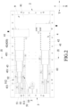
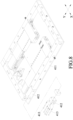
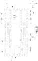
- a one-way retractable building formwork apparatus is configured to be mounted on a mounting surface 91 of a substrate module 9, and includes a first side bar 2, a second side bar 3, a retractable unit 4 and a side connection unit 5.
- the first side bar 2 is disposed on one end of the mounting surface 91 that extends along a lateral direction (X).
- the second side bar 3 is disposed on another end of the mounting surface 91 that extends along the lateral direction (X), and is opposite to the first side bar 2 along an extending direction (Y) transverse to the lateral direction (X).
- the retractable unit 4 is disposed on the mounting surface 91, is connected to the first side bar 2, and is extendable along the extending direction (Y) to fixedly connect to the second side bar 3.
- the retractable unit 4 includes two side bar modules 41, two fixed plate assemblies 42, and two side plate assemblies 43.
- the side bar modules 41 extend along the extending direction (Y), and are disposed on another two opposite ends of the mounting surface 91 that extend along the extending direction (Y) such that the side bar modules 41 are opposite to each other along the lateral direction (X).
- the side bar modules 41 are fixedly connected to two opposite ends of the first side bar 2.
- the fixed plate assemblies 42 are disposed on the mounting surface 91 between the first and second side bars 2, 3.
- the side plate assemblies 43 are respectively inserted into the fixed plate assemblies 42, and are extendable out of the same along the extending direction (Y) to fixedly connect to the second side bar 3.
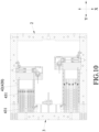
- the fixed plate assembly 42 includes a guide fixed plate 420 having a pair of inner rails 4201.
- the side plate assembly 43 includes a plurality of side plates 431 telescopically connected to one another. An outermost one of the side plates 431 is slidably inserted into the guide fixed plate 420; and, an innermost one of the side plates 431 is slidably engaged with and is extendable out of an adjacent one of the side plates 431 to fixedly connect to the second side bar 3.
- Each side plate 431 has a pair of inner rails 4311 extending along a length thereof, and a pair of outer rails 4312 opposite to the pair of inner rails 4311 and extending also along the length thereof.
- each inner rail 4311 is in the form of a groove having a T-shaped cross section
- each outer rail 4312 is in the form of a protrusion having a T-shaped cross section, but not limited thereto.
- the pair of the outer rails 4312 of the outermost side plate 431 are slidably engaged with the pair of the inner rails 4201 of the guide fixed plate 420 to limit the outermost side plate 431 to adjust the position thereof only along the extending direction (Y).
- the pair of the outer rails 4312 of one of each two adjacent ones of the side plates 431 are slidably engaged with the pair of the inner rails 4312 of the other side plate 431 to limit the one of each two adjacent side plates 431 to adjust the position thereof only along the extending direction (Y).
- Each outer rail 4312 of each side plate 431 is provided with a plurality of threaded holes 4313 spacedly arranged along the length thereof.
- the side connection unit 5 includes a plurality of side connectors 51 and a plurality of fixing screws 52.
- Each side connector 51 includes a base plate 511 disposed on the mounting surface 91, and a vertical plate 512 extending upwardly from one end of the base plate 511 and adjacent to a respective one of the side plates 431.
- Some of the fixing screws 52 are respectively inserted through elongated holes in the base plates 511 of the side connectors 51 to fix the base plates 511 to the mounting surface 91.
- Each of the other ones of the fixing screws 52 is inserted through an elongated hole in a respective one of the vertical plates 512 of the side connectors 51 and is threadedly connected to a selected one of the threaded holes 4313 in a respective one of the side plates 431 to fix each vertical plate 512 to the respective side plate 431 along the lateral direction (X).
- a plurality of basic building formworks (not shown) having fixed dimensions are first made according to a wall to be constructed, and then, according to the length difference between an assembly of the basic building formworks and the wall to be constructed, the substrate module 9 that meets the length difference is further manufactured.
- the first side bar 2, the second side bar 3 and the side bar modules 41 corresponding to the dimensions of the substrate module 9 are fixedly connected to the mounting surface 91 of the substrate module 9 through a plurality of screws, and the first side bar 2 is fixed between the side bar modules 41 through a plurality of screws.
- the fixed plate assembly 42 is also fixed to the mounting surface 91 through a plurality of screws, and the side plates 431 inside the guide fixed plate 420 of the fixed plate assembly 42 are pulled out toward the second side bar 3 along the extending direction (Y) to fix the innermost side plate 431 to the second side bar 3 through a plurality of screws.
- the side plates 431 are fixed to their respective positions through the side connectors 51 and the fixing screws 52, thereby achieving the effect of strengthening the substrate module 9. Since the side plates 431 are retractable relative to the guide fixed plate 420, they are suitable for use in different dimensions of the substrate module 9.
- the one-way retractable building formwork apparatus After the components of the one-way retractable building formwork apparatus are assembled to the substrate module 9, the one-way retractable building formwork apparatus together with the substrate module 9 is then assembled to the basic building formworks so as to meet the dimensions of the wall to be constructed, thereby saving the labor cost.
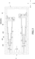
- a one-way retractable building formwork apparatus is shown to be identical to the first embodiment, but differs in that, in the second embodiment, the substrate module 9 includes a first substrate 92 and a second substrate 93 adjacently connected to each other along the extending direction (Y).
- the first substrate 92 has a first surface 921
- the second substrate 93 has a second surface 931 in the same direction as the first surface 921.
- the first side bar 2 is disposed on one end of the first surface 921 that extends along the lateral direction (X) and that is distal to the second surface 931.
- the second side bar 3 is disposed on one end of the second surface 931 that extends along the lateral direction (X) and that is opposite to the first side bar 2 along the extending direction (Y).
- the retractable unit 4 is disposed on the first surface 921, and is retractably connected to the second side bar 3.
- the first substrate 92 is made of a material having fixed dimensions
- the second substrate 93 is made of a leftover material from the previous projects, but not limited thereto. That is, the first and second substrates 92, 93 may both be made of the leftover materials.
- each side bar module 41 includes a main side bar 411 extending the extending direction (Y) and fixedly connected to one end of the first side bar 2, three extension side bars 412 sequentially arranged along the extending direction (Y), and five side bar screws 413 inserted through the extension side bars 412 along the extending direction (Y) and screwed to the main side bar 411 to thereby connect the extension side bars 412 to the main side bar 411.
- the longest one of the extension side bars 412 is disposed immediately adjacent to the main side bar 411 at a side opposite to the first side bar 2.
- the main side bar 411 is made of a material having fixed dimensions, while the extension side bars 412 are made of leftover materials from the previous projects, but not limited thereto.
- the main side bar 411 and the extension side bars 412 may all be made of the leftover materials.
- the extension side bars 412 may be directly fixed to the second surface 931 using the side bar screws 413, and the side bar screws 413 may not be limited to extend through the extension side bars 412 along the extending direction (Y), but may extend through the extension side bars 412 in a direction transverse to the extending direction (Y) and the lateral direction (X) to similarly achieve the fixing effect.
- the second embodiment can achieve the same effect as that of the first embodiment. Further, since the substrate module 9 can be formed by splicing multiple substrates and the side bar modules 41 can also be formed by splicing multiple extension side bars, different lengths of the substrate module 9 and the side bar modules 41 can thus be made.
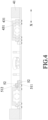
- a one-way retractable building formwork apparatus is shown to be identical to the second embodiment, but differs in that only the outermost side plate 431 is partially extended out of the guide fixed plate 420 of the fixed plate assembly 42 of the retractable unit 4.
- the third embodiment can achieve the same effect as that of the second embodiment, and is suitable for use with the substrate module 9 having a short length along the extending direction (Y).
- a one-way retractable building formwork apparatus is shown to be identical to the first embodiment, but differs in that, in the fourth embodiment, the substrate module 9 includes a first substrate 92 and a second substrate 93 adjacently connected to each other along the extending direction (Y).
- the first substrate 92 has a first surface 921
- the second substrate 93 has a second surface 931 in the same direction as the first surface 921.
- the first side bar 2 is disposed on one end of the first surface 921 that extends along the lateral direction (X) and that is distal to the second surface 931.
- the second side bar 3 is disposed on one end of the second surface 931 that extends along the lateral direction (X) and that is opposite to the first side bar 2 along the extending direction (Y).
- the retractable unit 4 is disposed on the first surface 921, and is retractably connected to the second side bar 3.
- the retractable unit 4 includes the two side bar modules 41, but only one fixed plate assembly 42 and only one side plate assembly 43.
- the fourth embodiment can achieve the same effect as that of the first embodiment, and is suitable for use with the substrate module 9 having a short length along the lateral direction (X).
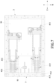
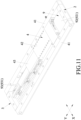
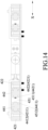
- a one-way retractable building formwork apparatus according to the fifth embodiment according to the invention is shown to be identical to the first embodiment, but differs in that, in the fifth embodiment, the retractable unit 4' includes two fixed plate assemblies 42', two connecting bar assemblies 44, and two slide bar assemblies 45.
- the side bar modules 41 are omitted in this embodiment.
- only one of each of the fixed plate assemblies 42', the connecting bar assemblies 44 and the slide bar assemblies 45 will be described below.
- the fixed plate assembly 42 includes a first fixed plate 421 that extends along the extending direction (Y), that is disposed on one end of the mounting surface 91 which extends along the extending direction (Y) and that is fixed to one end of the first side bar 2, and a second fixed plate 422 that extends along the extending direction (Y), that is spaced apart from and that is located inwardly of the first fixed plate 421 along the lateral direction (X) and that is shorter than the first fixed plate 421.
- Each of the first and second side plates 421, 422 has a slide groove 4211, 4221 extending along a length thereof and having a T-shaped cross section. The slide grooves 4211, 4221 of the first and second side plates 421, 422 face each other.
- the connecting bar assembly 44 includes a first connecting bar 441 and a second connecting bar 442 extending along the extending direction (Y) and located between the first and second fixed plates 421, 422.
- Each of the first and second connecting bars 441, 442 has an inner rail 4411, 4421 and an outer rail 4412, 4422 respectively provided on two opposite sides thereof that are opposite along the lateral direction (X) and extending along a length thereof.
- Each of the inner and outer rails 4411, 4421, 4412, 4422 has a T-shaped cross section.
- the outer rail 4412 of the first connecting bar 441 is slidably inserted into the slide groove 4211 of the first fixed plate 421.
- the outer rail 4422 of the second connecting bar 442 is slidably inserted into the slide groove 4221 of the second fixed plate 422.
- the slide bar assembly 45 of this embodiment includes one slide bar 451 extending along the extending direction (Y) and having an inner groove 4511 and an outer groove 4512 respectively provided on two opposite sides thereof that are opposite along the lateral direction (X) and extending along a length thereof.
- Each of the inner and outer grooves 4511, 4512 has a T-shaped cross section.
- the inner groove 4511 is slidably engaged with the inner rail 4421 of the second connecting bar 442, while the outer groove 4512 is slidably engaged with the inner rail 4411 of the first connecting bar 441.
- the slide bar 451 is slidable between the first and second connecting bars 441, 442 along the extending direction (Y) to fixedly connect to the second side bar 3.
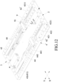
- the connecting bar assemblies 44 are sequentially connected in series from outside to inside.
- the first and second connecting bars 441, 442 of an outermost one of the connecting bar assemblies 44 are slidably engaged to the respective first and second side plates 421, 422 of the fixed plate assembly 42'.
- the first and second connecting bars 441, 442 of an inner one of the connecting bar assemblies 44 are slidably engaged to the respective first and second connecting bars 441, 442 of an adjacent outer one of the connecting bar assemblies 44.
- the slide bar 451 is slidably engaged between the first and second connecting bars 441, 442 of an innermost one of the connecting bar assemblies 44.
- a slidable connection between the fixed plate assembly 42 and the outermost connecting bar assembly 44, between two adjacent connecting bar assemblies 44, and between the slide bar 451 and the innermost connecting bar assembly 44 are by way of slide groove and slide rail engagement to limit the first and second connecting bars 441, 442 of the connecting bar assemblies 44 and the slide bar 451 to adjust the position thereof only along the extending direction (Y).
- the connecting bar assemblies 44 may be omitted, so that the slide bar 451 can be slidably inserted between the first and second side plates 421, 422 of the fixed plate assembly 42.
- a slidable connection between the slide bar 451 and the first and second side plates 421, 422 is by way of slide groove and slide rail engagement to limit the slide bar 451 to adjust the position thereof only along the extending direction (Y).
- the fifth embodiment can achieve the same effect as that of the first embodiment. Further, since the slide bars 451 of the slide bar assemblies 45 are retractable relative to the respective connecting bar assemblies 44 or the respective fixed plate assemblies 42, this embodiment is suitable for use with the substrate module 9 having different dimensions.
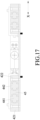
- a one-way retractable building formwork apparatus is shown to be identical to the fifth embodiment, but differs in that, in the sixth embodiment, the substrate module 9 includes a first substrate 92 and a second substrate 93 adjacently connected to each other along the extending direction (Y).
- the first substrate 92 has a first surface 921
- the second substrate 93 has a second surface 931 in the same direction as the first surface 921.
- the first side bar 2 is disposed on one end of the first surface 921 that extends along the lateral direction (X) and that is distal to the second surface 931.
- the second side bar 3 is disposed on one end of the second surface 931 that extends along the lateral direction (X) and that is opposite to the first side bar 2 along the extending direction (Y).
- the retractable unit 4' is disposed on the first surface 921, and is retractably connected to the second side bar 3.
- the connecting bar assemblies 44 and the slide bar assemblies 45 of the retractable unit 4' are not extended, and the first fixed plate 421 of each fixed plate assembly 42 includes a plurality of interconnected side plate portions 4211 extending along the extending direction (Y).
- the sixth embodiment can achieve the same effect as that of the fifth embodiment. Since the substrate module 9 can be formed by splicing multiple substrates and the first fixed plate 421 can also be formed by splicing multiple side plate portions, different lengths of the substrate module 9 and the first fixed plate 421 can thus be made.
- the structure of the substrate module 9 can be strengthened. Further, since the substrate module 9 can be formed by splicing multiple substrates which can be made of leftover materials from the previous projects, and since the side bar modules 41 can also be formed by splicing multiple extension side bars which can be made of leftover materials from the previous projects, in comparison with the existing building formwork apparatus which must spend labor and material costs for customizing the existing building formwork apparatus and the leftover material thereof cannot be reused, the one-way retractable building formwork apparatus of the present invention can achieve the effect of cost reduction. Therefore, the object of this invention can indeed be achieved.
Landscapes
- Engineering & Computer Science (AREA)
- Architecture (AREA)
- Mechanical Engineering (AREA)
- Civil Engineering (AREA)
- Structural Engineering (AREA)
- Forms Removed On Construction Sites Or Auxiliary Members Thereof (AREA)
- Moulds, Cores, Or Mandrels (AREA)
Claims (3)
- Eine in eine Richtung einziehbare Gebäudeschalungsvorrichtung zum Befestigen an einer Befestigungsoberfläche (91) eines Substratmoduls (9), die folgende Merkmale aufweist:eine erste Seitenschiene (2), die dazu konfiguriert ist, an einem Ende der Befestigungsoberfläche (91) angeordnet zu sein, die sich entlang einer lateralen Richtung (X) erstreckt;eine zweite Seitenschiene (3), die dazu konfiguriert ist, an einem anderen Ende der Befestigungsoberfläche (91) angeordnet zu sein, die sich entlang der lateralen Richtung (X) und gegenüber der ersten Seitenschiene (2) entlang einer Erstreckungsrichtung (Y) quer zu der lateralen Richtung (X) erstreckt; undeine einziehbare Einheit (4'), die dazu konfiguriert ist, an der Befestigungsoberfläche (91) angeordnet zu sein und mit der ersten Seitenschiene (2) verbunden zu sein, wobei die einziehbare Einheit (4') entlang der Erstreckungsrichtung (Y) ausgefahren werden kann, um fest mit der zweiten Seitenschiene (3) verbunden zu sein;wobei die einziehbare Einheit (4') folgende Merkmale aufweist:eine feste Plattenanordnung (42'), die dazu konfiguriert ist, an der Befestigungsoberfläche (91) angeordnet zu sein und eine erste feste Platte (421), die sich entlang der Erstreckungsrichtung (Y) erstreckt, die dazu konfiguriert ist, an einem Ende der Befestigungsoberfläche (91) angeordnet zu sein, die sich entlang der Erstreckungsrichtung (Y) erstreckt, und die an einem Ende der ersten Seitenschiene (2) befestigt ist, und eine zweite feste Platte (422) aufweist, die sich entlang der Erstreckungsrichtung (Y) erstreckt, die von der ersten festen Platte (421) entlang der lateralen Richtung (X) beabstandet ist und sich innerhalb derselben befindet;dadurch gekennzeichnet, dass die einziehbare Einheit (4') folgende Merkmale umfasst:zumindest eine Verbindungsstangenanordnung (44), die eine erste Verbindungsstange (441) und eine zweite Verbindungsstange (442) umfasst, die sich entlang der Erstreckungsrichtung (Y) erstrecken und sich zwischen der ersten festen Platte (421) und der zweiten festen Platte (422) befinden, wobei die erste Verbindungsstange (441) gleitbar mit der ersten festen Platte (421) in Eingriff ist, wobei die zweite Verbindungsstange (442) gleitbar mit der zweiten festen Platte (422) in Eingriff ist; undeine Gleitstangenanordnung (45), die zumindest eine Gleitstange (451) umfasst, die sich entlang der Erstreckungsrichtung (Y) erstreckt und die zwischen der ersten Verbindungsstange (441) und der zweiten Verbindungsstange (442) gleitbar ist, um fest mit der zweiten Seitenschiene (3) verbunden zu sein.
- Die in eine Richtung einziehbare Gebäudeschalungsvorrichtung gemäß Anspruch 1, wobei eine gleitbare Verbindung zwischen der ersten Verbindungsstange (441) und der ersten festen Platte (421), zwischen der zweiten Verbindungsstange (442) und der zweiten festen Platte (422) und zwischen der zumindest einen Gleitstange (451) und der zumindest einen Verbindungsstangenanordnung (44) mittels Gleitnut- und Gleitschieneneingriff erfolgt, um die zumindest eine Verbindungsstangenanordnung (44) und die zumindest eine Gleitstange (451) zu begrenzen, um deren Position nur entlang der Erstreckungsrichtung (Y) einzustellen.
- Die in eine Richtung einziehbare Gebäudeschalungsvorrichtung gemäß Anspruch 1, wobei:das Substratmodul (9) ein erstes Substrat (92) und ein zweites Substrat (93) umfasst, die entlang einer Erstreckungsrichtung (Y) benachbart miteinander verbunden sind, wobei das erste Substrat (92) eine erste Oberfläche (921) aufweist, wobei das zweite Substrat (93) eine zweite Oberfläche (931) aufweist, wobei die erste Oberfläche (921) und die zweite Oberfläche (931) die Befestigungsoberfläche (91) des Substratmoduls (9) bilden;die erste Seitenschiene (2) dazu konfiguriert ist, an einem Ende der ersten Oberfläche (921) angeordnet zu sein, die sich entlang der lateralen Richtung (X) erstreckt;die zweite Seitenschiene (3) dazu konfiguriert ist, an einem Ende der zweiten Oberfläche (931) angeordnet zu sein, die sich entlang der lateralen Richtung (X) und gegenüber der ersten Seitenschiene (2) entlang der Erstreckungsrichtung (Y) erstreckt; unddie einziehbare Einheit (4') dazu konfiguriert ist, an der ersten Oberfläche (921) angeordnet zu sein und mit der ersten Seitenschiene (2) verbunden zu sein, wobei die einziehbare Einheit (4') entlang der Erstreckungsrichtung (Y) ausgefahren werden kann, um fest mit der zweiten Seitenschiene (3) verbunden zu sein.
Applications Claiming Priority (1)
| Application Number | Priority Date | Filing Date | Title |
|---|---|---|---|
| TW111106587A TWI802292B (zh) | 2022-02-23 | 2022-02-23 | 單向伸縮建築模板裝置 |
Publications (2)
| Publication Number | Publication Date |
|---|---|
| EP4234841A1 EP4234841A1 (de) | 2023-08-30 |
| EP4234841B1 true EP4234841B1 (de) | 2024-09-18 |
Family
ID=84923117
Family Applications (1)
| Application Number | Title | Priority Date | Filing Date |
|---|---|---|---|
| EP23151152.8A Active EP4234841B1 (de) | 2022-02-23 | 2023-01-11 | Einweg-einziehbare gebäudeschalungsvorrichtung |
Country Status (6)
| Country | Link |
|---|---|
| US (1) | US12371914B2 (de) |
| EP (1) | EP4234841B1 (de) |
| JP (1) | JP7498315B2 (de) |
| KR (1) | KR102802417B1 (de) |
| PL (1) | PL4234841T3 (de) |
| TW (1) | TWI802292B (de) |
Family Cites Families (24)
| Publication number | Priority date | Publication date | Assignee | Title |
|---|---|---|---|---|
| US2658252A (en) * | 1950-06-28 | 1953-11-10 | A & T Development Corp | Form for molding openings in concrete structures |
| US2818627A (en) * | 1955-04-07 | 1958-01-07 | American Wilbert Vault Corp | Forms |
| NL6817800A (de) * | 1968-12-11 | 1970-06-15 | ||
| JPS5251857Y2 (de) | 1973-10-24 | 1977-11-25 | ||
| US4055321A (en) * | 1976-12-06 | 1977-10-25 | Symons Corporation | Inside concrete corewall form with particular three-way hinge assemblies therefor |
| DE2817949C2 (de) * | 1978-04-24 | 1987-02-12 | Gewerkschaft Eisenhütte Westfalia GmbH, 4670 Lünen | Kurvenförmig gestalteter Abschnitt eines Kratzförderers |
| US4465257A (en) * | 1982-01-15 | 1984-08-14 | Symons Corporation | Concrete forming structure having a double hinge filler |
| US4520988A (en) * | 1984-04-23 | 1985-06-04 | Harsco Corporation | Concrete core-wall form and stripping assembly therefor |
| US4707925A (en) * | 1986-04-21 | 1987-11-24 | Englehart Clem C | Door frame pattern device |
| JPH05125824A (ja) | 1991-11-01 | 1993-05-21 | Kyodo Kumiai Kagoshima Kensetsu Gijutsu Kenkyusho | 永久型枠用伸縮フレーム |
| FR2692616A1 (fr) * | 1992-06-23 | 1993-12-24 | Voisine Marc | Cadre coffrant rétractable pour réservation d'ouverture dans les parois béton de construction d'immeubles. |
| JPH10131481A (ja) | 1996-10-31 | 1998-05-19 | Koichi Yamaura | 型枠パネル |
| CA2345544C (en) | 1998-09-29 | 2009-07-14 | Siemens Aktiengesellschaft | Method and arrangement for processing a digitized picture with pixels |
| JP2002256700A (ja) | 2000-12-27 | 2002-09-11 | Hideki Nakane | コンクリート型枠およびコンクリート型枠用桟木ならびにコンクリート打設方法 |
| KR100859534B1 (ko) | 2007-06-18 | 2008-09-22 | 정상택 | 거푸집용 유로폼 |
| WO2010088627A1 (en) | 2009-01-30 | 2010-08-05 | Donald Sollars | Adjustable and/or reusable form panels/system method and apparatus |
| CN106088573A (zh) | 2016-07-13 | 2016-11-09 | 李长生 | 一种装配式伸缩模架 |
| CN210369881U (zh) * | 2019-07-05 | 2020-04-21 | 湖北志特新材料科技有限公司 | 一种宽边可调节的可伸缩模板构件 |
| CN210369882U (zh) | 2019-07-05 | 2020-04-21 | 湖北志特新材料科技有限公司 | 一种长边可调节的可伸缩模板构件 |
| CN110630016A (zh) | 2019-11-07 | 2019-12-31 | 河南环拓模架科技有限公司 | 一种可调节建筑模架 |
| CN111305553B (zh) * | 2020-04-17 | 2021-08-24 | 广东合创工程总承包有限公司 | 一种展开式建筑模板自支撑结构 |
| TWI716319B (zh) | 2020-05-14 | 2021-01-11 | 宏帝德物創股份有限公司 | 建築用模板 |
| CN112727065A (zh) * | 2020-12-26 | 2021-04-30 | 晟通科技集团有限公司 | 模板 |
| CN112900839A (zh) * | 2021-01-30 | 2021-06-04 | 晟通科技集团有限公司 | 模板框架及模板组合 |
-
2022
- 2022-02-23 TW TW111106587A patent/TWI802292B/zh active
-
2023
- 2023-01-06 JP JP2023001339A patent/JP7498315B2/ja active Active
- 2023-01-10 US US18/095,404 patent/US12371914B2/en active Active
- 2023-01-11 EP EP23151152.8A patent/EP4234841B1/de active Active
- 2023-01-11 PL PL23151152.8T patent/PL4234841T3/pl unknown
- 2023-02-22 KR KR1020230023545A patent/KR102802417B1/ko active Active
Also Published As
| Publication number | Publication date |
|---|---|
| EP4234841A1 (de) | 2023-08-30 |
| KR20230126659A (ko) | 2023-08-30 |
| US20230265667A1 (en) | 2023-08-24 |
| JP2023122623A (ja) | 2023-09-04 |
| JP7498315B2 (ja) | 2024-06-11 |
| KR102802417B1 (ko) | 2025-04-29 |
| TWI802292B (zh) | 2023-05-11 |
| US12371914B2 (en) | 2025-07-29 |
| TW202334535A (zh) | 2023-09-01 |
| PL4234841T3 (pl) | 2025-02-10 |
Similar Documents
| Publication | Publication Date | Title |
|---|---|---|
| KR102334512B1 (ko) | 상호 작용하여 임시 계단을 형성하는 계단 모듈 | |
| US20030014933A1 (en) | Method and apparatus for ganging together concrete forms | |
| CN109944439B (zh) | 用于柱模板加固的可调钢丝绳桁架装置 | |
| EP4234841B1 (de) | Einweg-einziehbare gebäudeschalungsvorrichtung | |
| US6676102B1 (en) | Adjustable modular form system and method for rectilinear concrete column form | |
| CN105649321B (zh) | 一种剪力墙模板的拼装系统及其拼装方法 | |
| EP4234842A1 (de) | Zweiwege-einziehbare gebäudeschalungsvorrichtung | |
| CN210459953U (zh) | 一种伸缩模板 | |
| KR100845459B1 (ko) | 콘크리트 보 패널의 지지장치 | |
| CN117846288B (zh) | 一种适用于装配式混凝土框架结构施工的支撑单元及体系 | |
| CN215107332U (zh) | 一种分段式的楼梯模板 | |
| EP2452027B1 (de) | Wand und verfahren zu deren erstellung | |
| KR102699474B1 (ko) | 블록 적층식 거푸집 | |
| CN219794672U (zh) | 一种混凝土浇筑模板的支撑结构 | |
| KR102680748B1 (ko) | 화재에 영향을 적게 받기 위한 콘크리트 기둥의 Re-Bar 배치구조 | |
| CN223374133U (zh) | 一种市政工程施工用防护网 | |
| GB2598124A (en) | Climbing formwork | |
| KR0115648Y1 (ko) | 철근 받침용 스페이서 | |
| WO2010123258A2 (ko) | 슬라브 거푸집 및 이를 이용한 슬라브 시공방법 | |
| KR102491586B1 (ko) | 가변식 탈형 보 데크 | |
| CN219587175U (zh) | 一种可以满足不同尺寸电梯井道的防护平台 | |
| KR200292760Y1 (ko) | 거푸집 기초가름대 | |
| CN219298954U (zh) | 一种建筑施工用装配式围栏 | |
| CN222976372U (zh) | 一种盘扣式脚手架可伸缩脚手板 | |
| CN218535041U (zh) | 装配式混凝土外墙板模具 |
Legal Events
| Date | Code | Title | Description |
|---|---|---|---|
| PUAI | Public reference made under article 153(3) epc to a published international application that has entered the european phase |
Free format text: ORIGINAL CODE: 0009012 |
|
| STAA | Information on the status of an ep patent application or granted ep patent |
Free format text: STATUS: THE APPLICATION HAS BEEN PUBLISHED |
|
| AK | Designated contracting states |
Kind code of ref document: A1 Designated state(s): AL AT BE BG CH CY CZ DE DK EE ES FI FR GB GR HR HU IE IS IT LI LT LU LV MC ME MK MT NL NO PL PT RO RS SE SI SK SM TR |
|
| STAA | Information on the status of an ep patent application or granted ep patent |
Free format text: STATUS: REQUEST FOR EXAMINATION WAS MADE |
|
| 17P | Request for examination filed |
Effective date: 20240131 |
|
| RBV | Designated contracting states (corrected) |
Designated state(s): AL AT BE BG CH CY CZ DE DK EE ES FI FR GB GR HR HU IE IS IT LI LT LU LV MC ME MK MT NL NO PL PT RO RS SE SI SK SM TR |
|
| GRAP | Despatch of communication of intention to grant a patent |
Free format text: ORIGINAL CODE: EPIDOSNIGR1 |
|
| STAA | Information on the status of an ep patent application or granted ep patent |
Free format text: STATUS: GRANT OF PATENT IS INTENDED |
|
| INTG | Intention to grant announced |
Effective date: 20240412 |
|
| GRAS | Grant fee paid |
Free format text: ORIGINAL CODE: EPIDOSNIGR3 |
|
| GRAA | (expected) grant |
Free format text: ORIGINAL CODE: 0009210 |
|
| STAA | Information on the status of an ep patent application or granted ep patent |
Free format text: STATUS: THE PATENT HAS BEEN GRANTED |
|
| AK | Designated contracting states |
Kind code of ref document: B1 Designated state(s): AL AT BE BG CH CY CZ DE DK EE ES FI FR GB GR HR HU IE IS IT LI LT LU LV MC ME MK MT NL NO PL PT RO RS SE SI SK SM TR |
|
| P01 | Opt-out of the competence of the unified patent court (upc) registered |
Free format text: CASE NUMBER: APP_46009/2024 Effective date: 20240808 |
|
| REG | Reference to a national code |
Ref country code: GB Ref legal event code: FG4D |
|
| REG | Reference to a national code |
Ref country code: CH Ref legal event code: EP |
|
| REG | Reference to a national code |
Ref country code: IE Ref legal event code: FG4D |
|
| REG | Reference to a national code |
Ref country code: DE Ref legal event code: R096 Ref document number: 602023000551 Country of ref document: DE |
|
| REG | Reference to a national code |
Ref country code: LT Ref legal event code: MG9D |
|
| PG25 | Lapsed in a contracting state [announced via postgrant information from national office to epo] |
Ref country code: NO Free format text: LAPSE BECAUSE OF FAILURE TO SUBMIT A TRANSLATION OF THE DESCRIPTION OR TO PAY THE FEE WITHIN THE PRESCRIBED TIME-LIMIT Effective date: 20241218 |
|
| PG25 | Lapsed in a contracting state [announced via postgrant information from national office to epo] |
Ref country code: GR Free format text: LAPSE BECAUSE OF FAILURE TO SUBMIT A TRANSLATION OF THE DESCRIPTION OR TO PAY THE FEE WITHIN THE PRESCRIBED TIME-LIMIT Effective date: 20241219 Ref country code: FI Free format text: LAPSE BECAUSE OF FAILURE TO SUBMIT A TRANSLATION OF THE DESCRIPTION OR TO PAY THE FEE WITHIN THE PRESCRIBED TIME-LIMIT Effective date: 20240918 |
|
| PG25 | Lapsed in a contracting state [announced via postgrant information from national office to epo] |
Ref country code: BG Free format text: LAPSE BECAUSE OF FAILURE TO SUBMIT A TRANSLATION OF THE DESCRIPTION OR TO PAY THE FEE WITHIN THE PRESCRIBED TIME-LIMIT Effective date: 20240918 |
|
| PGFP | Annual fee paid to national office [announced via postgrant information from national office to epo] |
Ref country code: FR Payment date: 20241128 Year of fee payment: 3 |
|
| PG25 | Lapsed in a contracting state [announced via postgrant information from national office to epo] |
Ref country code: LV Free format text: LAPSE BECAUSE OF FAILURE TO SUBMIT A TRANSLATION OF THE DESCRIPTION OR TO PAY THE FEE WITHIN THE PRESCRIBED TIME-LIMIT Effective date: 20240918 |
|
| PG25 | Lapsed in a contracting state [announced via postgrant information from national office to epo] |
Ref country code: HR Free format text: LAPSE BECAUSE OF FAILURE TO SUBMIT A TRANSLATION OF THE DESCRIPTION OR TO PAY THE FEE WITHIN THE PRESCRIBED TIME-LIMIT Effective date: 20240918 |
|
| REG | Reference to a national code |
Ref country code: NL Ref legal event code: MP Effective date: 20240918 |
|
| PGFP | Annual fee paid to national office [announced via postgrant information from national office to epo] |
Ref country code: RO Payment date: 20241230 Year of fee payment: 3 |
|
| PG25 | Lapsed in a contracting state [announced via postgrant information from national office to epo] |
Ref country code: RS Free format text: LAPSE BECAUSE OF FAILURE TO SUBMIT A TRANSLATION OF THE DESCRIPTION OR TO PAY THE FEE WITHIN THE PRESCRIBED TIME-LIMIT Effective date: 20241218 |
|
| PG25 | Lapsed in a contracting state [announced via postgrant information from national office to epo] |
Ref country code: RS Free format text: LAPSE BECAUSE OF FAILURE TO SUBMIT A TRANSLATION OF THE DESCRIPTION OR TO PAY THE FEE WITHIN THE PRESCRIBED TIME-LIMIT Effective date: 20241218 Ref country code: NO Free format text: LAPSE BECAUSE OF FAILURE TO SUBMIT A TRANSLATION OF THE DESCRIPTION OR TO PAY THE FEE WITHIN THE PRESCRIBED TIME-LIMIT Effective date: 20241218 Ref country code: LV Free format text: LAPSE BECAUSE OF FAILURE TO SUBMIT A TRANSLATION OF THE DESCRIPTION OR TO PAY THE FEE WITHIN THE PRESCRIBED TIME-LIMIT Effective date: 20240918 Ref country code: HR Free format text: LAPSE BECAUSE OF FAILURE TO SUBMIT A TRANSLATION OF THE DESCRIPTION OR TO PAY THE FEE WITHIN THE PRESCRIBED TIME-LIMIT Effective date: 20240918 Ref country code: GR Free format text: LAPSE BECAUSE OF FAILURE TO SUBMIT A TRANSLATION OF THE DESCRIPTION OR TO PAY THE FEE WITHIN THE PRESCRIBED TIME-LIMIT Effective date: 20241219 Ref country code: FI Free format text: LAPSE BECAUSE OF FAILURE TO SUBMIT A TRANSLATION OF THE DESCRIPTION OR TO PAY THE FEE WITHIN THE PRESCRIBED TIME-LIMIT Effective date: 20240918 Ref country code: BG Free format text: LAPSE BECAUSE OF FAILURE TO SUBMIT A TRANSLATION OF THE DESCRIPTION OR TO PAY THE FEE WITHIN THE PRESCRIBED TIME-LIMIT Effective date: 20240918 |
|
| REG | Reference to a national code |
Ref country code: AT Ref legal event code: MK05 Ref document number: 1724811 Country of ref document: AT Kind code of ref document: T Effective date: 20240918 |
|
| PG25 | Lapsed in a contracting state [announced via postgrant information from national office to epo] |
Ref country code: NL Free format text: LAPSE BECAUSE OF FAILURE TO SUBMIT A TRANSLATION OF THE DESCRIPTION OR TO PAY THE FEE WITHIN THE PRESCRIBED TIME-LIMIT Effective date: 20240918 |
|
| PG25 | Lapsed in a contracting state [announced via postgrant information from national office to epo] |
Ref country code: PT Free format text: LAPSE BECAUSE OF FAILURE TO SUBMIT A TRANSLATION OF THE DESCRIPTION OR TO PAY THE FEE WITHIN THE PRESCRIBED TIME-LIMIT Effective date: 20250120 Ref country code: IS Free format text: LAPSE BECAUSE OF FAILURE TO SUBMIT A TRANSLATION OF THE DESCRIPTION OR TO PAY THE FEE WITHIN THE PRESCRIBED TIME-LIMIT Effective date: 20250118 |
|
| PGFP | Annual fee paid to national office [announced via postgrant information from national office to epo] |
Ref country code: DE Payment date: 20241128 Year of fee payment: 3 |
|
| PG25 | Lapsed in a contracting state [announced via postgrant information from national office to epo] |
Ref country code: SM Free format text: LAPSE BECAUSE OF FAILURE TO SUBMIT A TRANSLATION OF THE DESCRIPTION OR TO PAY THE FEE WITHIN THE PRESCRIBED TIME-LIMIT Effective date: 20240918 |
|
| PG25 | Lapsed in a contracting state [announced via postgrant information from national office to epo] |
Ref country code: ES Free format text: LAPSE BECAUSE OF FAILURE TO SUBMIT A TRANSLATION OF THE DESCRIPTION OR TO PAY THE FEE WITHIN THE PRESCRIBED TIME-LIMIT Effective date: 20240918 |
|
| PG25 | Lapsed in a contracting state [announced via postgrant information from national office to epo] |
Ref country code: EE Free format text: LAPSE BECAUSE OF FAILURE TO SUBMIT A TRANSLATION OF THE DESCRIPTION OR TO PAY THE FEE WITHIN THE PRESCRIBED TIME-LIMIT Effective date: 20240918 Ref country code: AT Free format text: LAPSE BECAUSE OF FAILURE TO SUBMIT A TRANSLATION OF THE DESCRIPTION OR TO PAY THE FEE WITHIN THE PRESCRIBED TIME-LIMIT Effective date: 20240918 |
|
| PGFP | Annual fee paid to national office [announced via postgrant information from national office to epo] |
Ref country code: BE Payment date: 20250127 Year of fee payment: 3 |
|
| PG25 | Lapsed in a contracting state [announced via postgrant information from national office to epo] |
Ref country code: CZ Free format text: LAPSE BECAUSE OF FAILURE TO SUBMIT A TRANSLATION OF THE DESCRIPTION OR TO PAY THE FEE WITHIN THE PRESCRIBED TIME-LIMIT Effective date: 20240918 |
|
| PG25 | Lapsed in a contracting state [announced via postgrant information from national office to epo] |
Ref country code: SK Free format text: LAPSE BECAUSE OF FAILURE TO SUBMIT A TRANSLATION OF THE DESCRIPTION OR TO PAY THE FEE WITHIN THE PRESCRIBED TIME-LIMIT Effective date: 20240918 |
|
| PGFP | Annual fee paid to national office [announced via postgrant information from national office to epo] |
Ref country code: IT Payment date: 20250131 Year of fee payment: 3 |
|
| REG | Reference to a national code |
Ref country code: DE Ref legal event code: R097 Ref document number: 602023000551 Country of ref document: DE |
|
| PGFP | Annual fee paid to national office [announced via postgrant information from national office to epo] |
Ref country code: PL Payment date: 20250109 Year of fee payment: 3 |
|
| PG25 | Lapsed in a contracting state [announced via postgrant information from national office to epo] |
Ref country code: DK Free format text: LAPSE BECAUSE OF FAILURE TO SUBMIT A TRANSLATION OF THE DESCRIPTION OR TO PAY THE FEE WITHIN THE PRESCRIBED TIME-LIMIT Effective date: 20240918 |
|
| PLBE | No opposition filed within time limit |
Free format text: ORIGINAL CODE: 0009261 |
|
| STAA | Information on the status of an ep patent application or granted ep patent |
Free format text: STATUS: NO OPPOSITION FILED WITHIN TIME LIMIT |
|
| 26N | No opposition filed |
Effective date: 20250619 |
|
| PG25 | Lapsed in a contracting state [announced via postgrant information from national office to epo] |
Ref country code: SE Free format text: LAPSE BECAUSE OF FAILURE TO SUBMIT A TRANSLATION OF THE DESCRIPTION OR TO PAY THE FEE WITHIN THE PRESCRIBED TIME-LIMIT Effective date: 20240918 |
|
| PG25 | Lapsed in a contracting state [announced via postgrant information from national office to epo] |
Ref country code: MC Free format text: LAPSE BECAUSE OF FAILURE TO SUBMIT A TRANSLATION OF THE DESCRIPTION OR TO PAY THE FEE WITHIN THE PRESCRIBED TIME-LIMIT Effective date: 20240918 Ref country code: LU Free format text: LAPSE BECAUSE OF NON-PAYMENT OF DUE FEES Effective date: 20250111 |
|
| PG25 | Lapsed in a contracting state [announced via postgrant information from national office to epo] |
Ref country code: IE Free format text: LAPSE BECAUSE OF NON-PAYMENT OF DUE FEES Effective date: 20250111 |
|
| REG | Reference to a national code |
Ref country code: CH Ref legal event code: U11 Free format text: ST27 STATUS EVENT CODE: U-0-0-U10-U11 (AS PROVIDED BY THE NATIONAL OFFICE) Effective date: 20260201 |