EP4234467A1 - Garnwickelmaschine - Google Patents
Garnwickelmaschine Download PDFInfo
- Publication number
- EP4234467A1 EP4234467A1 EP23157361.9A EP23157361A EP4234467A1 EP 4234467 A1 EP4234467 A1 EP 4234467A1 EP 23157361 A EP23157361 A EP 23157361A EP 4234467 A1 EP4234467 A1 EP 4234467A1
- Authority
- EP
- European Patent Office
- Prior art keywords
- yarn
- bobbin
- contact roller
- package
- winding
- Prior art date
- Legal status (The legal status is an assumption and is not a legal conclusion. Google has not performed a legal analysis and makes no representation as to the accuracy of the status listed.)
- Pending
Links
Images


Classifications
-
- B—PERFORMING OPERATIONS; TRANSPORTING
- B65—CONVEYING; PACKING; STORING; HANDLING THIN OR FILAMENTARY MATERIAL
- B65H—HANDLING THIN OR FILAMENTARY MATERIAL, e.g. SHEETS, WEBS, CABLES
- B65H67/00—Replacing or removing cores, receptacles, or completed packages at paying-out, winding, or depositing stations
- B65H67/08—Automatic end-finding and material-interconnecting arrangements
- B65H67/081—Automatic end-finding and material-interconnecting arrangements acting after interruption of the winding process, e.g. yarn breakage, yarn cut or package replacement
-
- B—PERFORMING OPERATIONS; TRANSPORTING
- B65—CONVEYING; PACKING; STORING; HANDLING THIN OR FILAMENTARY MATERIAL
- B65H—HANDLING THIN OR FILAMENTARY MATERIAL, e.g. SHEETS, WEBS, CABLES
- B65H67/00—Replacing or removing cores, receptacles, or completed packages at paying-out, winding, or depositing stations
- B65H67/04—Arrangements for removing completed take-up packages and or replacing by cores, formers, or empty receptacles at winding or depositing stations; Transferring material between adjacent full and empty take-up elements
- B65H67/044—Continuous winding apparatus for winding on two or more winding heads in succession
- B65H67/048—Continuous winding apparatus for winding on two or more winding heads in succession having winding heads arranged on rotary capstan head
-
- B—PERFORMING OPERATIONS; TRANSPORTING
- B65—CONVEYING; PACKING; STORING; HANDLING THIN OR FILAMENTARY MATERIAL
- B65H—HANDLING THIN OR FILAMENTARY MATERIAL, e.g. SHEETS, WEBS, CABLES
- B65H57/00—Guides for filamentary materials; Supports therefor
-
- B—PERFORMING OPERATIONS; TRANSPORTING
- B65—CONVEYING; PACKING; STORING; HANDLING THIN OR FILAMENTARY MATERIAL
- B65H—HANDLING THIN OR FILAMENTARY MATERIAL, e.g. SHEETS, WEBS, CABLES
- B65H65/00—Securing material to cores or formers
-
- B—PERFORMING OPERATIONS; TRANSPORTING
- B65—CONVEYING; PACKING; STORING; HANDLING THIN OR FILAMENTARY MATERIAL
- B65H—HANDLING THIN OR FILAMENTARY MATERIAL, e.g. SHEETS, WEBS, CABLES
- B65H67/00—Replacing or removing cores, receptacles, or completed packages at paying-out, winding, or depositing stations
- B65H67/04—Arrangements for removing completed take-up packages and or replacing by cores, formers, or empty receptacles at winding or depositing stations; Transferring material between adjacent full and empty take-up elements
- B65H67/044—Continuous winding apparatus for winding on two or more winding heads in succession
- B65H67/052—Continuous winding apparatus for winding on two or more winding heads in succession having two or more winding heads arranged in parallel to each other
-
- B—PERFORMING OPERATIONS; TRANSPORTING
- B65—CONVEYING; PACKING; STORING; HANDLING THIN OR FILAMENTARY MATERIAL
- B65H—HANDLING THIN OR FILAMENTARY MATERIAL, e.g. SHEETS, WEBS, CABLES
- B65H2701/00—Handled material; Storage means
- B65H2701/30—Handled filamentary material
- B65H2701/31—Textiles threads or artificial strands of filaments
-
- B—PERFORMING OPERATIONS; TRANSPORTING
- B65—CONVEYING; PACKING; STORING; HANDLING THIN OR FILAMENTARY MATERIAL
- B65H—HANDLING THIN OR FILAMENTARY MATERIAL, e.g. SHEETS, WEBS, CABLES
- B65H54/00—Winding, coiling, or depositing filamentary material
- B65H54/70—Other constructional features of yarn-winding machines
- B65H54/71—Arrangements for severing filamentary materials
Definitions
- the present invention relates to a yarn winding machine provided with a plurality of bobbin holders.
- Patent Literature 1 is Japanese Patent Application Publication No. H07-268722 .
- a spinning winding machine disclosed in Patent Literature 1 produces a package by winding, while traversing, a yarn on a bobbin.
- the spinning winding machine includes two bobbin holders and a guide bar.
- the spinning winding machine switches positions of the bobbin holders after winding a yarn into the package at one bobbin holder. As a result, an empty bobbin is positioned at the winding position.
- the guide bar winds the yarn supplied to the package on the empty bobbin. Thereafter, the yarn between the empty bobbin and the package is cut. As a result, it is possible to switch the bobbins to continue winding the yarn.
- the yarn is continued to be wound by switching the bobbins while the yarn is held by a traverse device.
- a slit-shaped yarn catching part is formed at an end of an area outside a yarn winding area of the empty bobbin, and the yarn supplied to the package is caught by the empty bobbin to run along the yarn catching part.
- the yarn is required to be removed from the traverse device in order to move the yarn supplied to the package to the yarn catching part at an end of the empty bobbin.
- the present invention has been made in view of the above circumstances, and a primary object thereof is to provide a yarn winding machine capable of preventing a yarn from falling onto an axial outer side of a package, in a yarn winding machine requiring to remove a yarn from a traverse device when yarn winding is continued after bobbins are switched.
- the yarn winding machine includes a first bobbin holder, a second bobbin holder, a traverse device, a contact roller, a bobbin holder moving mechanism, a yarn removing device, and restriction guides.
- the first bobbin holder holds a first bobbin.
- the second bobbin holder holds a second bobbin.
- the traverse device traverses a yarn to be wound on the first bobbin or the second bobbin.
- the contact roller contacts the first bobbin, the second bobbin, or the package, and forwards a yarn traversed by the traverse device to the first bobbin, the second bobbin, or the package.
- the bobbin holder moving mechanism changes positions of the first bobbin holder and the second bobbin holder during a bobbin switching time during which a state where the second bobbin and the contact roller are separated and the first bobbin or the package and the contact roller are in contact to wind the yarn on the first bobbin to produce the package is switched to a state where the first bobbin and the contact roller are separated and the second bobbin or the package and the contact roller are in contact to wind the yarn on the second bobbin to produce the package.
- the yarn removing device removes the yarn wound on the first bobbin from the traverse device during the bobbin switching time.
- the restriction guides are each provided so as to correspond to both sides of a yarn layer region of the first bobbin, and the restriction guides restrict the yarn wound on the first bobbin to within the yarn layer region of the first bobbin in a winding width direction before completing an operation of removing the yarn from the traverse device by the yarn removing device.
- the yarn is restricted to within the yarn layer region of the first bobbin by the restriction guides, and thus, it is possible to prevent the yarn from falling into an axial outer side of the package during the bobbin switching time.
- the yarn winding machine described above preferably has the following configuration. That is, the yarn winding machine is configured so that the restriction guides restrict a part of the yarn closer to the first bobbin, out of the yarn between the first bobbin separated from the contact roller and the contact roller.
- the yarn winding machine described above preferably has the following configuration. That is, the yarn winding machine preferably includes a winding device that acts on the yarn between the first bobbin separated from the contact roller and the contact roller to wind the yarn on the second bobbin.
- the restriction guides are attached to the winding device.
- the yarn winding machine described above preferably has the following configuration. That is, the yarn between the first bobbin separated from the contact roller and the contact roller is wound on the second bobbin by the winding device. After the yarn is restricted by the restriction guides, the yarn removing device removes the yarn from the traverse device.
- the yarn is restricted by the restriction guides before such a yarn is removed from the traverse device, and thus, it is possible to more reliably prevent the yarn from falling to the axial outer side of the package.
- the yarn winding machine described above preferably has the following configuration. That is, the yarn winding machine includes a cutting device configured to cut the yarn between the second bobbin and the first bobbin after the yarn between the first bobbin separated from the contact roller and the contact roller is wound on the second bobbin by the winding device. The cutting device is attached to the winding device.
- the winding device is attached with the cutting device and the restriction guides, and thus, it is possible to arrange the members acting on a connecting yarn close to one another. As a result, it is possible to simply the structure.
- each of the restriction guides includes a wall part and an auxiliary part.
- the wall part is provided so as to be positioned within the yarn layer region of the first bobbin, and prevents the yarn wound on the first bobbin from moving beyond the yarn layer region.
- the auxiliary part is provided in a range from the wall part to at least the yarn layer region outside the wall part, and serves to guide the yarn wound on the first bobbin beyond outside of the wall part to inside of the wall part.
- the yarn is guided to the inside of the wall part by the auxiliary part, and the yarn is prevented from pulling out of the wall part by the wall part.
- it is possible to more reliably restrict the yarn so that the yarn is positioned within the yarn layer region.
- the yarn winding machine described above preferably has the following configuration. That is, the yarn winding machine includes a yarn pulling device.
- the second bobbin is formed with a slit-shaped yarn catching part allowing the second bobbin to catch the yarn between the first bobbin separated from the contact roller and the contact roller during the bobbin switching time.
- the yarn pulling device pulls the yarn between the first bobbin separated from the contact roller and the contact roller toward the slit-shaped yarn catching part.
- the restriction guide on a side closer to the yarn catching part restricts the yarn pulled toward the slit-shaped yarn catching part to within the yarn layer region of the first bobbin.
- one restriction guide it is possible to use one of the restriction guides to prevent the yarn from falling off from a yarn layer surface when the yarn is pulled. That is, one restriction guide has two functions, and thus, it is possible to simplify the structure as compared to a configuration where an individual guide is provided for each function.
- FIG. 1 is a front view of a yarn winding machine 1 according to an embodiment of the present invention.
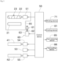
- FIG. 2 is a block diagram of the yarn winding machine 1.
- upstream or downstream in a yarn running direction may simply be referred to as “upstream” or “downstream”.
- FIG. 1 An unillustrated spinning machine is arranged upstream of the yarn winding machine 1 illustrated in FIG. 1 .
- the spinning machine produces a yarn 93 and supplies such a yarn 93 to the yarn winding machine 1.
- the yarn winding machine 1 winds the yarn 93 the on a first bobbin 91 or a second bobbin 92 to produce a package 94.
- FIG. 1 illustrates a state where the yarn 93 is wound on the first bobbin 91 to form a yarn layer so that the package 94 is produced.
- the second bobbin 92 is in an empty bobbin state where the yarn 93 is not wound yet.
- the yarn 93 is an elastic yarn such as spandex.
- the type of yarn 93 is not limited to an elastic yarn, and a synthetic yarn including nylon, polyester, or the like may be used.
- the yarn 93 includes a plurality of the yarns 93, and the yarn winding machine 1 is supplied with the plurality of yarns 93 arranged in the axial direction of the package 94, from the spinning machine.
- the first bobbin 91 includes a plurality of the first bobbins 91, and the plurality of first bobbins 91 are arranged to be aligned in the axial direction of the package 94.
- the yarn winding machine 1 winds each of the plurality of yarns 93 on the first bobbins 91 to produce the package 94 including a plurality of the packages 94.
- the yarn winding machine 1 will be described in detail below. As illustrated in FIG. 1 , the yarn winding machine 1 includes a frame 11, a first housing 20, a second housing 30, and a turret plate (bobbin holder moving mechanism) 40.
- the frame 11 is a member that holds each component provided in the yarn winding machine 1.
- the first housing 20 is attached with a traverse device 21.
- the traverse device 21 reciprocating in a winding width direction (axial direction of the package 94) with a traverse guide 23 described later being engaged with the yarn 93, each yarn 93 forwarded downstream is traversed.
- a yarn layer is formed on the first bobbin 91 or the second bobbin 92.
- the traverse device 21 includes a traverse cam 22 and the traverse guide 23.
- the traverse cam 22 is a roller-shaped member arranged parallel to the first bobbin 91 and the second bobbin 92.
- a spiral cam groove is formed on an outer peripheral surface of the traverse cam 22.
- the traverse cam 22 is rotationally driven by a traverse motor 51.
- the traverse motor 51 is controlled by a control device 50.
- the control device 50 includes a CPU, a ROM, and a RAM.
- the CPU executes various controls related to the yarn winding machine 1 by reading a program stored in the ROM into the RAM and executing such a program.
- the traverse guide 23 is a part that engages the yarn 93.
- a distal end of the traverse guide 23 includes, for example, a substantially U-shaped guide part that engages with the yarn 93 while sandwiching the yarn 93 in the winding width direction.
- a proximal end of the traverse guide 23 is positioned in a cam groove of the traverse cam 22.
- the second housing 30 is rotatably attached with a contact roller 31.
- the contact roller 31 is driven to rotate with a contact with the yarn layer of the package 94 with a predetermined pressure to forward the yarn 93 from the traverse guide 23 to the yarn layer of the package 94 and form a yarn layer shape of the package 94 into a shape.
- the contact roller 31 may be rotationally driven by using a drive unit such as a motor.
- An operation panel 32 is provided on the second housing 30.
- the operation panel 32 is a device operated by an operator.
- the operator applies an instruction to the yarn winding machine 1 by operating the operation panel 32. Examples of the instruction applied by the operator include starting winding, stopping winding, and changing a winding condition.
- the yarn winding machine 1 includes a lifting and lowering device 60.
- the lifting and lowering device 60 lifts and lowers the first housing 20 and the second housing 30 all together.
- the first housing 20 and the second housing 30 are attached to a lifting and lowering member 65.
- a ball nut 61 is attached to the lifting and lowering member 65.
- a screw rod 62 is attached to the frame 11.
- the lifting and lowering motor 63 is controlled by the control device 50. It is noted that the lifting and lowering device 60 may be realized by using a cylinder instead of the ball screw.
- the turret plate 40 is a disk-shaped member.
- the turret plate 40 is rotatably attached to the frame 11.
- a rotation axis of the turret plate 40 is at a center position of the turret plate 40.
- the turret plate 40 is rotationally driven by a turret motor 53 illustrated in FIG. 2 .
- the turret motor 53 is controlled by the control device 50.
- a first bobbin holder 41 and a second bobbin holder 42 are each provided.
- the first bobbin holder 41 is attachable with the first bobbin 91 including a plurality of the first bobbins 91 to be aligned in the axial direction.
- the second bobbin holder 42 is attachable with the second bobbin 92 including a plurality of the second bobbins 92 to be aligned in the axial direction.
- the first bobbin holder 41 is rotatable with respect to the turret plate 40 with the axial position of the first bobbin holder 41 being the center of rotation.
- the first bobbin holder 41 is rotationally driven by a first bobbin holder motor 54 illustrated in FIG. 2 .
- the second bobbin holder 42 is rotatable with respect to the turret plate 40 with the axial position of the second bobbin holder 42 being the center of rotation.
- the second bobbin holder 42 is rotationally driven by a second bobbin holder motor 55 illustrated in FIG. 2 .
- the first bobbin holder motor 54 and the second bobbin holder motor 55 are controlled by the control device 50.
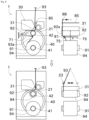
- a position of the first bobbin holder 41 at a higher position is a winding position
- a position of the second bobbin holder 42 at a lower position is a standby position.
- the yarn winding machine 1 winds the yarn 93 on the first bobbin 91 of the first bobbin holder 41 at the winding position to produce the package 94.
- the turret plate 40 rotates and the positions of the first bobbin holder 41 and the second bobbin holder 42 are switched. Thereafter, after the full winding is achieved in the package 94, the package 94 of the first bobbin holder 41 at the standby position is collected, and the yarn 93 is wound on the second bobbin 92 of the second bobbin holder 42 at the winding position.
- the first bobbin holder 41 from which the package 94 is collected is newly attached with the first bobbin 91.
- a time (period) from a state where the yarn 93 is rewound on the first bobbin 91 to produce the package 94 to a state where the yarn 93 is rewound on the second bobbin 92 to produce the package 94 is referred below to as "bobbin switching time".
- the yarn winding machine 1 includes a winding device 71.
- the winding device 71 performs a winding operation during the bobbin switching time. In the winding operation, as illustrated in the upper part of FIG. 8 described later, when the winding device 71 acts on a connecting yarn 93a stretched between the first bobbin 91 and the second bobbin 92 (the winding device 71 depresses the connecting yarn 93a), the yarn 93 is wound on the second bobbin 92 with a predetermined angle.
- the winding device 71 includes an unillustrated actuator (a cylinder, a solenoid, a motor, or the like) that performs the winding operation.
- the actuator of the winding device 71 is controlled by the control device 50. This enables a distal end (part depressing the connecting yarn 93a) of the winding device 71 to move between an operating position at which the connecting yarn 93a is depressed and a retracted position retracted from the operating position.
- the distal end of the winding device 71 is attached with a restriction guide 75.
- the restriction guide 75 restricts a position of the connecting yarn 93a before completing an operation of removing the yarn from the traverse device 21 by a yarn removing device 85 described later.
- the restriction guide 75 includes a wall part 76 and an auxiliary part 77.
- the restriction guide 75 includes a pair of the restriction guides 75 provided for each of the bobbins 91 and 92 attached to the bobbin holders 41 and 42.
- the wall part 76 includes two wall parts 76 provided for each of the bobbins 91 and 92, and the two wall parts 76 are positioned to face each other. Positions of the two wall parts 76 (more specifically, the position of the wall surface) are restriction positions. As illustrated in FIG. 4 , a region where the yarn 93 is wound in the first bobbin 91 is referred to as "yarn layer region". In the axial direction of the package 94, within the yarn layer region, the two restriction positions of the wall parts 76 are positioned. More particularly, the two restriction guides 75 (wall parts 76) are each provided to correspond to both sides (that is, one side and the other side from the center, more particularly, both ends) of the yarn layer region.
- each of the restriction guides 75 (wall part 76) restricts the yarn 93 wound on the first bobbin 91 to within the yarn layer region (prevents the yarn 93 from moving beyond the yarn layer region).
- the "end” as used herein is a term indicating not only an end point of such an end but also an area in the vicinity of such an end.
- the auxiliary part 77 is a portion that guides the connecting yarn 93a to be positioned inside the two wall parts 76.
- the auxiliary part 77 is provided in a range from each of the wall parts 76 to a position outside of the wall part 76 and beyond the yarn layer region in the axial direction of the package 94.
- the auxiliary part 77 has a portion that slopes or curves closer to the winding device 71 as the auxiliary part 77 approaches the center of the yarn layer region in the axial direction of the package 94.
- the auxiliary part 77 guides the yarn 93 wound on the first bobbin 91 to the inside of the two wall parts 76.
- the connecting yarn 93a approaches the restriction guide 75.
- the connecting yarn 93a contacts the auxiliary part 77 (that is, if the position of the connecting yarn 93a exceeds the outside of the wall part 76), the connecting yarn 93a is guided along an inclined surface of the auxiliary part 77. As a result, the connecting yarn 93a is guided inside the two wall parts 76. It is noted that not to damage the yarn 93 when the connecting yarn 93a is guided, a boundary between the auxiliary part 77 and the wall part 76 is chamfered in an arc shape.
- the plurality of restriction guides 75 of this embodiment are connected to a proximal end 74.
- the proximal end 74 and the plurality of restriction guides 75 are integrally formed, and further, are configured as a single plate-like member.
- the individual restriction guides 75 may be each attached to the winding device 71.
- a shape of each restriction guide 75 of this embodiment is an example, and may be changed as appropriate.
- the auxiliary part 77 may be omitted.
- the distal end of the winding device 71 is further attached with a cutting device 81.
- the cutting device 81 is a device that cuts the connecting yarn 93a after the yarn 93 is wound on the second bobbin 92 by the winding device 71.
- the cutting device 81 includes a fixed blade 82 and a movable blade 83.
- the cutting device 81 includes an unillustrated actuator that moves the movable blade 83.
- the cutting device 81 cuts the yarn 93 by sandwiching the yarn 93 between the fixed blade 82 and the movable blade 83.
- the actuator of the cutting device 81 is controlled by the control device 50.
- the cutting device 81 includes a plurality of cutting devices 81 each one of which is arranged in each of the bobbin 91 and 92 attached to the bobbin holders 41 and 42.
- a position where the cutting device 81 is provided is a position where it is possible to cut the yarn 93 extending from a yarn catching part 92a described later to the wall part 76 on a side of the yarn catching part 92a.
- the cutting device 81 and the restriction guide 75 of this embodiment are fastened together to the winding device 71.
- a mounting hole of the cutting device 81, a mounting hole of the restriction guide 75, and a mounting hole of the winding device 71 are fastened together with bolts or the like.
- the cutting device 81 and the restriction guide 75 may be individually attached to the winding device 71.
- the cutting device 81 of this embodiment is an example, and may be configured so that the fixed blade 82 and the movable blade 83 are not separated.
- the slit-shaped yarn catching part 92a is formed (in much the same way as in the first bobbin 91).
- the yarn catching part 92a is used so that the second bobbin 92 catches the yarn 93 between the first bobbin 91 separated from the contact roller 31 and the contact roller 31 during the bobbin switching time.
- the yarn catching part 92a is generally used when the package 94 formed of a relatively thick elastic yarn having high stretchability is produced. It is noted that the yarn catching part 92a may not be provided and may be omitted. In such a case, the yarn 93 forms straight winding on the second bobbin 92 to fix the yarn 93 to the second bobbin 92.
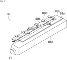
- the yarn pulling device 88 As illustrated in FIG. 3 , above the traverse device 21, a yarn pulling device 88 is arranged. During the bobbin switching time, the yarn pulling device 88 pulls the yarn 93 between the first bobbin 91 separated from the contact roller 31 and the contact roller 31, to the yarn catching part 92a of the second bobbin 92, after the yarn removing device 85 described later removes the yarn 93 from the traverse guide 23. As illustrated in FIG. 5 , the yarn pulling device 88 includes a base plate 88a, a slide plate 88c, a yarn pulling member 88d including a plurality of the yarn pulling members 88d, and a driving device 88e.
- the base plate 88a is formed with a slide hole 88b.
- the slide plate 88c is configured to be slidable along the slide hole 88b with respect to the base plate 88a.
- the slide plate 88c is fixed with the yarn pulling member 88d including the plurality of the yarn pulling members 88d at regular intervals.
- each of the yarn pulling members 88d pulls the plurality of yarns 93 arranged to be aligned in the winding width direction toward the yarn catching part 92a.
- the driving device 88e is a cylinder of which the proximal end (piston side) is fixed to the base plate 88a and of which the distal end (rod side) is fixed to the slide plate 88c.
- the driving device 88e When the driving device 88e expands and contracts, it is possible to operate the slide plate 88c (yarn pulling member 88d) with respect to the base plate 88a.
- the driving device 88e is controlled by the control device 50.
- the yarn pulling device 88 described above is an example, and the yarn pulling device 88 may be realized with a different configuration.
- FIG. 7 a state where the yarn 93 is wound on the first bobbin 91 of the first bobbin holder 41 to produce the package 94, is illustrated.
- the traverse device 21 traverses the yarn 93 to be wound on the first bobbin 91.
- the contact roller 31 contacts the first bobbin 91 (package 94) and forwards the yarn 93 traversed by the traverse device 21 to the first bobbin 91 (package 94).
- the yarn 93 is wound on the first bobbin 91 to produce the package 94.
- the control device 50 determines whether full winding is achieved in the package 94 of the first bobbin holder 41 (S 101).
- the control device 50 determines whether full winding is achieved in the package 94, based on a detection value of a sensor that detects the position of the contact roller 31 or the like or a sensor that detects a winding length of the yarn 93 along with thickening due to the winding of the package 94.
- control device 50 controls the lifting and lowering device 60 to lift the first housing 20 and the second housing 30 (S102).
- the control device 50 switches from a state where the second bobbin 92 is separated from the contact roller 31 and the first bobbin 91 (package 94) contacts the contact roller 31 to wind the yarn 93 on the first bobbin 91 to produce the package 94 to a state where the first bobbin 91 is separated from the contact roller 31 or the second bobbin 92 (package 94) contacts the contact roller 31 to wind the yarn 93 on the second bobbin 92 to produce the package 94.
- the control device 50 controls the turret motor 53 to switch the positions of the first bobbin holder 41 and the second bobbin holder 42 (S103).
- the second bobbin holder 42 is positioned at the winding position, and the first bobbin holder 41 is positioned at the standby position.
- a state where the process at step S 103 is completed is illustrated. As illustrated in such a part, when the positions of the two bobbins are switched, the yarn 93 is stretched between the first bobbin 91 (package 94) and the second bobbin 92. As described above, such a yarn 93 corresponds to the connecting yarn 93a.
- control device 50 controls the lifting and lowering device 60 to lower the first housing 20 and the second housing 30 (S104). As a result, the contact roller 31 contacts the second bobbin 92 of the second bobbin holder 42.
- the control device 50 controls the winding device 71 so that the winding device 71 performs the winding operation (S105).
- the distal end of the winding device 71 depresses the connecting yarn 93a to lengthen a contact length of the yarn 93 relative to the second bobbin 92.
- the yarn 93 is wound on the second bobbin 92.
- FIG. 8 a state obtained after the winding device 71 performs the winding operation, is illustrated. As described above, the distal end of the winding device 71 is attached with the restriction guide 75.
- the yarn 93 wound on the first bobbin 91 is restricted to within the yarn layer region of the first bobbin 91 in the axial direction of the package 94.
- the restriction guide 75 restricts a part of the yarn 93 closer to the first bobbin 91, out of the yarn 93 between the first bobbin 91 separated from the contact roller 31 and the contact roller 31.
- the yarn 93 in a space (space indicated by symbol A) on a side of the first bobbin 91 from the center in a perpendicular direction in a space between the contact roller 31 and the first bobbin 91 (package 94) is restricted by the restriction guide 75.
- the control device 50 controls the yarn removing device 85 to remove the yarn 93 from the traverse device 21 (S106). That is, the restriction of the yarn 93 by the restriction guide 75 is performed before the yarn removing device 85 completes an operation of removing the yarn 93 from the traverse device 21.
- the yarn removing device 85 is configured to remove the yarn 93 from the traverse guide 23 by depressing the yarn 93 toward the second housing 30 to deviate a yarn path.
- the yarn 93 is wound on the second bobbin 92 and the yarn 93 is restricted to within the yarn layer region of the first bobbin 91. Therefore, even if the yarn 93 is removed from the traverse guide 23, the yarn 93 does not fall outside in the winding width direction of the package 94.
- the control device 50 controls the yarn pulling device 88 to pull the yarn 93 toward the yarn catching part 92a of the second bobbin 92 (S107).
- the yarn 93 enters the yarn catching part 92a and the yarn 93 is fixed to the second bobbin 92.
- the restriction guide 75 (75 on the left side in FIG. 8 ) on a side closer to the yarn catching part 92a in the axial direction of the package 94 restricts the yarn 93 pulled toward the yarn catching part 92a to within the yarn layer region of the first bobbin 91.
- control device 50 controls the cutting device 81 to cut the connecting yarn 93a (S108).
- the switching from a state where the yarn 93 is wound on the first bobbin 91 to produce the package 94 to a state where the yarn 93 is wound on the second bobbin 92 to produce the package 94 is completed.
- control device 50 returns the yarn removing device 85 and the yarn pulling device 88 to the standby state, and then, returns the winding device 71 to the standby position to resume normal winding on the second bobbin 92 (S109).
- the yarn winding machine 1 of this embodiment includes the first bobbin holder 41, the second bobbin holder 42, the traverse device 21, the contact roller 31, the turret plate 40, the yarn removing device 85, and the restriction guide 75.
- the first bobbin holder 41 holds the first bobbin 91.
- the second bobbin holder 42 holds the second bobbin 92.
- the traverse device 21 traverses the yarn 93 to be wound on the first bobbin 91 or the second bobbin 92.
- the contact roller 31 contacts the first bobbin 91, the second bobbin 92, or the package 94, and forwards the yarn traversed by the traverse device 21 to the first bobbin 91, the second bobbin 92, or the package 94.
- the turret plate 40 changes the positions of the first bobbin holder 41 and the second bobbin holder 42 during the bobbin switching time when a state where the second bobbin 92 and the contact roller 31 are separated, the first bobbin 91 or the package 94 and the contact roller 31 are in contact to wind the yarn 93 on the first bobbin 91 to produce the package 94 is switched to a state where the first bobbin 91 and the contact roller 31 are separated, and the second bobbin 92 or the package 94 and the contact roller 31 are in contact to wind the yarn 93 on the second bobbin 92 to produce the package 94.
- the yarn removing device 85 removes the yarn 93 wound on the first bobbin 91 from the traverse device 21.
- the restriction guides 75 are each provided so as to correspond to both sides of the yarn layer region of the first bobbin 91, and before completing the operation of removing the yarn 93 from the traverse device 21 by the yarn removing device 85, restricts the yarn 93 wound on the first bobbin 91 to within the yarn layer region of the first bobbin 91 in the axial direction of the package 94.
- the yarn 93 is restricted to within the yarn layer region of the first bobbin 91 by each restriction guide 75, and thus, it is possible to prevent the yarn 93 from falling into an axial outer side of the package 94 during the bobbin switching time.
- the restriction guide 75 restricts a part on a side closer to the first bobbin 91 of the yarn 93 between the first bobbin 91 separated from the contact roller 31 and the contact roller 31.
- the yarn winding machine 1 of this embodiment includes the winding device 71 that acts on the yarn 93 between the first bobbin 91 separated from the contact roller 31 and the contact roller 31 to wind the yarn 93 on the second bobbin 92.
- the restriction guide 75 is attached to the winding device 71.
- the yarn 93 between the first bobbin 91 separated from the contact roller 31 and the contact roller 31 is wound on the second bobbin 92 by the winding device 71.
- the yarn removing device 85 removes the yarn 93 from the traverse device 21.
- the yarn 93 is restricted by the restriction guide 75 before the yarn 93 is removed from the traverse device 21, and thus, it is possible to more reliably prevent the yarn 93 from falling to the axial outer side of the package 94.
- the yarn winding machine 1 of this embodiment includes the cutting device 81 that cuts the yarn 93 between the second bobbin 92 and the first bobbin 91, after the yarn 93 between the first bobbin 91 separated from the contact roller 31 and the contact roller 31 is wound on the second bobbin 92 by the winding device 71.
- the cutting device 81 is attached to the winding device 71.
- the winding device 71 is attached with the cutting device 81 and the restriction guide 75, and thus, it is possible to arrange the members acting on the connecting yarn 93a close to one another. As a result, it is possible to simply the structure.
- the restriction guide 75 includes the wall part 76 and the auxiliary part 77.
- the wall part 76 is provided so as to be positioned within the yarn layer region of the first bobbin 91, and prevents the yarn 93 wound on the first bobbin 91 from moving beyond the yarn layer region.
- the auxiliary part 77 is provided in a range from the wall part 76 to at least the yarn layer region outside the wall part 76, and guides the yarn 93 wound on the first bobbin 91 beyond outside of the wall part 76 to inside of the wall part 76.
- the yarn 93 is guided to the inside of the wall part 76 by the auxiliary part 77, and the yarn 93 is prevented from pulling out of the wall part 76 by the wall part 76. As a result, it is possible to more reliably restrict the yarn so that the yarn 93 is positioned within the yarn layer region.
- the yarn winding machine 1 of this embodiment includes the yarn pulling device 88.
- the second bobbin 92 is formed with a slit-shaped yarn catching part 92a allowing the second bobbin 92 to catch the yarn 93 between the first bobbin 91 separated from the contact roller 31 and the contact roller 31 during the bobbin switching time.
- the yarn pulling device 88 pulls the yarn 93 between the first bobbin 91 separated from the contact roller 31 and the contact roller 31 toward the slit-shaped yarn catching part 92a.
- the restriction guide 75 on a side closer to the yarn catching part 92a restricts the yarn 93 pulled toward the slit-shaped yarn catching part 92a to within the yarn layer region of the first bobbin 91.
- one restriction guide 75 it is possible to use one of the restriction guides 75 to prevent the yarn from falling off from a yarn layer surface when the yarn is pulled. That is, one restriction guide 75 has two functions, and thus, it is possible to simplify the structure as compared to a configuration where an individual guide is provided for each function.
- the restriction guide 75 is attached to the winding device 71, but the restriction guide 75 may be attached to another member.
- an actuator that moves the restriction guide 75 toward and away from the connecting yarn 93a is arranged to independently drive the restriction guide 75 with respect to the winding device 71.
- the restriction guide 75 may immediately return to the standby position after the yarn 93 is removed by the yarn removing device 85.
- the timing at which the restriction guide 75 restricts the position of the yarn 93 is not limited to the timing indicated as an example in the above embodiment.
- the restriction guide 75 may restrict the position of the yarn 93 before the contact roller 31 and the second bobbin 92 contact each other.
- the restriction position of the restriction guide 75 is inside the end of the yarn layer region by a predetermined distance. If the restriction guide 75 is used also as a guide for preventing the yarn from falling at the yarn pulling time, when the restriction position of the restriction guide 75 is too close to the center side of the yarn layer region, the yarn 93 is far from the yarn catching part 92a, and thus, the yarn 93 is less likely to be caught by the yarn catching part 92a. Therefore, it is preferable to determine the restriction position of the restriction guide 75 in consideration of such a tendency.
- the yarn catching part 92a may not only be formed outside the yarn layer region but also formed within the yarn layer region. Even in such a case, the yarn 93 must be removed from the traverse device 21, and thus, it is possible to utilize the restriction guide 75 of the present invention. It is noted that if the yarn catching part 92a is formed in the center of the yarn layer region, it is possible to omit the yarn pulling device 88.
- the yarn 93 is cut by using the cutting device 81.
- the cutting device 81 may be omitted.
- the flowchart illustrated in the above embodiment is an example, and some of the processes may be omitted, the contents of some of the processes may be changed, or a new process may be added.
- a subsequent process may be started before one process is completed. For example, after the connecting yarn 93a is guided to the restriction guide 75 at the distal end of the winding device 71, the yarn removing device 85 may be operated before the winding operation of the winding device 71 is completed.
- the traverse device 21 of the above embodiment is of cam drum type, the traverse device 21 may have a different configuration as long as it is possible to reciprocate the traverse guide 23 in the winding width direction.
- a belt-type traverse device instead of the traverse device 21, may be used.
Landscapes
- Engineering & Computer Science (AREA)
- Textile Engineering (AREA)
- Replacing, Conveying, And Pick-Finding For Filamentary Materials (AREA)
- Guides For Winding Or Rewinding, Or Guides For Filamentary Materials (AREA)
- Filamentary Materials, Packages, And Safety Devices Therefor (AREA)
- Winding Filamentary Materials (AREA)
Applications Claiming Priority (1)
| Application Number | Priority Date | Filing Date | Title |
|---|---|---|---|
| JP2022030154A JP7733594B2 (ja) | 2022-02-28 | 2022-02-28 | 糸巻取機 |
Publications (1)
| Publication Number | Publication Date |
|---|---|
| EP4234467A1 true EP4234467A1 (de) | 2023-08-30 |
Family
ID=85283996
Family Applications (1)
| Application Number | Title | Priority Date | Filing Date |
|---|---|---|---|
| EP23157361.9A Pending EP4234467A1 (de) | 2022-02-28 | 2023-02-17 | Garnwickelmaschine |
Country Status (4)
| Country | Link |
|---|---|
| EP (1) | EP4234467A1 (de) |
| JP (1) | JP7733594B2 (de) |
| KR (1) | KR20230128969A (de) |
| CN (1) | CN116654719A (de) |
Cited By (1)
| Publication number | Priority date | Publication date | Assignee | Title |
|---|---|---|---|---|
| CN120903327A (zh) * | 2025-10-11 | 2025-11-07 | 晋江市懋鸿纺织科技有限公司 | 一种精密松筒机及其工作方法 |
Citations (6)
| Publication number | Priority date | Publication date | Assignee | Title |
|---|---|---|---|---|
| WO1994026645A1 (fr) * | 1993-05-13 | 1994-11-24 | Toray Engineering Co., Ltd. | Procede et machine d'enroulement de filament |
| JPH07268722A (ja) | 1994-03-22 | 1995-10-17 | Murata Mach Ltd | 弾性糸の紡糸巻取機 |
| EP0703179A2 (de) * | 1994-08-24 | 1996-03-27 | Maschinenfabrik Rieter Ag | Automatische Spulmaschine und Verfahren zur Übergabe des Fadens von einer vollen Spule an eine leere Hülse |
| JP2002284448A (ja) * | 2001-03-28 | 2002-10-03 | Toray Ind Inc | 合成繊維の巻取り方法及び巻取り装置 |
| KR100472688B1 (ko) * | 2002-03-27 | 2005-03-08 | 주식회사 효성 | 탄성사의 방사 권취기 및 그 권취 방법 |
| JP2010137987A (ja) * | 2008-12-09 | 2010-06-24 | Iljin A-Tech Co Ltd | 最内外層のバンチ形成を防止できる糸巻取装置およびこれを用いた糸移動方法 |
Family Cites Families (1)
| Publication number | Priority date | Publication date | Assignee | Title |
|---|---|---|---|---|
| DE102012107015A1 (de) * | 2011-08-03 | 2013-02-07 | Oerlikon Textile Gmbh & Co. Kg | Aufspulvorrichtung |
-
2022
- 2022-02-28 JP JP2022030154A patent/JP7733594B2/ja active Active
-
2023
- 2023-02-06 KR KR1020230015547A patent/KR20230128969A/ko active Pending
- 2023-02-09 CN CN202310142271.XA patent/CN116654719A/zh active Pending
- 2023-02-17 EP EP23157361.9A patent/EP4234467A1/de active Pending
Patent Citations (6)
| Publication number | Priority date | Publication date | Assignee | Title |
|---|---|---|---|---|
| WO1994026645A1 (fr) * | 1993-05-13 | 1994-11-24 | Toray Engineering Co., Ltd. | Procede et machine d'enroulement de filament |
| JPH07268722A (ja) | 1994-03-22 | 1995-10-17 | Murata Mach Ltd | 弾性糸の紡糸巻取機 |
| EP0703179A2 (de) * | 1994-08-24 | 1996-03-27 | Maschinenfabrik Rieter Ag | Automatische Spulmaschine und Verfahren zur Übergabe des Fadens von einer vollen Spule an eine leere Hülse |
| JP2002284448A (ja) * | 2001-03-28 | 2002-10-03 | Toray Ind Inc | 合成繊維の巻取り方法及び巻取り装置 |
| KR100472688B1 (ko) * | 2002-03-27 | 2005-03-08 | 주식회사 효성 | 탄성사의 방사 권취기 및 그 권취 방법 |
| JP2010137987A (ja) * | 2008-12-09 | 2010-06-24 | Iljin A-Tech Co Ltd | 最内外層のバンチ形成を防止できる糸巻取装置およびこれを用いた糸移動方法 |
Cited By (1)
| Publication number | Priority date | Publication date | Assignee | Title |
|---|---|---|---|---|
| CN120903327A (zh) * | 2025-10-11 | 2025-11-07 | 晋江市懋鸿纺织科技有限公司 | 一种精密松筒机及其工作方法 |
Also Published As
| Publication number | Publication date |
|---|---|
| KR20230128969A (ko) | 2023-09-05 |
| JP2023125831A (ja) | 2023-09-07 |
| CN116654719A (zh) | 2023-08-29 |
| JP7733594B2 (ja) | 2025-09-03 |
Similar Documents
| Publication | Publication Date | Title |
|---|---|---|
| US4108388A (en) | Method for catching, severing and rethreading a thread and an apparatus for implementing the method | |
| US5016829A (en) | Takeup machine | |
| CN101544319B (zh) | 纱线卷绕机 | |
| EP4234467A1 (de) | Garnwickelmaschine | |
| EP2105399B1 (de) | Garnwicklungsvorrichtung und Garnwicklungsverfahren | |
| EP3357847B1 (de) | Garnaufwickler, vorrichtung zur aufnahme von gesponnenem garn und verfahren zur garneinfädelung im garnaufwickler | |
| EP1995201A2 (de) | Garnaufwickler | |
| KR101213126B1 (ko) | 실 권취 장치 | |
| JP2001072338A (ja) | フィラメント糸条巻取装置における満管巻取ボビンと空巻取ボビンの交換方法とこの方法を実施するための装置 | |
| JP4395828B2 (ja) | 張力検出器を備える糸条巻取機 | |
| JP2877172B2 (ja) | 糸の巻取装置 | |
| JP7535384B2 (ja) | 繊維機械 | |
| EP4424623A1 (de) | Garnwickelmaschine | |
| EP4242155A1 (de) | Garnwickelmaschine | |
| US4098066A (en) | Open-end spinning machine | |
| JP7352379B2 (ja) | 繊維機械を稼働させる方法、および、繊維機械 | |
| JPH0881134A (ja) | 糸移行システム | |
| CN107130308B (zh) | 纺丝牵引机 | |
| EP4249414B1 (de) | Garnwickelmaschine | |
| EP4624403A1 (de) | Garnwickelvorrichtung | |
| EP4624401A1 (de) | Garnwickelvorrichtung | |
| KR20010072348A (ko) | 사조의 절환방법 및 장치 | |
| EP4624400A1 (de) | Changiervorrichtung und garnwickelvorrichtung | |
| EP0744369A1 (de) | Garnwickelmechanismus | |
| EP0323098A2 (de) | Axiale Störvorrichtung, benutzt in einem Garnwickler |
Legal Events
| Date | Code | Title | Description |
|---|---|---|---|
| PUAI | Public reference made under article 153(3) epc to a published international application that has entered the european phase |
Free format text: ORIGINAL CODE: 0009012 |
|
| STAA | Information on the status of an ep patent application or granted ep patent |
Free format text: STATUS: THE APPLICATION HAS BEEN PUBLISHED |
|
| AK | Designated contracting states |
Kind code of ref document: A1 Designated state(s): AL AT BE BG CH CY CZ DE DK EE ES FI FR GB GR HR HU IE IS IT LI LT LU LV MC ME MK MT NL NO PL PT RO RS SE SI SK SM TR |
|
| STAA | Information on the status of an ep patent application or granted ep patent |
Free format text: STATUS: REQUEST FOR EXAMINATION WAS MADE |
|
| 17P | Request for examination filed |
Effective date: 20240223 |
|
| RBV | Designated contracting states (corrected) |
Designated state(s): AL AT BE BG CH CY CZ DE DK EE ES FI FR GB GR HR HU IE IS IT LI LT LU LV MC ME MK MT NL NO PL PT RO RS SE SI SK SM TR |
|
| STAA | Information on the status of an ep patent application or granted ep patent |
Free format text: STATUS: EXAMINATION IS IN PROGRESS |
|
| 17Q | First examination report despatched |
Effective date: 20250806 |