EP4234446A2 - Dynamische leistungsverwaltung - Google Patents
Dynamische leistungsverwaltung Download PDFInfo
- Publication number
- EP4234446A2 EP4234446A2 EP23169515.6A EP23169515A EP4234446A2 EP 4234446 A2 EP4234446 A2 EP 4234446A2 EP 23169515 A EP23169515 A EP 23169515A EP 4234446 A2 EP4234446 A2 EP 4234446A2
- Authority
- EP
- European Patent Office
- Prior art keywords
- power
- charging
- storage
- container
- power consumption
- Prior art date
- Legal status (The legal status is an assumption and is not a legal conclusion. Google has not performed a legal analysis and makes no representation as to the accuracy of the status listed.)
- Withdrawn
Links
Images



Classifications
-
- G—PHYSICS
- G06—COMPUTING OR CALCULATING; COUNTING
- G06Q—INFORMATION AND COMMUNICATION TECHNOLOGY [ICT] SPECIALLY ADAPTED FOR ADMINISTRATIVE, COMMERCIAL, FINANCIAL, MANAGERIAL OR SUPERVISORY PURPOSES; SYSTEMS OR METHODS SPECIALLY ADAPTED FOR ADMINISTRATIVE, COMMERCIAL, FINANCIAL, MANAGERIAL OR SUPERVISORY PURPOSES, NOT OTHERWISE PROVIDED FOR
- G06Q10/00—Administration; Management
- G06Q10/08—Logistics, e.g. warehousing, loading or distribution; Inventory or stock management
-
- H—ELECTRICITY
- H02—GENERATION; CONVERSION OR DISTRIBUTION OF ELECTRIC POWER
- H02J—ELECTRIC POWER NETWORKS; CIRCUIT ARRANGEMENTS OR SYSTEMS FOR SUPPLYING OR DISTRIBUTING ELECTRIC POWER; SYSTEMS FOR STORING ELECTRIC ENERGY
- H02J3/00—Circuit arrangements for AC mains or AC distribution networks
-
- B—PERFORMING OPERATIONS; TRANSPORTING
- B60—VEHICLES IN GENERAL
- B60L—PROPULSION OF ELECTRICALLY-PROPELLED VEHICLES; SUPPLYING ELECTRIC POWER FOR AUXILIARY EQUIPMENT OF ELECTRICALLY-PROPELLED VEHICLES; ELECTRODYNAMIC BRAKE SYSTEMS FOR VEHICLES IN GENERAL; MAGNETIC SUSPENSION OR LEVITATION FOR VEHICLES; MONITORING OPERATING VARIABLES OF ELECTRICALLY-PROPELLED VEHICLES; ELECTRIC SAFETY DEVICES FOR ELECTRICALLY-PROPELLED VEHICLES
- B60L53/00—Methods of charging batteries, specially adapted for electric vehicles; Charging stations or on-board charging equipment therefor; Exchange of energy storage elements in electric vehicles
- B60L53/60—Monitoring or controlling charging stations
- B60L53/63—Monitoring or controlling charging stations in response to network capacity
-
- B—PERFORMING OPERATIONS; TRANSPORTING
- B60—VEHICLES IN GENERAL
- B60L—PROPULSION OF ELECTRICALLY-PROPELLED VEHICLES; SUPPLYING ELECTRIC POWER FOR AUXILIARY EQUIPMENT OF ELECTRICALLY-PROPELLED VEHICLES; ELECTRODYNAMIC BRAKE SYSTEMS FOR VEHICLES IN GENERAL; MAGNETIC SUSPENSION OR LEVITATION FOR VEHICLES; MONITORING OPERATING VARIABLES OF ELECTRICALLY-PROPELLED VEHICLES; ELECTRIC SAFETY DEVICES FOR ELECTRICALLY-PROPELLED VEHICLES
- B60L53/00—Methods of charging batteries, specially adapted for electric vehicles; Charging stations or on-board charging equipment therefor; Exchange of energy storage elements in electric vehicles
- B60L53/60—Monitoring or controlling charging stations
- B60L53/64—Optimising energy costs, e.g. responding to electricity rates
-
- B—PERFORMING OPERATIONS; TRANSPORTING
- B65—CONVEYING; PACKING; STORING; HANDLING THIN OR FILAMENTARY MATERIAL
- B65G—TRANSPORT OR STORAGE DEVICES, e.g. CONVEYORS FOR LOADING OR TIPPING, SHOP CONVEYOR SYSTEMS OR PNEUMATIC TUBE CONVEYORS
- B65G1/00—Storing articles, individually or in orderly arrangement, in warehouses or magazines
- B65G1/02—Storage devices
- B65G1/04—Storage devices mechanical
-
- B—PERFORMING OPERATIONS; TRANSPORTING
- B65—CONVEYING; PACKING; STORING; HANDLING THIN OR FILAMENTARY MATERIAL
- B65G—TRANSPORT OR STORAGE DEVICES, e.g. CONVEYORS FOR LOADING OR TIPPING, SHOP CONVEYOR SYSTEMS OR PNEUMATIC TUBE CONVEYORS
- B65G1/00—Storing articles, individually or in orderly arrangement, in warehouses or magazines
- B65G1/02—Storage devices
- B65G1/04—Storage devices mechanical
- B65G1/0492—Storage devices mechanical with cars adapted to travel in storage aisles
-
- B—PERFORMING OPERATIONS; TRANSPORTING
- B65—CONVEYING; PACKING; STORING; HANDLING THIN OR FILAMENTARY MATERIAL
- B65G—TRANSPORT OR STORAGE DEVICES, e.g. CONVEYORS FOR LOADING OR TIPPING, SHOP CONVEYOR SYSTEMS OR PNEUMATIC TUBE CONVEYORS
- B65G1/00—Storing articles, individually or in orderly arrangement, in warehouses or magazines
- B65G1/02—Storage devices
- B65G1/04—Storage devices mechanical
- B65G1/137—Storage devices mechanical with arrangements or automatic control means for selecting which articles are to be removed
- B65G1/1373—Storage devices mechanical with arrangements or automatic control means for selecting which articles are to be removed for fulfilling orders in warehouses
-
- G—PHYSICS
- G06—COMPUTING OR CALCULATING; COUNTING
- G06F—ELECTRIC DIGITAL DATA PROCESSING
- G06F1/00—Details not covered by groups G06F3/00 - G06F13/00 and G06F21/00
- G06F1/26—Power supply means, e.g. regulation thereof
-
- H—ELECTRICITY
- H02—GENERATION; CONVERSION OR DISTRIBUTION OF ELECTRIC POWER
- H02J—ELECTRIC POWER NETWORKS; CIRCUIT ARRANGEMENTS OR SYSTEMS FOR SUPPLYING OR DISTRIBUTING ELECTRIC POWER; SYSTEMS FOR STORING ELECTRIC ENERGY
- H02J3/00—Circuit arrangements for AC mains or AC distribution networks
- H02J3/008—Circuit arrangements for power supply or distribution technologies responsive to energy trading
-
- H—ELECTRICITY
- H02—GENERATION; CONVERSION OR DISTRIBUTION OF ELECTRIC POWER
- H02J—ELECTRIC POWER NETWORKS; CIRCUIT ARRANGEMENTS OR SYSTEMS FOR SUPPLYING OR DISTRIBUTING ELECTRIC POWER; SYSTEMS FOR STORING ELECTRIC ENERGY
- H02J3/00—Circuit arrangements for AC mains or AC distribution networks
- H02J3/28—Arrangements for balancing of the load in networks by storage of energy
- H02J3/32—Arrangements for balancing of the load in networks by storage of energy using batteries or super capacitors with converting means
-
- H—ELECTRICITY
- H02—GENERATION; CONVERSION OR DISTRIBUTION OF ELECTRIC POWER
- H02J—ELECTRIC POWER NETWORKS; CIRCUIT ARRANGEMENTS OR SYSTEMS FOR SUPPLYING OR DISTRIBUTING ELECTRIC POWER; SYSTEMS FOR STORING ELECTRIC ENERGY
- H02J3/00—Circuit arrangements for AC mains or AC distribution networks
- H02J3/28—Arrangements for balancing of the load in networks by storage of energy
- H02J3/32—Arrangements for balancing of the load in networks by storage of energy using batteries or super capacitors with converting means
- H02J3/322—Arrangements for balancing of the load in networks by storage of energy using batteries or super capacitors with converting means the battery being on-board an electric or hybrid vehicle, e.g. vehicle to grid arrangements [V2G], power aggregation, use of the battery for network load balancing, coordinated or cooperative battery charging
-
- B—PERFORMING OPERATIONS; TRANSPORTING
- B65—CONVEYING; PACKING; STORING; HANDLING THIN OR FILAMENTARY MATERIAL
- B65G—TRANSPORT OR STORAGE DEVICES, e.g. CONVEYORS FOR LOADING OR TIPPING, SHOP CONVEYOR SYSTEMS OR PNEUMATIC TUBE CONVEYORS
- B65G1/00—Storing articles, individually or in orderly arrangement, in warehouses or magazines
- B65G1/02—Storage devices
- B65G1/04—Storage devices mechanical
- B65G1/0464—Storage devices mechanical with access from above
-
- B—PERFORMING OPERATIONS; TRANSPORTING
- B65—CONVEYING; PACKING; STORING; HANDLING THIN OR FILAMENTARY MATERIAL
- B65G—TRANSPORT OR STORAGE DEVICES, e.g. CONVEYORS FOR LOADING OR TIPPING, SHOP CONVEYOR SYSTEMS OR PNEUMATIC TUBE CONVEYORS
- B65G1/00—Storing articles, individually or in orderly arrangement, in warehouses or magazines
- B65G1/02—Storage devices
- B65G1/04—Storage devices mechanical
- B65G1/0478—Storage devices mechanical for matrix-arrangements
-
- H—ELECTRICITY
- H02—GENERATION; CONVERSION OR DISTRIBUTION OF ELECTRIC POWER
- H02J—ELECTRIC POWER NETWORKS; CIRCUIT ARRANGEMENTS OR SYSTEMS FOR SUPPLYING OR DISTRIBUTING ELECTRIC POWER; SYSTEMS FOR STORING ELECTRIC ENERGY
- H02J2101/00—Supply or distribution of decentralised, dispersed or local electric power generation
- H02J2101/20—Dispersed power generation using renewable energy sources
-
- Y—GENERAL TAGGING OF NEW TECHNOLOGICAL DEVELOPMENTS; GENERAL TAGGING OF CROSS-SECTIONAL TECHNOLOGIES SPANNING OVER SEVERAL SECTIONS OF THE IPC; TECHNICAL SUBJECTS COVERED BY FORMER USPC CROSS-REFERENCE ART COLLECTIONS [XRACs] AND DIGESTS
- Y02—TECHNOLOGIES OR APPLICATIONS FOR MITIGATION OR ADAPTATION AGAINST CLIMATE CHANGE
- Y02T—CLIMATE CHANGE MITIGATION TECHNOLOGIES RELATED TO TRANSPORTATION
- Y02T10/00—Road transport of goods or passengers
- Y02T10/60—Other road transportation technologies with climate change mitigation effect
- Y02T10/70—Energy storage systems for electromobility, e.g. batteries
-
- Y—GENERAL TAGGING OF NEW TECHNOLOGICAL DEVELOPMENTS; GENERAL TAGGING OF CROSS-SECTIONAL TECHNOLOGIES SPANNING OVER SEVERAL SECTIONS OF THE IPC; TECHNICAL SUBJECTS COVERED BY FORMER USPC CROSS-REFERENCE ART COLLECTIONS [XRACs] AND DIGESTS
- Y02—TECHNOLOGIES OR APPLICATIONS FOR MITIGATION OR ADAPTATION AGAINST CLIMATE CHANGE
- Y02T—CLIMATE CHANGE MITIGATION TECHNOLOGIES RELATED TO TRANSPORTATION
- Y02T10/00—Road transport of goods or passengers
- Y02T10/60—Other road transportation technologies with climate change mitigation effect
- Y02T10/7072—Electromobility specific charging systems or methods for batteries, ultracapacitors, supercapacitors or double-layer capacitors
-
- Y—GENERAL TAGGING OF NEW TECHNOLOGICAL DEVELOPMENTS; GENERAL TAGGING OF CROSS-SECTIONAL TECHNOLOGIES SPANNING OVER SEVERAL SECTIONS OF THE IPC; TECHNICAL SUBJECTS COVERED BY FORMER USPC CROSS-REFERENCE ART COLLECTIONS [XRACs] AND DIGESTS
- Y02—TECHNOLOGIES OR APPLICATIONS FOR MITIGATION OR ADAPTATION AGAINST CLIMATE CHANGE
- Y02T—CLIMATE CHANGE MITIGATION TECHNOLOGIES RELATED TO TRANSPORTATION
- Y02T90/00—Enabling technologies or technologies with a potential or indirect contribution to GHG emissions mitigation
- Y02T90/10—Technologies relating to charging of electric vehicles
- Y02T90/12—Electric charging stations
Definitions
- the present invention regards a system and a method for managing power consumption of an automated storage and retrieval system, and more particularly a system and method for managing power consumption of an automated storage and retrieval system by providing a modified operation of the automated storage and retrieval system during periods of lower power availability.
- Fig. 1 discloses a typical prior art automated storage and retrieval system 1 with a framework structure 100 and Fig. 2 and 3 discloses two different prior art container handling vehicles 201, 301 suitable for operating on such a system 1.
- the framework structure 100 comprises several upright members 102 and several horizontal members 103 which are supported by the upright members 102.
- the members 102, 103 may typically be made of metal, e.g. extruded aluminum profiles.
- the framework structure 100 defines a storage grid 104 comprising storage columns 105 arranged in rows, in which storage columns 105 storage containers 106, also known as bins, are stacked one on top of another to form stacks 107.
- the storage grid 104 guards against horizontal movement of the stacks 107 of storage containers 106, and guides vertical movement of the containers 106, but does normally not otherwise support the storage containers 106 when stacked.
- Each prior art container handling vehicle 201, 301 comprises a storage compartment or space for receiving and stowing a storage container 106 when transporting the storage container 106 across the rail system 108.
- the storage space may comprise a cavity arranged centrally within the vehicle body 201a as shown in Fig. 2 and as described in e.g. WO2015/193278A1 .
- FIG. 3 shows an alternative configuration of a container handling vehicle 301 with a cantilever construction. Such a vehicle is described in detail in e.g. NO317366 .
- a grid 104 In a storage grid 104, most of the grid columns 112 are storage columns 105, i.e. grid columns 105 where storage containers 106 are stored in stacks 107.
- a grid 104 normally has at least one grid column 112 which is used not for storing storage containers 106, but which comprises a location where the container handling vehicles 201, 301 can drop off and/or pick up storage containers 106 so that they can be transported to an access station (not shown) where the storage containers 106 can be accessed from outside of the grid 104 or transferred out of or into the grid 104.
- such a location is normally referred to as a 'port' and the grid column 112 in which the port is located may be referred to as a ⁇ port column' 119, 120.
- the transportation to the access station may be in any direction, that is horizontal, tilted and/or vertical.
- the storage containers 106 may be placed in a random or dedicated grid column 112 within the storage grid 104, then picked up by any container handling vehicle and transported to a port 119, 120 for further transportation to an access station.
- the term 'tilted' means transportation of storage containers 106 having a general transportation orientation somewhere between horizontal and vertical.
- one of the container handling vehicles 201, 301 is instructed to retrieve the target storage container 106 from its position in the grid 104 and transport it to the drop-off port 119.
- This operation involves moving the container handling vehicle 201, 301 to a grid location above the storage column 105 in which the target storage container 106 is positioned, retrieving the storage container 106 from the storage column 105 using the container handling vehicle's 201, 301 lifting devices (not shown), and transporting the storage container 106 to the drop-off port 119. If the target storage container 106 is located deep within a stack 107, i.e.
- the operation also involves temporarily moving the above-positioned storage containers prior to lifting the target storage container 106 from the storage column 105.
- This step which is sometimes referred to as "digging" within the art, may be performed with the same container handling vehicle that is subsequently used for transporting the target storage container to the drop-off port 119, or with one or a plurality of other cooperating container handling vehicles.
- the automated storage and retrieval system 1 may have container handling vehicles specifically dedicated to the task of temporarily removing storage containers from a storage column 105. Once the target storage container 106 has been removed from the storage column 105, the temporarily removed storage containers can be repositioned into the original storage column 105. However, the removed storage containers may alternatively be relocated to other storage columns.
- one of the container handling vehicles 201, 301 is instructed to pick up the storage container 106 from the pick-up port 120 and transport it to a grid location above the storage column 105 where it is to be stored.
- the container handling vehicle 201, 301 positions the storage container 106 at the desired position. The removed storage containers may then be lowered back into the storage column 105 or relocated to other storage columns.
- the automated storage and retrieval system 1 For monitoring and controlling the automated storage and retrieval system 1, e.g. monitoring and controlling the location of respective storage containers 106 within the grid 104, the content of each storage container 106, and the movement of the container handling vehicles 201, 301 so that a desired storage container 106 can be delivered to the desired location at the desired time without the container handling vehicles 201, 301 colliding with each other, the automated storage and retrieval system 1 comprises a control system which typically is computerized and which typically comprises a database for keeping track of the storage containers 106.
- a storage system like the one described above consumes energy through e.g. charging of the power sources in the container handling vehicles.
- the charging of these power sources usually Li-ion batteries, can happen on any given time of day since a storage system like this can be operative 24 hours a day all year around. If it is a large storage system with lots of container handling vehicles this can require a large amount of consumed energy.
- solar cells only work optimally during day time and if the weather conditions are right. Otherwise, the amount of power received from these types of sources is not reliable.
- Solar cells also have limited effect at certain places of the globe and at certain times of the year.
- Other local renewable power sources like wind mills and water turbines, also have limitations. They are dependent on location and weather conditions to work.
- the solution is therefore to install a power monitoring device in the power supply to always keep track of the available power.
- This information is communicated to the system which can adapt its power consumption accordingly.
- the system can also keep track of the periods of insufficient power supply to see if there are certain recurring periods during the day where there are insufficient power available.
- the system can use this information to adapt the power consumption to fit an upcoming period of low power supply. This can be to reduce the speed of the vehicles prior to a period of low power supply to extend the range of the battery on the vehicle and to charge batteries on vehicles before they normally would be charged.
- Fig. 1 is a perspective view of a grid of a prior art automated storage and retrieval system. It is disclosed a typical prior art automated storage and retrieval system 1 with a framework structure 100.
- the framework structure 100 comprises several upright members 102 and several horizontal members 103 which are supported by the upright members 102.
- the members 102, 103 may typically be made of metal, e.g. extruded aluminum profiles.
- the framework structure 100 defines a storage grid 104 comprising storage columns 105 arranged in rows, in which storage columns 105 storage containers 106, also known as bins, are stacked one on top of another to form stacks 107.
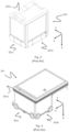
- Fig. 2 is a perspective view of a prior art container handling vehicle having a centrally arranged cavity for containing storage containers therein.
- Fig. 2 and 3 discloses two different prior art container handling vehicles 201, 301 suitable for operating on such a system 1.
- Each prior art container handling vehicle 201, 301 comprises a storage compartment or space for receiving and stowing a storage container 106 when transporting the storage container 106 across the rail system 108.
- the storage space may comprise a cavity arranged centrally within the vehicle body 201a.
- Fig. 3 is a perspective view of a prior art container handling vehicle having a cantilever for containing storage containers underneath. It is shown an alternative configuration of a container handling vehicle 301 with a cantilever construction.
- FIG. 4 is a box drawing of how the different parts of the system are connected.
- a power supply 401 provides the storage system with power to operate.
- the power can come from an ordinary power grid or from locally deployed renewable power sources, or both.
- the locally deployed power sources are most likely solar cells, but they can also be wind turbines or water turbines.
- a power monitoring device 402 is mounted to the power supply 401.
- the power monitoring device 402 constantly monitors the amount of available power from the grid. A reading of the amount of available power is sent to the control system 403.
- the control system 403 keeps track of whether there are certain periods during the day where the power supply 401 is not sufficient to power the entire system. If a period like this is expected, the control system 403 will adjust the power consumption of the system in order to not overload the power supply 401.
- control system 403 can modify the power consumption.
- the control system 403 can modify the power consumption by reducing the charging effect of the charging station(s) 404. If the charging station(s) 404 charge the batteries with reduced effect, the power consumption is reduced.
- An alternative solution is to modify the speed of the container handling vehicles 201, 301.
- the reduction in speed ensures that the rechargeable batteries on the container handling vehicles 201, 301 last longer before having to be recharged.
- both these strategies can be used at the same time.
- the power consumption can also be modified to accommodate for fluctuations in power prices during the day, e.g. if there are periods during the day when the prices are high.
- An algorithm determines if one or both solutions to reduce the power consumption of the storage system is to be used, and the decision is based on the historical data of when the power supply is not sufficient and the information from the power monitoring device regarding the amount of power available.
- the two different techniques for reducing the power consumption can be used together or separately depending on the circumstances for the drop in available power.
- the algorithm determines which solution is to be used depending on different factors like drop in available power whether it is anticipated or not, the degree of severity and how long the surge has lasted or is expected to last.
- One solution is to reduce the charging effect but maintain the operating speed of the container handling vehicles.
- This solution results in a sudden drop in power consumption and is ideal for dealing with an unanticipated drop in power availability.
- this method can be used for dealing with a short and anticipated drop in power availability.
- the surplus of power can be used to top up the rechargeable power sources.
- both the reduction of the charging effect and the reduction in the speed of the container handling vehicle 201, 301 can be effectuated.
- This solution is effective if there is an anticipated drop in available power that is expected to last for a longer period of time, e.g. several hours.
- a third alternative is to keep the charging effect of the charging station at 100% but reduce the speed of the container handling vehicles. This alternative is effective if there is an anticipated drop in available power where there is a need for having as many fully charged batteries ready as possible when the available power drops.
- the container handling vehicles 201, 301 can reduce their speed and the charging station(s) 404 can reduce their charging effect after a while. This solution is preferable if there is an anticipated power drop that is expected to last for a long time. In this solution the container handling vehicles 201, 301 conserve their energy and the charging effect is maximized until the drop of power availability occurs.
- the charging system comprises a plurality of chargers connected in a charging group. There can be several such charging groups in an entire system.
- a charging group is defined by a group of chargers connected to the same supply circuit.
- the control system 403 can optimize and distribute the load between the charging groups. Further the control system can optimize and distribute the load inside a charging group by adjusting the charging profile of each charger. This is to optimize the use of the available power for each charging group.
- the available power is optimized based on known operations and tasks and future tasks given by experience data acquired from an experience model.
- the optimization and distribution of the load between the charging groups is done by monitoring the available power for each charging group. This is done by communicating the available effect for the circuit that supplies the individual charging group. Alternatively, the available power can be set statistically for each charging group without regular updating of actual available power.
- each charger included in each charging group is monitored.
- the energy requirement will depend on whether the charger is active and where in the charging process it is. By evaluating the data from each charger, it is possible to estimate the future needed effect for the charger in question.
- the system's current and future energy needs is evaluated. This is done based on the current energy level, the activity and future tasks for the system, current and future needs in the charging groups and the energy requirement for the system is based on experience models. Experience data is used to update the model.
- the distribution of load between the charging groups is optimized by using current and estimated future energy needs for each single charge group to distribute new charge tasks between the groups.
- the use within a charging group is optimized by adjusting the charging profile of each individual charger.
- the charging groups available power is continually monitored, and the available power is always distributed between the individual chargers.
- the estimated future effect needed for each individual charger is also taken into account when adjusting the consumption internally in the charging group.
- the control system will continuously update the experience model and the algorithms based on historical data.
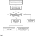
- Fig. 5 is a flowchart of the process for monitoring and adjusting the power consumption according to the present invention.
- the power monitoring device 402 monitors the available power from the power supply 401.
- the power supply 401 can be either a power grid solution or local renewable power sources like solar cells or similar. Most likely the power supply 401 will either be power from the power grid or a combination of grid power and power from local renewable power sources.
- the power monitoring device 402 communicates the available power to the control system 403. These data are stored in an experience model and provides the basis for how the control system handles future drops in available power.
- the control system 403 can execute measures both for handling a sudden drop in available power as well as anticipating future shortage of power.
- the control system evaluates if the available power is sufficient to power the entire storage system. If it is sufficient, the operation continues at the current level. If it is not sufficient the control system can initiate actions for reducing the power consumption of the system.
- control system can modify the speed at which the container handling vehicles operate.
- a modification in speed might be to reduce the speed of the container handling vehicles with up to 50% thus allowing a fully charged container handling vehicle to operate for twice as long without having to recharge the batteries.
- control system keeps track of the periods where there is a drop in available power. These data are stored in an experience model, so the control system can anticipate when there is a drop in available power in order to adjust the power consumption ahead of time.
- the charging system is comprised by a plurality of chargers connected in a charging group. There can be several such charging groups in an entire system.
- a charging group is defined by a group of chargers connected to the same supply circuit.
- the charging effect within a charging group can be optimized by having some chargers working with full capacity and allowing other chargers either to work with reduced capacity or completely shut off.
- the internal division of capacity is decided by the tasks the chargers are performing, but also the tasks that the chargers are intended to perform.
- the distribution of the load between the different charging groups is done by monitoring the available power for each charging group and communicating the available effect for the circuit that supplies the individual charging groups.
- Fig. 6 is a diagram showing an example of the present invention in use.
- this example there is a storage system using three container handling vehicles.
- Each container handling vehicle has a 100W effect. This results in a combined effect for all three container handling vehicles of 300W. Due to peaks in operation during certain periods of the day, this system needs three chargers in order for all the container handling vehicles to be operational all the time. A typical charger has an effect of 1200W. The system therefore needs to be dimensioned for handling 3600W.
- the line A describes the need for power in a storage system without an experience model.
- the surge in need for power starts at 8 o'clock and lasts to 12 o'clock, with a peak from 9 o'clock to 10 o'clock.
- Line B represents the maximum amount of power the system can deliver, which is 3600W.
- Line C represent the need for power in the same system with an experience model controlling the charging strategy of the chargers.
- Line D represent the maximum amount of power the system needs to deliver during the day with an experience model controlling the charging strategy of the chargers.
- the user of the system can be forced to accept that there are certain periods during the day where the system cannot be fully operational as a consequence of the reduction in cost for installing and dimensioning the system.
- a reduction in speed of the container handling vehicles during certain periods of the day can be the result of the use of an experience model.
- Machine learning and artificial intelligence can be used in order to maintain the experience model and control the charging strategy of the chargers.
Landscapes
- Engineering & Computer Science (AREA)
- Power Engineering (AREA)
- Mechanical Engineering (AREA)
- Physics & Mathematics (AREA)
- Theoretical Computer Science (AREA)
- Business, Economics & Management (AREA)
- Economics (AREA)
- Transportation (AREA)
- General Physics & Mathematics (AREA)
- Mathematical Physics (AREA)
- Entrepreneurship & Innovation (AREA)
- Strategic Management (AREA)
- General Engineering & Computer Science (AREA)
- Human Resources & Organizations (AREA)
- Marketing (AREA)
- Operations Research (AREA)
- Quality & Reliability (AREA)
- Development Economics (AREA)
- Tourism & Hospitality (AREA)
- General Business, Economics & Management (AREA)
- Charge And Discharge Circuits For Batteries Or The Like (AREA)
- Electric Propulsion And Braking For Vehicles (AREA)
- Warehouses Or Storage Devices (AREA)
- Remote Monitoring And Control Of Power-Distribution Networks (AREA)
- Supply And Distribution Of Alternating Current (AREA)
Applications Claiming Priority (3)
| Application Number | Priority Date | Filing Date | Title |
|---|---|---|---|
| NO20190430A NO346042B1 (en) | 2019-03-29 | 2019-03-29 | Dynamic Power Management |
| PCT/EP2020/057661 WO2020200821A1 (en) | 2019-03-29 | 2020-03-19 | Dynamic power management |
| EP20713268.9A EP3949068B1 (de) | 2019-03-29 | 2020-03-19 | Dynamische leistungsverwaltung |
Related Parent Applications (2)
| Application Number | Title | Priority Date | Filing Date |
|---|---|---|---|
| EP20713268.9A Division EP3949068B1 (de) | 2019-03-29 | 2020-03-19 | Dynamische leistungsverwaltung |
| EP20713268.9A Division-Into EP3949068B1 (de) | 2019-03-29 | 2020-03-19 | Dynamische leistungsverwaltung |
Publications (2)
| Publication Number | Publication Date |
|---|---|
| EP4234446A2 true EP4234446A2 (de) | 2023-08-30 |
| EP4234446A3 EP4234446A3 (de) | 2025-01-15 |
Family
ID=69941385
Family Applications (2)
| Application Number | Title | Priority Date | Filing Date |
|---|---|---|---|
| EP23169515.6A Withdrawn EP4234446A3 (de) | 2019-03-29 | 2020-03-19 | Dynamische leistungsverwaltung |
| EP20713268.9A Active EP3949068B1 (de) | 2019-03-29 | 2020-03-19 | Dynamische leistungsverwaltung |
Family Applications After (1)
| Application Number | Title | Priority Date | Filing Date |
|---|---|---|---|
| EP20713268.9A Active EP3949068B1 (de) | 2019-03-29 | 2020-03-19 | Dynamische leistungsverwaltung |
Country Status (11)
| Country | Link |
|---|---|
| US (1) | US12294220B2 (de) |
| EP (2) | EP4234446A3 (de) |
| JP (1) | JP7514856B2 (de) |
| KR (1) | KR102747382B1 (de) |
| CN (2) | CN119171428A (de) |
| CA (1) | CA3133161A1 (de) |
| DK (1) | DK3949068T3 (de) |
| ES (1) | ES2962599T3 (de) |
| NO (1) | NO346042B1 (de) |
| PL (1) | PL3949068T3 (de) |
| WO (1) | WO2020200821A1 (de) |
Families Citing this family (2)
| Publication number | Priority date | Publication date | Assignee | Title |
|---|---|---|---|---|
| FR3139810B1 (fr) | 2022-09-20 | 2025-10-10 | Exotec | Méthode et système pour la gestion d’énergie dans un système de stockage et de récupération automatisé |
| GB2643173A (en) * | 2024-08-02 | 2026-02-11 | Ocado Innovation Ltd | Power saving load-handling devices |
Citations (3)
| Publication number | Priority date | Publication date | Assignee | Title |
|---|---|---|---|---|
| WO2012138235A2 (en) | 2011-04-08 | 2012-10-11 | Auckland Uniservices Limited | Local demand side power management for electric utility networks |
| WO2015193278A1 (en) | 2014-06-19 | 2015-12-23 | Jakob Hatteland Logistics As | Robot for transporting storage bins |
| NO340313B1 (no) | 2014-01-08 | 2017-03-27 | Jakob Hatteland Logistics As | Fjernstyrt kjøretøy for å plukke opp lagringsbeholdere fra et lagringssystem, lagringssystem for lagring av beholdere og fremgangsmåte for å bytte en strømkilde |
Family Cites Families (19)
| Publication number | Priority date | Publication date | Assignee | Title |
|---|---|---|---|---|
| NO317366B1 (no) | 1999-07-01 | 2004-10-18 | Autostore As | Lagringsanlegg med fjernstyrte vogner med to hjulsett og heisinnretning for drift på skinner anlagt i kryss over kolonner av lagringsenheter som er adskilt med vertikale profilstolper |
| JP2004123350A (ja) | 2002-10-04 | 2004-04-22 | Ishikawajima Harima Heavy Ind Co Ltd | 物流機器の運転制御方法及び装置 |
| US7272732B2 (en) | 2003-06-30 | 2007-09-18 | Hewlett-Packard Development Company, L.P. | Controlling power consumption of at least one computer system |
| US9268386B2 (en) | 2009-01-09 | 2016-02-23 | Qualcomm Incorporated | Methods and systems for dynamic service flow using available battery power |
| BE1020037A3 (nl) * | 2011-06-28 | 2013-04-02 | Eandis | Netaansluiting voor gegroepeerd opladen van elektrische voertuigen. |
| JP5473998B2 (ja) | 2011-07-08 | 2014-04-16 | 株式会社コンテック | 非接触給電設備 |
| TWI618019B (zh) * | 2011-07-26 | 2018-03-11 | Gogoro Inc. | 用於攜帶型電能儲存器件之方法、系統及媒體 |
| WO2013019989A2 (en) * | 2011-08-02 | 2013-02-07 | The Regents Of The University Of California | Intelligent electric vehicle charging system |
| JP5376092B2 (ja) * | 2011-09-26 | 2013-12-25 | 日本電気株式会社 | 電力接続制御システム及び方法 |
| CN103246335B (zh) * | 2012-02-13 | 2016-01-27 | 联想(北京)有限公司 | 状态控制方法和电子设备 |
| JP2013211769A (ja) * | 2012-03-30 | 2013-10-10 | Den Mark:Kk | 情報家電に接続する情報通知装置 |
| FR2991271B1 (fr) | 2012-05-29 | 2015-02-27 | Schneider Electric Ind Sas | Procede d'optimisation de la distribution d'une ressource |
| US9290104B2 (en) * | 2012-08-24 | 2016-03-22 | The Regents Of The University Of California | Power control apparatus and methods for electric vehicles |
| JP5970070B2 (ja) * | 2012-09-03 | 2016-08-17 | 株式会社日立製作所 | 電気自動車の充電支援システムおよび充電支援方法 |
| CA2862950A1 (en) * | 2013-09-11 | 2015-03-11 | Proterra Inc. | Methods and systems for electric vehicle charging |
| GB201409883D0 (en) * | 2014-06-03 | 2014-07-16 | Ocado Ltd | Methods, systems, and apparatus for controlling movement of transporting devices |
| JP2016015829A (ja) * | 2014-07-02 | 2016-01-28 | 株式会社豊田自動織機 | 充電システム |
| WO2016183014A1 (en) * | 2015-05-08 | 2016-11-17 | Faa, Llc | Battery charging stations and associated methods of use |
| NO344308B1 (en) | 2016-06-21 | 2019-10-28 | Autostore Tech As | Storage system comprising a charging station assembly and method of replacing the power source of a remotely operated vehicle |
-
2019
- 2019-03-29 NO NO20190430A patent/NO346042B1/no unknown
-
2020
- 2020-03-19 KR KR1020217032323A patent/KR102747382B1/ko active Active
- 2020-03-19 ES ES20713268T patent/ES2962599T3/es active Active
- 2020-03-19 CA CA3133161A patent/CA3133161A1/en active Pending
- 2020-03-19 EP EP23169515.6A patent/EP4234446A3/de not_active Withdrawn
- 2020-03-19 EP EP20713268.9A patent/EP3949068B1/de active Active
- 2020-03-19 DK DK20713268.9T patent/DK3949068T3/da active
- 2020-03-19 CN CN202411301862.8A patent/CN119171428A/zh active Pending
- 2020-03-19 US US17/599,436 patent/US12294220B2/en active Active
- 2020-03-19 PL PL20713268.9T patent/PL3949068T3/pl unknown
- 2020-03-19 JP JP2021557481A patent/JP7514856B2/ja active Active
- 2020-03-19 CN CN202080025933.XA patent/CN113646983B/zh active Active
- 2020-03-19 WO PCT/EP2020/057661 patent/WO2020200821A1/en not_active Ceased
Patent Citations (3)
| Publication number | Priority date | Publication date | Assignee | Title |
|---|---|---|---|---|
| WO2012138235A2 (en) | 2011-04-08 | 2012-10-11 | Auckland Uniservices Limited | Local demand side power management for electric utility networks |
| NO340313B1 (no) | 2014-01-08 | 2017-03-27 | Jakob Hatteland Logistics As | Fjernstyrt kjøretøy for å plukke opp lagringsbeholdere fra et lagringssystem, lagringssystem for lagring av beholdere og fremgangsmåte for å bytte en strømkilde |
| WO2015193278A1 (en) | 2014-06-19 | 2015-12-23 | Jakob Hatteland Logistics As | Robot for transporting storage bins |
Also Published As
| Publication number | Publication date |
|---|---|
| CA3133161A1 (en) | 2020-10-08 |
| PL3949068T3 (pl) | 2024-01-03 |
| NO346042B1 (en) | 2022-01-17 |
| JP7514856B2 (ja) | 2024-07-11 |
| EP4234446A3 (de) | 2025-01-15 |
| NO20190430A1 (en) | 2020-09-30 |
| CN113646983A (zh) | 2021-11-12 |
| KR102747382B1 (ko) | 2024-12-31 |
| EP3949068B1 (de) | 2023-10-11 |
| WO2020200821A1 (en) | 2020-10-08 |
| US20220181882A1 (en) | 2022-06-09 |
| KR20210141965A (ko) | 2021-11-23 |
| US12294220B2 (en) | 2025-05-06 |
| JP2022528373A (ja) | 2022-06-10 |
| CN113646983B (zh) | 2024-09-24 |
| DK3949068T3 (da) | 2023-11-06 |
| CN119171428A (zh) | 2024-12-20 |
| EP3949068A1 (de) | 2022-02-09 |
| ES2962599T3 (es) | 2024-03-20 |
Similar Documents
| Publication | Publication Date | Title |
|---|---|---|
| EP4034419B1 (de) | System und verfahren zur leistungsverwaltung | |
| EP1733579B1 (de) | Adaptive leistungssteuerung für einen knoten eines telekommunikationsnetzwerks | |
| WO2016084347A1 (ja) | エネルギー管理装置、エネルギー管理方法及びプログラム記録媒体 | |
| EP3949068B1 (de) | Dynamische leistungsverwaltung | |
| JP2014096928A (ja) | 充電スケジュール管理装置及び方法ならびにプログラム、それを備えた充電スケジュール管理システム | |
| CN104882897B (zh) | 一种平抑光伏功率波动的有功功率优化调度方法 | |
| JP2014135877A (ja) | 充給電器および充給電管理装置、エネルギーマネジメントシステム、並びに充給電管理方法 | |
| CN118117607A (zh) | 一种新能源发电电网负荷波动补偿方法及系统 | |
| CN118713152A (zh) | 一种村级风光储蓄灌协同调度方法 | |
| CN117614033B (zh) | 一种运行在常规功率跟踪状态下的电网智能调度方法及装置 | |
| HK40060631B (zh) | 动态电力管理 | |
| HK40060631A (en) | Dynamic power management | |
| CN110601232B (zh) | 一种储能设备及其调度方法 | |
| HK40071278B (zh) | 用於电力管理的系统和方法 | |
| HK40114627A (en) | System and method for power management | |
| CN117698487B (zh) | 一种移动充储车电能动态调度方法 | |
| CN117543640A (zh) | 电氢系统中多区域的电力优化方法、控制装置及存储介质 |
Legal Events
| Date | Code | Title | Description |
|---|---|---|---|
| PUAI | Public reference made under article 153(3) epc to a published international application that has entered the european phase |
Free format text: ORIGINAL CODE: 0009012 |
|
| STAA | Information on the status of an ep patent application or granted ep patent |
Free format text: STATUS: THE APPLICATION HAS BEEN PUBLISHED |
|
| AC | Divisional application: reference to earlier application |
Ref document number: 3949068 Country of ref document: EP Kind code of ref document: P |
|
| AK | Designated contracting states |
Kind code of ref document: A2 Designated state(s): AL AT BE BG CH CY CZ DE DK EE ES FI FR GB GR HR HU IE IS IT LI LT LU LV MC MK MT NL NO PL PT RO RS SE SI SK SM TR |
|
| 111L | Licence recorded |
Designated state(s): AL AT BE BG CH CY CZ DE DK EE ES FI FR GB GR HR HU IE IS IT LT LU LV MC MK MT NL NO PL PT RO RS SE SI SK SM TR Name of requester: OCADO INNOVATION LIMITED, GB Effective date: 20240515 Designated state(s): AL AT BE BG CH CY CZ DE DK EE ES FI FR GB GR HR HU IE IS IT LT LU LV MC MK MT NL NO PL PT RO RS SE SI SK SM TR Name of requester: OCADO GROUP PLC, GB Effective date: 20240515 Designated state(s): AL AT BE BG CH CY CZ DE DK EE ES FI FR GB GR HR HU IE IS IT LT LU LV MC MK MT NL NO PL PT RO RS SE SI SK SM TR Name of requester: OCADO SOLUTIONS LIMITED, GB Effective date: 20240515 |
|
| REG | Reference to a national code |
Ref country code: DE Ref legal event code: R079 Free format text: PREVIOUS MAIN CLASS: B65G0001060000 Ipc: H02J0003320000 |
|
| PUAL | Search report despatched |
Free format text: ORIGINAL CODE: 0009013 |
|
| AK | Designated contracting states |
Kind code of ref document: A3 Designated state(s): AL AT BE BG CH CY CZ DE DK EE ES FI FR GB GR HR HU IE IS IT LI LT LU LV MC MK MT NL NO PL PT RO RS SE SI SK SM TR |
|
| RIC1 | Information provided on ipc code assigned before grant |
Ipc: B65G 1/06 20060101ALI20241212BHEP Ipc: B65G 1/04 20060101ALI20241212BHEP Ipc: B60L 53/63 20190101ALI20241212BHEP Ipc: H02J 3/32 20060101AFI20241212BHEP |
|
| STAA | Information on the status of an ep patent application or granted ep patent |
Free format text: STATUS: THE APPLICATION IS DEEMED TO BE WITHDRAWN |
|
| 18D | Application deemed to be withdrawn |
Effective date: 20250716 |