EP4234333A2 - Combined approach lamp and logo lamp - Google Patents
Combined approach lamp and logo lamp Download PDFInfo
- Publication number
- EP4234333A2 EP4234333A2 EP23179214.4A EP23179214A EP4234333A2 EP 4234333 A2 EP4234333 A2 EP 4234333A2 EP 23179214 A EP23179214 A EP 23179214A EP 4234333 A2 EP4234333 A2 EP 4234333A2
- Authority
- EP
- European Patent Office
- Prior art keywords
- lamp
- module
- logo
- housing
- light
- Prior art date
- Legal status (The legal status is an assumption and is not a legal conclusion. Google has not performed a legal analysis and makes no representation as to the accuracy of the status listed.)
- Pending
Links
- 238000013459 approach Methods 0.000 title claims description 118
- 230000000295 complement effect Effects 0.000 claims abstract description 3
- 230000003287 optical effect Effects 0.000 description 25
- 125000006850 spacer group Chemical group 0.000 description 12
- 230000000712 assembly Effects 0.000 description 9
- 238000000429 assembly Methods 0.000 description 9
- 238000010438 heat treatment Methods 0.000 description 9
- 238000005286 illumination Methods 0.000 description 9
- 239000011521 glass Substances 0.000 description 8
- 239000000463 material Substances 0.000 description 7
- 238000000034 method Methods 0.000 description 7
- 238000000576 coating method Methods 0.000 description 6
- 238000005304 joining Methods 0.000 description 6
- 239000004033 plastic Substances 0.000 description 6
- 230000008569 process Effects 0.000 description 6
- 238000004140 cleaning Methods 0.000 description 5
- LVROLHVSYNLFBE-UHFFFAOYSA-N 2,3,6-trichlorobiphenyl Chemical compound ClC1=CC=C(Cl)C(C=2C=CC=CC=2)=C1Cl LVROLHVSYNLFBE-UHFFFAOYSA-N 0.000 description 4
- 230000000694 effects Effects 0.000 description 4
- 230000017525 heat dissipation Effects 0.000 description 4
- 239000007788 liquid Substances 0.000 description 4
- 238000001816 cooling Methods 0.000 description 3
- 238000001514 detection method Methods 0.000 description 3
- 238000002347 injection Methods 0.000 description 3
- 239000007924 injection Substances 0.000 description 3
- 239000000758 substrate Substances 0.000 description 3
- BAPJBEWLBFYGME-UHFFFAOYSA-N Methyl acrylate Chemical compound COC(=O)C=C BAPJBEWLBFYGME-UHFFFAOYSA-N 0.000 description 2
- 230000003044 adaptive effect Effects 0.000 description 2
- 230000008901 benefit Effects 0.000 description 2
- 230000004397 blinking Effects 0.000 description 2
- 239000011248 coating agent Substances 0.000 description 2
- 239000004020 conductor Substances 0.000 description 2
- 230000001276 controlling effect Effects 0.000 description 2
- 238000013461 design Methods 0.000 description 2
- 239000000835 fiber Substances 0.000 description 2
- 239000011888 foil Substances 0.000 description 2
- 230000009477 glass transition Effects 0.000 description 2
- 238000001746 injection moulding Methods 0.000 description 2
- 230000003993 interaction Effects 0.000 description 2
- 238000004519 manufacturing process Methods 0.000 description 2
- 229910052751 metal Inorganic materials 0.000 description 2
- 239000002184 metal Substances 0.000 description 2
- 238000012360 testing method Methods 0.000 description 2
- VYZAMTAEIAYCRO-UHFFFAOYSA-N Chromium Chemical compound [Cr] VYZAMTAEIAYCRO-UHFFFAOYSA-N 0.000 description 1
- VYPSYNLAJGMNEJ-UHFFFAOYSA-N Silicium dioxide Chemical compound O=[Si]=O VYPSYNLAJGMNEJ-UHFFFAOYSA-N 0.000 description 1
- 239000004411 aluminium Substances 0.000 description 1
- 229910052782 aluminium Inorganic materials 0.000 description 1
- XAGFODPZIPBFFR-UHFFFAOYSA-N aluminium Chemical compound [Al] XAGFODPZIPBFFR-UHFFFAOYSA-N 0.000 description 1
- 238000004458 analytical method Methods 0.000 description 1
- 238000004364 calculation method Methods 0.000 description 1
- 239000012459 cleaning agent Substances 0.000 description 1
- 239000011538 cleaning material Substances 0.000 description 1
- 238000009833 condensation Methods 0.000 description 1
- 230000005494 condensation Effects 0.000 description 1
- 238000010276 construction Methods 0.000 description 1
- 229920001577 copolymer Polymers 0.000 description 1
- 229920001971 elastomer Polymers 0.000 description 1
- 239000000806 elastomer Substances 0.000 description 1
- 238000005516 engineering process Methods 0.000 description 1
- 230000002708 enhancing effect Effects 0.000 description 1
- 230000007717 exclusion Effects 0.000 description 1
- 238000001125 extrusion Methods 0.000 description 1
- 239000010408 film Substances 0.000 description 1
- 239000000446 fuel Substances 0.000 description 1
- 230000006698 induction Effects 0.000 description 1
- 238000013507 mapping Methods 0.000 description 1
- 238000005259 measurement Methods 0.000 description 1
- 239000000203 mixture Substances 0.000 description 1
- 238000012986 modification Methods 0.000 description 1
- 230000004048 modification Effects 0.000 description 1
- 239000012788 optical film Substances 0.000 description 1
- 239000000075 oxide glass Substances 0.000 description 1
- 230000002093 peripheral effect Effects 0.000 description 1
- 239000004417 polycarbonate Substances 0.000 description 1
- 229920000515 polycarbonate Polymers 0.000 description 1
- 229920000642 polymer Polymers 0.000 description 1
- 239000005518 polymer electrolyte Substances 0.000 description 1
- 230000002265 prevention Effects 0.000 description 1
- 230000008707 rearrangement Effects 0.000 description 1
- 230000001105 regulatory effect Effects 0.000 description 1
- 238000000926 separation method Methods 0.000 description 1
- 229910052814 silicon oxide Inorganic materials 0.000 description 1
- 239000007787 solid Substances 0.000 description 1
- 239000000243 solution Substances 0.000 description 1
- 239000002904 solvent Substances 0.000 description 1
- 230000003595 spectral effect Effects 0.000 description 1
- 239000007921 spray Substances 0.000 description 1
- 238000006467 substitution reaction Methods 0.000 description 1
- 238000005406 washing Methods 0.000 description 1
- -1 wipers Substances 0.000 description 1
Images


Classifications
-
- F—MECHANICAL ENGINEERING; LIGHTING; HEATING; WEAPONS; BLASTING
- F21—LIGHTING
- F21S—NON-PORTABLE LIGHTING DEVICES; SYSTEMS THEREOF; VEHICLE LIGHTING DEVICES SPECIALLY ADAPTED FOR VEHICLE EXTERIORS
- F21S43/00—Signalling devices specially adapted for vehicle exteriors, e.g. brake lamps, direction indicator lights or reversing lights
- F21S43/20—Signalling devices specially adapted for vehicle exteriors, e.g. brake lamps, direction indicator lights or reversing lights characterised by refractors, transparent cover plates, light guides or filters
-
- B—PERFORMING OPERATIONS; TRANSPORTING
- B60—VEHICLES IN GENERAL
- B60Q—ARRANGEMENT OF SIGNALLING OR LIGHTING DEVICES, THE MOUNTING OR SUPPORTING THEREOF OR CIRCUITS THEREFOR, FOR VEHICLES IN GENERAL
- B60Q1/00—Arrangement of optical signalling or lighting devices, the mounting or supporting thereof or circuits therefor
- B60Q1/02—Arrangement of optical signalling or lighting devices, the mounting or supporting thereof or circuits therefor the devices being primarily intended to illuminate the way ahead or to illuminate other areas of way or environments
- B60Q1/24—Arrangement of optical signalling or lighting devices, the mounting or supporting thereof or circuits therefor the devices being primarily intended to illuminate the way ahead or to illuminate other areas of way or environments for lighting other areas than only the way ahead
- B60Q1/247—Arrangement of optical signalling or lighting devices, the mounting or supporting thereof or circuits therefor the devices being primarily intended to illuminate the way ahead or to illuminate other areas of way or environments for lighting other areas than only the way ahead for illuminating the close surroundings of the vehicle, e.g. to facilitate entry or exit
-
- B—PERFORMING OPERATIONS; TRANSPORTING
- B60—VEHICLES IN GENERAL
- B60Q—ARRANGEMENT OF SIGNALLING OR LIGHTING DEVICES, THE MOUNTING OR SUPPORTING THEREOF OR CIRCUITS THEREFOR, FOR VEHICLES IN GENERAL
- B60Q1/00—Arrangement of optical signalling or lighting devices, the mounting or supporting thereof or circuits therefor
- B60Q1/26—Arrangement of optical signalling or lighting devices, the mounting or supporting thereof or circuits therefor the devices being primarily intended to indicate the vehicle, or parts thereof, or to give signals, to other traffic
- B60Q1/2607—Arrangement of optical signalling or lighting devices, the mounting or supporting thereof or circuits therefor the devices being primarily intended to indicate the vehicle, or parts thereof, or to give signals, to other traffic comprising at least two indicating lamps
-
- B—PERFORMING OPERATIONS; TRANSPORTING
- B60—VEHICLES IN GENERAL
- B60Q—ARRANGEMENT OF SIGNALLING OR LIGHTING DEVICES, THE MOUNTING OR SUPPORTING THEREOF OR CIRCUITS THEREFOR, FOR VEHICLES IN GENERAL
- B60Q1/00—Arrangement of optical signalling or lighting devices, the mounting or supporting thereof or circuits therefor
- B60Q1/26—Arrangement of optical signalling or lighting devices, the mounting or supporting thereof or circuits therefor the devices being primarily intended to indicate the vehicle, or parts thereof, or to give signals, to other traffic
- B60Q1/2661—Arrangement of optical signalling or lighting devices, the mounting or supporting thereof or circuits therefor the devices being primarily intended to indicate the vehicle, or parts thereof, or to give signals, to other traffic mounted on parts having other functions
- B60Q1/2665—Arrangement of optical signalling or lighting devices, the mounting or supporting thereof or circuits therefor the devices being primarily intended to indicate the vehicle, or parts thereof, or to give signals, to other traffic mounted on parts having other functions on rear-view mirrors
-
- B—PERFORMING OPERATIONS; TRANSPORTING
- B60—VEHICLES IN GENERAL
- B60Q—ARRANGEMENT OF SIGNALLING OR LIGHTING DEVICES, THE MOUNTING OR SUPPORTING THEREOF OR CIRCUITS THEREFOR, FOR VEHICLES IN GENERAL
- B60Q1/00—Arrangement of optical signalling or lighting devices, the mounting or supporting thereof or circuits therefor
- B60Q1/26—Arrangement of optical signalling or lighting devices, the mounting or supporting thereof or circuits therefor the devices being primarily intended to indicate the vehicle, or parts thereof, or to give signals, to other traffic
- B60Q1/56—Arrangement of optical signalling or lighting devices, the mounting or supporting thereof or circuits therefor the devices being primarily intended to indicate the vehicle, or parts thereof, or to give signals, to other traffic for illuminating registrations or the like, e.g. for licence plates
-
- B—PERFORMING OPERATIONS; TRANSPORTING
- B60—VEHICLES IN GENERAL
- B60R—VEHICLES, VEHICLE FITTINGS, OR VEHICLE PARTS, NOT OTHERWISE PROVIDED FOR
- B60R1/00—Optical viewing arrangements; Real-time viewing arrangements for drivers or passengers using optical image capturing systems, e.g. cameras or video systems specially adapted for use in or on vehicles
- B60R1/02—Rear-view mirror arrangements
- B60R1/06—Rear-view mirror arrangements mounted on vehicle exterior
- B60R1/062—Rear-view mirror arrangements mounted on vehicle exterior with remote control for adjusting position
- B60R1/07—Rear-view mirror arrangements mounted on vehicle exterior with remote control for adjusting position by electrically powered actuators
- B60R1/072—Rear-view mirror arrangements mounted on vehicle exterior with remote control for adjusting position by electrically powered actuators for adjusting the mirror relative to its housing
-
- B—PERFORMING OPERATIONS; TRANSPORTING
- B60—VEHICLES IN GENERAL
- B60R—VEHICLES, VEHICLE FITTINGS, OR VEHICLE PARTS, NOT OTHERWISE PROVIDED FOR
- B60R1/00—Optical viewing arrangements; Real-time viewing arrangements for drivers or passengers using optical image capturing systems, e.g. cameras or video systems specially adapted for use in or on vehicles
- B60R1/12—Mirror assemblies combined with other articles, e.g. clocks
- B60R1/1207—Mirror assemblies combined with other articles, e.g. clocks with lamps; with turn indicators
-
- B—PERFORMING OPERATIONS; TRANSPORTING
- B60—VEHICLES IN GENERAL
- B60R—VEHICLES, VEHICLE FITTINGS, OR VEHICLE PARTS, NOT OTHERWISE PROVIDED FOR
- B60R16/00—Electric or fluid circuits specially adapted for vehicles and not otherwise provided for; Arrangement of elements of electric or fluid circuits specially adapted for vehicles and not otherwise provided for
- B60R16/02—Electric or fluid circuits specially adapted for vehicles and not otherwise provided for; Arrangement of elements of electric or fluid circuits specially adapted for vehicles and not otherwise provided for electric constitutive elements
- B60R16/023—Electric or fluid circuits specially adapted for vehicles and not otherwise provided for; Arrangement of elements of electric or fluid circuits specially adapted for vehicles and not otherwise provided for electric constitutive elements for transmission of signals between vehicle parts or subsystems
- B60R16/0231—Circuits relating to the driving or the functioning of the vehicle
-
- F—MECHANICAL ENGINEERING; LIGHTING; HEATING; WEAPONS; BLASTING
- F21—LIGHTING
- F21S—NON-PORTABLE LIGHTING DEVICES; SYSTEMS THEREOF; VEHICLE LIGHTING DEVICES SPECIALLY ADAPTED FOR VEHICLE EXTERIORS
- F21S41/00—Illuminating devices specially adapted for vehicle exteriors, e.g. headlamps
- F21S41/10—Illuminating devices specially adapted for vehicle exteriors, e.g. headlamps characterised by the light source
- F21S41/14—Illuminating devices specially adapted for vehicle exteriors, e.g. headlamps characterised by the light source characterised by the type of light source
- F21S41/141—Light emitting diodes [LED]
-
- F—MECHANICAL ENGINEERING; LIGHTING; HEATING; WEAPONS; BLASTING
- F21—LIGHTING
- F21S—NON-PORTABLE LIGHTING DEVICES; SYSTEMS THEREOF; VEHICLE LIGHTING DEVICES SPECIALLY ADAPTED FOR VEHICLE EXTERIORS
- F21S41/00—Illuminating devices specially adapted for vehicle exteriors, e.g. headlamps
- F21S41/20—Illuminating devices specially adapted for vehicle exteriors, e.g. headlamps characterised by refractors, transparent cover plates, light guides or filters
- F21S41/25—Projection lenses
-
- F—MECHANICAL ENGINEERING; LIGHTING; HEATING; WEAPONS; BLASTING
- F21—LIGHTING
- F21S—NON-PORTABLE LIGHTING DEVICES; SYSTEMS THEREOF; VEHICLE LIGHTING DEVICES SPECIALLY ADAPTED FOR VEHICLE EXTERIORS
- F21S41/00—Illuminating devices specially adapted for vehicle exteriors, e.g. headlamps
- F21S41/20—Illuminating devices specially adapted for vehicle exteriors, e.g. headlamps characterised by refractors, transparent cover plates, light guides or filters
- F21S41/285—Refractors, transparent cover plates, light guides or filters not provided in groups F21S41/24-F21S41/28
-
- F—MECHANICAL ENGINEERING; LIGHTING; HEATING; WEAPONS; BLASTING
- F21—LIGHTING
- F21S—NON-PORTABLE LIGHTING DEVICES; SYSTEMS THEREOF; VEHICLE LIGHTING DEVICES SPECIALLY ADAPTED FOR VEHICLE EXTERIORS
- F21S43/00—Signalling devices specially adapted for vehicle exteriors, e.g. brake lamps, direction indicator lights or reversing lights
- F21S43/10—Signalling devices specially adapted for vehicle exteriors, e.g. brake lamps, direction indicator lights or reversing lights characterised by the light source
- F21S43/13—Signalling devices specially adapted for vehicle exteriors, e.g. brake lamps, direction indicator lights or reversing lights characterised by the light source characterised by the type of light source
- F21S43/14—Light emitting diodes [LED]
-
- F—MECHANICAL ENGINEERING; LIGHTING; HEATING; WEAPONS; BLASTING
- F21—LIGHTING
- F21S—NON-PORTABLE LIGHTING DEVICES; SYSTEMS THEREOF; VEHICLE LIGHTING DEVICES SPECIALLY ADAPTED FOR VEHICLE EXTERIORS
- F21S43/00—Signalling devices specially adapted for vehicle exteriors, e.g. brake lamps, direction indicator lights or reversing lights
- F21S43/10—Signalling devices specially adapted for vehicle exteriors, e.g. brake lamps, direction indicator lights or reversing lights characterised by the light source
- F21S43/19—Attachment of light sources or lamp holders
- F21S43/195—Details of lamp holders, terminals or connectors
-
- F—MECHANICAL ENGINEERING; LIGHTING; HEATING; WEAPONS; BLASTING
- F21—LIGHTING
- F21S—NON-PORTABLE LIGHTING DEVICES; SYSTEMS THEREOF; VEHICLE LIGHTING DEVICES SPECIALLY ADAPTED FOR VEHICLE EXTERIORS
- F21S43/00—Signalling devices specially adapted for vehicle exteriors, e.g. brake lamps, direction indicator lights or reversing lights
- F21S43/20—Signalling devices specially adapted for vehicle exteriors, e.g. brake lamps, direction indicator lights or reversing lights characterised by refractors, transparent cover plates, light guides or filters
- F21S43/26—Refractors, transparent cover plates, light guides or filters not provided in groups F21S43/235 - F21S43/255
-
- F—MECHANICAL ENGINEERING; LIGHTING; HEATING; WEAPONS; BLASTING
- F21—LIGHTING
- F21S—NON-PORTABLE LIGHTING DEVICES; SYSTEMS THEREOF; VEHICLE LIGHTING DEVICES SPECIALLY ADAPTED FOR VEHICLE EXTERIORS
- F21S43/00—Signalling devices specially adapted for vehicle exteriors, e.g. brake lamps, direction indicator lights or reversing lights
- F21S43/20—Signalling devices specially adapted for vehicle exteriors, e.g. brake lamps, direction indicator lights or reversing lights characterised by refractors, transparent cover plates, light guides or filters
- F21S43/27—Attachment thereof
-
- B—PERFORMING OPERATIONS; TRANSPORTING
- B60—VEHICLES IN GENERAL
- B60Q—ARRANGEMENT OF SIGNALLING OR LIGHTING DEVICES, THE MOUNTING OR SUPPORTING THEREOF OR CIRCUITS THEREFOR, FOR VEHICLES IN GENERAL
- B60Q2400/00—Special features or arrangements of exterior signal lamps for vehicles
-
- B—PERFORMING OPERATIONS; TRANSPORTING
- B60—VEHICLES IN GENERAL
- B60Q—ARRANGEMENT OF SIGNALLING OR LIGHTING DEVICES, THE MOUNTING OR SUPPORTING THEREOF OR CIRCUITS THEREFOR, FOR VEHICLES IN GENERAL
- B60Q2400/00—Special features or arrangements of exterior signal lamps for vehicles
- B60Q2400/40—Welcome lights, i.e. specific or existing exterior lamps to assist leaving or approaching the vehicle
-
- F—MECHANICAL ENGINEERING; LIGHTING; HEATING; WEAPONS; BLASTING
- F21—LIGHTING
- F21W—INDEXING SCHEME ASSOCIATED WITH SUBCLASSES F21K, F21L, F21S and F21V, RELATING TO USES OR APPLICATIONS OF LIGHTING DEVICES OR SYSTEMS
- F21W2102/00—Exterior vehicle lighting devices for illuminating purposes
- F21W2102/40—Exterior vehicle lighting devices for illuminating purposes the light being emitted to facilitate access to the vehicle
-
- F—MECHANICAL ENGINEERING; LIGHTING; HEATING; WEAPONS; BLASTING
- F21—LIGHTING
- F21W—INDEXING SCHEME ASSOCIATED WITH SUBCLASSES F21K, F21L, F21S and F21V, RELATING TO USES OR APPLICATIONS OF LIGHTING DEVICES OR SYSTEMS
- F21W2103/00—Exterior vehicle lighting devices for signalling purposes
- F21W2103/60—Projection of signs from lighting devices, e.g. symbols or information being projected onto the road
-
- F—MECHANICAL ENGINEERING; LIGHTING; HEATING; WEAPONS; BLASTING
- F21—LIGHTING
- F21Y—INDEXING SCHEME ASSOCIATED WITH SUBCLASSES F21K, F21L, F21S and F21V, RELATING TO THE FORM OR THE KIND OF THE LIGHT SOURCES OR OF THE COLOUR OF THE LIGHT EMITTED
- F21Y2115/00—Light-generating elements of semiconductor light sources
- F21Y2115/10—Light-emitting diodes [LED]
Definitions
- the present disclosure relates to an external rear view assembly with an adjustable module.
- An external rear view assembly for a motor vehicle comprises at least one reflective element such as a mirror, and/or a camera in cooperation with a display, with the display being arranged within the external rear view assembly attached at a side of the motor vehicle or within the motor vehicle.
- a conventional rear view side mirror or a camera pod are examples of rear view assemblies.
- a rear view assembly for a motor vehicle offers a view of the area behind the motor vehicle at least in compliance with the legal provisions and belongs to a sub-group of assemblies for an indirect view. These provide images and views of objects which are not in the driver's direct field of view, i.e., in directions opposite of, to the left of, to the right of, below and/or above the driver's viewing direction.
- the driver's view cannot be fully satisfactory, in particular also in the viewing direction; the view can, for example, be obstructed by parts of the driver's own vehicle, such as parts of the vehicle body, in particular, the A-pillar, the roof construction and/or the bonnet and the view may be obstructed by other vehicles and/or objects outside the vehicle that can obstruct the view to such an extent that the driver is not able to grasp a driving situation to his/her full satisfaction or only incompletely. It is also possible that the driver is not able to grasp the situation in or outside of his/her viewing direction in the way required to control the vehicle according to the situation. Therefore, a rear view assembly can also be designed in such a way that it processes the information according to the driver's abilities in order to enable him/her to grasp the situation in the best possible manner.
- the functions and devices for improving, enhancing, and/or maintaining the functionality of the rear view assembly under normal or extreme conditions are particularly useful. They can comprise heating or cooling systems, cleaning materials such as wipers, liquid and/or gaseous sprays, actuator means for moving the rear view assembly and parts thereof such as a display, a camera system and/or parts of a camera system, for example, comprising lenses, filters, light sources, adaptive optics such as formable mirrors and/or actuator means for the induction of movements of other objects, for instance, parts of the vehicle and/or objects surrounding the vehicle.
- the rear view assembly can comprise linear guiding devices and/or rotating wheels, such as a filter wheel, for exchanging optical elements, for example, comprising lenses, mirrors, light sources, sensors, adaptive optics such as formable mirrors and/or filters.
- linear guiding devices and/or rotating wheels such as a filter wheel
- optical elements for example, comprising lenses, mirrors, light sources, sensors, adaptive optics such as formable mirrors and/or filters.
- Further devices can be integrated in rear view assemblies and/or further devices can be controlled by means of rear view assemblies, such as any kind of light module comprising an external light module, an internal light module, a front light, a rear light, fog lights, a brake light, an accelerator light, a blinking light, a logo light, an apron lighting, a ground light, a puddle light, a flash light, a navigation light, a position light, an emergency light, headlights, a green light, a red light, a warning light, a blinking light module, an approach light, a search light, an information light, an indicator and/or the like.
- any kind of light module comprising an external light module, an internal light module, a front light, a rear light, fog lights, a brake light, an accelerator light, a blinking light, a logo light, an apron lighting, a ground light, a puddle light, a flash light, a navigation light, a position light, an emergency light, headlights
- a fatigue detection system a system to detect momentary nodding off, a distance and/or speed determination system
- a LIDAR light detection and ranging
- a blind angle indication system a lane-change assistance system
- a navigation assistance system a tracking assistance system
- a man-machine interaction system a machine-machine interaction system
- an assistance system for emergency and precautionary measures such as an accident prevention assistance system, a countermeasure assistance system, a braking assistance system, a steering assistance system, an accelerator assistance system
- an escape assistance system which, for example, comprises a catapult seat system, a direction indicator, a blind angle indicator, an approach system, an emergency brake system, a charging status indicator
- a vehicle mode system for instance, comprising a sports-mode system, an economy-mode system, an autonomous driving-mode system, a sleep mode system and/or an anti-theft system, a vehicle-locked indication system, a vehicle-locked indication system, a vehicle-locked indication system, a vehicle-locked indication system, a vehicle
- Lighting devices for rear view assemblies and/or associated fibre-optic light guides are described in the German patent application No. 102012108488 , in the German patent application No. 102012104529 , in the German patent application No. 102012107833 , in the German patent application No. 102012107834 , in European patent No. 2738043 , in European patent No. 2947378 , in the international patent application No. 2015/173695 , in the European patent application No. 3045944 , in the U.S. patent application No. 15 / 228,566 , in the U.S. patent application No. 15 / 000,733 , in the international patent application No. 2016/147154 , in the U.S. patent application No. 15 / 256,532 , in the German patent application No. 102015115555 , in the European patent application No. 3144183 , of the applicant.
- a camera module can in particular comprise a multitude of different optical elements, inter alia, comprising a multitude of different sensors and light sources as well as housing parts.
- the housing of a camera module can be made of plastic, metal, glass, another suitable material and/or any combination thereof and can be used in combination with the techniques for changing or modifying the properties of the material or the material surface. Housings are, for example, disclosed in the German patent application No. 102016108247.3 .
- the camera can, for example, comprise CCD or CMOS or light field sensors as they are, for example, described in the German patent application No. 102011053999 and in U.S. patent No. 6,703,925 .
- a certain sector of the sensor can also be reserved for different purposes, for instance, for detecting a test beam, as disclosed in U.S. patent No. 8,031,224 .
- the optical elements can be formed or designed from any type of glass or any other suitable material.
- glass is used in the sense of a non-crystalline amorphous solid body showing a glass transition when being heated towards the liquid state. It comprises, for example, the group of polymer glasses, metal glasses, silicon oxide glasses, but also any other suitable material can be used that shows the glass transition.
- the glass can be either plane, wedge-shaped, rectangular, cylindrical, spherical, conical, elliptical, and/or circular, as it is, for example, described in the German patent application No. 102016108247.3 and the German patent application No. 102011103200 , or may be formed according to the different requirements or lens types.
- camera modules can be equipped with lenses such as wide-angle or fisheye lenses, which are suited to provide peripheral pictures, as described in the U.S. patent application No. 15 / 281,780 and the U.S. patent application No. 13 / 090,127 , a Fresnel lens or micro lenses, as described in the German patent application No. 102011053999 , or a TIR (total intern reflection) lens, as described in U.S. patent No. 8,740,427 .
- Another type of optical elements which are notoriously used in camera modules are optical fibres, in particular, in the form of fibre bundles and preferably in the form of fibre bundles with an optical head, such as described in the U.S. patent application No.
- optical elements can be transparent as, for instance, in US patent No. 8,031,224 , in the German patent application No. 102016108247.3 and in the U.S. patent application No. 13 / 242,829 .
- the optical elements can be semi-transparent as well, as described in the U.S. patent application No. 09 / 771,140 and the U.S. patent application No. 13 / 090,127 .
- the optical elements can be completely or partly coated with different types of coatings in order to achieve different effects, such as anti-reflection coatings, see U.S. patent No.
- optical elements preferably consist of a scratch-proof material, as, for example, described in the German patent application No. 102016108247.3 .
- the optical elements can have decoupling structures, and an optical film, an extrusion film for example, and a formed coating can be applied, as described in the German patent application No. 102011103200 .
- a coating for spectral and tension control is described in the U.S. patent application No. 15 / 124,310 .
- Different filters can be integrated in the optical elements, such as grey filters or polarisation filters, which are described in the U.S. patent application No. 14 / 809,509 .
- Electrochromic substrates, polymer electrolytes, and other charge-conductive media can be comprised for the optical elements on the basis of the descriptions, as disclosed in the European patent application No. 08103179.1 , the European patent No. 2202826 , the U.S. patent No. 7,999,992 , and the U.S. patent No. 8,537,451 .
- the camera module can also be equipped with devices for controlling the light intensity, as described, for example, in the U.S. patent application No. 14 / 809,509 and comprise light level amplifier tubes, as described in the U.S. patent application No. 09 / 771,140 .
- the electrochromic substrates and apparatuses used in the European patent application No. 08103179.1 , the European patent No 2202826 , the U.S. patent No. 7,999,992 , and the U.S. patent No. 8,537,451 can also be used for this purpose just like a transflector for transmitting or reflecting light on the basis of a respective input signal, as described in the German patent application No. 102016106126.3 .
- the camera module or a cover adapted to the camera module can be moved by different actuators, drive units, and/or a flexible track, as described, for instance, in the German patent application No. 102016108247.3 and the U.S. patent application No. 15 / 281,780 .
- the camera module can also comprise cleaning elements in order to clean the outward pointing optical element exposed to the environment.
- the cleaning element can, for example, contain wipers, brushes, lips, nozzles, ventilators, and similar elements, as they are described in the European patent application No. 14165197.6 , the U.S. patent application No. 15 / 281,780 , the German patent application No. 102016108247.3 , the European patent application No.
- the cleaning devices are not limited as to their composition and can, for example, comprise any kind of tissues, elastomers, sponges, brushes, or combinations thereof. Special wiper elements that comprise wiper arms, wiper blades, wiping cloths, wiping tissues, and combinations thereof are described in the European patent application No. 14165197.6 .
- a wiping element can, for example, be controlled according to the process described in the European patent application No. 130164250.6 .
- a reservoir for keeping a cleaning liquid as described in the European patent application No. 14165197.6 , can be fixed to or integrated in the camera module in order to supply the optical elements of the camera module with the cleaning liquid.
- heating foils are, for instance, glued onto or laminated with the protection glass.
- the manufacturing of such a solution is costly and, due to the low thermal mass of such a heating foil, it has only a low heating capacity.
- Different heating means such as heating coils, heating devices integrated in the lens mounting or lining or other heating elements can be used in order to prevent condensation and icing on the surface of optical elements, such as described in the German patent application No. 102016108247.3 and the U.S. patent application No. 62 / 470,658 .
- Waterproof seals against weather conditions as well as against the influence of washing processes with cleaning agents, solvents, and high-pressure cleaners can be used for the housing of the camera module, as described, for example, in the U.S. patent application No. 13 / 090,127 .
- the housing can be made in one piece, which consists of plastic and a conductive material, the conductive material being spread in the plastic material in order to form a conductive mass, enabling a power source, preferably a DC voltage source, to be connected with the body via at least two electrodes and to warm up the body accordingly.
- a conductive track can be embedded in the plastic parts of the camera module, as described in the European patent No. 1328141 and the U.S. patent No. 7,083,311 .
- the camera module can comprise an energy collection system, as, for example, described in the European patent application No. 09171683.7 .
- An error detection system for electric loads as it is described in the U.S. patent No. 8,487,633 , can be used in order to detect a failure of the camera module.
- Different types of fixings can be used in order to attach the camera module to the vehicle or to other components, such as the snap-in connection described in European patent No. 2233360 .
- Different controlling means and analysis devices can be used, for example, the calculation units described in the U.S. patent application No. 13 / 090,127 , the German patent application No. 102016106126.3 , the German patent application No. 102011053999 , the European patent application No. 2146325 , and the U.S. patent No. 8,849,104 .
- the HDR (high dynamic range) technology according to the U.S. patent application No. 14 / 830,40 can be used.
- logo projectors are thus increasingly integrated in rear view assemblies of vehicles.
- a symbol for example the manufacturer's logo
- the logo projector comprises a light source, a mask, and/or a slide for determining the logo as well as a projection lens.
- the position of the logo projector must be exactly defined.
- the position of the logo projector is not always exactly defined. This may result in undesired angular deviations and/or distortions of the projected logo.
- Some rear view side mirrors incorporate approach lamps (also known as puddle lamps) within the side mirror housing which are used to project light downward onto the ground adjacent a vehicle.
- Standard (or basic) approach lamps have a light source such as an LED that is directed through an aperture in the lower surface of the side mirror. The light source is held at a desired fixed distance from the aperture and may use simple optical arrangements such as a light pipe to direct light through the aperture.
- More recently more sophisticated projector based approach lamps have been developed that use a lens arrangement incorporating a filter, mask, or screen (or similar) to project a logo, image symbol, message, or the like (referred to as logo in the following) through the aperture. These will be referred to as logo lamps with logo elements to distinguish them from standard approach lamps. Projection of the logo requires the use more complicated optical arrangements compared with standard approach lamps, and thus such projector approach lamps are typically physically larger and more expensive than standard approach lamps.
- a standard approach lamp can be used to provide broad illumination for low speed maneuvering
- a logo lamp can be used to project a defined logo on the ground when stationery (eg when approaching or leaving the vehicle).
- One problem with providing both standard approach lamps and logo lamps is that the available space within a rear view side mirror for an approach lamp is typically quite limited, and the approach lamp modules must fit around or in spaces between the side mirror components such as mirrors and motors which creates design challenges. Further vehicles are requiring larger and larger illumination angles from approach lamps to both please the end user and allow camera systems to see around the car, which creates further design challenges in creating combined approach and logo lamp modules.
- WO 2016/012651 A1 describing a combined approach lamp and logo lamp apparatus for use in an external rear view assembly according to the pre-amble of claim 1 of the present disclosure, relates to a multifunctional assembly including an external surface structure that comprises a side door and is equipped with at least one external rear-view assembly and an external handle assembly for opening the door. It also includes an external laser emitter which emits a line of laser light line in a fixed and direct manner downwards onto the ground adjacent to the vehicle, indicating a door-opening area, and performs functions in a combined manner with other blinkers, sensors and control devices upon opening the door and with an ultraviolet light emitting device.
- the object of the present disclosure is to provide an external rear view assembly to overcome the drawbacks of the prior art. This object is achieved by the features of claim 1. Claims 2 and 3 describe preferred embodiments according to the present invention.
- a combined approach lamp and logo lamp apparatus for use in an external rear view assembly comprising at least one aperture
- the apparatus comprising: a housing comprising a rear face and a front face with the at least one aperture; a printed circuit board (PCB) mounted adjacent the rear face, the printed circuit board further comprising a power connector, an electronic circuit, a first light source mounted in a first location on the printed circuit board and a second light source mounted in a second location on the printed circuit board; and a transparent lens component comprising a first lens portion and a second lens portion, wherein the housing and the lens component are formed, preferably as a two component moulded part, such that the first lens potion is orientated to focus light from the first light source and the second lens portion is orientated to focus light from the second light source via an optical assembly comprising a logo element, and the first lens portion is angled relative to a plane containing the PCB surface so that the distance from the first light source to an outer surface of the first lens portion is less than the distance from the second
- the at least one aperture may comprise a first aperture and a second aperture separated by an opaque bridging portion; the first lens potion is located in the first aperture and the second lens portion is located in the second aperture; and the second lens portion is separated from the first lens portion by an joining portion, with the joining portion preferably being covered by the opaque bridging portion.
- the PCB may have an area of at least 750 mm 2 , preferably at least 900 mm 2 , more preferably at least 1100 mm 2 .
- the electronic circuit may be configured to separately control the output of the first light source and the output of the second light source, and the output of each light source is controlled to limit the total output under a predetermined maximum thermal dissipation limit. Both light sources can be actuated at the same time, with preferably a resettable fuse for an overheat control being provided.
- the electronic circuit is configured to operate the combined approach lamp and logo lamp apparatus in at least two modes, wherein in each mode the total output remains under a predetermined maximum thermal dissipation limit, and in the first mode both the first light source and the second light source are switched on, and in the second mode only one of the first light source or second light source is switched on, and generates light with an intensity larger than an intensity of the same light source when operated in the first mode.
- the first lens portion may be angled with respect to the plane containing the PCB surface, with preferably the first lens portion being angled with respect to the plane containing the PCB surface with an angle in the range of 10° to 25°, more preferably 15° to 20°, and/or the first lens portion is of the light pipe type, preferably multi faceted.
- the second lens portion may be parallel to the plane containing the PCB surface and/or recessed.
- the first light source may be comprised of an approach lamp; wherein the first lens portion has a first width and is mounted in a first offset position at an offset distance from the outer surface of the lower surface of the side mirror housing; and the approach lamp aperture has a second width which is wider than the first width of the first lens portion, with preferably the approach lamp projecting light both forward and rearward, in particular at a forward angle between 50° and 65° and a rearward angle between 50° and 75°.
- the rear surface supports the PCB with the power connector, which preferably comprises two prongs which engage with a plug which operatively connects the prongs to cables through a seal.
- a power connector housing in particular in a proximal face, provided by the housing, which preferably is opaque and further comprises a first side face, a second side face, and a distal face, the proximal face comprising an aperture for receiving at least one cable.
- a mounting flange for mounting the combined approach lamp and logo lamp apparatus to an interior housing of the rear view side mirror through a mirror aperture, with the mounting flange preferably being located on either the first side face or the second side face, and the rear surface engages with the housing to form a rear face and the rear surface; and/or further comprising connection means, in particular for a screw, snap and/or clip connection, for mounting the combined approach lamp and logo lamp apparatus to the external rear view assembly, preferably via a mirror adaptor.
- an adjusting device for spatially adjusting the apparatus relative to a housing part of the rear view assembly may be used, in particular relative to a housing cap and/or a foot cover, wherein the adjusting device preferably comprises at least one first adjusting element being arranged at the apparatus or formed together with an apparatus housing and/or provides at least one translational degree of freedom along at least one shifting axis and/or at least one rotational degree of freedom around at least one rotational axis.
- the external rear view assembly may comprise the combined approach lamp and logo lamp apparatus.
- This external rear view assembly may comprise at least one second adjusting element of the adjusting device that is arranged at or formed together with a holding device for the apparatus and/or the housing part, and/or the adjusting device comprises at least one fixing element for fixing the apparatus in a position adjusted by means of the adjusting device, preferably via at least one fixing screw and/or bonding.
- FIG. 1A there is shown an isometric view of the interior of an interior housing 106 of an external rear view assembly in form of a rear view side mirror 100 through the mirror aperture 105.
- the mirror and mirror support and actuators have been omitted from this view to show the location of an embodiment of a combined approach lamp and logo lamp 1 within the interior housing 106.
- the combined approach lamp and logo lamp 1 comprises a mounting plate or flange 19 on one side to mount the combined approach lamp and logo lamp 1 to the interior housing 106.
- the interior housing 106 further comprises a mounting aperture 107 for mounting the mirror to a vehicle, and provides an aperture through which power and command cables 39 can be provided to the approach lamp and logo lamp 1 and other components located within the interior of the side mirror 100.
- Figure 1B is an isometric view showing the underside surface 102 of the exterior housing 101 of the rear view side mirror 100 shown in Figure 1A .
- the underside surface 102 comprises an approach lamp aperture 111 for projecting a broad spot beam 121 of light on the ground from the approach lamp 11 (in the combined approach lamp and logo lamp 1).
- the underside surface 102 also comprises a logo lamp aperture 112 for projecting a logo 122 of light on the ground from the logo lamp 12 (in the combined approach lamp and logo lamp 1). Additional apertures may be provided in the underside surface 102 for projecting other beams, including both visible and invisible (eg IR) beams for sensing or illumination.
- IR visible and invisible
- the size and shape of the projected spot beam 121 is determined by the optics of the approach lamp lens as well as the offset distance of the lens from the approach lamp aperture 111.
- the size and shape of the projected logo 122 is determined by the optics of the logo lamp lens as well as the offset distance of the lens from the logo lamp aperture 112.
- the approach lamp beam and logo may be projected forward and/or rearward of the side mirror and may be local to the side door, or it may extend along the full length of the vehicle.
- the approach lamp spot beam 121 may be used for general ground illumination for example to provide broad illumination for camera systems during low speed manoeuvring, whilst the logo lamp may be used to provide light to passengers when entering or exiting the vehicle.
- the approach lamp spot beam 121 can be used for passenger illumination, while a separate lamp can be used for manoeuvring.
- the approach lamp 11 and logo lamp 12 are spatially separated from each other within the combined approach lamp and logo lamp 1 and thus the approach lamp aperture 111 and logo lamp aperture 112 may be separate apertures in the underside surface 102.
- the approach lamp aperture 111 and the logo lamp aperture 112 are the same aperture which is an elongated aperture in which the approach lamp projection 123 projects out of a different portion of the aperture to the logo lamp projection 124. That is both the approach lamp 11 and logo lamp 12 utilise the same exit (or projection) aperture in the underside surface 102.
- the approach lamp and logo lamp are recessed from the lower surface to meet regulatory requirements. However in some alternative embodiments, the approach lamp and logo lamp could be configured to be flush with the underside surface 102.
- Figures 2A though 4G show a first and second isometric view of an embodiment of a combined approach lamp and logo lamp 1.
- Figure 2C shows a similar view to Figure 2B with the housing hidden (or removed) to show the arrangement of internal components including the lens component 4 and Figure 3 is an exploded isometric view.
- Figures 4A, 4B, 4C 4D, 4E, and 4F are front, rear, first side, second side, top and bottom views.
- Figure 4G is a sectional view through section AA of Figure 4A .
- the combined approach lamp and logo lamp 1 comprises an opaque housing 2 with a front face 13, a first side face 15, a second side face 16, a top or distal face 17, and a bottom or proximal face 18.
- a rear surface 3 engages with the housing to form a rear face 14.
- the front face 13 comprises a first aperture for the approach lamp 11 and a second aperture for the logo lamp 12 which are separated by an opaque bridging portion 45. When installed in a side mirror the front face 13 faces the inner surface of the underside surface 102.
- the location of the power connector housing 40 can act as a reference point such that the bottom face 18 is a proximal face with respect to location of the power connector and thus the top face 17 is the distal face.
- the mounting plate or flange 19 is located on the second side face 16 and is also proximal to the power connector 40 (and bottom or proximal face 18). Additionally the top face 17 comprises a pair of mounting fingers which abut a support in the interior of the mirror housing (not shown).
- a printed circuit board (PCB) 24 is mounted on or adjacent the rear surface 3 and comprises a power connector 26, an electronic circuit 25 and a first light source 21 mounted in a first location on the printed circuit board, and a second light source 22 mounted in a second location on the printed circuit board.
- the first and second light sources are both LED light sources, but other light sources including laser or incandescent light sources could be used.
- the first light source is the light source for the approach lamp 11 and the second light sources is for the logo lamp 12. As can be seen in Figure 3 , the two light sources are spaced apart on the PCB.
- the light sources are controlled via the electronic circuit 25 which receives power and control signals via wires of the cables 39 operatively connector to power connector 26.
- the power connector 26 comprises two prongs which engage with a plug 37 which operatively connects the prongs to wires 39 through seal 38.
- the seal 38 is inserted into power connector housing 40 in the proximal face 18.
- the electronic circuit 25 may comprise a single circuit which can concurrently control each light source, for example to switch one or both light sources on or off via control signals sent on a single wire 39, or the electronic circuit may comprise two separate circuits, one for each light source allowing individual and independent control of the lamps via signals sent on two separate wires 39.
- the LEDs have ratings in the range 0.5-1.5Watts each.
- the LED's may have the same ratings or different ratings.
- the use of two light sources generates heat, and to ensure adequate thermal dissipation of heat generated from the light sources, the PCB has a total area (or projected area) of at least 750mm 2 .
- the PCB has a total (or projected) area of at least 900mm 2 .
- the size of the PCB effectively sets the size of the rear surface.
- the electronic circuit 25 may also allow adjustment of the relative light output, for example over a range from 0 - 100 %. This adjustment may be performed individually for both light sources, or jointly.
- the electronic circuit is configured to separately control the output of the light sources 21 22, and the output of each light source is controlled to limit the total output under a predetermined maximum thermal dissipation limit (or capability) h max .
- Individual control of the light output (or intensity) is used to provide different lighting levels for different functions. For example for cases where the user is approaching the vehicle the logo and approach lamp may both be illuminated at similar intensities such 50% of a maximum intensity (or up to ).
- the logo lamp may be turned off, and the approach lamp portion may be activated at a higher brightness (100%) in order to provide better vision or illumination for the camera.
- This higher brightness will generate additional heat (compared to the 50% brightness case) and thus this higher intensity can only be used when the logo lamp is not switched on otherwise the heat dissipation limit may be exceeded.
- the lamps have different intensities (eg 25% logo, 75% approach), in which case the output of each light source is controlled to limit the total output under a predetermined maximum thermal dissipation limit (or capability) h max .
- i max the total current corresponding to the maximum thermal dissipation capability ( h max ) and i 1 and i 2 are the approach lamp and logo lamp currents. Then the lamps are operated such that the sum of the individual lamp currents satisfy: i 1 + i 2 ⁇ i max . This can be rearranged to i 1 / i max + i 2 / i max ⁇ 1, so that maximum intensity corresponds to i max and the intensity is relative to this value. That is the light intensities are controlled to 0-100% of i max (more generally the current symbols i could be replaced with intensity or brightness measurements I ).
- f 1 + f 2 ⁇ h max where functions f 1 and f 2 are functions mapping an input parameter (eg current, voltage, etc) to heat output for each lamp. These may be obtained from fitting a function or creating a look up table from experimental test data and/or the theoretical estimates.
- the electronic circuit is then configured to ensure that in each mode the total heat output from both lamps stays within the acceptable limit h max .
- the relationship between brightness or intensity and input current may be non-linear (or it may deviate from linear at larger currents).
- one or more temperature sensors are included in the electronic circuit, and the temperature is used in either the heat output estimates (ie inputs to f 1 and f 2 ) or to set the maximum heat dissipation limit.
- the maximum heat dissipation limit may depend upon (or vary with) the ambient temperature.
- the electronic circuit can be configured with a range of operational modes such that in each mode the total output remains under a predetermined maximum thermal dissipation limit. For example in the first mode both the first light source 21 and the second light source 22 are switched on with the same intensity, for example both at 50% of maximum intensity (or both at some level less ⁇ 50%). In a second mode only one of the first light source 21 or second light source 22 is switched on (for example approach lamp light source 21), and generates light with an intensity larger than an intensity of the same light source when operated in the first mode (eg > 50% of maximum intensity).
- the combined approach lamp and logo lamp 1 comprises a transparent lens component 4 which comprises a first lens portion 41 and a second lens portion 42 separated from the first lens portion by an joining portion 43.
- the first lens potion 41 is located in the first aperture of the front face of the housing, and orientated to focus light from the first light source 21.
- the second lens portion 42 is located in the second aperture and orientated to focus light from the second light source 22 via an optical assembly comprising a logo element, and the joining portion 43 is covered by the opaque bridging portion 45 to prevent stray light from one lens/ lamp affecting the other lens/lamp.
- a support area 46 surrounding the lens is opaque to further reduce stray light emissions. That is whilst the first lens portion and second lens portions are joined, there is no overlap in light output through the lens component 4 so that the approach lamp and logo lamp project through different areas of the one lens component 4.
- the opaque housing 2 and transparent lens component 4 are formed as a two component injection moulded part.
- An injection moulding plug 44 is located below joining portion 43. This allows both lens portions 41, 42 of the lens component 4 to be formed as a single transparent (or translucent) part and the housing to formed as an opaque part so that an opaque lens bridging portion 45 can be provided to both separate the two lens portions 41 and 42 and prevent stray light from one lamp affecting the other lamp.
- the surrounding support area 46 is also opaque further assisting in reducing stray light emissions.
- the first lens portion 41 is angled relative to a plane containing the PCB surface 24 so that the distance 51 from the first light source 21 to an outer surface of the first lens portion 41 is less than the distance 52 from the second light source 22 to an outer surface of the second lens portion 42.
- the combined approach lamp and logo lamp housing 2 is mounted so that the first lens portion 41 and the second lens portion 42 are adjacent the approach lamp aperture 103 and logo lamp aperture 104 respectively (or adjacent a single aperture if a single common aperture is provided in the side mirror housing).
- first lens portion 41 is angled with respect to the plane containing the PCB surface 24 and second lens portion 42 is parallel to the plane containing the PCB surface 24.
- first lens portion 41 is angled with respect to the plane containing the PCB surface 24 with an angle of around 15°. In other embodiments the angle is in the range of 0° to 30° and more preferably in the range of 15° to 20° to maximise approach lamp efficiency and to fit to the side mirror. Angling of the first lens portion 41 improves the fit of the combined approach lamp and logo lamp 1 to the side mirror housing 101.
- the first light source 21 and first lens portion 41 form the approach lamp 11.
- the first lens portion is formed as a semi-circular Fresnel lens to form a wide spot beam capable of projecting light forward and rearward of the lens at angles as large as 75° to the vertical.
- the lens could be a freeform or total internal reflection lens, in particular in form of a light pipe.
- the second light source 22, optical assembly and second lens portion 42 form the logo lamp 12.
- the optical assembly comprises a first spacer housing 29, a logo plate 30 and a second spacer housing 34.
- the first spacer housing 29 comprises a pair of projections 28 which locate into matching mounting apertures 27 in the PCB 24.
- the first spacer housing 29 comprises a first logo lamp lens 23 which is located above second light source 22 (or aligned to collect light from second light source 22), and logo plate mounting projections 31.
- the logo plate 30 comprises logo plate mounting apertures 33 which receive the logo plate mounting projections 31, and a logo element 32 which receives light from the first logo lamp lens 23.
- the second spacer housing 34 comprises a second logo lamp lens 35 which directs light passing through the logo element 32 towards the second lens portion 42.
- the second spacer housing 34 further comprises spacer projections 36 to support the second lens portion 42 as shown in Figure 2C .
- the first spacer housing 29 and second spacer housing 34 are formed as moulded pieces with the logo lamp lenses and mounting features moulded in the same piece.
- the vehicle side mirror 100 comprises a side mirror housing 101 with a lower surface 102 (that is when installed the lower surface 102 is proximal to the ground).
- the combined approach lamp and logo lamp 1 is mounted within the housing 101 such that the lens component 4 is mounted such the first lens portion 41 is parallel to the lower surface 102 and the first lens portion projects light through an approach lamp aperture 103 in the lower surface 102.
- Figure 5A is a side sectional view of the combined approach lamp and logo lamp of Figure 2A mounted above the lower surface 102 of a mirror housing 101.
- the first lens portion 41 has a first width 50, and is mounted in a first offset position at an offset distance 51 from the outer surface of the lower surface 102 of the side mirror housing.
- the approach lamp aperture 103 has a second width 55 which is wider than the first width 50 of the first lens portion 41.
- the approach lamp projects light both forward and rearward at a forward angle 53 and a rearward angle 54.
- Vehicles are requiring larger illumination angles to both please the end user and allow camera systems to see around the car.
- the required forward angle 53 is 63° and the required rearward angle 54 is 72°.
- FIG. 5A shows an angled approach lamp lens 41 compared to an approach lamp lens parallel to the PCB surface.
- Figure 5B shows a similar arrangement with an approach lamp lens 41' with the same first width 50 of 7mm, but aligned to be parallel with the PCB surface. This effectively recesses the approach lamp lens 41' with respect to the lower surface 102' and this has a dramatic effect on the size of the aperture 103' in the lower surface 102'.
- the combined approach and logo lamp uses an approach lamp lens (first lens potion 41) which is parallel to the PCB and the lower surface 102. Due to the size of the optical assembly of the logo lamp this forces and increase in the offset distance between the lower surface 102' and the first lens portion 41' by 5mm - from a second offset distance 51 of 3mm in Figure 5A to a second offset distance 51' of 8mm in Figure 5B .
- initial offset distance 51 and initial width 55 shown in Figure 5A all with respect to the first lens surface 41, are shown in Figure 5B as dotted lines.
- a side mirror apparatus comprising a housing comprising a lower surface which in use is proximal to the ground, and the lower surface comprises at least one aperture 103, and a combined approach lamp and logo lamp apparatus mounted within the housing such that PCB 24 is angled with respect to the lower surface 102 and the first lens portion 41 is parallel to the lower surface 102 and projects light through one of the at least one aperture 103.
- the combined logo and approach lamp could be provided in other similar vehicle structures such as a camera pod or sensing pod mounted on the exterior of a vehicle (whether on the side, front, rear, or other location).
- the housing 2 forming part of the two component injection moulded part comprises the front face 13, the first side face 15, the a second side face 16, the top face 17, and the bottom face 18, which engages with a separate rear surface, and the entire housing is opaque.
- the housing 2 and lens component 4 are a multi component injection moulded part, such that lens component 4 is a transparent part, the front face 13 of the housing is one part and is opaque, and the remaining part of the housing is at least another part which is not necessarily opaque.
- the PCB 24 forms the rear surface 3.
- the housing forming part of the two component moulded part comprises just the front face 13 with apertures for the first and second lens portions (ie the approach and logo lamp lens of the lens component 4). This housing could be received on second housing comprising the first side face 15, the second side face 16, the top face 17, the bottom face 18 and the rear face 13.
- the combined approach lamp and logo lamp apparatus has a number of advantages.
- First the use of a two component moulded opaque housing and transparent lens component provides improved separation of the two light exiting faces (the approach lamp lens portion 41 and logo lamp lens portion 42) whilst maintaining a low part count.
- the two component moulded part allows both lens to be formed as a single transparent (or translucent) part and the housing to formed as an opaque part so that an opaque lens bridging portion 45 can be provided to both separate the two lens portions 41 and 42 and prevent stray light from one lamp affecting the other lamp.
- the surrounding support area 46 is also opaque further assisting in reducing stray light emissions.
- the PCB is sized for adequate thermal management, and angling the approach lamp lens 41 with respect to the PCB 24 plane allows the approach lamp lens to be parallel with an opening in the side mirror housing, which minimises the size of the opening (ie enables a small opening) in the lower surface of the side mirror housing. This also allows for a better fit of the combined approach lamp and logo lamp to the mirror housing.
- a rear view assembly according to the invention can have a mirror head movably attached to a mirror foot (not shown) and an adjustable module 212 for a combined approach lamp and logo lamp surface, with the module 212 being attached to an inner surface of a mirror housing part in form of a mirror head cup 210, as shown in Fig. 6 .
- the mirror head cup 210 when mounted to a vehicle (not shown), is forward facing in the direction of the vehicle's longitudinal axis.
- Components such as the module 212 are mounted to the mirror head cup 210 either directly or indirectly linked with it by means of holding elements. In the example shown in Fig. 6 , the mounting is directly made at the mirror head cup 210.
- an adjusting screw 214 is provided which is inserted in a screw boss 216 of the mirror head cup 212.
- Snap-in elements 218 are provided at the adjusting screw 214 which engage with complementary snap-in elements 220 of the module 212.
- the module 212 By turning the adjusting screw 214, the module 212 can be tilted so that its position relative to the mirror head cup 210 can be corrected.
- the movement of the module 212 is controlled by means of a link bracket 222 which is formed at a housing 224 of the module 212 and comprises a bent elongated hole 226.
- a fixing screw 228 being inserted in a screw boss 230 of the mirror head cup 210 is led through the elongated hole 226.
- the module 212 is moved to its target position by turning the fixing screw 214, it can be fixed in this position by tightening the fixing screw 228.
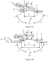
- FIG.7 An alternative embodiment is shown in Fig.7 in cross section, with the module 212 being indirectly linked with the mirror head cup 210 by means of a holding device 232. Adjusting elements 234 are provided as well by means of which the position of the module 212 relative to the mirror head cup 210 can be adjusted.
- Fig. 8 illustrates in top view the tilting of the projector module 212, guided via the link bracket 222.
- the maximum tilt angle in the illustrated example is approx. +/- 6° around a centre position of the module 212, limited by the stops of the elongated hole 226.
- the dashed outlines each show the end positions of the module 212.
- FIG. 9 shows an external view of a mirror head cup 210 which, on the one hand, carries an adjustable module 212 with its integrated projector or logo lamp 211 and an ambient or approach lamp 213 and, on the other hand, provides a window 236 for a manoeuvring light 238, shown in more detail in Fig. 11 .
- the additional manoeuvring light 338 projects light through the window 236, the emission area being determined by a plastic aperture 240.
- the latter comprises an opaque partial area 242, for example made from polycarbonate, and a transparent coloured partial area 244, for example made from polymethyl methyl acrylate coloured in blue.
- Fig. 10 shows the mirror head cup 210 of Fig. 9 , from the mirror head inside, with the module 212 with being fixed to the mirror head cup 210 by means of a holding device 232.
- the holding device 232 is attached to the mirror head cup 210 by means of clip connectors 246. Further clip connectors 248 fix the module 212 to the holding device 232.
- the link bracket 222 for adjusting the position of the projector module 212 can also be seen.
- the manoeuvring light 238 is shown as a module and in a mounted condition.
- the module comprises a circuit board 250 with lighting elements that emit light in the direction of the window 236 by means of fibre-optic light guides 252.
- the manoeuvring light 238 is included in a two-component housing 254 consisting of transparent acrylonitrile-butadiene-styrene-copolymer towards the window 236 and comprising cooling fins 256 made from aluminium for heat dissipation.
- An ambient lighting is possible by means of the manoeuvring light 238, in addition to the combined approach lamp and logo lamp module 12.
- a rear view assembly is thus created that enables an exact adjustment of the position of the module 212 so that this can provide a projection of a logo onto the road free from distortions.
- further lighting variants are connected with or even integrated in the module 212. This increases the application area in a minimum space.
Abstract
Description
- The present disclosure relates to an external rear view assembly with an adjustable module.
- An external rear view assembly for a motor vehicle comprises at least one reflective element such as a mirror, and/or a camera in cooperation with a display, with the display being arranged within the external rear view assembly attached at a side of the motor vehicle or within the motor vehicle. A conventional rear view side mirror or a camera pod are examples of rear view assemblies.
- A rear view assembly for a motor vehicle offers a view of the area behind the motor vehicle at least in compliance with the legal provisions and belongs to a sub-group of assemblies for an indirect view. These provide images and views of objects which are not in the driver's direct field of view, i.e., in directions opposite of, to the left of, to the right of, below and/or above the driver's viewing direction. The driver's view cannot be fully satisfactory, in particular also in the viewing direction; the view can, for example, be obstructed by parts of the driver's own vehicle, such as parts of the vehicle body, in particular, the A-pillar, the roof construction and/or the bonnet and the view may be obstructed by other vehicles and/or objects outside the vehicle that can obstruct the view to such an extent that the driver is not able to grasp a driving situation to his/her full satisfaction or only incompletely. It is also possible that the driver is not able to grasp the situation in or outside of his/her viewing direction in the way required to control the vehicle according to the situation. Therefore, a rear view assembly can also be designed in such a way that it processes the information according to the driver's abilities in order to enable him/her to grasp the situation in the best possible manner.
- Different functions and devices can be built into rear view assemblies and/or controlled with the help of rear view assemblies wherein cameras are included as well. The functions and devices for improving, enhancing, and/or maintaining the functionality of the rear view assembly under normal or extreme conditions are particularly useful. They can comprise heating or cooling systems, cleaning materials such as wipers, liquid and/or gaseous sprays, actuator means for moving the rear view assembly and parts thereof such as a display, a camera system and/or parts of a camera system, for example, comprising lenses, filters, light sources, adaptive optics such as formable mirrors and/or actuator means for the induction of movements of other objects, for instance, parts of the vehicle and/or objects surrounding the vehicle.
- Moreover, the rear view assembly can comprise linear guiding devices and/or rotating wheels, such as a filter wheel, for exchanging optical elements, for example, comprising lenses, mirrors, light sources, sensors, adaptive optics such as formable mirrors and/or filters.
- Further devices can be integrated in rear view assemblies and/or further devices can be controlled by means of rear view assemblies, such as any kind of light module comprising an external light module, an internal light module, a front light, a rear light, fog lights, a brake light, an accelerator light, a blinking light, a logo light, an apron lighting, a ground light, a puddle light, a flash light, a navigation light, a position light, an emergency light, headlights, a green light, a red light, a warning light, a blinking light module, an approach light, a search light, an information light, an indicator and/or the like. Further examples for functions and devices which can be integrated in or controlled by rear view assemblies can be a fatigue detection system, a system to detect momentary nodding off, a distance and/or speed determination system, for example, a LIDAR (light detection and ranging) system, a blind angle indication system, a lane-change assistance system, a navigation assistance system, a tracking assistance system, a man-machine interaction system, a machine-machine interaction system, an assistance system for emergency and precautionary measures, such as an accident prevention assistance system, a countermeasure assistance system, a braking assistance system, a steering assistance system, an accelerator assistance system, an escape assistance system which, for example, comprises a catapult seat system, a direction indicator, a blind angle indicator, an approach system, an emergency brake system, a charging status indicator, a vehicle mode system, for instance, comprising a sports-mode system, an economy-mode system, an autonomous driving-mode system, a sleep mode system and/or an anti-theft system, a vehicle-locked indication system, a vehicle-stolen indicator, a warning signal system, a temperature indicator system, a weather indication system, a traffic light signal system, a fuel status system and/or any combination thereof.
- Lighting devices for rear view assemblies and/or associated fibre-optic light guides are described in the
German patent application No. 102012108488 , in theGerman patent application No. 102012104529 , in theGerman patent application No. 102012107833 , in theGerman patent application No. 102012107834 , inEuropean patent No. 2738043 , inEuropean patent No. 2947378 , in the international patent application No.2015/173695 , in theEuropean patent application No. 3045944 , in theU.S. patent application No. 15 / 228,566 , in theU.S. patent application No. 15 / 000,733 , in the international patent application No.2016/147154 , in theU.S. patent application No. 15 / 256,532 , in theGerman patent application No. 102015115555 , in theEuropean patent application No. 3144183 , of the applicant. - A camera module can in particular comprise a multitude of different optical elements, inter alia, comprising a multitude of different sensors and light sources as well as housing parts. The housing of a camera module can be made of plastic, metal, glass, another suitable material and/or any combination thereof and can be used in combination with the techniques for changing or modifying the properties of the material or the material surface. Housings are, for example, disclosed in the
German patent application No. 102016108247.3 . - The camera can, for example, comprise CCD or CMOS or light field sensors as they are, for example, described in the
German patent application No. 102011053999 and inU.S. patent No. 6,703,925 . A certain sector of the sensor can also be reserved for different purposes, for instance, for detecting a test beam, as disclosed inU.S. patent No. 8,031,224 . - The optical elements can be formed or designed from any type of glass or any other suitable material. Here, glass is used in the sense of a non-crystalline amorphous solid body showing a glass transition when being heated towards the liquid state. It comprises, for example, the group of polymer glasses, metal glasses, silicon oxide glasses, but also any other suitable material can be used that shows the glass transition. The glass can be either plane, wedge-shaped, rectangular, cylindrical, spherical, conical, elliptical, and/or circular, as it is, for example, described in the
German patent application No. 102016108247.3 and theGerman patent application No. 102011103200 , or may be formed according to the different requirements or lens types. As non-limiting examples, camera modules can be equipped with lenses such as wide-angle or fisheye lenses, which are suited to provide peripheral pictures, as described in theU.S. patent application No. 15 / 281,780 and theU.S. patent application No. 13 / 090,127 , a Fresnel lens or micro lenses, as described in theGerman patent application No. 102011053999 , or a TIR (total intern reflection) lens, as described inU.S. patent No. 8,740,427 . Another type of optical elements which are notoriously used in camera modules, are optical fibres, in particular, in the form of fibre bundles and preferably in the form of fibre bundles with an optical head, such as described in theU.S. patent application No. 09 / 771,140 . Different processes can be applied in order to manufacture such optical elements, such as the process described inU.S. patent No. 8,460,060 . The optical elements can be transparent as, for instance, inUS patent No. 8,031,224 , in theGerman patent application No. 102016108247.3 and in theU.S. patent application No. 13 / 242,829 . However, the optical elements can be semi-transparent as well, as described in theU.S. patent application No. 09 / 771,140 and theU.S. patent application No. 13 / 090,127 . Furthermore, the optical elements can be completely or partly coated with different types of coatings in order to achieve different effects, such as anti-reflection coatings, seeU.S. patent No. 8,031,224 , reflection coatings on a chrome basis, seeU.S. patent No. 9,181,616 U.S. patent application No. 14 / 936,024 and in theU.S. patent application No. 15 / 124,310 . The optical elements preferably consist of a scratch-proof material, as, for example, described in theGerman patent application No. 102016108247.3 . - In certain spots of the optical elements, the optical elements can have decoupling structures, and an optical film, an extrusion film for example, and a formed coating can be applied, as described in the
German patent application No. 102011103200 . A coating for spectral and tension control is described in theU.S. patent application No. 15 / 124,310 . Different filters can be integrated in the optical elements, such as grey filters or polarisation filters, which are described in theU.S. patent application No. 14 / 809,509 . Electrochromic substrates, polymer electrolytes, and other charge-conductive media can be comprised for the optical elements on the basis of the descriptions, as disclosed in theEuropean patent application No. 08103179.1 European patent No. 2202826 , theU.S. patent No. 7,999,992 , and theU.S. patent No. 8,537,451 . - The camera module can also be equipped with devices for controlling the light intensity, as described, for example, in the
U.S. patent application No. 14 / 809,509 and comprise light level amplifier tubes, as described in theU.S. patent application No. 09 / 771,140 . The electrochromic substrates and apparatuses used in theEuropean patent application No. 08103179.1 European patent No 2202826 , theU.S. patent No. 7,999,992 , and theU.S. patent No. 8,537,451 can also be used for this purpose just like a transflector for transmitting or reflecting light on the basis of a respective input signal, as described in theGerman patent application No. 102016106126.3 . - The camera module or a cover adapted to the camera module can be moved by different actuators, drive units, and/or a flexible track, as described, for instance, in the
German patent application No. 102016108247.3 and theU.S. patent application No. 15 / 281,780 . Moreover, the camera module can also comprise cleaning elements in order to clean the outward pointing optical element exposed to the environment. The cleaning element can, for example, contain wipers, brushes, lips, nozzles, ventilators, and similar elements, as they are described in theEuropean patent application No. 14165197.6 U.S. patent application No. 15 / 281,780 , theGerman patent application No. 102016108247.3 , theEuropean patent application No. 13163677.1 European patent application No. 15173201.3 European patent No. 1673260 . The cleaning devices are not limited as to their composition and can, for example, comprise any kind of tissues, elastomers, sponges, brushes, or combinations thereof. Special wiper elements that comprise wiper arms, wiper blades, wiping cloths, wiping tissues, and combinations thereof are described in theEuropean patent application No. 14165197.6 European patent application No. 130164250.6 European patent application No. 14165197.6 - Different processes can be used in order to detect dirt or other blurs which impede or impair the functioning of the camera module, as described in the
U.S. patent No. 8,395,514 , theEuropean patent No. 1328141 , and theU.S. patent No. 8,031,224 . In addition, light sources can be built or integrated in the camera module in order to increase the visibility of surrounding objects, to measure distances and directions, and to detect dirt, as described in theU.S. patent No. 8,031,224 , theU.S. patent application No. 62 / 470,658 U.S. patent application No. 09 / 771,140 . - It is known to provide such cameras with heating devices and/or protection glasses. For this purpose, heating foils are, for instance, glued onto or laminated with the protection glass. The manufacturing of such a solution is costly and, due to the low thermal mass of such a heating foil, it has only a low heating capacity. Different heating means, such as heating coils, heating devices integrated in the lens mounting or lining or other heating elements can be used in order to prevent condensation and icing on the surface of optical elements, such as described in the
German patent application No. 102016108247.3 and theU.S. patent application No. 62 / 470,658 - Waterproof seals against weather conditions as well as against the influence of washing processes with cleaning agents, solvents, and high-pressure cleaners can be used for the housing of the camera module, as described, for example, in the
U.S. patent application No. 13 / 090,127 . Alternatively, the housing can be made in one piece, which consists of plastic and a conductive material, the conductive material being spread in the plastic material in order to form a conductive mass, enabling a power source, preferably a DC voltage source, to be connected with the body via at least two electrodes and to warm up the body accordingly. A conductive track can be embedded in the plastic parts of the camera module, as described in theEuropean patent No. 1328141 and theU.S. patent No. 7,083,311 . - The camera module can comprise an energy collection system, as, for example, described in the
European patent application No. 09171683.7 U.S. patent No. 8,487,633 , can be used in order to detect a failure of the camera module. - Different types of fixings can be used in order to attach the camera module to the vehicle or to other components, such as the snap-in connection described in
European patent No. 2233360 . - Different controlling means and analysis devices can be used, for example, the calculation units described in the
U.S. patent application No. 13 / 090,127 , theGerman patent application No. 102016106126.3 , theGerman patent application No. 102011053999 , theEuropean patent application No. 2146325 , and theU.S. patent No. 8,849,104 . In addition, the HDR (high dynamic range) technology according to theU.S. patent application No. 14 / 830,40 can be used. - Additional functional elements and/or decorative elements, such as logo projectors, are thus increasingly integrated in rear view assemblies of vehicles. By means of such a logo projector, a symbol, for example the manufacturer's logo, can be projected onto the road. For this purpose, the logo projector comprises a light source, a mask, and/or a slide for determining the logo as well as a projection lens. In order to make sure that the logo can be projected onto the road without any distortions, the position of the logo projector must be exactly defined. However, since, apart from the internal tolerance of the logo projector, i.e., the relative position between the mask and the lens, there are usually further tolerances, for example between the logo projector and the mirror housing, between the mirror head and the mirror foot, as well as between the mirror foot and the vehicle body, the position of the logo projector is not always exactly defined. This may result in undesired angular deviations and/or distortions of the projected logo.
- Some rear view side mirrors incorporate approach lamps (also known as puddle lamps) within the side mirror housing which are used to project light downward onto the ground adjacent a vehicle. Standard (or basic) approach lamps have a light source such as an LED that is directed through an aperture in the lower surface of the side mirror. The light source is held at a desired fixed distance from the aperture and may use simple optical arrangements such as a light pipe to direct light through the aperture. More recently more sophisticated projector based approach lamps have been developed that use a lens arrangement incorporating a filter, mask, or screen (or similar) to project a logo, image symbol, message, or the like (referred to as logo in the following) through the aperture. These will be referred to as logo lamps with logo elements to distinguish them from standard approach lamps. Projection of the logo requires the use more complicated optical arrangements compared with standard approach lamps, and thus such projector approach lamps are typically physically larger and more expensive than standard approach lamps.
- Still further, some mirrors incorporate both standard approach lamps and logo lamps. For example a standard approach lamp can be used to provide broad illumination for low speed maneuvering, whilst a logo lamp can be used to project a defined logo on the ground when stationery (eg when approaching or leaving the vehicle). One problem with providing both standard approach lamps and logo lamps is that the available space within a rear view side mirror for an approach lamp is typically quite limited, and the approach lamp modules must fit around or in spaces between the side mirror components such as mirrors and motors which creates design challenges. Further vehicles are requiring larger and larger illumination angles from approach lamps to both please the end user and allow camera systems to see around the car, which creates further design challenges in creating combined approach and logo lamp modules.
-
WO 2016/012651 A1 , describing a combined approach lamp and logo lamp apparatus for use in an external rear view assembly according to the pre-amble ofclaim 1 of the present disclosure, relates to a multifunctional assembly including an external surface structure that comprises a side door and is equipped with at least one external rear-view assembly and an external handle assembly for opening the door. It also includes an external laser emitter which emits a line of laser light line in a fixed and direct manner downwards onto the ground adjacent to the vehicle, indicating a door-opening area, and performs functions in a combined manner with other blinkers, sensors and control devices upon opening the door and with an ultraviolet light emitting device. - The object of the present disclosure is to provide an external rear view assembly to overcome the drawbacks of the prior art. This object is achieved by the features of
claim 1.Claims - Further, there is provided a combined approach lamp and logo lamp apparatus for use in an external rear view assembly comprising at least one aperture, the apparatus comprising: a housing comprising a rear face and a front face with the at least one aperture; a printed circuit board (PCB) mounted adjacent the rear face, the printed circuit board further comprising a power connector, an electronic circuit, a first light source mounted in a first location on the printed circuit board and a second light source mounted in a second location on the printed circuit board; and a transparent lens component comprising a first lens portion and a second lens portion, wherein the housing and the lens component are formed, preferably as a two component moulded part, such that the first lens potion is orientated to focus light from the first light source and the second lens portion is orientated to focus light from the second light source via an optical assembly comprising a logo element, and the first lens portion is angled relative to a plane containing the PCB surface so that the distance from the first light source to an outer surface of the first lens portion is less than the distance from the second light source to an outer surface of the second lens portion, with, in use, the housing being mounted so that the first lens portion and the second lens portion are adjacent the at least one aperture in the side mirror housing.
- The at least one aperture may comprise a first aperture and a second aperture separated by an opaque bridging portion; the first lens potion is located in the first aperture and the second lens portion is located in the second aperture; and the second lens portion is separated from the first lens portion by an joining portion, with the joining portion preferably being covered by the opaque bridging portion.
- The PCB may have an area of at least 750 mm2, preferably at least 900 mm2, more preferably at least 1100 mm2.
- The electronic circuit may be configured to separately control the output of the first light source and the output of the second light source, and the output of each light source is controlled to limit the total output under a predetermined maximum thermal dissipation limit. Both light sources can be actuated at the same time, with preferably a resettable fuse for an overheat control being provided. It is also proposed that the electronic circuit is configured to operate the combined approach lamp and logo lamp apparatus in at least two modes, wherein in each mode the total output remains under a predetermined maximum thermal dissipation limit, and in the first mode both the first light source and the second light source are switched on, and in the second mode only one of the first light source or second light source is switched on, and generates light with an intensity larger than an intensity of the same light source when operated in the first mode.
- The first lens portion may be angled with respect to the plane containing the PCB surface, with preferably the first lens portion being angled with respect to the plane containing the PCB surface with an angle in the range of 10° to 25°, more preferably 15° to 20°, and/or the first lens portion is of the light pipe type, preferably multi faceted.
- The second lens portion may be parallel to the plane containing the PCB surface and/or recessed.
- The first light source may be comprised of an approach lamp; wherein the first lens portion has a first width and is mounted in a first offset position at an offset distance from the outer surface of the lower surface of the side mirror housing; and the approach lamp aperture has a second width which is wider than the first width of the first lens portion, with preferably the approach lamp projecting light both forward and rearward, in particular at a forward angle between 50° and 65° and a rearward angle between 50° and 75°.
- The rear surface supports the PCB with the power connector, which preferably comprises two prongs which engage with a plug which operatively connects the prongs to cables through a seal.
- Further there may be a power connector housing, in particular in a proximal face, provided by the housing, which preferably is opaque and further comprises a first side face, a second side face, and a distal face, the proximal face comprising an aperture for receiving at least one cable.
- Still further, there may be a mounting flange for mounting the combined approach lamp and logo lamp apparatus to an interior housing of the rear view side mirror through a mirror aperture, with the mounting flange preferably being located on either the first side face or the second side face, and the rear surface engages with the housing to form a rear face and the rear surface; and/or further comprising connection means, in particular for a screw, snap and/or clip connection, for mounting the combined approach lamp and logo lamp apparatus to the external rear view assembly, preferably via a mirror adaptor.
- Still further, an adjusting device for spatially adjusting the apparatus relative to a housing part of the rear view assembly may be used, in particular relative to a housing cap and/or a foot cover, wherein the adjusting device preferably comprises at least one first adjusting element being arranged at the apparatus or formed together with an apparatus housing and/or provides at least one translational degree of freedom along at least one shifting axis and/or at least one rotational degree of freedom around at least one rotational axis.
- The external rear view assembly may comprise the combined approach lamp and logo lamp apparatus. This external rear view assembly may comprise at least one second adjusting element of the adjusting device that is arranged at or formed together with a holding device for the apparatus and/or the housing part, and/or the adjusting device comprises at least one fixing element for fixing the apparatus in a position adjusted by means of the adjusting device, preferably via at least one fixing screw and/or bonding.
- Embodiments of the present disclosure will be discussed with reference to the schematic accompanying drawings wherein:
- Figure 1A
- is a isometric view of the interior of a rear view side mirror comprising a combined approach lamp and logo lamp;
- Figure 1B
- is a isometric view showing the underside of the rear view side mirror shown in
Figure 1A ; - Figure 2A
- is a first isometric view of a combined approach lamp and logo lamp;
- Figure 2B
- is a second isometric view of the combined approach lamp and logo lamp of
Figure 2A ; - Figure 2C
- is an isometric view of the combined approach lamp and logo lamp of
Figure 2B with the housing hidden; - Figure 3
- is an exploded isometric view of the combined approach lamp and logo lamp of
Figure 2A ; - Figure 4A
- is a front view of the combined approach lamp and logo lamp of
Figure 2A ; - Figure 4B
- is a rear view of the combined approach lamp and logo lamp of
Figure 2A ; - Figure 4C
- is a first side view of the combined approach lamp and logo lamp of
Figure 2A ; - Figure 4D
- is a second side view of the combined approach lamp and logo lamp of
Figure 2A ; - Figure 4E
- is a top view of the combined approach lamp and logo lamp of
Figure 2A ; - Figure 4F
- is a bottom view of the combined approach lamp and logo lamp of
Figure 2A ; - Figure 4G
- is a sectional view of section AA of
Figure 4A ; - Figure 5A
- is a side sectional view of the combined approach lamp and logo lamp of
Figure 2A mounted above the lower surface of a mirror housing in a first offset position according to an embodiment; - Figure 5B
- is a side sectional view of a combined approach lamp and logo lamp with the approach lamp lens portion mounted parallel to the PCB board;
- Fig. 6
- is a perspective view of a mirror housing part with a first adjustable module for a combined approach lamp and logo lamp, from the inside, in line with the present invention;
- Fig. 7
- is a partial sectional view of a mirror housing part with a second adjustable module for a combined approach lamp and logo lamp;
- Fig. 8
- is a top view of a third adjustable module for a combined approach lamp and logo lamp, in different adjustment positions;
- Fig. 9
- is a perspective view of a mirror housing part with a fourth adjustable module for a combined approach lamp and logo lamp module from the outside;
- Fig. 10
- is a detailed view of the mirror housing part according to
Fig. 9 with a mounted, adjustable module, from the inside; and - Fig. 11
- is a detailed view of the mirror housing part according to
Fig. 9 with an additionally mounted manoeuvring light module, from the inside. - In the following description, like reference characters designate like or corresponding parts throughout the figures.
- Referring now to
Figure 1A , there is shown an isometric view of the interior of aninterior housing 106 of an external rear view assembly in form of a rearview side mirror 100 through themirror aperture 105. The mirror and mirror support and actuators have been omitted from this view to show the location of an embodiment of a combined approach lamp andlogo lamp 1 within theinterior housing 106. The combined approach lamp andlogo lamp 1 comprises a mounting plate orflange 19 on one side to mount the combined approach lamp andlogo lamp 1 to theinterior housing 106. Theinterior housing 106 further comprises a mountingaperture 107 for mounting the mirror to a vehicle, and provides an aperture through which power andcommand cables 39 can be provided to the approach lamp andlogo lamp 1 and other components located within the interior of theside mirror 100. -
Figure 1B is an isometric view showing theunderside surface 102 of theexterior housing 101 of the rearview side mirror 100 shown inFigure 1A . Theunderside surface 102 comprises anapproach lamp aperture 111 for projecting abroad spot beam 121 of light on the ground from the approach lamp 11 (in the combined approach lamp and logo lamp 1). Theunderside surface 102 also comprises alogo lamp aperture 112 for projecting alogo 122 of light on the ground from the logo lamp 12 (in the combined approach lamp and logo lamp 1). Additional apertures may be provided in theunderside surface 102 for projecting other beams, including both visible and invisible (eg IR) beams for sensing or illumination. - The size and shape of the projected
spot beam 121 is determined by the optics of the approach lamp lens as well as the offset distance of the lens from theapproach lamp aperture 111. Similarly the size and shape of the projectedlogo 122 is determined by the optics of the logo lamp lens as well as the offset distance of the lens from thelogo lamp aperture 112. The approach lamp beam and logo may be projected forward and/or rearward of the side mirror and may be local to the side door, or it may extend along the full length of the vehicle. The approachlamp spot beam 121 may be used for general ground illumination for example to provide broad illumination for camera systems during low speed manoeuvring, whilst the logo lamp may be used to provide light to passengers when entering or exiting the vehicle. In other embodiments the approachlamp spot beam 121 can be used for passenger illumination, while a separate lamp can be used for manoeuvring. Theapproach lamp 11 andlogo lamp 12 are spatially separated from each other within the combined approach lamp andlogo lamp 1 and thus theapproach lamp aperture 111 andlogo lamp aperture 112 may be separate apertures in theunderside surface 102. In another embodiment theapproach lamp aperture 111 and thelogo lamp aperture 112 are the same aperture which is an elongated aperture in which theapproach lamp projection 123 projects out of a different portion of the aperture to the logo lamp projection 124. That is both theapproach lamp 11 andlogo lamp 12 utilise the same exit (or projection) aperture in theunderside surface 102. In most embodiments the approach lamp and logo lamp are recessed from the lower surface to meet regulatory requirements. However in some alternative embodiments, the approach lamp and logo lamp could be configured to be flush with theunderside surface 102. - An embodiment of the combined approach lamp and
logo lamp 1 is shown in greater detail inFigures 2A though 4G.Figures 2A and 2B show a first and second isometric view of an embodiment of a combined approach lamp andlogo lamp 1.Figure 2C shows a similar view toFigure 2B with the housing hidden (or removed) to show the arrangement of internal components including thelens component 4 andFigure 3 is an exploded isometric view.Figures 4A, 4B, 4C 4D, 4E, and 4F are front, rear, first side, second side, top and bottom views.Figure 4G is a sectional view through section AA ofFigure 4A . - The combined approach lamp and
logo lamp 1 comprises anopaque housing 2 with afront face 13, afirst side face 15, asecond side face 16, a top ordistal face 17, and a bottom orproximal face 18. Arear surface 3 engages with the housing to form arear face 14. Thefront face 13 comprises a first aperture for theapproach lamp 11 and a second aperture for thelogo lamp 12 which are separated by anopaque bridging portion 45. When installed in a side mirror thefront face 13 faces the inner surface of theunderside surface 102. The location of thepower connector housing 40 can act as a reference point such that thebottom face 18 is a proximal face with respect to location of the power connector and thus thetop face 17 is the distal face. The mounting plate orflange 19 is located on thesecond side face 16 and is also proximal to the power connector 40 (and bottom or proximal face 18). Additionally thetop face 17 comprises a pair of mounting fingers which abut a support in the interior of the mirror housing (not shown). - A printed circuit board (PCB) 24 is mounted on or adjacent the
rear surface 3 and comprises apower connector 26, anelectronic circuit 25 and afirst light source 21 mounted in a first location on the printed circuit board, and a secondlight source 22 mounted in a second location on the printed circuit board. In this embodiment the first and second light sources are both LED light sources, but other light sources including laser or incandescent light sources could be used. The first light source is the light source for theapproach lamp 11 and the second light sources is for thelogo lamp 12. As can be seen inFigure 3 , the two light sources are spaced apart on the PCB. - The light sources are controlled via the
electronic circuit 25 which receives power and control signals via wires of thecables 39 operatively connector topower connector 26. Thepower connector 26 comprises two prongs which engage with aplug 37 which operatively connects the prongs towires 39 throughseal 38. Theseal 38 is inserted intopower connector housing 40 in theproximal face 18. Theelectronic circuit 25 may comprise a single circuit which can concurrently control each light source, for example to switch one or both light sources on or off via control signals sent on asingle wire 39, or the electronic circuit may comprise two separate circuits, one for each light source allowing individual and independent control of the lamps via signals sent on twoseparate wires 39. In one embodiment the LEDs have ratings in the range 0.5-1.5Watts each. The LED's may have the same ratings or different ratings. The use of two light sources generates heat, and to ensure adequate thermal dissipation of heat generated from the light sources, the PCB has a total area (or projected area) of at least 750mm2. Preferably the PCB has a total (or projected) area of at least 900mm2. The size of the PCB effectively sets the size of the rear surface. - The
electronic circuit 25 may also allow adjustment of the relative light output, for example over a range from 0 - 100 %. This adjustment may be performed individually for both light sources, or jointly. In some embodiments, the electronic circuit is configured to separately control the output of thelight sources 21 22, and the output of each light source is controlled to limit the total output under a predetermined maximum thermal dissipation limit (or capability) hmax . Individual control of the light output (or intensity) is used to provide different lighting levels for different functions. For example for cases where the user is approaching the vehicle the logo and approach lamp may both be illuminated at similar intensities such 50% of a maximum intensity (or up to ). However when manoeuvring with a camera the logo lamp may be turned off, and the approach lamp portion may be activated at a higher brightness (100%) in order to provide better vision or illumination for the camera. This higher brightness will generate additional heat (compared to the 50% brightness case) and thus this higher intensity can only be used when the logo lamp is not switched on otherwise the heat dissipation limit may be exceeded. In other modes, the lamps have different intensities (eg 25% logo, 75% approach), in which case the output of each light source is controlled to limit the total output under a predetermined maximum thermal dissipation limit (or capability) hmax . For example if the lamps are identical and generate heat at the same rate for the same input current, then we can define imax as the total current corresponding to the maximum thermal dissipation capability (hmax ) and i1 and i2 are the approach lamp and logo lamp currents. Then the lamps are operated such that the sum of the individual lamp currents satisfy: i 1 + i 2 ≤ imax. This can be rearranged to i 1/imax + i 2/imax ≤ 1, so that maximum intensity corresponds to imax and the intensity is relative to this value. That is the light intensities are controlled to 0-100% of imax (more generally the current symbols i could be replaced with intensity or brightness measurements I). More generally if the ratings of the lamps are different, or generate heat at different rates then we have f 1 + f 2 ≤ hmax where functions f1 and f2 are functions mapping an input parameter (eg current, voltage, etc) to heat output for each lamp. These may be obtained from fitting a function or creating a look up table from experimental test data and/or the theoretical estimates. The electronic circuit is then configured to ensure that in each mode the total heat output from both lamps stays within the acceptable limit hmax . For example the relationship between brightness or intensity and input current may be non-linear (or it may deviate from linear at larger currents). In further embodiments one or more temperature sensors are included in the electronic circuit, and the temperature is used in either the heat output estimates (ie inputs to f1 and f2 ) or to set the maximum heat dissipation limit. For example the maximum heat dissipation limit may depend upon (or vary with) the ambient temperature. As outlined above, the electronic circuit can be configured with a range of operational modes such that in each mode the total output remains under a predetermined maximum thermal dissipation limit. For example in the first mode both thefirst light source 21 and the secondlight source 22 are switched on with the same intensity, for example both at 50% of maximum intensity (or both at some level less < 50%). In a second mode only one of thefirst light source 21 or secondlight source 22 is switched on (for example approach lamp light source 21), and generates light with an intensity larger than an intensity of the same light source when operated in the first mode (eg > 50% of maximum intensity). - The combined approach lamp and
logo lamp 1 comprises atransparent lens component 4 which comprises afirst lens portion 41 and asecond lens portion 42 separated from the first lens portion by an joiningportion 43. Thefirst lens potion 41 is located in the first aperture of the front face of the housing, and orientated to focus light from thefirst light source 21. Similarly thesecond lens portion 42 is located in the second aperture and orientated to focus light from the secondlight source 22 via an optical assembly comprising a logo element, and the joiningportion 43 is covered by theopaque bridging portion 45 to prevent stray light from one lens/ lamp affecting the other lens/lamp. Additionally asupport area 46 surrounding the lens is opaque to further reduce stray light emissions. That is whilst the first lens portion and second lens portions are joined, there is no overlap in light output through thelens component 4 so that the approach lamp and logo lamp project through different areas of the onelens component 4. - The
opaque housing 2 andtransparent lens component 4 are formed as a two component injection moulded part. Aninjection moulding plug 44 is located below joiningportion 43. This allows bothlens portions lens component 4 to be formed as a single transparent (or translucent) part and the housing to formed as an opaque part so that an opaquelens bridging portion 45 can be provided to both separate the twolens portions support area 46 is also opaque further assisting in reducing stray light emissions. - The
first lens portion 41 is angled relative to a plane containing thePCB surface 24 so that thedistance 51 from thefirst light source 21 to an outer surface of thefirst lens portion 41 is less than thedistance 52 from the secondlight source 22 to an outer surface of thesecond lens portion 42. As shown inFigures 1A and 1B , andFigure 5A , when the housing is mounted in theside mirror housing 101, the combined approach lamp andlogo lamp housing 2 is mounted so that thefirst lens portion 41 and thesecond lens portion 42 are adjacent theapproach lamp aperture 103 and logo lamp aperture 104 respectively (or adjacent a single aperture if a single common aperture is provided in the side mirror housing). In this embodimentfirst lens portion 41 is angled with respect to the plane containing thePCB surface 24 andsecond lens portion 42 is parallel to the plane containing thePCB surface 24. In this embodiment thefirst lens portion 41 is angled with respect to the plane containing thePCB surface 24 with an angle of around 15°. In other embodiments the angle is in the range of 0° to 30° and more preferably in the range of 15° to 20° to maximise approach lamp efficiency and to fit to the side mirror. Angling of thefirst lens portion 41 improves the fit of the combined approach lamp andlogo lamp 1 to theside mirror housing 101. - The
first light source 21 andfirst lens portion 41 form theapproach lamp 11. The first lens portion is formed as a semi-circular Fresnel lens to form a wide spot beam capable of projecting light forward and rearward of the lens at angles as large as 75° to the vertical. In other embodiments the lens could be a freeform or total internal reflection lens, in particular in form of a light pipe. The secondlight source 22, optical assembly andsecond lens portion 42 form thelogo lamp 12. The optical assembly comprises afirst spacer housing 29, alogo plate 30 and asecond spacer housing 34. Thefirst spacer housing 29 comprises a pair ofprojections 28 which locate intomatching mounting apertures 27 in thePCB 24. Thefirst spacer housing 29 comprises a firstlogo lamp lens 23 which is located above second light source 22 (or aligned to collect light from second light source 22), and logoplate mounting projections 31. Thelogo plate 30 comprises logoplate mounting apertures 33 which receive the logoplate mounting projections 31, and alogo element 32 which receives light from the firstlogo lamp lens 23. Thesecond spacer housing 34 comprises a secondlogo lamp lens 35 which directs light passing through thelogo element 32 towards thesecond lens portion 42. Thesecond spacer housing 34 further comprisesspacer projections 36 to support thesecond lens portion 42 as shown inFigure 2C . Thefirst spacer housing 29 andsecond spacer housing 34 are formed as moulded pieces with the logo lamp lenses and mounting features moulded in the same piece. - As shown in
Figure 1A thevehicle side mirror 100 comprises aside mirror housing 101 with a lower surface 102 (that is when installed thelower surface 102 is proximal to the ground). The combined approach lamp andlogo lamp 1 is mounted within thehousing 101 such that thelens component 4 is mounted such thefirst lens portion 41 is parallel to thelower surface 102 and the first lens portion projects light through anapproach lamp aperture 103 in thelower surface 102. This is further illustrated inFigure 5A which is a side sectional view of the combined approach lamp and logo lamp ofFigure 2A mounted above thelower surface 102 of amirror housing 101. Thefirst lens portion 41 has afirst width 50, and is mounted in a first offset position at an offsetdistance 51 from the outer surface of thelower surface 102 of the side mirror housing. Theapproach lamp aperture 103 has asecond width 55 which is wider than thefirst width 50 of thefirst lens portion 41. In this embodiment the approach lamp projects light both forward and rearward at aforward angle 53 and arearward angle 54. Vehicles are requiring larger illumination angles to both please the end user and allow camera systems to see around the car. For example in the case of a 5 m long vehicle with the side mirror 2m from the front and 1m from the ground, then the requiredforward angle 53 is 63° and the requiredrearward angle 54 is 72°. - As will be shown below, the use of an angled
approach lamp lens 41 compared to an approach lamp lens parallel to the PCB surface can dramatically affect the required width of theapproach lamp aperture 103. A shown inFigure 5A , an angledapproach lamp lens 41 is used. In the case that thefirst width 50 of the first lens portion is 7mm, and located at a first offsetdistance 51 of 3mm then the requiredsecond width 55 of theapproach lamp aperture 103 is 22mm.Figure 5B shows a similar arrangement with an approach lamp lens 41' with the samefirst width 50 of 7mm, but aligned to be parallel with the PCB surface. This effectively recesses the approach lamp lens 41' with respect to the lower surface 102' and this has a dramatic effect on the size of the aperture 103' in the lower surface 102'. In the scenario shown inFigure 5B the combined approach and logo lamp uses an approach lamp lens (first lens potion 41) which is parallel to the PCB and thelower surface 102. Due to the size of the optical assembly of the logo lamp this forces and increase in the offset distance between the lower surface 102' and the first lens portion 41' by 5mm - from a second offsetdistance 51 of 3mm inFigure 5A to a second offset distance 51' of 8mm inFigure 5B . This has a dramatic effect on the required width of the approach lamp aperture 103', as to maintain the require opening angles 53 and 54, the second width 55' must be increased to 47mm - an increase of 25mm which is more than double the size of thesecond width 55 inFigure 5A . For reference the location of thelower surface 102, initial offsetdistance 51 andinitial width 55 shown inFigure 5A , all with respect to thefirst lens surface 41, are shown inFigure 5B as dotted lines. - This is undesirable as using a larger opening can compromise styling or induce wind noise. Alternatively if a large recess (offset distance) is used with a small aperture then this reduces the range of illumination angles thus reducing performance (ie less of the car is illuminated). These effects are particularly important when the combined approach and logo lamp is used in small mounting locations, such as in a camera pod rather than a side mirror, or in a small side mirror. Thus the use of an angled approach
lamp lens portion 41, rather than a lens parallel to the PCB provides the advantage of enabling small openings in the lower surface of the side mirror housing (or similar housing). - The above embodiments have been described in relation to mounting in a side mirror housing. In one embodiment a side mirror apparatus is provided comprising a housing comprising a lower surface which in use is proximal to the ground, and the lower surface comprises at least one
aperture 103, and a combined approach lamp and logo lamp apparatus mounted within the housing such thatPCB 24 is angled with respect to thelower surface 102 and thefirst lens portion 41 is parallel to thelower surface 102 and projects light through one of the at least oneaperture 103. However the combined logo and approach lamp could be provided in other similar vehicle structures such as a camera pod or sensing pod mounted on the exterior of a vehicle (whether on the side, front, rear, or other location). - Other variations are possible. In the above embodiment the
housing 2 forming part of the two component injection moulded part comprises thefront face 13, thefirst side face 15, the asecond side face 16, thetop face 17, and thebottom face 18, which engages with a separate rear surface, and the entire housing is opaque. In one embodiment thehousing 2 andlens component 4 are a multi component injection moulded part, such thatlens component 4 is a transparent part, thefront face 13 of the housing is one part and is opaque, and the remaining part of the housing is at least another part which is not necessarily opaque. In another embodiment thePCB 24 forms therear surface 3. In another embodiment the housing forming part of the two component moulded part comprises just thefront face 13 with apertures for the first and second lens portions (ie the approach and logo lamp lens of the lens component 4). This housing could be received on second housing comprising thefirst side face 15, thesecond side face 16, thetop face 17, thebottom face 18 and therear face 13. - The combined approach lamp and logo lamp apparatus has a number of advantages. First the use of a two component moulded opaque housing and transparent lens component provides improved separation of the two light exiting faces (the approach
lamp lens portion 41 and logo lamp lens portion 42) whilst maintaining a low part count. The two component moulded part allows both lens to be formed as a single transparent (or translucent) part and the housing to formed as an opaque part so that an opaquelens bridging portion 45 can be provided to both separate the twolens portions support area 46 is also opaque further assisting in reducing stray light emissions. Further the PCB is sized for adequate thermal management, and angling theapproach lamp lens 41 with respect to thePCB 24 plane allows the approach lamp lens to be parallel with an opening in the side mirror housing, which minimises the size of the opening (ie enables a small opening) in the lower surface of the side mirror housing. This also allows for a better fit of the combined approach lamp and logo lamp to the mirror housing. - A rear view assembly according to the invention can have a mirror head movably attached to a mirror foot (not shown) and an
adjustable module 212 for a combined approach lamp and logo lamp surface, with themodule 212 being attached to an inner surface of a mirror housing part in form of amirror head cup 210, as shown inFig. 6 . Themirror head cup 210, when mounted to a vehicle (not shown), is forward facing in the direction of the vehicle's longitudinal axis. Components such as themodule 212 are mounted to themirror head cup 210 either directly or indirectly linked with it by means of holding elements. In the example shown inFig. 6 , the mounting is directly made at themirror head cup 210. - In order to be able to correct tolerance-related position deviations of the
module 212, an adjustingscrew 214 is provided which is inserted in ascrew boss 216 of themirror head cup 212. Snap-inelements 218 are provided at the adjustingscrew 214 which engage with complementary snap-inelements 220 of themodule 212. - By turning the adjusting
screw 214, themodule 212 can be tilted so that its position relative to themirror head cup 210 can be corrected. In this process, the movement of themodule 212 is controlled by means of alink bracket 222 which is formed at ahousing 224 of themodule 212 and comprises a bentelongated hole 226. A fixingscrew 228 being inserted in ascrew boss 230 of themirror head cup 210 is led through theelongated hole 226. As soon as themodule 212 is moved to its target position by turning the fixingscrew 214, it can be fixed in this position by tightening the fixingscrew 228. - An alternative embodiment is shown in
Fig.7 in cross section, with themodule 212 being indirectly linked with themirror head cup 210 by means of aholding device 232. Adjustingelements 234 are provided as well by means of which the position of themodule 212 relative to themirror head cup 210 can be adjusted. -
Fig. 8 illustrates in top view the tilting of theprojector module 212, guided via thelink bracket 222. The maximum tilt angle in the illustrated example is approx. +/- 6° around a centre position of themodule 212, limited by the stops of theelongated hole 226. The dashed outlines each show the end positions of themodule 212. - A further embodiment of a rear view assembly is shown in
Figures 9 through 11 .Fig. 9 shows an external view of amirror head cup 210 which, on the one hand, carries anadjustable module 212 with its integrated projector orlogo lamp 211 and an ambient orapproach lamp 213 and, on the other hand, provides awindow 236 for amanoeuvring light 238, shown in more detail inFig. 11 . The additional manoeuvring light 338 projects light through thewindow 236, the emission area being determined by aplastic aperture 240. The latter comprises an opaquepartial area 242, for example made from polycarbonate, and a transparent colouredpartial area 244, for example made from polymethyl methyl acrylate coloured in blue. -
Fig. 10 shows themirror head cup 210 ofFig. 9 , from the mirror head inside, with themodule 212 with being fixed to themirror head cup 210 by means of aholding device 232. The holdingdevice 232, in turn, is attached to themirror head cup 210 by means ofclip connectors 246.Further clip connectors 248 fix themodule 212 to theholding device 232. Thelink bracket 222 for adjusting the position of theprojector module 212 can also be seen. - In the illustration in
Fig.11 themanoeuvring light 238 is shown as a module and in a mounted condition. The module comprises acircuit board 250 with lighting elements that emit light in the direction of thewindow 236 by means of fibre-optic light guides 252. Themanoeuvring light 238 is included in a two-component housing 254 consisting of transparent acrylonitrile-butadiene-styrene-copolymer towards thewindow 236 and comprising coolingfins 256 made from aluminium for heat dissipation. An ambient lighting is possible by means of themanoeuvring light 238, in addition to the combined approach lamp andlogo lamp module 12. - All in all, a rear view assembly is thus created that enables an exact adjustment of the position of the
module 212 so that this can provide a projection of a logo onto the road free from distortions. At the same time, further lighting variants are connected with or even integrated in themodule 212. This increases the application area in a minimum space. - Throughout the specification and the claims that follow, unless the context requires otherwise, the words "comprise" and "include" and variations such as "comprising" and "including" will be understood to imply the inclusion of a stated integer or group of integers, but not the exclusion of any other integer or group of integers.
- The reference to any prior art in this specification is not, and should not be taken as, an acknowledgement of any form of suggestion that such prior art forms part of the common general knowledge.
- It will be appreciated by those skilled in the art that the disclosure is not restricted in its use to the particular application or applications described. Neither is the present disclosure restricted in its preferred embodiment with regard to the particular elements and/or features described or depicted herein. It will be appreciated that the disclosure is not limited to the embodiment or embodiments disclosed, but is capable of numerous rearrangements, modifications and substitutions without departing from the scope as set forth and defined by the following claims.
- Please note that the following claims are provisional claims only, and are provided as examples of possible claims and are not intended to limit the scope of what may be claimed in any future patent applications based on the present application. Integers may be added to or omitted from the example claims at a later date so as to further define or re-define the scope.
-
- 1
- combined approach lamp and logo lamp
- 2
- opaque housing
- 3
- rear surface
- 4
- transparent lens component
- 11
- approach lamp
- 12
- logo lamp
- 13
- front face
- 15
- first side face
- 16
- second side face
- 17
- top or distal face
- 18
- bottom or proximal face
- 19
- mounting plate or flange
- 21
- first light source
- 22
- second light source
- 23
- first logo lamp lens
- 24
- printed circuit board
- 25
- electronic circuit
- 26
- power connector
- 27
- mounting apertures
- 28
- pair of projections
- 29
- first spacer housing
- 30
- logo plate
- 31
- logo plate mounting projections
- 32
- logo element
- 33
- logo plate mounting apertures
- 34
- second spacer housing
- 35
- second logo lamp lens
- 36
- spacer projections
- 37
- plug
- 38
- seal
- 39
- power and command cables
- 40
- power connector housing
- 41, 41'
- first lens portion
- 42
- second lens portion
- 43
- joining portion
- 44
- injection moulding plug
- 45
- opaque bridging portion
- 46
- support area
- 50
- first width
- 51, 51'
- distance
- 52, 52'
- distance
- 53
- forward angle
- 54
- rearward angle
- 55, 55'
- second width
- 100
- rear view side mirror
- 101
- exterior housing
- 102, 102'
- underside or lower surface
- 103, 103'
- approach lamp aperture
- 104
- logo lamp aperture
- 105
- mirror aperture
- 106
- interior housing
- 107
- mounting aperture
- 111
- approach lamp aperture
- 112
- logo lamp aperture
- 121
- spot beam
- 122
- logo
- 123
- approach lamp projection
- 124
- logo lamp projection
- 210
- mirror head cup
- 211
- projector or logo lamp
- 212
- combined approach lamp and logo lamp module
- 213
- ambient or a approach lamp
- 214
- adjusting screw
- 216
- screw boss
- 218
- snap-in element
- 220
- snap-in element
- 222
- link bracket
- 224
- housing
- 226
- elongated hole
- 228
- fixing screw
- 230
- screw boss
- 232
- holding device
- 234
- adjusting element
- 236
- window
- 238
- manoeuvring light
- 240
- plastic aperture
- 242
- opaque partial area
- 244
- transparent coloured partial area
- 246
- clip connector
- 248
- clip connector
- 250
- circuit board
- 252
- fibre-optic light guide
- 254
- housing
- 256
- cooling fins
Claims (4)
- An external rear view assembly (100), having a mirror head movably attached to a mirror foot and an adjustable module (212), with the module (212) being attached to an inner surface of a mirror housing part in form of a mirror head cup (210), wherein,in order to be able to correct tolerance-related position deviations of the module (212), an adjusting screw (214) is provided which is inserted in a screw boss (216) of the mirror head cup (210), snap-in elements (218) are provided at the adjusting screw (214) which engage with complementary snap-in elements (220) of the module (212); and
by turning the adjusting screw (214) , the module (212) can be tilted so that its position relative to the mirror head cup (210) can be corrected, wherein the movement of the module (212) is controlled by means of a link bracket (222) which is formed at a housing (224) of the module (212) and comprises a bent elongated hole (226). - The external rear view assembly (100) according to claim 1, wherein
a fixing screw (228) is inserted in a screw boss (230) of the mirror head cup (210) and is led through the elongated hole (226), such that as soon as the module (212) is moved to its target position by turning the adjusting screw (214), it can be fixed in this position by tightening the fixing screw (228). - The external rear view assembly (100) according to claim 1 or 2, wherein
the module (212) is suited for a combined approach lamp and logo lamp. - A motor vehicle with an external rear view assembly (100) as claimed in any one of the preceding claims.
Applications Claiming Priority (4)
| Application Number | Priority Date | Filing Date | Title |
|---|---|---|---|
| AU2017901442A AU2017901442A0 (en) | 2017-04-20 | Combined approach lamp and logo lamp | |
| DE102017130246.8A DE102017130246A1 (en) | 2017-12-15 | 2017-12-15 | Lighting device, rear view device and motor vehicle |
| PCT/EP2018/059959 WO2018193000A1 (en) | 2017-04-20 | 2018-04-18 | Combined approach lamp and logo lamp |
| EP18721970.4A EP3612413B1 (en) | 2017-04-20 | 2018-04-18 | Combined approach lamp and logo lamp |
Related Parent Applications (2)
| Application Number | Title | Priority Date | Filing Date |
|---|---|---|---|
| EP18721970.4A Division-Into EP3612413B1 (en) | 2017-04-20 | 2018-04-18 | Combined approach lamp and logo lamp |
| EP18721970.4A Division EP3612413B1 (en) | 2017-04-20 | 2018-04-18 | Combined approach lamp and logo lamp |
Publications (2)
| Publication Number | Publication Date |
|---|---|
| EP4234333A2 true EP4234333A2 (en) | 2023-08-30 |
| EP4234333A3 EP4234333A3 (en) | 2023-11-08 |
Family
ID=62111026
Family Applications (2)
| Application Number | Title | Priority Date | Filing Date |
|---|---|---|---|
| EP23179214.4A Pending EP4234333A3 (en) | 2017-04-20 | 2018-04-18 | Combined approach lamp and logo lamp |
| EP18721970.4A Active EP3612413B1 (en) | 2017-04-20 | 2018-04-18 | Combined approach lamp and logo lamp |
Family Applications After (1)
| Application Number | Title | Priority Date | Filing Date |
|---|---|---|---|
| EP18721970.4A Active EP3612413B1 (en) | 2017-04-20 | 2018-04-18 | Combined approach lamp and logo lamp |
Country Status (4)
| Country | Link |
|---|---|
| US (2) | US10967799B2 (en) |
| EP (2) | EP4234333A3 (en) |
| CN (2) | CN111094066B (en) |
| WO (1) | WO2018193000A1 (en) |
Families Citing this family (13)
| Publication number | Priority date | Publication date | Assignee | Title |
|---|---|---|---|---|
| CN111197729A (en) * | 2019-06-04 | 2020-05-26 | 深圳市新缔科技有限公司 | Automobile welcome lamp |
| CN110764269B (en) * | 2019-11-02 | 2021-06-01 | 深圳市麓邦技术有限公司 | Optical gradual change system and method |
| TWI764063B (en) * | 2019-11-13 | 2022-05-11 | 揚明光學股份有限公司 | Puddle lamp |
| FR3105345B1 (en) | 2019-12-20 | 2022-10-14 | Valeo Vision Belgique | Automotive lighting device |
| US10946815B1 (en) * | 2020-03-02 | 2021-03-16 | Ford Global Technologies, Llc | Vehicle badge assembly |
| DE102020108009A1 (en) * | 2020-03-24 | 2021-09-30 | Bayerische Motoren Werke Aktiengesellschaft | Motor vehicle |
| KR20210153902A (en) * | 2020-06-11 | 2021-12-20 | 현대모비스 주식회사 | Camera-Puddle Lamp Integrated Apparatus and Side Mirror Including the Same |
| DE102020216041A1 (en) | 2020-12-16 | 2022-06-23 | OSRAM CONTINENTAL GmbH | OPTICAL ELEMENT, PROJECTION MODULE, VEHICLE AND PROCESS |
| DE102021107473B3 (en) * | 2021-03-25 | 2022-08-04 | Motherson Innovations Company Limited | LIGHT MODULE AND EXTERIOR REAR VIEW DEVICE |
| US20230060185A1 (en) * | 2021-08-24 | 2023-03-02 | Lumileds Llc | Led retrofit vehicle signaling lamp with projection led light source, smartphone app for controlling it and corresponding system |
| DE102021126343A1 (en) | 2021-10-12 | 2023-04-13 | Ford Global Technologies, Llc | Lighting device for light projection of a pattern, vehicle exterior mirror and vehicle |
| EP4253150B1 (en) | 2022-03-29 | 2024-05-01 | Motherson Innovations Company Limited | Hybrid semi-dynamic animated logo lamp, vehicle component and vehicle |
| EP4253149A1 (en) * | 2022-03-31 | 2023-10-04 | Motherson Innovations Company Limited | Logo lamp device, rear view system, vehicle and method for assembling |
Citations (29)
| Publication number | Priority date | Publication date | Assignee | Title |
|---|---|---|---|---|
| US1483040A (en) | 1922-04-08 | 1924-02-05 | Louis P Bonier | Combined receptacle and cutting board |
| EP1328141A2 (en) | 2002-01-12 | 2003-07-16 | Schefenacker Vision Systems Germany GmbH & Co. KG | Conductor from flexible material, assembly having such a flexible conductor and method for manufacturing such a conductor |
| US6703925B2 (en) | 2000-01-28 | 2004-03-09 | Reitter & Schefenacker Gmbh & Co. Kg | Monitoring device for vehicles, in particular, motor vehicles |
| EP1673260A2 (en) | 2003-10-14 | 2006-06-28 | Schefenacker Vision Systems Germany GmbH & Co. KG | Cleaning device |
| EP2146325A1 (en) | 2008-07-16 | 2010-01-20 | SMR PATENTS S.à.r.l. | Recording device for receiving and processing image files in a vehicle and method |
| EP2202826A1 (en) | 2008-12-23 | 2010-06-30 | SMR PATENTS S.à.r.l. | Polymer Electrolytes and Devices containing them |
| EP2233360A1 (en) | 2009-03-27 | 2010-09-29 | SMR Patents S.à.r.l. | Snap fit connection in a rear view mirror |
| US7999992B2 (en) | 2005-07-01 | 2011-08-16 | Smr Patents S.A.R.L. | Charge conducting medium |
| US8031224B2 (en) | 2006-09-14 | 2011-10-04 | Smr Patents S.A.R.L. | Camera system, method for operation of a camera system and sensor device of a camera system |
| DE102011103200A1 (en) | 2011-05-31 | 2012-12-06 | SMR Patents S.à.r.l. | Light window for use as light conductor for turn indicator in outside mirror arrangement of vehicle, has uncoupling structures at certain location of window, and optical film with molded coating and provided with uncoupling structures |
| US8395514B2 (en) | 2008-06-24 | 2013-03-12 | Smr Patents S.A.R.L. | Optical system and method for detecting optical system obscuration in a vehicle |
| DE102011053999A1 (en) | 2011-09-28 | 2013-03-28 | SMR Patents S.à.r.l. | Detection system for optical detection of object and/or region of space for driver assistance and/or display systems of motor vehicle, has optical sensor arranged as light field sensor for detection of direction information of light beam |
| US8460060B2 (en) | 2009-01-30 | 2013-06-11 | Smr Patents S.A.R.L. | Method for creating a complex surface on a substrate of glass |
| US8487633B2 (en) | 2010-01-14 | 2013-07-16 | Smr Patents S.A.R.L. | Fault detection of electric consumers in motor vehicles |
| US8537451B2 (en) | 2008-03-26 | 2013-09-17 | Smr Patents S.A.R.L. | Processes for producing electrochromic substrates and electrochromic articles made therefrom |
| DE102012104529A1 (en) | 2012-05-25 | 2013-11-28 | SMR Patents S.à.r.l. | Light guidance unit for illumination device used in back vision system e.g. wing mirror of motor car, has cover portion that completely covers idle surface of optical effective element arranged against guidance portion surface section |
| DE102012107834A1 (en) | 2012-08-24 | 2014-02-27 | SMR Patents S.à.r.l. | Lighting device for back-vision unit, such as interior- or exterior mirrors, of motor vehicle, has clamping unit with adjusting unit, with which distance between lighting unit and light coupling area is adjustable |
| DE102012107833A1 (en) | 2012-08-24 | 2014-02-27 | SMR Patents S.à.r.l. | Illumination device for rearview device e.g. exterior mirror, of motor vehicle, has illumination unit comprising lighting unit fixed with fixing unit of sealing unit such that light of lighting unit is coupled to body over coupling area |
| DE102012108488A1 (en) | 2012-09-11 | 2014-03-13 | SMR Patents S.à.r.l. | Rearview assembly for motor vehicle, comprises rearview element and illumination unit that designs brake light functions, where rearview element is arranged according to external view mirror element in external area of motor vehicle |
| US8740427B2 (en) | 2010-09-08 | 2014-06-03 | Smr Patents S.A.R.L. | Optimal light coupling for rear view devices |
| EP2738043A1 (en) | 2012-12-03 | 2014-06-04 | SMR Patents S.à.r.l. | Housing and display device |
| US9181616B2 (en) | 2012-01-24 | 2015-11-10 | Smr Patents S.A.R.L. | Chromium-based reflective coating |
| WO2015173695A2 (en) | 2014-05-12 | 2015-11-19 | Smr Patents S.A.R.L. | Display device, rear view device and motor vehicle |
| EP2947378A1 (en) | 2014-05-22 | 2015-11-25 | SMR Patents S.à.r.l. | Optical light guide for a vehicle lighting unit |
| WO2016012651A1 (en) | 2014-07-24 | 2016-01-28 | Alejandro Rodriguez Barros | Multifunctional assembly comprising a laser emitter for the door of a motor vehicle |
| EP3045944A1 (en) | 2015-01-19 | 2016-07-20 | SMR Patents S.à.r.l. | Light guiding device |
| WO2016147154A1 (en) | 2015-03-19 | 2016-09-22 | Smr Patents S.A.R.L. | Illumination device and method for producing an illumination device |
| DE102015115555A1 (en) | 2015-09-15 | 2017-03-16 | SMR Patents S.à.r.l. | Lighting device, rear view device, footwell device and vehicle |
| EP3144183A1 (en) | 2015-09-15 | 2017-03-22 | SMR Patents S.à.r.l. | Lighting device, vehicle component and vehicle |
Family Cites Families (14)
| Publication number | Priority date | Publication date | Assignee | Title |
|---|---|---|---|---|
| US5313336A (en) * | 1989-02-15 | 1994-05-17 | Kabushiki Kaisha Matsuyama Seisakusho | Rearview mirror assembly for motor vehicle |
| JP4486668B2 (en) * | 2007-11-01 | 2010-06-23 | サカエ理研工業株式会社 | Door mirror side turn lamp device |
| CN101592302B (en) * | 2008-05-28 | 2013-06-19 | 奥斯兰姆施尔凡尼亚公司 | Real loading LED module for motor vehicle rear assembled lamp |
| JP5238411B2 (en) | 2008-08-28 | 2013-07-17 | 株式会社小糸製作所 | Vehicle lighting |
| EP2340967B2 (en) * | 2009-12-29 | 2016-09-14 | SMR Patents S.à.r.l. | Turn-indicator light module for a vehicle mirror assembly and vehicle mirror assembly comprising a turn-indicator light module |
| JP5779340B2 (en) * | 2010-01-14 | 2015-09-16 | 株式会社小糸製作所 | Vehicle lighting |
| CN101920680B (en) * | 2010-04-09 | 2013-03-20 | Smr专利责任有限公司 | Buckle connection in rearview mirror |
| US9056584B2 (en) * | 2010-07-08 | 2015-06-16 | Gentex Corporation | Rearview assembly for a vehicle |
| US9434313B2 (en) * | 2011-02-14 | 2016-09-06 | Gentex Corporation | Low profile optical lighting assembly for use in outside vehicle mirror and method of forming same |
| US11235699B2 (en) * | 2014-02-07 | 2022-02-01 | Magna Mirrors Of America, Inc. | Illumination module for vehicle |
| JP6611436B2 (en) * | 2015-01-20 | 2019-11-27 | 株式会社東海理化電機製作所 | Vehicle irradiation device |
| DE102016108247A1 (en) | 2016-05-03 | 2017-11-09 | SMR Patents S.à.r.l. | Cleaning system for a camera lens |
| US10744930B2 (en) * | 2016-11-28 | 2020-08-18 | Magna Mirrors Of America, Inc. | Exterior illumination and icon projection module for vehicle |
| US10738960B1 (en) * | 2019-07-09 | 2020-08-11 | Ficosa North America Corporation | Interchangeable logo courtesy lamp |
-
2018
- 2018-04-18 CN CN201880040523.5A patent/CN111094066B/en active Active
- 2018-04-18 WO PCT/EP2018/059959 patent/WO2018193000A1/en unknown
- 2018-04-18 EP EP23179214.4A patent/EP4234333A3/en active Pending
- 2018-04-18 EP EP18721970.4A patent/EP3612413B1/en active Active
- 2018-04-18 CN CN202310495731.7A patent/CN116714510A/en active Pending
- 2018-04-18 US US16/606,074 patent/US10967799B2/en active Active
-
2021
- 2021-03-25 US US17/211,987 patent/US11312305B2/en active Active
Patent Citations (31)
| Publication number | Priority date | Publication date | Assignee | Title |
|---|---|---|---|---|
| US1483040A (en) | 1922-04-08 | 1924-02-05 | Louis P Bonier | Combined receptacle and cutting board |
| US6703925B2 (en) | 2000-01-28 | 2004-03-09 | Reitter & Schefenacker Gmbh & Co. Kg | Monitoring device for vehicles, in particular, motor vehicles |
| EP1328141A2 (en) | 2002-01-12 | 2003-07-16 | Schefenacker Vision Systems Germany GmbH & Co. KG | Conductor from flexible material, assembly having such a flexible conductor and method for manufacturing such a conductor |
| US7083311B2 (en) | 2002-01-12 | 2006-08-01 | Schefenacker Vision Systems Germany Gmbh & Co. Kg | Conductor of flexible material, component comprising such flexible conductor, and method of manufacturing such conductor |
| EP1673260A2 (en) | 2003-10-14 | 2006-06-28 | Schefenacker Vision Systems Germany GmbH & Co. KG | Cleaning device |
| US7999992B2 (en) | 2005-07-01 | 2011-08-16 | Smr Patents S.A.R.L. | Charge conducting medium |
| US8031224B2 (en) | 2006-09-14 | 2011-10-04 | Smr Patents S.A.R.L. | Camera system, method for operation of a camera system and sensor device of a camera system |
| US8537451B2 (en) | 2008-03-26 | 2013-09-17 | Smr Patents S.A.R.L. | Processes for producing electrochromic substrates and electrochromic articles made therefrom |
| US8395514B2 (en) | 2008-06-24 | 2013-03-12 | Smr Patents S.A.R.L. | Optical system and method for detecting optical system obscuration in a vehicle |
| EP2146325A1 (en) | 2008-07-16 | 2010-01-20 | SMR PATENTS S.à.r.l. | Recording device for receiving and processing image files in a vehicle and method |
| US8849104B2 (en) | 2008-07-16 | 2014-09-30 | Smr Patents S.A.R.L. | Recording device and method for capturing and processing image data in a vehicle |
| EP2202826A1 (en) | 2008-12-23 | 2010-06-30 | SMR PATENTS S.à.r.l. | Polymer Electrolytes and Devices containing them |
| US8460060B2 (en) | 2009-01-30 | 2013-06-11 | Smr Patents S.A.R.L. | Method for creating a complex surface on a substrate of glass |
| EP2233360A1 (en) | 2009-03-27 | 2010-09-29 | SMR Patents S.à.r.l. | Snap fit connection in a rear view mirror |
| US8487633B2 (en) | 2010-01-14 | 2013-07-16 | Smr Patents S.A.R.L. | Fault detection of electric consumers in motor vehicles |
| US8740427B2 (en) | 2010-09-08 | 2014-06-03 | Smr Patents S.A.R.L. | Optimal light coupling for rear view devices |
| DE102011103200A1 (en) | 2011-05-31 | 2012-12-06 | SMR Patents S.à.r.l. | Light window for use as light conductor for turn indicator in outside mirror arrangement of vehicle, has uncoupling structures at certain location of window, and optical film with molded coating and provided with uncoupling structures |
| DE102011053999A1 (en) | 2011-09-28 | 2013-03-28 | SMR Patents S.à.r.l. | Detection system for optical detection of object and/or region of space for driver assistance and/or display systems of motor vehicle, has optical sensor arranged as light field sensor for detection of direction information of light beam |
| US9181616B2 (en) | 2012-01-24 | 2015-11-10 | Smr Patents S.A.R.L. | Chromium-based reflective coating |
| DE102012104529A1 (en) | 2012-05-25 | 2013-11-28 | SMR Patents S.à.r.l. | Light guidance unit for illumination device used in back vision system e.g. wing mirror of motor car, has cover portion that completely covers idle surface of optical effective element arranged against guidance portion surface section |
| DE102012107834A1 (en) | 2012-08-24 | 2014-02-27 | SMR Patents S.à.r.l. | Lighting device for back-vision unit, such as interior- or exterior mirrors, of motor vehicle, has clamping unit with adjusting unit, with which distance between lighting unit and light coupling area is adjustable |
| DE102012107833A1 (en) | 2012-08-24 | 2014-02-27 | SMR Patents S.à.r.l. | Illumination device for rearview device e.g. exterior mirror, of motor vehicle, has illumination unit comprising lighting unit fixed with fixing unit of sealing unit such that light of lighting unit is coupled to body over coupling area |
| DE102012108488A1 (en) | 2012-09-11 | 2014-03-13 | SMR Patents S.à.r.l. | Rearview assembly for motor vehicle, comprises rearview element and illumination unit that designs brake light functions, where rearview element is arranged according to external view mirror element in external area of motor vehicle |
| EP2738043A1 (en) | 2012-12-03 | 2014-06-04 | SMR Patents S.à.r.l. | Housing and display device |
| WO2015173695A2 (en) | 2014-05-12 | 2015-11-19 | Smr Patents S.A.R.L. | Display device, rear view device and motor vehicle |
| EP2947378A1 (en) | 2014-05-22 | 2015-11-25 | SMR Patents S.à.r.l. | Optical light guide for a vehicle lighting unit |
| WO2016012651A1 (en) | 2014-07-24 | 2016-01-28 | Alejandro Rodriguez Barros | Multifunctional assembly comprising a laser emitter for the door of a motor vehicle |
| EP3045944A1 (en) | 2015-01-19 | 2016-07-20 | SMR Patents S.à.r.l. | Light guiding device |
| WO2016147154A1 (en) | 2015-03-19 | 2016-09-22 | Smr Patents S.A.R.L. | Illumination device and method for producing an illumination device |
| DE102015115555A1 (en) | 2015-09-15 | 2017-03-16 | SMR Patents S.à.r.l. | Lighting device, rear view device, footwell device and vehicle |
| EP3144183A1 (en) | 2015-09-15 | 2017-03-22 | SMR Patents S.à.r.l. | Lighting device, vehicle component and vehicle |
Also Published As
| Publication number | Publication date |
|---|---|
| US10967799B2 (en) | 2021-04-06 |
| US20210206320A1 (en) | 2021-07-08 |
| EP3612413A1 (en) | 2020-02-26 |
| WO2018193000A1 (en) | 2018-10-25 |
| EP3612413B1 (en) | 2023-07-19 |
| EP4234333A3 (en) | 2023-11-08 |
| CN116714510A (en) | 2023-09-08 |
| US11312305B2 (en) | 2022-04-26 |
| EP3612413C0 (en) | 2023-07-19 |
| US20200290516A1 (en) | 2020-09-17 |
| CN111094066B (en) | 2023-06-13 |
| CN111094066A (en) | 2020-05-01 |
Similar Documents
| Publication | Publication Date | Title |
|---|---|---|
| EP3612413B1 (en) | Combined approach lamp and logo lamp | |
| EP3600963B1 (en) | Rear view assembly for a motor vehicle with interchangeable approach lamp | |
| US11872604B2 (en) | Image pickup device for vehicle, vehicle lamp and electronic control unit | |
| US10661714B2 (en) | Rearview device with moveable head assembly and method | |
| KR102193758B1 (en) | Logo lamp assembly and method of using same | |
| US11014490B2 (en) | Luminaire, rear view device, and motor vehicle having luminaire | |
| US10479266B2 (en) | Multifunction lamp unit and rear view device therewith | |
| CN211223284U (en) | Illumination and image acquisition unit and motor vehicle | |
| JP2005320004A (en) | Indicator and illuminator using semiconductor light emission emitter package | |
| GB2575914A (en) | Base assembly and rear view device therewith | |
| US20240001848A1 (en) | Rearview device with moveable head assembly and method of assembling same | |
| US20200384919A1 (en) | Rearview device with moveable head assembly and vehicle therewith | |
| US11890989B2 (en) | External rearview device, external rearview device kit and vehicle | |
| US11273764B2 (en) | External rearview device, external rearview device kit and vehicle | |
| US11518310B2 (en) | Lighting device, rear-view device and motor vehicle | |
| US11884212B2 (en) | Rearview device with moveable head assembly and vehicle therewith | |
| US11220217B2 (en) | Rearview device with moveable head assembly and method of assembling same | |
| US20240034239A1 (en) | Rearview device with moveable head assembly and method of assembling same | |
| JP5269675B2 (en) | Built-in camera retractable rearview mirror |
Legal Events
| Date | Code | Title | Description |
|---|---|---|---|
| PUAI | Public reference made under article 153(3) epc to a published international application that has entered the european phase |
Free format text: ORIGINAL CODE: 0009012 |
|
| STAA | Information on the status of an ep patent application or granted ep patent |
Free format text: STATUS: THE APPLICATION HAS BEEN PUBLISHED |
|
| AC | Divisional application: reference to earlier application |
Ref document number: 3612413 Country of ref document: EP Kind code of ref document: P |
|
| AK | Designated contracting states |
Kind code of ref document: A2 Designated state(s): AL AT BE BG CH CY CZ DE DK EE ES FI FR GB GR HR HU IE IS IT LI LT LU LV MC MK MT NL NO PL PT RO RS SE SI SK SM TR |
|
| REG | Reference to a national code |
Ref country code: DE Ref legal event code: R079 Free format text: PREVIOUS MAIN CLASS: B60R0001060000 Ipc: B60Q0001260000 |
|
| PUAL | Search report despatched |
Free format text: ORIGINAL CODE: 0009013 |
|
| AK | Designated contracting states |
Kind code of ref document: A3 Designated state(s): AL AT BE BG CH CY CZ DE DK EE ES FI FR GB GR HR HU IE IS IT LI LT LU LV MC MK MT NL NO PL PT RO RS SE SI SK SM TR |
|
| RIC1 | Information provided on ipc code assigned before grant |
Ipc: B60R 1/072 20060101ALI20231002BHEP Ipc: B60R 1/12 20060101ALI20231002BHEP Ipc: B60Q 3/258 20170101ALI20231002BHEP Ipc: B60Q 1/26 20060101AFI20231002BHEP |