EP4234121A1 - Mold device - Google Patents
Mold device Download PDFInfo
- Publication number
- EP4234121A1 EP4234121A1 EP23151352.4A EP23151352A EP4234121A1 EP 4234121 A1 EP4234121 A1 EP 4234121A1 EP 23151352 A EP23151352 A EP 23151352A EP 4234121 A1 EP4234121 A1 EP 4234121A1
- Authority
- EP
- European Patent Office
- Prior art keywords
- mold
- mobile
- mold base
- base
- fixed
- Prior art date
- Legal status (The legal status is an assumption and is not a legal conclusion. Google has not performed a legal analysis and makes no representation as to the accuracy of the status listed.)
- Granted
Links
Images


Classifications
-
- B—PERFORMING OPERATIONS; TRANSPORTING
- B22—CASTING; POWDER METALLURGY
- B22D—CASTING OF METALS; CASTING OF OTHER SUBSTANCES BY THE SAME PROCESSES OR DEVICES
- B22D17/00—Pressure die casting or injection die casting, i.e. casting in which the metal is forced into a mould under high pressure
- B22D17/08—Cold chamber machines, i.e. with unheated press chamber into which molten metal is ladled
- B22D17/10—Cold chamber machines, i.e. with unheated press chamber into which molten metal is ladled with horizontal press motion
-
- B—PERFORMING OPERATIONS; TRANSPORTING
- B22—CASTING; POWDER METALLURGY
- B22C—FOUNDRY MOULDING
- B22C9/00—Moulds or cores; Moulding processes
- B22C9/02—Sand moulds or like moulds for shaped castings
-
- B—PERFORMING OPERATIONS; TRANSPORTING
- B29—WORKING OF PLASTICS; WORKING OF SUBSTANCES IN A PLASTIC STATE IN GENERAL
- B29C—SHAPING OR JOINING OF PLASTICS; SHAPING OF MATERIAL IN A PLASTIC STATE, NOT OTHERWISE PROVIDED FOR; AFTER-TREATMENT OF THE SHAPED PRODUCTS, e.g. REPAIRING
- B29C33/00—Moulds or cores; Details thereof or accessories therefor
- B29C33/30—Mounting, exchanging or centering
- B29C33/307—Mould plates mounted on frames; Mounting the mould plates; Frame constructions therefor
-
- B—PERFORMING OPERATIONS; TRANSPORTING
- B22—CASTING; POWDER METALLURGY
- B22C—FOUNDRY MOULDING
- B22C11/00—Moulding machines characterised by the relative arrangement of the parts of same
-
- B—PERFORMING OPERATIONS; TRANSPORTING
- B22—CASTING; POWDER METALLURGY
- B22C—FOUNDRY MOULDING
- B22C13/00—Moulding machines for making moulds or cores of particular shapes
- B22C13/02—Moulding machines for making moulds or cores of particular shapes equipped with templates, e.g. for sweeping operation
- B22C13/06—Moulding machines for making moulds or cores of particular shapes equipped with templates, e.g. for sweeping operation with non-rotary template and rotary flask
-
- B—PERFORMING OPERATIONS; TRANSPORTING
- B22—CASTING; POWDER METALLURGY
- B22C—FOUNDRY MOULDING
- B22C15/00—Moulding machines characterised by the compacting mechanism; Accessories therefor
- B22C15/02—Compacting by pressing devices only
- B22C15/08—Compacting by pressing devices only involving pneumatic or hydraulic mechanisms
-
- B—PERFORMING OPERATIONS; TRANSPORTING
- B22—CASTING; POWDER METALLURGY
- B22C—FOUNDRY MOULDING
- B22C21/00—Flasks; Accessories therefor
- B22C21/02—Sectional flasks, i.e. with divided, articulated, or interchangeable side sections
-
- B—PERFORMING OPERATIONS; TRANSPORTING
- B22—CASTING; POWDER METALLURGY
- B22C—FOUNDRY MOULDING
- B22C21/00—Flasks; Accessories therefor
- B22C21/04—Upset frames; Bottom boards or mould boards
-
- B—PERFORMING OPERATIONS; TRANSPORTING
- B22—CASTING; POWDER METALLURGY
- B22C—FOUNDRY MOULDING
- B22C21/00—Flasks; Accessories therefor
- B22C21/10—Guiding equipment
-
- B—PERFORMING OPERATIONS; TRANSPORTING
- B22—CASTING; POWDER METALLURGY
- B22D—CASTING OF METALS; CASTING OF OTHER SUBSTANCES BY THE SAME PROCESSES OR DEVICES
- B22D17/00—Pressure die casting or injection die casting, i.e. casting in which the metal is forced into a mould under high pressure
- B22D17/20—Accessories: Details
-
- B—PERFORMING OPERATIONS; TRANSPORTING
- B22—CASTING; POWDER METALLURGY
- B22D—CASTING OF METALS; CASTING OF OTHER SUBSTANCES BY THE SAME PROCESSES OR DEVICES
- B22D17/00—Pressure die casting or injection die casting, i.e. casting in which the metal is forced into a mould under high pressure
- B22D17/20—Accessories: Details
- B22D17/22—Dies; Die plates; Die supports; Cooling equipment for dies; Accessories for loosening and ejecting castings from dies
-
- B—PERFORMING OPERATIONS; TRANSPORTING
- B22—CASTING; POWDER METALLURGY
- B22D—CASTING OF METALS; CASTING OF OTHER SUBSTANCES BY THE SAME PROCESSES OR DEVICES
- B22D17/00—Pressure die casting or injection die casting, i.e. casting in which the metal is forced into a mould under high pressure
- B22D17/20—Accessories: Details
- B22D17/22—Dies; Die plates; Die supports; Cooling equipment for dies; Accessories for loosening and ejecting castings from dies
- B22D17/229—Dies; Die plates; Die supports; Cooling equipment for dies; Accessories for loosening and ejecting castings from dies with exchangeable die part
-
- B—PERFORMING OPERATIONS; TRANSPORTING
- B22—CASTING; POWDER METALLURGY
- B22D—CASTING OF METALS; CASTING OF OTHER SUBSTANCES BY THE SAME PROCESSES OR DEVICES
- B22D17/00—Pressure die casting or injection die casting, i.e. casting in which the metal is forced into a mould under high pressure
- B22D17/20—Accessories: Details
- B22D17/26—Mechanisms or devices for locking or opening dies
-
- B—PERFORMING OPERATIONS; TRANSPORTING
- B29—WORKING OF PLASTICS; WORKING OF SUBSTANCES IN A PLASTIC STATE IN GENERAL
- B29C—SHAPING OR JOINING OF PLASTICS; SHAPING OF MATERIAL IN A PLASTIC STATE, NOT OTHERWISE PROVIDED FOR; AFTER-TREATMENT OF THE SHAPED PRODUCTS, e.g. REPAIRING
- B29C33/00—Moulds or cores; Details thereof or accessories therefor
- B29C33/20—Opening, closing or clamping
- B29C33/22—Opening, closing or clamping by rectilinear movement
- B29C33/24—Opening, closing or clamping by rectilinear movement using hydraulic or pneumatic means
-
- B—PERFORMING OPERATIONS; TRANSPORTING
- B29—WORKING OF PLASTICS; WORKING OF SUBSTANCES IN A PLASTIC STATE IN GENERAL
- B29C—SHAPING OR JOINING OF PLASTICS; SHAPING OF MATERIAL IN A PLASTIC STATE, NOT OTHERWISE PROVIDED FOR; AFTER-TREATMENT OF THE SHAPED PRODUCTS, e.g. REPAIRING
- B29C45/00—Injection moulding, i.e. forcing the required volume of moulding material through a nozzle into a closed mould; Apparatus therefor
- B29C45/17—Component parts, details or accessories; Auxiliary operations
-
- B—PERFORMING OPERATIONS; TRANSPORTING
- B29—WORKING OF PLASTICS; WORKING OF SUBSTANCES IN A PLASTIC STATE IN GENERAL
- B29C—SHAPING OR JOINING OF PLASTICS; SHAPING OF MATERIAL IN A PLASTIC STATE, NOT OTHERWISE PROVIDED FOR; AFTER-TREATMENT OF THE SHAPED PRODUCTS, e.g. REPAIRING
- B29C45/00—Injection moulding, i.e. forcing the required volume of moulding material through a nozzle into a closed mould; Apparatus therefor
- B29C45/17—Component parts, details or accessories; Auxiliary operations
- B29C45/1742—Mounting of moulds; Mould supports
-
- B—PERFORMING OPERATIONS; TRANSPORTING
- B29—WORKING OF PLASTICS; WORKING OF SUBSTANCES IN A PLASTIC STATE IN GENERAL
- B29C—SHAPING OR JOINING OF PLASTICS; SHAPING OF MATERIAL IN A PLASTIC STATE, NOT OTHERWISE PROVIDED FOR; AFTER-TREATMENT OF THE SHAPED PRODUCTS, e.g. REPAIRING
- B29C45/00—Injection moulding, i.e. forcing the required volume of moulding material through a nozzle into a closed mould; Apparatus therefor
- B29C45/17—Component parts, details or accessories; Auxiliary operations
- B29C45/1761—Means for guiding movable mould supports or injection units on the machine base or frame; Machine bases or frames
-
- B—PERFORMING OPERATIONS; TRANSPORTING
- B29—WORKING OF PLASTICS; WORKING OF SUBSTANCES IN A PLASTIC STATE IN GENERAL
- B29C—SHAPING OR JOINING OF PLASTICS; SHAPING OF MATERIAL IN A PLASTIC STATE, NOT OTHERWISE PROVIDED FOR; AFTER-TREATMENT OF THE SHAPED PRODUCTS, e.g. REPAIRING
- B29C45/00—Injection moulding, i.e. forcing the required volume of moulding material through a nozzle into a closed mould; Apparatus therefor
- B29C45/17—Component parts, details or accessories; Auxiliary operations
- B29C45/64—Mould opening, closing or clamping devices
- B29C45/66—Mould opening, closing or clamping devices mechanical
-
- B—PERFORMING OPERATIONS; TRANSPORTING
- B29—WORKING OF PLASTICS; WORKING OF SUBSTANCES IN A PLASTIC STATE IN GENERAL
- B29C—SHAPING OR JOINING OF PLASTICS; SHAPING OF MATERIAL IN A PLASTIC STATE, NOT OTHERWISE PROVIDED FOR; AFTER-TREATMENT OF THE SHAPED PRODUCTS, e.g. REPAIRING
- B29C45/00—Injection moulding, i.e. forcing the required volume of moulding material through a nozzle into a closed mould; Apparatus therefor
- B29C45/17—Component parts, details or accessories; Auxiliary operations
- B29C45/1761—Means for guiding movable mould supports or injection units on the machine base or frame; Machine bases or frames
- B29C2045/1763—Means for guiding movable mould supports or injection units on the machine base or frame; Machine bases or frames preventing distortion of the machine part guiding the movable mould
-
- B—PERFORMING OPERATIONS; TRANSPORTING
- B29—WORKING OF PLASTICS; WORKING OF SUBSTANCES IN A PLASTIC STATE IN GENERAL
- B29C—SHAPING OR JOINING OF PLASTICS; SHAPING OF MATERIAL IN A PLASTIC STATE, NOT OTHERWISE PROVIDED FOR; AFTER-TREATMENT OF THE SHAPED PRODUCTS, e.g. REPAIRING
- B29C45/00—Injection moulding, i.e. forcing the required volume of moulding material through a nozzle into a closed mould; Apparatus therefor
- B29C45/17—Component parts, details or accessories; Auxiliary operations
- B29C2045/1784—Component parts, details or accessories not otherwise provided for; Auxiliary operations not otherwise provided for
- B29C2045/1788—Preventing tilting of movable mould plate during closing or clamping
Definitions
- the present disclosure relates to a mold device, for example, a mold device including a mold for molding a sand mold.
- Japanese Patent No. 2610197 discloses a technique related to a mold device. Since a mold used for a mold device is heavy, the mold device holds a movable platen that supports a mobile mold with a structure such as a tie bar as shown in Fig. 1 of Japanese Patent No. 2610197 .
- the present disclosure has been made in order to solve such a problem, and an object thereof is to reduce the restrictions on the installation of a mold device.
- a mold device includes: a fixed mold base for supporting a fixed mold; a mobile mold base for supporting a mobile mold; a frame to which the fixed mold base is fixed, provided to extend in a direction in which the mobile mold base is moved, and formed into a wall shape; and holding means for movably supporting the mobile mold base to the frame.
- the frame is provided along at least one side of the mobile mold base except an upper surface thereof with the mold device installed, and the holding means supports the mobile mold base at one side of the mobile mold base.
- the mobile mold base is cantilevered and supported.
- the mold device of the present disclosure it is possible to reduce the restrictions on the installation of a mold device.
- FIG. 1 is an overview diagram of a mold device 1 according to a first embodiment.
- a side view of a device viewed from the side when the mold device 1 is installed is shown in the upper part of the drawing, and a top view of the device viewed from the top is shown in the lower part thereof.
- the mold device 1 includes a frame 10, a fixed mold base 11, a mobile mold base 12, holding means (e.g., rails 13 and guides 14), and driving means (a cylinder 15 and a plunger 16).
- the mold device 1 further includes a fixed mold 20 and a mobile mold 21.
- the fixed mold 20 is supported by the fixed mold base 11.
- the mobile mold 21 is supported by the mobile mold base 12.
- the fixed mold 20 and the mobile mold 21 are replaced by a molded product to be manufactured.
- the frame 10 is connected so that the frame 10 is fixed in such a way the fixed mold base 11 is movable.
- the frame 10 is then formed into a wall shape extending in a direction in which the fixed mold base 11 is moved.
- the fixed mold base 11 supports the fixed mold 20.
- the mobile mold base 12 supports the mobile mold 21 along at least one side of the mobile mold 21.
- support means movably supports the fixed mold base 11 to the frame 10.
- a combination of the rails 13 and the guides 14 is used as the support means.
- the rails 13 are fixed to the fixed mold base 11.
- the guides 14 are fitted into the rails so as to be movable on the rail and fixed to the mobile mold base 12.
- the driving means employs a combination of the cylinder 15 and the plunger 16.
- the plunger 16 is connected to a central part of the mobile mold base 12.
- the cylinder 15 moves the mobile mold base 12 laterally (e.g., in a Y direction) in Fig. 1 by sliding the plunger 16 in directions in which the plunger 16 is extruded and extruded back.
- the frame 10 is provided along at least one side of the molding device 1 except an upper surface of the mobile mold base 12 with the mold device installed, and the holding means supports the mobile mold base at one side of the mobile mold base 12.
- the frame 10 is provided along one side of the mobile mold base 12. That is, the mobile mold base 12 is cantilevered and supported in the mold device 1 according to the first embodiment shown in Fig. 2 .
- the mold device 1 according to the first embodiment is specifically configured so that no other structure covers an area where the fixed mold 20 and the mobile mold 21 are brought into contact with each other.
- mold sand is charged into a mold formed by the fixed mold 20 and the mobile mold 21 from an upper side of the device (e.g., from a Z direction). Therefore, a part of the upper surface of the mold device 1 where the fixed mold 20 is brought into contact with the mobile mold 21 must be exposed.
- the frame 10, the fixed mold base 11, the mobile mold base 12, the guides 14, the cylinder 15, and the plunger 16 are shown exposed, but they may have a cover.
- the cover is provided with an opening around the area where the fixed mold 20 and the mobile mold 21 are brought into contact with each other.
- the guides 14 and the rails 13 are used as the support means for the mobile mold base 12, so that the structure to support the support means itself, such as the tie bar, is not required and a total volume of the device can be reduced.
- the effect of the reduction in the total volume of the mold device 1 according to the first embodiment is smaller than that of the mold device 1 with the cantilever support structure shown in Fig. 1 .
- the rails 13 and guides 14 are shown as the support means.
- the rails can be replaced with ball screws and actuators for rotating the ball screws may be added. If ball screws are used, screw holes must be provided in the mobile mold base 12 to engage the ball screws. Thus, even when a combination of ball screws and actuators is used, the total volume of the mold device 1 can be reduced, because the structure for supporting the ball screws can be very simple.
- the support means is fixed only to the frame 10 and there are no restrictions on other parts, so that the degree of freedom of installation of control equipment and the like associated with the mold device 1 can be increased.
- Fig. 2 is an overview diagram of a mold device 2 according to the second embodiment.
- the mold device 2 according to the second embodiment includes a fixed mold 30 and a mobile mold 31 instead of the fixed mold 20 and the mobile mold 21.
- the fixed mold 30 is the fixed mold 20 further including a fixed mold positioning key 30a.
- the mobile mold 31 is the mobile mold 21 further including a mobile mold positioning key 31a.
- the fixed mold positioning key 30a and the mobile mold positioning key 31a are a recess and a projection, respectively, that fit to each other when the fixed mold 30 and the mobile mold 31 are put together, as shown in an area A of the lower drawing of Fig. 2 .
- one pair of a recessed positioning key and a projected positioning key is formed in the fixed mold 20, and another pair of a recessed positioning key and a projected positioning key is formed in the mobile mold 21.
- These positioning keys are provided on one or more sides including at least the side opposite to the side on which the holding means (e.g., guides 14) is provided.
- the movable positioning key 31a is provided on the side of the mobile mold base 12 opposite to the side where the guide 14 is provided among the sides of the mobile mold base 12.
- the fixed positioning key 30a is provided on the side corresponding to the side where the mobile mold positioning key 31a is provided among the sides of the fixed mold 30.
- the positioning keys By providing the positioning keys in this way, it becomes easy to position the fixed mold base 30 and the mobile mold base 31 when the fixed mold base 30 and the mobile mold base 31 are attached to the fixed mold base 11 and the mobile mold base 12, respectively.
- the positioning keys by forming the positioning keys on the side of the fixed mold 30 where the guides 14 are provided, positioning accuracy can be further improved than in the example shown in Fig. 2 .
- the positioning keys are preferably provided near the center of the side where the guides 14 are to be provided. By providing positioning keys near a center of the side, it is possible to reduce the displacement of key positions due to thermal expansion of the mold.
- a third embodiment another form of the mold device 1 according to the first embodiment will be described.
- the same components as those described in the first embodiment are assigned the same symbols as those in the first embodiment, and the description thereof is omitted.
- Fig. 3 is an overview diagram of a mold device 3 according to the third embodiment.
- the mold device 3 according to the third embodiment includes a scale guide 40 on the frame 10.
- Fig. 3 shows an enlarged view of the scale guide 40.
- the scale guide 40 includes at least one machined surface 41 formed with a preset degree of verticality and flatness.
- a guide jig 42 can be attached to the machined surface 41.
- the guide jig 42 may be attached at the time of an inspection described later or may be installed regularly.
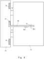
- Fig. 4 is a diagram for explaining a procedure of the inspection on the mold device 3 according to the third embodiment.
- a scale 50 is applied to the frame 10 along the machined surface 41.
- the mobile mold base 12 is provided with dimensional reference lines RL1 and RL2 formed at positions relative to the machined surface 41.
- the base-side reference line RL1 is, for example, a line provided to intersect vertically with the machined surface 41.
- the base-side reference line RL2 is, for example, a line parallel to the machined surface 41 at a certain distance from the machined surface 41.
- the scale 50 is provided with a scale-side reference line SL at a position matching the base-side reference line RL2.
- the scale 50 is applied to the machined surface 41 to check whether or not the base-side reference line RL1 is parallel to the side of the scale 50 and whether or not the base-side reference line RL1 overlaps the scale-side reference line SL, so as to check whether or not the mobile mold base 12 is inclined from a reference position.
- the machined surface 41 is not shown in Fig. 4 , by using the machined surface 41, it is easy to apply the scale 50 at defined inclination and position.
- the inclination of the mobile mold base 12 can be easily checked in the mold device 3 according to the third embodiment.
- the mobile mold base 12 tends to be inclined due to aging deterioration. By making it easy to check this inclination, processing for maintaining the mold device 3 can be simplified.
- a fourth embodiment another form of the mold device 1 according to the first embodiment will be described.
- the same components as those described in the first embodiment are assigned the same symbols as those in the first embodiment, and the description thereof is omitted.
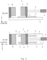
- Fig. 5 is an overview diagram of a mold device according to a fourth embodiment.
- the frame 10 is provided below the fixed mold base 11 and the mobile mold base 12.
- the frame 10 can also be provided below the fixed mold base 11 and the mobile mold base 12 rather than on the side of the fixed mold base 11 and the mobile mold base 12.
Landscapes
- Engineering & Computer Science (AREA)
- Mechanical Engineering (AREA)
- Manufacturing & Machinery (AREA)
- Moulds For Moulding Plastics Or The Like (AREA)
- Media Introduction/Drainage Providing Device (AREA)
- Casting Devices For Molds (AREA)
Abstract
Description
- The present disclosure relates to a mold device, for example, a mold device including a mold for molding a sand mold.
- For example,
Japanese Patent No. 2610197 Fig. 1 ofJapanese Patent No. 2610197 - However, when the mobile mold is held by the tie bar, a frame for the structure to support the tie bar becomes large, which creates a problem of increasing restrictions on the installation.
- The present disclosure has been made in order to solve such a problem, and an object thereof is to reduce the restrictions on the installation of a mold device.
- In an example aspect of the present disclosure, a mold device includes: a fixed mold base for supporting a fixed mold; a mobile mold base for supporting a mobile mold; a frame to which the fixed mold base is fixed, provided to extend in a direction in which the mobile mold base is moved, and formed into a wall shape; and holding means for movably supporting the mobile mold base to the frame.
- The frame is provided along at least one side of the mobile mold base except an upper surface thereof with the mold device installed, and the holding means supports the mobile mold base at one side of the mobile mold base.
- In the mold device according to the present disclosure, the mobile mold base is cantilevered and supported.
- According to the mold device of the present disclosure, it is possible to reduce the restrictions on the installation of a mold device.
- The above and other objects, features and advantages of the present disclosure will become more fully understood from the detailed description given hereinbelow and the accompanying drawings which are given by way of illustration only, and thus are not to be considered as limiting the present disclosure.
-
-
Fig. 1 is an overview diagram of a mold device according to a first embodiment; -
Fig. 2 is an overview diagram of a mold device according to a second embodiment; -
Fig. 3 is an overview diagram of a mold device according to a third embodiment; -
Fig. 4 is a diagram for explaining a procedure of an inspection on the mold device according to the third embodiment; and -
Fig. 5 is an overview diagram of a mold device according to a fourth embodiment. - First,
Fig. 1 is an overview diagram of amold device 1 according to a first embodiment. InFig. 1 , a side view of a device viewed from the side when themold device 1 is installed is shown in the upper part of the drawing, and a top view of the device viewed from the top is shown in the lower part thereof. - As shown in
Fig. 1 , themold device 1 according to the first embodiment includes aframe 10, a fixedmold base 11, amobile mold base 12, holding means (e.g.,rails 13 and guides 14), and driving means (acylinder 15 and a plunger 16). Themold device 1 further includes a fixedmold 20 and amobile mold 21. Thefixed mold 20 is supported by thefixed mold base 11. Themobile mold 21 is supported by themobile mold base 12. The fixedmold 20 and themobile mold 21 are replaced by a molded product to be manufactured. - The
frame 10 is connected so that theframe 10 is fixed in such a way thefixed mold base 11 is movable. Theframe 10 is then formed into a wall shape extending in a direction in which thefixed mold base 11 is moved. Thefixed mold base 11 supports thefixed mold 20. Themobile mold base 12 supports themobile mold 21 along at least one side of themobile mold 21. - In the example shown in
Fig. 1 , support means movably supports the fixedmold base 11 to theframe 10. In the example shown inFig. 1 , a combination of therails 13 and theguides 14 is used as the support means. Therails 13 are fixed to thefixed mold base 11. Theguides 14 are fitted into the rails so as to be movable on the rail and fixed to themobile mold base 12. - In the example shown in
Fig. 1 , the driving means employs a combination of thecylinder 15 and theplunger 16. Theplunger 16 is connected to a central part of themobile mold base 12. Thecylinder 15 moves themobile mold base 12 laterally (e.g., in a Y direction) inFig. 1 by sliding theplunger 16 in directions in which theplunger 16 is extruded and extruded back. - Here, in the
mold device 1 according to the first embodiment, theframe 10 is provided along at least one side of themolding device 1 except an upper surface of themobile mold base 12 with the mold device installed, and the holding means supports the mobile mold base at one side of themobile mold base 12. In the example shown inFig. 1 , theframe 10 is provided along one side of themobile mold base 12. That is, themobile mold base 12 is cantilevered and supported in themold device 1 according to the first embodiment shown inFig. 2 . Themold device 1 according to the first embodiment is specifically configured so that no other structure covers an area where the fixedmold 20 and themobile mold 21 are brought into contact with each other. - In the
mold device 1 according to the first embodiment, mold sand is charged into a mold formed by the fixedmold 20 and themobile mold 21 from an upper side of the device (e.g., from a Z direction). Therefore, a part of the upper surface of themold device 1 where the fixedmold 20 is brought into contact with themobile mold 21 must be exposed. - In the example shown in
Fig. 1 , theframe 10, thefixed mold base 11, themobile mold base 12, theguides 14, thecylinder 15, and theplunger 16 are shown exposed, but they may have a cover. In this case, the cover is provided with an opening around the area where the fixedmold 20 and themobile mold 21 are brought into contact with each other. - As shown in
Fig. 1 , in themold device 1 according to the first embodiment, theguides 14 and therails 13 are used as the support means for themobile mold base 12, so that the structure to support the support means itself, such as the tie bar, is not required and a total volume of the device can be reduced. - Therefore, even if each of the two opposing sides of the
mobile mold base 12 is supported by therail 13 and theguide 14, it is possible to reduce the total volume of themold device 1 according to the first embodiment, because a structure to support the support means itself, such as a tie bar, is unnecessary. However, the effect of the reduction in the total volume of themold device 1 according to the first embodiment is smaller than that of themold device 1 with the cantilever support structure shown inFig. 1 . - In the example shown in
Fig. 1 , therails 13 andguides 14 are shown as the support means. Alternatively, the rails can be replaced with ball screws and actuators for rotating the ball screws may be added. If ball screws are used, screw holes must be provided in themobile mold base 12 to engage the ball screws. Thus, even when a combination of ball screws and actuators is used, the total volume of themold device 1 can be reduced, because the structure for supporting the ball screws can be very simple. - In addition, in the
mold device 1 according to the first embodiment, the support means is fixed only to theframe 10 and there are no restrictions on other parts, so that the degree of freedom of installation of control equipment and the like associated with themold device 1 can be increased. - In a second embodiment, another form of the
mold device 1 according to the first embodiment will be described. In the description of the second embodiment, the same components as those described in the first embodiment are assigned the same signs as those in the first embodiment, and the description thereof is omitted. -
Fig. 2 is an overview diagram of amold device 2 according to the second embodiment. As shown inFig. 2 , themold device 2 according to the second embodiment includes a fixedmold 30 and amobile mold 31 instead of the fixedmold 20 and themobile mold 21. The fixedmold 30 is the fixedmold 20 further including a fixedmold positioning key 30a. Themobile mold 31 is themobile mold 21 further including a mobilemold positioning key 31a. The fixedmold positioning key 30a and the mobilemold positioning key 31a are a recess and a projection, respectively, that fit to each other when the fixedmold 30 and themobile mold 31 are put together, as shown in an area A of the lower drawing ofFig. 2 . In another aspect, one pair of a recessed positioning key and a projected positioning key is formed in the fixedmold 20, and another pair of a recessed positioning key and a projected positioning key is formed in themobile mold 21. - These positioning keys are provided on one or more sides including at least the side opposite to the side on which the holding means (e.g., guides 14) is provided. In the example shown in
Fig. 2 , themovable positioning key 31a is provided on the side of themobile mold base 12 opposite to the side where theguide 14 is provided among the sides of themobile mold base 12. Thefixed positioning key 30a is provided on the side corresponding to the side where the mobilemold positioning key 31a is provided among the sides of the fixedmold 30. - By providing the positioning keys in this way, it becomes easy to position the fixed
mold base 30 and themobile mold base 31 when the fixedmold base 30 and themobile mold base 31 are attached to the fixedmold base 11 and themobile mold base 12, respectively. In addition, by forming the positioning keys on the side of the fixedmold 30 where theguides 14 are provided, positioning accuracy can be further improved than in the example shown inFig. 2 . - The positioning keys are preferably provided near the center of the side where the
guides 14 are to be provided. By providing positioning keys near a center of the side, it is possible to reduce the displacement of key positions due to thermal expansion of the mold. - In a third embodiment, another form of the
mold device 1 according to the first embodiment will be described. In the description of the third embodiment, the same components as those described in the first embodiment are assigned the same symbols as those in the first embodiment, and the description thereof is omitted. -
Fig. 3 is an overview diagram of amold device 3 according to the third embodiment. As shown inFig. 3 , themold device 3 according to the third embodiment includes ascale guide 40 on theframe 10.Fig. 3 shows an enlarged view of thescale guide 40. As shown inFig. 3 , thescale guide 40 includes at least onemachined surface 41 formed with a preset degree of verticality and flatness. Aguide jig 42 can be attached to the machinedsurface 41. Theguide jig 42 may be attached at the time of an inspection described later or may be installed regularly. - Here, an inspection using the
scale guide 40 is described.Fig. 4 is a diagram for explaining a procedure of the inspection on themold device 3 according to the third embodiment. As shown inFig. 4 , at the time of an inspection, ascale 50 is applied to theframe 10 along the machinedsurface 41. Themobile mold base 12 is provided with dimensional reference lines RL1 and RL2 formed at positions relative to the machinedsurface 41. The base-side reference line RL1 is, for example, a line provided to intersect vertically with the machinedsurface 41. The base-side reference line RL2 is, for example, a line parallel to the machinedsurface 41 at a certain distance from the machinedsurface 41. Thescale 50 is provided with a scale-side reference line SL at a position matching the base-side reference line RL2. Next, thescale 50 is applied to the machinedsurface 41 to check whether or not the base-side reference line RL1 is parallel to the side of thescale 50 and whether or not the base-side reference line RL1 overlaps the scale-side reference line SL, so as to check whether or not themobile mold base 12 is inclined from a reference position. Although the machinedsurface 41 is not shown inFig. 4 , by using the machinedsurface 41, it is easy to apply thescale 50 at defined inclination and position. - In this way, by using the
scale guide 40, the inclination of themobile mold base 12 can be easily checked in themold device 3 according to the third embodiment. In themold device 3 having the cantilevered structure, themobile mold base 12 tends to be inclined due to aging deterioration. By making it easy to check this inclination, processing for maintaining themold device 3 can be simplified. - In a fourth embodiment, another form of the
mold device 1 according to the first embodiment will be described. In the description of the fourth embodiment, the same components as those described in the first embodiment are assigned the same symbols as those in the first embodiment, and the description thereof is omitted. -
Fig. 5 is an overview diagram of a mold device according to a fourth embodiment. As shown inFig. 5 , in the fourth embodiment, theframe 10 is provided below the fixedmold base 11 and themobile mold base 12. In this way, theframe 10 can also be provided below the fixedmold base 11 and themobile mold base 12 rather than on the side of the fixedmold base 11 and themobile mold base 12. By installing theframe 10 in this way, it is possible to reduce the width of the device in a depth direction (X direction inFig. 5 ). By reducing the size of the device in the depth direction in this way, the footprint area at the time of the installation of the device can be reduced. - From the disclosure thus described, it will be obvious that the embodiments of the disclosure may be varied in many ways. Such variations are not to be regarded as a departure from the spirit and scope of the disclosure, and all such modifications as would be obvious to one skilled in the art are intended for inclusion within the scope of the following claims.
Claims (8)
- A mold device comprising:a fixed mold base (11) for supporting a fixed mold (20);a mobile mold base (12) for supporting a mobile mold (21);a frame (10) to which the fixed mold base (11) is fixed, provided to extend in a direction in which the mobile mold base (12) is moved, and formed into a wall shape; andholding means for movably supporting the mobile mold base (12) to the frame (10), whereinthe frame (10) is provided along at least one side of the mobile mold base (12) except an upper surface thereof with the mold device installed, andthe holding means supports the mobile mold base (12) at one side of the mobile mold base (12).
- The mold device according to Claim 1, wherein
the fixed mold (20) and the mobile mold (21) includes a positioning key (30a, 31a), the positioning key (30a, 31a) being a pair of positioning recess and a positioning projection, one of the poisoning recess and the poisoning projection being formed in the fixed mold (20) and another one of the poisoning recess and the poisoning projection being formed in the mobile mold (21). - The mold device according to Claim 2, wherein
the positioning key (30a, 31a) is provided on one or more sides including at least a side opposite to the holding means. - The mold device according to any one of Claims 1 to 3, whereina machined surface (41) is formed in the frame (10) at a preset degree of verticality and flatness, andthe mobile mold base (12) is provided with a dimensional reference line formed at a position relative to the machined surface (41).
- The mold device according to any one of Claims 1 to 4, further comprising:driving means (15, 16) for moving the mobile mold base (12), whereinthe driving means (15, 16) moves the mobile mold base (12) by pressing a center of the mobile mold base (12).
- The mold device according to any one of Claims 1 to 5, wherein
the holding means comprises:a rail (13) fixed to the frame (10); anda guide (14) fit into the rail in such a way that the guide can move on the rail and fixed to the mobile mold base (12). - The mold device according to any one of Claims 1 to 6, wherein the frame (10) is disposed on a side surface of the mobile mold base (12) with the mold device installed.
- The mold device according to any one of Claims 1 to 6, wherein the frame (10) is disposed below the mobile mold base (12) with the mold device installed.
Applications Claiming Priority (1)
| Application Number | Priority Date | Filing Date | Title |
|---|---|---|---|
| JP2022029489A JP2023125419A (en) | 2022-02-28 | 2022-02-28 | mold equipment |
Publications (2)
| Publication Number | Publication Date |
|---|---|
| EP4234121A1 true EP4234121A1 (en) | 2023-08-30 |
| EP4234121B1 EP4234121B1 (en) | 2024-05-08 |
Family
ID=84942878
Family Applications (1)
| Application Number | Title | Priority Date | Filing Date |
|---|---|---|---|
| EP23151352.4A Active EP4234121B1 (en) | 2022-02-28 | 2023-01-12 | Mold device |
Country Status (4)
| Country | Link |
|---|---|
| US (1) | US12420455B2 (en) |
| EP (1) | EP4234121B1 (en) |
| JP (1) | JP2023125419A (en) |
| CN (1) | CN116652107A (en) |
Citations (6)
| Publication number | Priority date | Publication date | Assignee | Title |
|---|---|---|---|---|
| US3704973A (en) * | 1971-06-08 | 1972-12-05 | Husky Mfg & Toolworks Ltd | Electro-hydraulic means for opening and closing injection molds |
| EP0381107A2 (en) * | 1989-01-30 | 1990-08-08 | Ube Industries, Ltd. | Mold clamping apparatus for molding machine |
| US5356279A (en) * | 1991-12-03 | 1994-10-18 | Hemscheidt Maschinentechnik Schwerin Gmbh & Co. | Machine frame with a movable scaffold for the tool area of an injection molding machine |
| JP2610197B2 (en) | 1990-07-31 | 1997-05-14 | ファナック株式会社 | Core exchange mechanism |
| US20030150586A1 (en) * | 2001-12-26 | 2003-08-14 | Yoshiki Matsuura | Molding die and die changing method of the same |
| JP4323900B2 (en) * | 2003-09-05 | 2009-09-02 | 大和化成工業株式会社 | Electric injection molding equipment |
Family Cites Families (15)
| Publication number | Priority date | Publication date | Assignee | Title |
|---|---|---|---|---|
| JPS473010B1 (en) * | 1967-11-10 | 1972-01-27 | ||
| JPS5941081Y2 (en) * | 1980-09-12 | 1984-11-26 | 株式会社日本製鋼所 | Mold mounting device for injection molding machine |
| JP2972228B2 (en) * | 1989-07-04 | 1999-11-08 | 株式会社新興セルビック | Alignment structure of resin mold |
| US5249951A (en) * | 1991-10-25 | 1993-10-05 | Engel Maschinenbau Gesellschaft M.B.H. | Injection molding machine having tiltable mounting plates |
| ATE185312T1 (en) * | 1993-09-30 | 1999-10-15 | Karl Hehl | INJECTION MOLDING MACHINE FOR PROCESSING PLASTIFIABLE COMPOUNDS |
| AT400233B (en) * | 1994-05-17 | 1995-11-27 | Engel Gmbh Maschbau | HOLHLESS INJECTION MOLDING MACHINE |
| DE4443689A1 (en) * | 1994-12-08 | 1996-06-13 | Krauss Maffei Ag | Closing unit for an injection molding machine |
| JPH10217302A (en) * | 1997-02-03 | 1998-08-18 | Toshiba Mach Co Ltd | Injection molding machine |
| JP2000254765A (en) * | 1999-03-10 | 2000-09-19 | Akihisa Inoue | Melt-forging method, mold for performing the forging method, and melt-forging apparatus using the mold |
| JP2002046154A (en) * | 2000-08-02 | 2002-02-12 | Ikuyo Co Ltd | Door trim mold structure and door trim manufacturing method |
| JP2007245398A (en) * | 2006-03-14 | 2007-09-27 | Tokai Rika Co Ltd | Mold assembly |
| JP2010089295A (en) * | 2008-10-06 | 2010-04-22 | Sodick Plastech Co Ltd | Horizontal mold clamping device for injection molding machine |
| AT506017A1 (en) * | 2007-10-23 | 2009-05-15 | Engel Austria Gmbh | INJECTION MOLDING |
| PL3486003T3 (en) * | 2017-11-17 | 2020-11-02 | Nemak, S.A.B. De C.V. | Casting apparatus for producing castings from a metallic melt |
| AT524787B1 (en) * | 2021-07-01 | 2022-09-15 | Woojin Plaimm Gmbh | Columnless clamping unit for an injection molding device |
-
2022
- 2022-02-28 JP JP2022029489A patent/JP2023125419A/en active Pending
-
2023
- 2023-01-12 EP EP23151352.4A patent/EP4234121B1/en active Active
- 2023-01-24 US US18/158,819 patent/US12420455B2/en active Active
- 2023-02-27 CN CN202310170897.1A patent/CN116652107A/en active Pending
Patent Citations (6)
| Publication number | Priority date | Publication date | Assignee | Title |
|---|---|---|---|---|
| US3704973A (en) * | 1971-06-08 | 1972-12-05 | Husky Mfg & Toolworks Ltd | Electro-hydraulic means for opening and closing injection molds |
| EP0381107A2 (en) * | 1989-01-30 | 1990-08-08 | Ube Industries, Ltd. | Mold clamping apparatus for molding machine |
| JP2610197B2 (en) | 1990-07-31 | 1997-05-14 | ファナック株式会社 | Core exchange mechanism |
| US5356279A (en) * | 1991-12-03 | 1994-10-18 | Hemscheidt Maschinentechnik Schwerin Gmbh & Co. | Machine frame with a movable scaffold for the tool area of an injection molding machine |
| US20030150586A1 (en) * | 2001-12-26 | 2003-08-14 | Yoshiki Matsuura | Molding die and die changing method of the same |
| JP4323900B2 (en) * | 2003-09-05 | 2009-09-02 | 大和化成工業株式会社 | Electric injection molding equipment |
Also Published As
| Publication number | Publication date |
|---|---|
| EP4234121B1 (en) | 2024-05-08 |
| JP2023125419A (en) | 2023-09-07 |
| CN116652107A (en) | 2023-08-29 |
| US20230271351A1 (en) | 2023-08-31 |
| US12420455B2 (en) | 2025-09-23 |
Similar Documents
| Publication | Publication Date | Title |
|---|---|---|
| US7140872B2 (en) | Molding machine | |
| CN219852607U (en) | Laser processing device and laser processing equipment | |
| EP4234121A1 (en) | Mold device | |
| CN112901968A (en) | Linear guide rail type lifting platform and laser direct-writing type imaging equipment | |
| US6372179B1 (en) | Metal plate cutting machine | |
| EP1396014B1 (en) | Apparatus for the measurement or machining of an object, provided with a displacement stage with wedge-shaped guides | |
| CN216792586U (en) | Adopt no vibration XY motion platform of gantry structure | |
| CN213843753U (en) | Precision positioning stepping system for direct-write lithography machine and direct-write lithography machine | |
| CN216927079U (en) | Laser range finder calibrating device | |
| JP2017013210A (en) | Biaxial positioning stage apparatus | |
| CN216051197U (en) | Rolling test equipment | |
| CN219598049U (en) | Side accurate positioning die carrier | |
| CN114200666A (en) | Non-vibration XY motion platform adopting gantry structure | |
| KR20130048197A (en) | Parallel slider device of pneumatic linear guide method, control method of same, and measurement device | |
| CN115138998A (en) | Gantry double-drive linear motion platform | |
| JPH0755837B2 (en) | Optical lens press molding equipment | |
| JP4391981B2 (en) | Mold moving mechanism for injection molding machine | |
| CN210881053U (en) | Inclined plane guide mechanism of digital servo hydraulic press | |
| CN218696404U (en) | CNC tool magazine and CNC processing equipment | |
| CN219301523U (en) | Large-stroke image instrument | |
| JPH0784024B2 (en) | Mold fixing device in injection molding machine | |
| CN221984485U (en) | A fast automatic positioning device for CNC machining | |
| CN220660663U (en) | Positioning device of lamp panel module | |
| CN222103536U (en) | A carrying device and optical equipment | |
| CN118162920B (en) | Linear shaft of numerical control machine and numerical control machine |
Legal Events
| Date | Code | Title | Description |
|---|---|---|---|
| PUAI | Public reference made under article 153(3) epc to a published international application that has entered the european phase |
Free format text: ORIGINAL CODE: 0009012 |
|
| STAA | Information on the status of an ep patent application or granted ep patent |
Free format text: STATUS: REQUEST FOR EXAMINATION WAS MADE |
|
| 17P | Request for examination filed |
Effective date: 20230112 |
|
| AK | Designated contracting states |
Kind code of ref document: A1 Designated state(s): AL AT BE BG CH CY CZ DE DK EE ES FI FR GB GR HR HU IE IS IT LI LT LU LV MC ME MK MT NL NO PL PT RO RS SE SI SK SM TR |
|
| STAA | Information on the status of an ep patent application or granted ep patent |
Free format text: STATUS: EXAMINATION IS IN PROGRESS |
|
| 17Q | First examination report despatched |
Effective date: 20231113 |
|
| GRAP | Despatch of communication of intention to grant a patent |
Free format text: ORIGINAL CODE: EPIDOSNIGR1 |
|
| STAA | Information on the status of an ep patent application or granted ep patent |
Free format text: STATUS: GRANT OF PATENT IS INTENDED |
|
| RIC1 | Information provided on ipc code assigned before grant |
Ipc: B22C 15/08 20060101ALI20240220BHEP Ipc: B22C 13/06 20060101ALI20240220BHEP Ipc: B22C 11/00 20060101ALI20240220BHEP Ipc: B29C 45/66 20060101ALI20240220BHEP Ipc: B29C 45/17 20060101ALI20240220BHEP Ipc: B22D 17/26 20060101ALI20240220BHEP Ipc: B22D 17/22 20060101ALI20240220BHEP Ipc: B22D 17/20 20060101ALI20240220BHEP Ipc: B22D 17/10 20060101AFI20240220BHEP |
|
| GRAS | Grant fee paid |
Free format text: ORIGINAL CODE: EPIDOSNIGR3 |
|
| INTG | Intention to grant announced |
Effective date: 20240307 |
|
| RIN1 | Information on inventor provided before grant (corrected) |
Inventor name: HAMAGUCHI, HIROYUKI Inventor name: KAWAI, AKINOBU Inventor name: NAKAYAMA, SO Inventor name: WATANABE, HIROTSUNE |
|
| GRAA | (expected) grant |
Free format text: ORIGINAL CODE: 0009210 |
|
| STAA | Information on the status of an ep patent application or granted ep patent |
Free format text: STATUS: THE PATENT HAS BEEN GRANTED |
|
| AK | Designated contracting states |
Kind code of ref document: B1 Designated state(s): AL AT BE BG CH CY CZ DE DK EE ES FI FR GB GR HR HU IE IS IT LI LT LU LV MC ME MK MT NL NO PL PT RO RS SE SI SK SM TR |
|
| REG | Reference to a national code |
Ref country code: GB Ref legal event code: FG4D |
|
| REG | Reference to a national code |
Ref country code: CH Ref legal event code: EP |
|
| REG | Reference to a national code |
Ref country code: DE Ref legal event code: R096 Ref document number: 602023000084 Country of ref document: DE |
|
| REG | Reference to a national code |
Ref country code: IE Ref legal event code: FG4D |
|
| REG | Reference to a national code |
Ref country code: LT Ref legal event code: MG9D |
|
| REG | Reference to a national code |
Ref country code: NL Ref legal event code: MP Effective date: 20240508 |
|
| PG25 | Lapsed in a contracting state [announced via postgrant information from national office to epo] |
Ref country code: IS Free format text: LAPSE BECAUSE OF FAILURE TO SUBMIT A TRANSLATION OF THE DESCRIPTION OR TO PAY THE FEE WITHIN THE PRESCRIBED TIME-LIMIT Effective date: 20240908 |
|
| PG25 | Lapsed in a contracting state [announced via postgrant information from national office to epo] |
Ref country code: BG Free format text: LAPSE BECAUSE OF FAILURE TO SUBMIT A TRANSLATION OF THE DESCRIPTION OR TO PAY THE FEE WITHIN THE PRESCRIBED TIME-LIMIT Effective date: 20240508 |
|
| PG25 | Lapsed in a contracting state [announced via postgrant information from national office to epo] |
Ref country code: HR Free format text: LAPSE BECAUSE OF FAILURE TO SUBMIT A TRANSLATION OF THE DESCRIPTION OR TO PAY THE FEE WITHIN THE PRESCRIBED TIME-LIMIT Effective date: 20240508 Ref country code: FI Free format text: LAPSE BECAUSE OF FAILURE TO SUBMIT A TRANSLATION OF THE DESCRIPTION OR TO PAY THE FEE WITHIN THE PRESCRIBED TIME-LIMIT Effective date: 20240508 |
|
| PG25 | Lapsed in a contracting state [announced via postgrant information from national office to epo] |
Ref country code: GR Free format text: LAPSE BECAUSE OF FAILURE TO SUBMIT A TRANSLATION OF THE DESCRIPTION OR TO PAY THE FEE WITHIN THE PRESCRIBED TIME-LIMIT Effective date: 20240809 |
|
| PG25 | Lapsed in a contracting state [announced via postgrant information from national office to epo] |
Ref country code: PT Free format text: LAPSE BECAUSE OF FAILURE TO SUBMIT A TRANSLATION OF THE DESCRIPTION OR TO PAY THE FEE WITHIN THE PRESCRIBED TIME-LIMIT Effective date: 20240909 |
|
| REG | Reference to a national code |
Ref country code: AT Ref legal event code: MK05 Ref document number: 1684583 Country of ref document: AT Kind code of ref document: T Effective date: 20240508 |
|
| PG25 | Lapsed in a contracting state [announced via postgrant information from national office to epo] |
Ref country code: NL Free format text: LAPSE BECAUSE OF FAILURE TO SUBMIT A TRANSLATION OF THE DESCRIPTION OR TO PAY THE FEE WITHIN THE PRESCRIBED TIME-LIMIT Effective date: 20240508 |
|
| PG25 | Lapsed in a contracting state [announced via postgrant information from national office to epo] |
Ref country code: ES Free format text: LAPSE BECAUSE OF FAILURE TO SUBMIT A TRANSLATION OF THE DESCRIPTION OR TO PAY THE FEE WITHIN THE PRESCRIBED TIME-LIMIT Effective date: 20240508 |
|
| PG25 | Lapsed in a contracting state [announced via postgrant information from national office to epo] |
Ref country code: AT Free format text: LAPSE BECAUSE OF FAILURE TO SUBMIT A TRANSLATION OF THE DESCRIPTION OR TO PAY THE FEE WITHIN THE PRESCRIBED TIME-LIMIT Effective date: 20240508 |
|
| PG25 | Lapsed in a contracting state [announced via postgrant information from national office to epo] |
Ref country code: PL Free format text: LAPSE BECAUSE OF FAILURE TO SUBMIT A TRANSLATION OF THE DESCRIPTION OR TO PAY THE FEE WITHIN THE PRESCRIBED TIME-LIMIT Effective date: 20240508 |
|
| PG25 | Lapsed in a contracting state [announced via postgrant information from national office to epo] |
Ref country code: LV Free format text: LAPSE BECAUSE OF FAILURE TO SUBMIT A TRANSLATION OF THE DESCRIPTION OR TO PAY THE FEE WITHIN THE PRESCRIBED TIME-LIMIT Effective date: 20240508 |
|
| PG25 | Lapsed in a contracting state [announced via postgrant information from national office to epo] |
Ref country code: PT Free format text: LAPSE BECAUSE OF FAILURE TO SUBMIT A TRANSLATION OF THE DESCRIPTION OR TO PAY THE FEE WITHIN THE PRESCRIBED TIME-LIMIT Effective date: 20240909 Ref country code: PL Free format text: LAPSE BECAUSE OF FAILURE TO SUBMIT A TRANSLATION OF THE DESCRIPTION OR TO PAY THE FEE WITHIN THE PRESCRIBED TIME-LIMIT Effective date: 20240508 Ref country code: NO Free format text: LAPSE BECAUSE OF FAILURE TO SUBMIT A TRANSLATION OF THE DESCRIPTION OR TO PAY THE FEE WITHIN THE PRESCRIBED TIME-LIMIT Effective date: 20240808 Ref country code: NL Free format text: LAPSE BECAUSE OF FAILURE TO SUBMIT A TRANSLATION OF THE DESCRIPTION OR TO PAY THE FEE WITHIN THE PRESCRIBED TIME-LIMIT Effective date: 20240508 Ref country code: LV Free format text: LAPSE BECAUSE OF FAILURE TO SUBMIT A TRANSLATION OF THE DESCRIPTION OR TO PAY THE FEE WITHIN THE PRESCRIBED TIME-LIMIT Effective date: 20240508 Ref country code: IS Free format text: LAPSE BECAUSE OF FAILURE TO SUBMIT A TRANSLATION OF THE DESCRIPTION OR TO PAY THE FEE WITHIN THE PRESCRIBED TIME-LIMIT Effective date: 20240908 Ref country code: HR Free format text: LAPSE BECAUSE OF FAILURE TO SUBMIT A TRANSLATION OF THE DESCRIPTION OR TO PAY THE FEE WITHIN THE PRESCRIBED TIME-LIMIT Effective date: 20240508 Ref country code: GR Free format text: LAPSE BECAUSE OF FAILURE TO SUBMIT A TRANSLATION OF THE DESCRIPTION OR TO PAY THE FEE WITHIN THE PRESCRIBED TIME-LIMIT Effective date: 20240809 Ref country code: FI Free format text: LAPSE BECAUSE OF FAILURE TO SUBMIT A TRANSLATION OF THE DESCRIPTION OR TO PAY THE FEE WITHIN THE PRESCRIBED TIME-LIMIT Effective date: 20240508 Ref country code: ES Free format text: LAPSE BECAUSE OF FAILURE TO SUBMIT A TRANSLATION OF THE DESCRIPTION OR TO PAY THE FEE WITHIN THE PRESCRIBED TIME-LIMIT Effective date: 20240508 Ref country code: BG Free format text: LAPSE BECAUSE OF FAILURE TO SUBMIT A TRANSLATION OF THE DESCRIPTION OR TO PAY THE FEE WITHIN THE PRESCRIBED TIME-LIMIT Effective date: 20240508 Ref country code: AT Free format text: LAPSE BECAUSE OF FAILURE TO SUBMIT A TRANSLATION OF THE DESCRIPTION OR TO PAY THE FEE WITHIN THE PRESCRIBED TIME-LIMIT Effective date: 20240508 Ref country code: RS Free format text: LAPSE BECAUSE OF FAILURE TO SUBMIT A TRANSLATION OF THE DESCRIPTION OR TO PAY THE FEE WITHIN THE PRESCRIBED TIME-LIMIT Effective date: 20240808 |
|
| P01 | Opt-out of the competence of the unified patent court (upc) registered |
Free format text: CASE NUMBER: APP_57273/2024 Effective date: 20241019 |
|
| REG | Reference to a national code |
Ref country code: DE Ref legal event code: R084 Ref document number: 602023000084 Country of ref document: DE |
|
| PG25 | Lapsed in a contracting state [announced via postgrant information from national office to epo] |
Ref country code: DK Free format text: LAPSE BECAUSE OF FAILURE TO SUBMIT A TRANSLATION OF THE DESCRIPTION OR TO PAY THE FEE WITHIN THE PRESCRIBED TIME-LIMIT Effective date: 20240508 |
|
| PG25 | Lapsed in a contracting state [announced via postgrant information from national office to epo] |
Ref country code: EE Free format text: LAPSE BECAUSE OF FAILURE TO SUBMIT A TRANSLATION OF THE DESCRIPTION OR TO PAY THE FEE WITHIN THE PRESCRIBED TIME-LIMIT Effective date: 20240508 |
|
| PG25 | Lapsed in a contracting state [announced via postgrant information from national office to epo] |
Ref country code: CZ Free format text: LAPSE BECAUSE OF FAILURE TO SUBMIT A TRANSLATION OF THE DESCRIPTION OR TO PAY THE FEE WITHIN THE PRESCRIBED TIME-LIMIT Effective date: 20240508 |
|
| PG25 | Lapsed in a contracting state [announced via postgrant information from national office to epo] |
Ref country code: SK Free format text: LAPSE BECAUSE OF FAILURE TO SUBMIT A TRANSLATION OF THE DESCRIPTION OR TO PAY THE FEE WITHIN THE PRESCRIBED TIME-LIMIT Effective date: 20240508 Ref country code: RO Free format text: LAPSE BECAUSE OF FAILURE TO SUBMIT A TRANSLATION OF THE DESCRIPTION OR TO PAY THE FEE WITHIN THE PRESCRIBED TIME-LIMIT Effective date: 20240508 |
|
| PG25 | Lapsed in a contracting state [announced via postgrant information from national office to epo] |
Ref country code: SM Free format text: LAPSE BECAUSE OF FAILURE TO SUBMIT A TRANSLATION OF THE DESCRIPTION OR TO PAY THE FEE WITHIN THE PRESCRIBED TIME-LIMIT Effective date: 20240508 |
|
| PG25 | Lapsed in a contracting state [announced via postgrant information from national office to epo] |
Ref country code: SM Free format text: LAPSE BECAUSE OF FAILURE TO SUBMIT A TRANSLATION OF THE DESCRIPTION OR TO PAY THE FEE WITHIN THE PRESCRIBED TIME-LIMIT Effective date: 20240508 Ref country code: SK Free format text: LAPSE BECAUSE OF FAILURE TO SUBMIT A TRANSLATION OF THE DESCRIPTION OR TO PAY THE FEE WITHIN THE PRESCRIBED TIME-LIMIT Effective date: 20240508 Ref country code: RO Free format text: LAPSE BECAUSE OF FAILURE TO SUBMIT A TRANSLATION OF THE DESCRIPTION OR TO PAY THE FEE WITHIN THE PRESCRIBED TIME-LIMIT Effective date: 20240508 Ref country code: EE Free format text: LAPSE BECAUSE OF FAILURE TO SUBMIT A TRANSLATION OF THE DESCRIPTION OR TO PAY THE FEE WITHIN THE PRESCRIBED TIME-LIMIT Effective date: 20240508 Ref country code: DK Free format text: LAPSE BECAUSE OF FAILURE TO SUBMIT A TRANSLATION OF THE DESCRIPTION OR TO PAY THE FEE WITHIN THE PRESCRIBED TIME-LIMIT Effective date: 20240508 Ref country code: CZ Free format text: LAPSE BECAUSE OF FAILURE TO SUBMIT A TRANSLATION OF THE DESCRIPTION OR TO PAY THE FEE WITHIN THE PRESCRIBED TIME-LIMIT Effective date: 20240508 |
|
| PG25 | Lapsed in a contracting state [announced via postgrant information from national office to epo] |
Ref country code: IT Free format text: LAPSE BECAUSE OF FAILURE TO SUBMIT A TRANSLATION OF THE DESCRIPTION OR TO PAY THE FEE WITHIN THE PRESCRIBED TIME-LIMIT Effective date: 20240508 |
|
| REG | Reference to a national code |
Ref country code: DE Ref legal event code: R097 Ref document number: 602023000084 Country of ref document: DE |
|
| PLBE | No opposition filed within time limit |
Free format text: ORIGINAL CODE: 0009261 |
|
| STAA | Information on the status of an ep patent application or granted ep patent |
Free format text: STATUS: NO OPPOSITION FILED WITHIN TIME LIMIT |
|
| 26N | No opposition filed |
Effective date: 20250211 |
|
| PG25 | Lapsed in a contracting state [announced via postgrant information from national office to epo] |
Ref country code: SI Free format text: LAPSE BECAUSE OF FAILURE TO SUBMIT A TRANSLATION OF THE DESCRIPTION OR TO PAY THE FEE WITHIN THE PRESCRIBED TIME-LIMIT Effective date: 20240508 |
|
| PG25 | Lapsed in a contracting state [announced via postgrant information from national office to epo] |
Ref country code: SE Free format text: LAPSE BECAUSE OF FAILURE TO SUBMIT A TRANSLATION OF THE DESCRIPTION OR TO PAY THE FEE WITHIN THE PRESCRIBED TIME-LIMIT Effective date: 20240508 |
|
| PG25 | Lapsed in a contracting state [announced via postgrant information from national office to epo] |
Ref country code: MC Free format text: LAPSE BECAUSE OF FAILURE TO SUBMIT A TRANSLATION OF THE DESCRIPTION OR TO PAY THE FEE WITHIN THE PRESCRIBED TIME-LIMIT Effective date: 20240508 Ref country code: LU Free format text: LAPSE BECAUSE OF NON-PAYMENT OF DUE FEES Effective date: 20250112 |
|
| PG25 | Lapsed in a contracting state [announced via postgrant information from national office to epo] |
Ref country code: BE Free format text: LAPSE BECAUSE OF NON-PAYMENT OF DUE FEES Effective date: 20250131 |
|
| PG25 | Lapsed in a contracting state [announced via postgrant information from national office to epo] |
Ref country code: FR Free format text: LAPSE BECAUSE OF NON-PAYMENT OF DUE FEES Effective date: 20250131 |
|
| REG | Reference to a national code |
Ref country code: BE Ref legal event code: MM Effective date: 20250131 |
|
| PG25 | Lapsed in a contracting state [announced via postgrant information from national office to epo] |
Ref country code: IE Free format text: LAPSE BECAUSE OF NON-PAYMENT OF DUE FEES Effective date: 20250112 |
|
| PGFP | Annual fee paid to national office [announced via postgrant information from national office to epo] |
Ref country code: DE Payment date: 20251203 Year of fee payment: 4 |