EP4233945B1 - Stiftnadelentfernungsvorrichtung für eine arzneimittelabgabevorrichtung - Google Patents
Stiftnadelentfernungsvorrichtung für eine arzneimittelabgabevorrichtung Download PDFInfo
- Publication number
- EP4233945B1 EP4233945B1 EP23170584.9A EP23170584A EP4233945B1 EP 4233945 B1 EP4233945 B1 EP 4233945B1 EP 23170584 A EP23170584 A EP 23170584A EP 4233945 B1 EP4233945 B1 EP 4233945B1
- Authority
- EP
- European Patent Office
- Prior art keywords
- pen needle
- ejector
- drug delivery
- cap
- delivery device
- Prior art date
- Legal status (The legal status is an assumption and is not a legal conclusion. Google has not performed a legal analysis and makes no representation as to the accuracy of the status listed.)
- Active
Links
Images





Classifications
-
- A—HUMAN NECESSITIES
- A61—MEDICAL OR VETERINARY SCIENCE; HYGIENE
- A61M—DEVICES FOR INTRODUCING MEDIA INTO, OR ONTO, THE BODY; DEVICES FOR TRANSDUCING BODY MEDIA OR FOR TAKING MEDIA FROM THE BODY; DEVICES FOR PRODUCING OR ENDING SLEEP OR STUPOR
- A61M5/00—Devices for bringing media into the body in a subcutaneous, intra-vascular or intramuscular way; Accessories therefor, e.g. filling or cleaning devices, arm-rests
- A61M5/178—Syringes
- A61M5/31—Details
- A61M5/32—Needles; Details of needles pertaining to their connection with syringe or hub; Accessories for bringing the needle into, or holding the needle on, the body; Devices for protection of needles
- A61M5/3202—Devices for protection of the needle before use, e.g. caps
-
- A—HUMAN NECESSITIES
- A61—MEDICAL OR VETERINARY SCIENCE; HYGIENE
- A61M—DEVICES FOR INTRODUCING MEDIA INTO, OR ONTO, THE BODY; DEVICES FOR TRANSDUCING BODY MEDIA OR FOR TAKING MEDIA FROM THE BODY; DEVICES FOR PRODUCING OR ENDING SLEEP OR STUPOR
- A61M5/00—Devices for bringing media into the body in a subcutaneous, intra-vascular or intramuscular way; Accessories therefor, e.g. filling or cleaning devices, arm-rests
- A61M5/178—Syringes
- A61M5/31—Details
- A61M5/32—Needles; Details of needles pertaining to their connection with syringe or hub; Accessories for bringing the needle into, or holding the needle on, the body; Devices for protection of needles
- A61M5/3205—Apparatus for removing or disposing of used needles or syringes, e.g. containers; Means for protection against accidental injuries from used needles
- A61M5/321—Means for protection against accidental injuries by used needles
- A61M5/3213—Caps placed axially onto the needle, e.g. equipped with finger protection guards
-
- A—HUMAN NECESSITIES
- A61—MEDICAL OR VETERINARY SCIENCE; HYGIENE
- A61M—DEVICES FOR INTRODUCING MEDIA INTO, OR ONTO, THE BODY; DEVICES FOR TRANSDUCING BODY MEDIA OR FOR TAKING MEDIA FROM THE BODY; DEVICES FOR PRODUCING OR ENDING SLEEP OR STUPOR
- A61M5/00—Devices for bringing media into the body in a subcutaneous, intra-vascular or intramuscular way; Accessories therefor, e.g. filling or cleaning devices, arm-rests
- A61M5/178—Syringes
- A61M5/31—Details
- A61M5/32—Needles; Details of needles pertaining to their connection with syringe or hub; Accessories for bringing the needle into, or holding the needle on, the body; Devices for protection of needles
- A61M5/3205—Apparatus for removing or disposing of used needles or syringes, e.g. containers; Means for protection against accidental injuries from used needles
- A61M5/3276—Means imparting rotational movement to the needle or needle hub in order to assist in its disconnection from syringe nozzle
-
- A—HUMAN NECESSITIES
- A61—MEDICAL OR VETERINARY SCIENCE; HYGIENE
- A61M—DEVICES FOR INTRODUCING MEDIA INTO, OR ONTO, THE BODY; DEVICES FOR TRANSDUCING BODY MEDIA OR FOR TAKING MEDIA FROM THE BODY; DEVICES FOR PRODUCING OR ENDING SLEEP OR STUPOR
- A61M5/00—Devices for bringing media into the body in a subcutaneous, intra-vascular or intramuscular way; Accessories therefor, e.g. filling or cleaning devices, arm-rests
- A61M5/178—Syringes
- A61M5/24—Ampoule syringes, i.e. syringes with needle for use in combination with replaceable ampoules or carpules, e.g. automatic
- A61M2005/2403—Ampoule inserted into the ampoule holder
- A61M2005/2407—Ampoule inserted into the ampoule holder from the rear
-
- A—HUMAN NECESSITIES
- A61—MEDICAL OR VETERINARY SCIENCE; HYGIENE
- A61M—DEVICES FOR INTRODUCING MEDIA INTO, OR ONTO, THE BODY; DEVICES FOR TRANSDUCING BODY MEDIA OR FOR TAKING MEDIA FROM THE BODY; DEVICES FOR PRODUCING OR ENDING SLEEP OR STUPOR
- A61M5/00—Devices for bringing media into the body in a subcutaneous, intra-vascular or intramuscular way; Accessories therefor, e.g. filling or cleaning devices, arm-rests
- A61M5/178—Syringes
- A61M5/31—Details
- A61M5/32—Needles; Details of needles pertaining to their connection with syringe or hub; Accessories for bringing the needle into, or holding the needle on, the body; Devices for protection of needles
- A61M5/3205—Apparatus for removing or disposing of used needles or syringes, e.g. containers; Means for protection against accidental injuries from used needles
- A61M2005/3206—Needle or needle hub disconnecting devices forming part of or being attached to the hub or syringe body
-
- A—HUMAN NECESSITIES
- A61—MEDICAL OR VETERINARY SCIENCE; HYGIENE
- A61M—DEVICES FOR INTRODUCING MEDIA INTO, OR ONTO, THE BODY; DEVICES FOR TRANSDUCING BODY MEDIA OR FOR TAKING MEDIA FROM THE BODY; DEVICES FOR PRODUCING OR ENDING SLEEP OR STUPOR
- A61M5/00—Devices for bringing media into the body in a subcutaneous, intra-vascular or intramuscular way; Accessories therefor, e.g. filling or cleaning devices, arm-rests
- A61M5/178—Syringes
- A61M5/31—Details
- A61M5/32—Needles; Details of needles pertaining to their connection with syringe or hub; Accessories for bringing the needle into, or holding the needle on, the body; Devices for protection of needles
- A61M5/3205—Apparatus for removing or disposing of used needles or syringes, e.g. containers; Means for protection against accidental injuries from used needles
- A61M2005/3208—Apparatus for removing or disposing of used needles or syringes, e.g. containers; Means for protection against accidental injuries from used needles by application of rotational movement to the needle hub, e.g. by use of electrically driven toothed wheels
-
- A—HUMAN NECESSITIES
- A61—MEDICAL OR VETERINARY SCIENCE; HYGIENE
- A61M—DEVICES FOR INTRODUCING MEDIA INTO, OR ONTO, THE BODY; DEVICES FOR TRANSDUCING BODY MEDIA OR FOR TAKING MEDIA FROM THE BODY; DEVICES FOR PRODUCING OR ENDING SLEEP OR STUPOR
- A61M2207/00—Methods of manufacture, assembly or production
- A61M2207/10—Device therefor
-
- A—HUMAN NECESSITIES
- A61—MEDICAL OR VETERINARY SCIENCE; HYGIENE
- A61M—DEVICES FOR INTRODUCING MEDIA INTO, OR ONTO, THE BODY; DEVICES FOR TRANSDUCING BODY MEDIA OR FOR TAKING MEDIA FROM THE BODY; DEVICES FOR PRODUCING OR ENDING SLEEP OR STUPOR
- A61M5/00—Devices for bringing media into the body in a subcutaneous, intra-vascular or intramuscular way; Accessories therefor, e.g. filling or cleaning devices, arm-rests
- A61M5/178—Syringes
- A61M5/24—Ampoule syringes, i.e. syringes with needle for use in combination with replaceable ampoules or carpules, e.g. automatic
-
- A—HUMAN NECESSITIES
- A61—MEDICAL OR VETERINARY SCIENCE; HYGIENE
- A61M—DEVICES FOR INTRODUCING MEDIA INTO, OR ONTO, THE BODY; DEVICES FOR TRANSDUCING BODY MEDIA OR FOR TAKING MEDIA FROM THE BODY; DEVICES FOR PRODUCING OR ENDING SLEEP OR STUPOR
- A61M5/00—Devices for bringing media into the body in a subcutaneous, intra-vascular or intramuscular way; Accessories therefor, e.g. filling or cleaning devices, arm-rests
- A61M5/178—Syringes
- A61M5/31—Details
- A61M5/315—Pistons; Piston-rods; Guiding, blocking or restricting the movement of the rod or piston; Appliances on the rod for facilitating dosing ; Dosing mechanisms
- A61M5/31525—Dosing
-
- A—HUMAN NECESSITIES
- A61—MEDICAL OR VETERINARY SCIENCE; HYGIENE
- A61M—DEVICES FOR INTRODUCING MEDIA INTO, OR ONTO, THE BODY; DEVICES FOR TRANSDUCING BODY MEDIA OR FOR TAKING MEDIA FROM THE BODY; DEVICES FOR PRODUCING OR ENDING SLEEP OR STUPOR
- A61M5/00—Devices for bringing media into the body in a subcutaneous, intra-vascular or intramuscular way; Accessories therefor, e.g. filling or cleaning devices, arm-rests
- A61M5/178—Syringes
- A61M5/31—Details
- A61M5/315—Pistons; Piston-rods; Guiding, blocking or restricting the movement of the rod or piston; Appliances on the rod for facilitating dosing ; Dosing mechanisms
- A61M5/31533—Dosing mechanisms, i.e. setting a dose
-
- Y—GENERAL TAGGING OF NEW TECHNOLOGICAL DEVELOPMENTS; GENERAL TAGGING OF CROSS-SECTIONAL TECHNOLOGIES SPANNING OVER SEVERAL SECTIONS OF THE IPC; TECHNICAL SUBJECTS COVERED BY FORMER USPC CROSS-REFERENCE ART COLLECTIONS [XRACs] AND DIGESTS
- Y10—TECHNICAL SUBJECTS COVERED BY FORMER USPC
- Y10T—TECHNICAL SUBJECTS COVERED BY FORMER US CLASSIFICATION
- Y10T29/00—Metal working
- Y10T29/49—Method of mechanical manufacture
- Y10T29/49815—Disassembling
- Y10T29/49822—Disassembling by applying force
-
- Y—GENERAL TAGGING OF NEW TECHNOLOGICAL DEVELOPMENTS; GENERAL TAGGING OF CROSS-SECTIONAL TECHNOLOGIES SPANNING OVER SEVERAL SECTIONS OF THE IPC; TECHNICAL SUBJECTS COVERED BY FORMER USPC CROSS-REFERENCE ART COLLECTIONS [XRACs] AND DIGESTS
- Y10—TECHNICAL SUBJECTS COVERED BY FORMER USPC
- Y10T—TECHNICAL SUBJECTS COVERED BY FORMER US CLASSIFICATION
- Y10T29/00—Metal working
- Y10T29/53—Means to assemble or disassemble
Definitions
- the present invention relates generally to a device for removing a pen needle from a drug delivery device. Still more particularly, the present invention relates to a pen cap that removes a pen needle from a drug delivery device and ejects the removed pen needle for proper disposal thereof.
- Insulin and other injectable medications are commonly given with drug delivery devices, such as a drug delivery pen, whereby a disposable pen needle is attached to facilitate drug container access and allow fluid egress from the container through the needle into the patient.
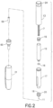
- FIG. 2 is an exploded view of the drug delivery pen 100 of FIG. 1 .
- the dose knob/button 24 has a dual purpose and is used both to set the dosage of the medication to be injected and to inject the dosed medicament via the leadscrew 7 and stopper 15 through the medicament cartridge 12, which is attached to the drug delivery pen through a lower housing 17.
- the dosing and delivery mechanisms are all found within the outer sleeve 13 and are not described in greater detail here as they are understood by those knowledgeable of the prior art.
- the distal movement of the plunger or stopper 15 within the medicament cartridge 12 causes medication to be forced into the needle 11 of the hub 20.
- the medicament cartridge 12 is sealed by septum 16, which is punctured by a septum penetrating needle cannula 18 located within the hub 20.
- the hub 20 is preferably screwed onto the lower housing 17, although other attachment means can be used, such as attaching to the cartridge 12.
- an outer cover 69 which attaches to the hub 20, covers the hub.
- An inner shield 59 covers the patient needle 11 within the outer cover 69.
- the inner shield 59 can be secured to the hub 20 to cover the patient needle by any suitable means, such as an interference fit or a snap fit.
- the outer cover 69 and the inner shield 59 are removed prior to use.
- the cap 21 fits snugly against outer sleeve 13 to allow a user to securely carry the drug delivery pen 100.
- the medicament cartridge 12 is typically a glass tube sealed at one end with the septum 16 and sealed at the other end with the stopper 15.
- the septum 16 is pierceable by a septum penetrating cannula 18 in the hub 20, but does not move with respect to the medicament cartridge 12.
- the stopper 15 is axially displaceable within the medicament cartridge 12 while maintaining a fluid tight seal.
- FIG. 3 An exploded perspective view of a pen needle 2 of an exemplary drug delivery pen is shown in FIG. 3 .
- the pen needle 2 includes the cover (outer shield) 69, an inner shield 59, a needle cannula 11, and a hub 20.
- a proximal end 310 of the needle cannula 11 is inserted into a center opening in the distal (patient) end 405 of the hub 20 until a predetermined length of the distal (patient) end 305 of the needle cannula 11 remains extended.
- the needle cannula 11 is secured by epoxy or adhesive in the distal end 405 of the hub 20 within the hub protrusion 420.
- the inner shield 59 covers the exposed portion of the needle cannula 11.
- the open proximal end 210 of the inner shield 59 is placed over the exposed portion of the needle cannula 11.
- the open proximal end 110 of the cover 69 envelops the inner shield 59, needle cannula 11, and hub 20.
- the distal end 105 of the cover 69 is closed to prevent contamination and damage to the inner components of the pen needle 2, and to prevent injury to anyone who may handle it prior to use.
- the proximal end 410 of the hub 20 is typically covered by a sanitary paper or foil cover or label (not shown) glued on an end 110 of the cover 69.
- the pen needle is then ready for shipment to a user.
- the sanitary cover (not shown) is removed from the cover 69, the hub 20 is screwed onto a lower housing 17 of a standard pen 100 ( FIGS. 1 and 2 ), and the cover 69 and shield 59 are separately removed from the hub 20/cannula 11 subassembly by a pulling action.
- the distal end 205 of the inner shield 59 is closed to cover the distal end 305 of the needle cannula 11 after the cover 69 is removed to protect the user from an accidental needle stick.
- the inner shield 59 is then removed to access the needle cannula 11.
- the used pen needle which includes the hub 20 and needle 11, or "sharps" are unthreaded from the lower housing 17 and properly disposed of, such as in a sharps container.
- Used sharps may become contaminated by body fluids and the like creating a hazard for anyone that may handle them following their use.
- Sharps disposal containers store the disposed sharps and prevent unintentional contact with any object disposed therein.
- removing a used pen needle from the drug delivery pen 100 for proper disposal presents a safety risk because the used needle 11 is exposed. Accordingly, a need exists for removing a used pen needle from a drug delivery pen that substantially reduces or eliminates accidental needle sticks.
- US 2005/269226 A1 discloses a removal device for removing and disposing of a pen needle.
- a cam within a rotatable ejector assembly is moved axially during ejector assembly rotation so that a second end of the cam provides a pen needle ejecting motion.
- a removal device removes a used pen needle from a drug delivery device without exposing the needle.
- a removal device is disposed in a cap of a drug delivery device for removing a used pen needle from a drug delivery device without exposing the needle.
- the foregoing objects are basically attained by providing a removal device as defined by the appended claims for removing and disposing of a pen needle connectable to a drug delivery device.
- the removal device includes a body having a cavity for receiving the pen needle of the drug delivery device. A patient end of a needle of the pen needle is covered by the body of the removal device.
- An ejector is movably connected to the body for engaging the received pen needle and selectively ejecting the engaged pen needle from the body.
- the ejected pen needle can be properly disposed of in a sharps container without exposing a needle of the pen needle, thereby substantially preventing an accidental needle stick.
- the foregoing objects are also attained by providing a method as defined by the appended claims of removing a pen needle from a drug delivery device without exposing a needle thereof.
- the pen needle of the drug delivery device is inserted in a cavity of a body of a removal device.
- a patient end of a needle of the pen needle is covered by the body of the removal device.
- the received pen needle is engaged with an ejector movably connected to the body.
- the drug delivery pen is removed from the body of the removal device such that the engaged pen needle is retained by the body.
- the engaged pen needle is selectively ejected from the body with the ejector.
- the ejected pen needle can be properly disposed of in a sharps container without exposing a needle of the pen needle, thereby substantially preventing an accidental needle stick.
- a removal device 121 for removing and disposing of a pen needle 113 connectable to a drug delivery device 111 includes a body 123 having a cavity 141 for receiving the pen needle of the drug delivery device such that a patient end 116 of a needle 115 of the pen needle is covered by the body.
- An ejector 151 is movably connected to the body 123 for engaging the received pen needle 113 and selectively ejecting the engaged pen needle from the body.
- the ejected pen needle 113 can be properly disposed of in a sharps container without exposing a needle 115 of the pen needle, thereby substantially preventing an accidental needle stick.
- FIGS. 1 and 2 While the following description and details of exemplary embodiments of the present invention are generally disclosed with respect to a typical drug delivery device, such as the drug delivery pen shown in FIGS. 1 and 2 , the present invention can more broadly apply to a pen needle for use in conjunction with other injection devices, such as syringes and infusion devices.
- the assembly and operation of a typical drug delivery pen 100, as shown in FIGS. 1 and 2 is described in U.S. Patent No. 7,465,264, issued on January 12, 2010 .
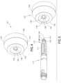
- the drug delivery pen 111 includes a lower housing 117 to which a hub 120 of the pen needle 113 is threadably connected, as shown in FIG. 5 .
- the pen needle 113 includes a needle 115 and a hub 120.
- a proximal end of the needle 115 is inserted into a center opening in the distal (patient) end of the hub 120 until a predetermined length of the distal (patient) end 116 of the needle 115 remains extended.
- the needle 115 is secured by epoxy or adhesive in the distal end of the hub 120 within the hub protrusion 118.
- a plurality of recesses 188 are formed in the outer surface of the hub 120, as shown in FIG. 5 .
- the pen needle removal device 121 includes a body 123, as shown in FIG. 4 .
- the body 123 includes an outer wall 131, an inwardly tapering wall 133, and an inner wall 135, as shown in FIG. 7 .
- the outer wall 131 extends upwardly from a free end 125 to an upper edge 132.
- the free end 125 of the outer wall 131 forms a base, thereby allowing the removal device 121 to sit flat on a surface to facilitate removing a pen needle 113 from the drug delivery device 111.
- the inwardly tapering wall 133 tapers inwardly from the upper edge 132 to an inner edge 134.
- the inner wall 135 extends toward the base from the inner edge 134.
- the inner wall 135 preferably has a first portion 136 having a first diameter and a second portion having a second diameter.
- the first portion 136 of the inner wall 135 extends from the inner edge 134.
- Inwardly extending ribs 181 can be formed on an inner surface of the first portion 136 of the inner wall, as shown in FIGS. 4 and 5 .
- An inwardly extending shoulder 139 is formed at the end of the first portion 136, and the second portion 138 extends toward the base from the shoulder 139.
- the first diameter is larger than the second diameter.
- a first opening 137 is formed in an end of the inner wall 135 to receive the ejector 151.
- the body 123 of the removal device 121 is unitarily formed as a single piece.
- the removal device 121 is shown having an inwardly tapering wall to form a concave configuration, the removal device may be configured to be convex or planar.
- the removal device 121 is made of plastic.
- a cavity 141 is formed in the body 123 and is defined by the inwardly tapering wall 133 and the inner wall 135.
- the cavity 141 accommodates a pen needle 113, as shown in FIG. 7 .
- the first portion 136 of the inner wall 135 accommodates the hub 120 of the pen needle, as shown in FIGS. 6 and 7 .
- an interference fit is formed between the first portion 136 of the inner wall 135 and the pen needle hub 120.
- the shoulder 139 is a stop to limit insertion of the drug delivery device 111 by engaging a surface of the pen needle hub 120.
- the hub protrusion 118 is received within the second portion 138 of the inner wall 135.
- the ejector 151 has a flange 153 and a wall 155 extending therefrom. Feet 157 extend outwardly from the free end of the wall 155. The ejector 151 extends through the opening 137, as shown in FIGS. 5 - 9 . The feet 157 prevent the ejector from being withdrawn past the shoulder 139 and the flange 153 prevents the ejector from being pushed through the first opening 137.
- a second opening 129 is formed in the free end 125 of the outer wall 131 to provide access to the ejector 151.
- the flange 153 facilitates selective manipulation of the ejector by the user.
- the drug delivery device is inserted in the cavity 141 of the removal device 121 until the base surface 122 of the pen needle hub 120 abuts the shoulder 139 of the removal device, as shown in FIG. 7 .
- the base of the removal device 121 can be placed on a table to facilitate insertion of the drug delivery device 111, thereby further preventing accidental needle sticks by not requiring the user to hold the removal device.
- the hub protrusion 118 and needle 115 are disposed within the wall 155 of the ejector 151.
- An interference fit is created between the pen needle hub 120 and the second portion 136 of the inner wall 135 of the removal device 121, thereby securely retaining the pen needle 113 within the removal device while the lower housing 117 of the drug delivery device 111 is rotated and unthreaded from the pen needle 113, as shown in FIG. 8 .
- the friction between the hub 120 of the pen needle 113 and the second portion 136 of the inner wall 135 of the removal device 121 prevents movement of the pen needle as the drug delivery device 111 is unthreaded from the removal device 121.
- the diameter of the second portion 136 is less than that of the pen needle hub 120 to create the interference fit therebetween.
- the pen needle 113 is securely retained within the removal device 121 with the patient end 116 of the needle 115 shielded within the wall 155 of the ejector 151 such that the user can carry the removal device 121 with the pen needle 113 disposed therein until the pen needle can be properly disposed of, such as in a sharps container.
- the ribs 181 formed on the second portion 136 of the inner wall 135 of the removal device 121 engage the recesses 188 formed in the pen needle hub 120. Accordingly, the ribs 181 prevent rotation of the pen needle hub 120 such that the drug delivery device 111 can be unthreaded from the removal device 121 while securely retaining the pen needle 113 in the removal device.
- the user pushes the ejector flange 153 inwardly in a direction substantially opposite to the insertion direction of the drug delivery device, as shown in FIG. 9 .
- the ejector 151 is moved in a direction substantially parallel to a longitudinal axis of the needle 115.
- the second portion 138 of the inner wall 135 guides movement of the ejector wall 155 during ejection of the pen needle 113.
- the feet 157 engage the base surface 122 of the hub 120, thereby overcoming the interference fit between the hub 120 and the second portion 136 of the inner wall 135 such that the pen needle 113 can be properly disposed of.
- the removal device comprises a cap 221.
- the drug delivery pen 221 includes a lower housing 217 to which a hub 220 of the pen needle 213 is threadably connected, as shown in FIG. 13 .
- the pen needle 213 includes a needle 215 and a hub 220. A proximal end of the needle 215 is inserted into a center opening in the distal (patient) end of the hub 220 until a predetermined length of the distal (patient) end 216 of the needle 215 remains extended.
- the needle 215 is secured by epoxy or adhesive in the distal end of the hub 220 within the hub protrusion 218.
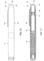
- the pen needle removal device, or cap, 221 as shown in FIGS. 10 - 17 , includes a body 223 having first and second openings 222 and 224 disposed at opposite ends thereof.
- the drug delivery device 211 is inserted through the second opening and the ejector 251 is inserted through the first opening 222.
- a flexible clip 226 is connected to the body 223 of the cap 221 to facilitate carrying the drug delivery device 211 by the user.
- An inwardly extending retaining ring 229 is disposed on an inner surface 228 of the body 223, as shown in FIGS. 11 and 13 - 15 .
- the retaining ring 229 preferably extends around an entire inner circumference of the cap body 223.
- a cavity 241 within the cap 221 is defined by the body 223 of the cap.
- the ejector 251 has a base 253 from which a wall 255 extends outwardly, as shown in FIGS. 11 - 15 .
- a tab 257 extends outwardly from the wall 255 proximate the base 253.
- the tab 257 which preferably extends around the entire circumference of the wall 255, engages an end 227 of the cap 221, as shown in FIGS. 10 and 11 , to limit movement of the ejector 251 into the cap 221.
- the ejector 251 can have a plurality of flexible fingers 271 disposed proximate an end 256 of the ejector wall 255, as shown in FIG. 16 and 17 .
- a tab 273 extends outwardly from each of the flexible fingers 271.
- Each tab 273 has a flat surface 274 that abuts an end 276 of a recess 275 formed in an inner surface 228 of the cap 221.
- the flexible fingers 271 flex inwardly to allow insertion of the ejector 251 into the cap 221.
- the engagement of the flat surface 274 of the flexible finger tab 271 with the end 276 of the recess 275 in the cap body 223 prevents complete withdrawal of the ejector 251 from the cap 221.
- the ejector 251 is movable between first and second positions. In a first position, as shown in FIGS. 10, 11 and 15 , the ejector 251 is pushed into the cap body 223 such that the ejector tab 257 abuts the end 227 of the cap 221. As shown in FIG. 11 , the cap wall 255 is received between the retaining ring 229 and the threaded portion of the lower housing 217. The end 256 of the ejector 251 also abuts the retaining ring 229. When the ejector is in the first position, it is an indication to the user that a pen needle is not connected to the drug delivery device 211.
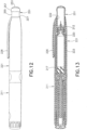
- the ejector 251 In the second position, the ejector 251 is partially withdrawn from the cap body 223, as shown in FIGS. 12 - 14 .
- the ejector 251 being in the second position is an indication to the user that a pen needle 213 is connected to the drug delivery device 211.
- the insertion of the pen needle 213 causes the base 212 of the hub 220 to partially push the ejector 251 out of the cap 221. Movement of the ejector 221 out of the cap 251 is limited by engagement of the flat surface 274 of the flexible finger tab 273 with the end 276 of the recess 275 in the cap body 223.
- a base surface 212 of the hub 220 engages the end 256 of the ejector wall 255 and moves the ejector from the first position ( FIG. 11 ) to the second position ( FIG. 12 ).
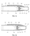
- the drug delivery device 211 is further inserted in the cap 221 until an interference fit is created between the outer surface of the hub wall 214 and the retaining ring 229, as shown in FIGS. 13 and 14 , thereby preventing further insertion of the drug delivery device.
- the drug delivery device 211 can then be rotated and unthreaded from the pen needle 213 such that the pen needle is securely retained in the cap 221, as shown in FIG. 14 .
- the patient end 216 of the needle 215 is covered by the ejector 251, thereby preventing accidental needle sticks.
- the user can carry the cap 221 with the pen needle 213 securely retained therein until the pen needle can be properly disposed of, such as in a sharps container.
- the retaining ring 229 can be formed as a plurality of ribs around the inner surface of the cap 221 that engage the recesses 188 ( FIG. 5 ) in the pen needle hub 220.
- the retaining ring ribs 229 engage the recesses in the pen needle hub 220, thereby preventing the pen needle 213 from rotating with the drug delivery device. Accordingly, the pen needle 213 is securely retained in the cap 221.
- the user pushes the base 253 of the ejector 251 inwardly in a direction substantially opposite to the insertion direction of the drug delivery device 211, as shown in FIG. 15 .
- the ejector 251 is moved in a direction substantially parallel to a longitudinal axis of the needle 215.
- the end 256 of the ejector wall 255 engages the base surface 212 of the hub 120, thereby overcoming the interference fit between the hub 220 and the retaining ring 229 of the cap 221 such that the pen needle 213 can be properly disposed of.
- the ejector tab 257 abuts the end 227 of the cap 221, thereby limiting insertion of the ejector 251 into the cap.
- the ejector cavity 261 which is defined by the base 253 and the wall 255, can accommodate an inner shield 59 ( FIG. 2 ) disposed on the hub protrusion 218.
- the user removes the cap 221 from the drug delivery device 211, thereby providing access to the pen needle 215. Pulling the cap overcomes the interference fit between the pen needle hub 220 and the retaining ring 229, such that the pen needle hub remains connected to the drug delivery device 211.
- the retaining ring ribs 229 do not engage the walls of the pen needle hub 220 so that the drug delivery device can be pulled outwardly from the cap 221 with the pen needle 213 connected to the drug delivery device.
- the inner shield 59 is then removed from the pen needle hub 220 so that the injection can be made.
- the used pen needle is then reinserted into the cap 221, as described above, such that the ejector 251 moves to the second position, as shown in FIG. 12 , thereby indicating the presence of a pen needle.
- the used pen needle can then be properly disposed of as described above.
Landscapes
- Health & Medical Sciences (AREA)
- Engineering & Computer Science (AREA)
- Hematology (AREA)
- Anesthesiology (AREA)
- Biomedical Technology (AREA)
- Heart & Thoracic Surgery (AREA)
- Vascular Medicine (AREA)
- Life Sciences & Earth Sciences (AREA)
- Animal Behavior & Ethology (AREA)
- General Health & Medical Sciences (AREA)
- Public Health (AREA)
- Veterinary Medicine (AREA)
- Environmental & Geological Engineering (AREA)
- Infusion, Injection, And Reservoir Apparatuses (AREA)
- Accommodation For Nursing Or Treatment Tables (AREA)
Claims (9)
- Entfernungsvorrichtung zum Entfernen und Entsorgen einer Pen-Nadel (213), die mit einer Arzneimittelabgabevorrichtung (211) verbindbar ist, wobei die Vorrichtung aufweist:eine Kappe (221), die einen Körper (223) mit einem Hohlraum (241) zur Aufnahme der Pen-Nadel (213) der Arzneimittelabgabevorrichtung (211) aufweist, so dass ein Patientenende (216) einer Nadel (215) der Pen-Nadel (213) von dem Körper (223) bedeckt wird;eine erste und eine zweite Öffnung (222, 224), die an entgegengesetzten Enden des Körpers (223) angeordnet und entfernbar mit der Arzneimittelabgabevorrichtung (211) verbindbar sind, die durch die zweite Öffnung (224) eingesetzt wird; undeinen Ejektor (251), der über die erste Öffnung (222) bewegbar mit dem Körper (223) verbunden ist, wobei der Ejektor (251) einen Ejektorhohlraum (261) zum Eingreifen der aufgenommenen Pen-Nadel (213) und zum wahlweise Auswerfen der eingegriffenen Pen-Nadel (213) aus dem Körper (223) aufweist,wobeider Ejektor (251) sich in einer teilweise aus dem Kappenkörper (223) zurückgezogenen Position befindet, wenn die Kappe (221) mit der Arzneimittelabgabevorrichtung (211) verbunden ist, mit der die Pen-Nadel (213) verbunden ist, als einen Hinweis darauf, dass die Pen-Nadel (213) mit der Arzneimittelabgabevorrichtung (211) verbunden ist, undder Ejektor (251) sich in einer eingesetzten Position befindet, wenn die Kappe (221) mit der Arzneimittelabgabevorrichtung (211) verbunden ist, mit der die Pen-Nadel (213) nicht verbunden ist, als einen Hinweis darauf, dass die Pen-Nadel (213) nicht mit der Arzneimittelabgabevorrichtung (211) verbunden ist.
- Entfernungsvorrichtung nach Anspruch 1, wobei das Bewegen des Ejektors (251) in den Körper (223) bewirkt, dass die in Eingriff mit dem Ejektor (251) befindliche Pen-Nadel (213) aus dem Körper (223) ausgeworfen wird.
- Entfernungsvorrichtung nach Anspruch 1, wobeider Ejektor (251) eine Basis (253) und eine Ejektorwand (255) aufweist, die sich ausgehend von der Ejektorbasis (253) erstreckt, undder Ejektorhohlraum (261) durch die Basis (253) und die Wand (255) definiert wird.
- Entfernungsvorrichtung nach Anspruch 1, wobei
ein Abschnitt (229) einer Innenfläche des Körpers (223), der den Hohlraum (241) aufweist, eine Vielzahl von sich nach innen erstreckenden Rippen aufweist, die so ausgebildet sind, dass sie in Aussparrungen in dem Ansatz der Pen-Nadel (213) eingreifen. - Entfernungsvorrichtung nach Anspruch 3, wobeider Hohlraum (241) so in der Kappe (221) angeordnet ist, dass die Kappe (221) wahlweise von der Arzneimittelabgabevorrichtung (211) entfernbar ist, wobei die Pen-Nadel (213) in der Kappe (221) zurückgehalten wird; undder Hohlraum (241) in der Kappe (221) relativ zur ersten Öffnung (222) angeordnet ist, so dass die Bewegung des Ejektors (251) in die Kappe (221) bewirkt, dass ein Ende (256) des Ejektors (251) in den Ansatz der Pen-Nadel (213) eingreift, um die Pen-Nadel (213) wahlweise von der Kappe (221) abzuwerfen.
- Entfernungsvorrichtung nach Anspruch 1, wobei der Ejektor (251) eine Lasche (257) aufweist, die sich ausgehend von dem Ejektor (251) nach außen erstreckt, um die Bewegung des Ejektors (251) in die Kappe (221) zu begrenzen.
- Entfernungsvorrichtung nach Anspruch 1, wobei der Ejektor (251) eine Lasche (273) aufweist, die sich ausgehend von dem Ejektor (251) nach außen erstreckt, um ein vollständiges Zurückziehen des Ejektors (251) aus der Kappe (221) zu verhindern.
- Verfahren zum Entfernen einer Pen-Nadel (213) von einer Arzneimittelabgabevorrichtung (211), die eine Kappe (211) aufweist, die entfernbar mit der Arzneimittelabgabevorrichtung (211) verbunden ist,wobei die Kappe (211) einen Körper (223) mit einem Hohlraum (241) zur Aufnahme der Pen-Nadel (213) der Arzneimittelabgabevorrichtung (211) aufweist, so dass ein Patientenende (216) der Nadel (215) der Pen-Nadel (213) von dem Körper (223) bedeckt wird;wobei eine erste und eine zweite Öffnung (222, 224) an entgegengesetzten Enden des Körpers (223) angeordnet und entfernbar mit der Arzneimittelabgabevorrichtung (211) verbindbar sind, die durch die zweite Öffnung (224) eingesetzt wird; undwobei ein Ejektor (251) über die erste Öffnung (222) bewegbar mit dem Körper (223) verbunden ist, wobei der Ejektor (251) einen Ejektorhohlraum (261) zum Eingreifen der aufgenommenen Pen-Nadel (213) und zum wahlweise Auswerfen der eingegriffenen Pen-Nadel (213) aus dem Körper (223) aufweist,wobei das Verfahren die folgenden Schritte umfasst:Bereitstellen eines Hinweises dafür, dass die Pen-Nadel (213) mit der Arzneimittelabgabevorrichtung (211) verbunden ist, indem sich der Ejektor (251) in einer teilweise zurückgezogenen Position befindet, wenn die Kappe (221) mit der Arzneimittelabgabevorrichtung (211) verbunden ist, mit der die Pen-Nadel (213) verbunden ist,Bereitstellen eines Hinweises dafür, dass die Pen-Nadel (213) nicht mit der Arzneimittelabgabevorrichtung (211) verbunden ist, indem sich der Ejektor (251) in einer eingesetzten Position befindet, wenn die Kappe (221) nicht mit der Arzneimittelabgabevorrichtung (211) verbunden ist, mit der die Pen-Nadel (213) verbunden ist,Einsetzen der Pen-Nadel (213) der Arzneimittelabgabevorrichtung (211) in den Hohlraum (241) des Körpers (223) der Kappe (221), so dass das Patientenende (216) der Nadel (215) der Pen-Nadel (213) von dem Körper (223) bedeckt wird;in Eingriff bringen der eingesetzten Pen-Nadel (213) mit dem Körper (223); Entfernen der Arzneimittelabgabevorrichtung (211) von dem Körper (223) der Kappe (221), so dass die sich in Eingriff befindliche Pen-Nadel (213) von dem Körper (223) zurückgehalten wird; undAuswerfen der Pen-Nadel (213) aus dem Körper (223) mit dem Ejektor (251).
- Verfahren nach Anspruch 8, wobeider Schritt des Einsetzens das Einsetzen der Pen-Nadel (213) der Arzneimittelabgabevorrichtung (211) durch die zweite Öffnung (224) umfasst, so dass der Körper (223) in einen Ansatz (220) der Pen-Nadel (213) eingreift und der Ansatz (220) den Ejektor (251) von der eingesetzten Position in die zurückgezogene Position bewegt, undder Schritt des Auswerfens das Bewegen des Ejektors (251) in die Kappe (221) aus der zurückgezogenen Position in Richtung der eingesetzten Position umfasst, um den Ansatz (220) der Pen-Nadel (213) von dem Körper (223) zu lösen.
Applications Claiming Priority (3)
| Application Number | Priority Date | Filing Date | Title |
|---|---|---|---|
| US26662309P | 2009-12-04 | 2009-12-04 | |
| EP10834872.3A EP2506897B1 (de) | 2009-12-04 | 2010-12-03 | Vorrichtung zur entfernung einer stiftnadel für eine wirkstoffabgabevorrichtung |
| PCT/US2010/003086 WO2011068543A1 (en) | 2009-12-04 | 2010-12-03 | Pen needle removal device for a drug delivery device |
Related Parent Applications (1)
| Application Number | Title | Priority Date | Filing Date |
|---|---|---|---|
| EP10834872.3A Division EP2506897B1 (de) | 2009-12-04 | 2010-12-03 | Vorrichtung zur entfernung einer stiftnadel für eine wirkstoffabgabevorrichtung |
Publications (3)
| Publication Number | Publication Date |
|---|---|
| EP4233945A1 EP4233945A1 (de) | 2023-08-30 |
| EP4233945C0 EP4233945C0 (de) | 2025-06-04 |
| EP4233945B1 true EP4233945B1 (de) | 2025-06-04 |
Family
ID=44115214
Family Applications (2)
| Application Number | Title | Priority Date | Filing Date |
|---|---|---|---|
| EP10834872.3A Active EP2506897B1 (de) | 2009-12-04 | 2010-12-03 | Vorrichtung zur entfernung einer stiftnadel für eine wirkstoffabgabevorrichtung |
| EP23170584.9A Active EP4233945B1 (de) | 2009-12-04 | 2010-12-03 | Stiftnadelentfernungsvorrichtung für eine arzneimittelabgabevorrichtung |
Family Applications Before (1)
| Application Number | Title | Priority Date | Filing Date |
|---|---|---|---|
| EP10834872.3A Active EP2506897B1 (de) | 2009-12-04 | 2010-12-03 | Vorrichtung zur entfernung einer stiftnadel für eine wirkstoffabgabevorrichtung |
Country Status (7)
| Country | Link |
|---|---|
| US (5) | US8882706B2 (de) |
| EP (2) | EP2506897B1 (de) |
| JP (1) | JP6105288B2 (de) |
| CN (2) | CN102711872B (de) |
| ES (1) | ES2952384T3 (de) |
| IN (1) | IN2012DN04942A (de) |
| WO (1) | WO2011068543A1 (de) |
Families Citing this family (17)
| Publication number | Priority date | Publication date | Assignee | Title |
|---|---|---|---|---|
| US20110023281A1 (en) * | 2009-04-30 | 2011-02-03 | Stat Medical Devices, Inc. | Pen injection device cap with integral pen needle quick release and/or removal system |
| WO2011068543A1 (en) * | 2009-12-04 | 2011-06-09 | Becton, Dickinson And Company | Pen needle removal device for a drug delivery device |
| JP5946461B2 (ja) * | 2010-10-12 | 2016-07-06 | サノフィ−アベンティス・ドイチュラント・ゲゼルシャフト・ミット・ベシュレンクテル・ハフツング | 薬物送達デバイスのためのキャップ・アセンブリ |
| USD752211S1 (en) * | 2012-08-01 | 2016-03-22 | Sanofi-Aventis Deutschland Gmbh | Injection device |
| USD752738S1 (en) * | 2013-09-20 | 2016-03-29 | Sanofi-Aventis Deutschland Gmbh | Injection device |
| USD777317S1 (en) * | 2013-12-16 | 2017-01-24 | Ed-Liq | Cannula and cap |
| USD743538S1 (en) * | 2014-01-17 | 2015-11-17 | Sanofi-Aventis Deutschland Gmbh | Injection device |
| USD777908S1 (en) * | 2014-08-27 | 2017-01-31 | Merck Sharp & Dohme Corp. | Medical injector pen |
| USD752210S1 (en) * | 2014-08-27 | 2016-03-22 | Merck Sharp & Dohme Corp. | Medical injector pen |
| CA2895103A1 (en) | 2015-06-25 | 2016-12-25 | Montmed Inc | Coloured pen needles, kit and method for using the same |
| KR102209807B1 (ko) * | 2015-12-08 | 2021-01-29 | 벡톤 디킨슨 프랑스 | 의료용 주입기용 반구형 부분을 구비한 캡 |
| CN108144159B (zh) * | 2016-12-06 | 2021-09-10 | 贝克顿·迪金森公司 | 用于安装笔式针组件的装置 |
| CA3044117A1 (en) | 2016-12-06 | 2018-06-14 | Becton, Dickinson And Company | Apparatus for mounting a pen needle assembly |
| WO2019010017A1 (en) | 2017-07-07 | 2019-01-10 | Becton, Dickinson And Company | MEDICAL DEVICE FOR REMOVING AND STORING MEDICAL DEVICES |
| JP1631211S (de) * | 2017-11-06 | 2019-05-13 | ||
| CN108853634B (zh) * | 2018-04-02 | 2024-04-09 | 宁波卫生职业技术学院 | 带锐器盒的注射盘 |
| CN119950899B (zh) * | 2025-02-21 | 2025-08-22 | 江苏万海医疗器械有限公司 | 自清式笔盖、笔式注射器及笔式注射器的工作方法 |
Family Cites Families (47)
| Publication number | Priority date | Publication date | Assignee | Title |
|---|---|---|---|---|
| US5312346A (en) | 1993-02-16 | 1994-05-17 | Han Medical Designs, Inc. | Needle removing device |
| ATE211398T1 (de) | 1994-02-28 | 2002-01-15 | Novo Nordisk As | Nadeleinheit |
| US5829589A (en) * | 1997-09-12 | 1998-11-03 | Becton Dickinson And Company | Pen needle magazine dispenser |
| CN1212165C (zh) | 2000-05-15 | 2005-07-27 | 阿雷斯贸易股份有限公司 | 至少能存放一根皮下注射针头的针头存放容器 |
| MXPA02010687A (es) | 2000-05-15 | 2004-07-30 | Ares Trading Sa | Dispositivo para separar el extremo de conexion de aguja hipodermica, de la punta de un instrumento de inyeccion. |
| TWI290925B (en) * | 2000-11-20 | 2007-12-11 | Sankyo Co | Production of carbapenem antimicrobial agent |
| US20020068908A1 (en) | 2000-12-01 | 2002-06-06 | Wu-Chung Sun | Cap for a syringe |
| GB0124297D0 (en) | 2001-10-10 | 2001-11-28 | Owen Mumford Ltd | Improvements relating to injection devices |
| US7021463B2 (en) | 2002-09-06 | 2006-04-04 | Becton, Dickinson And Company | Pen needle sharps port |
| DE10255134A1 (de) | 2002-11-26 | 2004-06-09 | Tecpharma Licensing Ag | Abziehvorrichtung für Injektionsnadeln |
| DE10327119A1 (de) | 2003-06-13 | 2004-12-30 | Aventis Pharma Deutschland Gmbh | Kappe für Injektionsvorrichtungen |
| CA2551698C (en) | 2004-01-07 | 2016-05-24 | Smiths Medical Asd, Inc. | Needle protection device with gauge specific color coding and method for manufacturing thereof |
| GB0403335D0 (en) * | 2004-02-14 | 2004-03-17 | Liversidge Barry P | Medical injector handling device |
| GB0409354D0 (en) | 2004-04-27 | 2004-06-02 | Owen Mumford Ltd | Removal of needles |
| US6923319B1 (en) * | 2004-06-07 | 2005-08-02 | Ulti Med Inc. | Sharps container for safe transportation and dispensing of unused pen needle assemblies and for sequential safe storage of used pen needles |
| US6923318B1 (en) * | 2004-06-07 | 2005-08-02 | Ulti Med, Inc | Sharps container for safe storage of used pen needles and used medical syringes |
| US7344027B2 (en) * | 2004-06-07 | 2008-03-18 | Ultimed, Inc. | Sharps container for “no-touch,” sequential safe storage of used pen needles |
| US7465264B2 (en) | 2004-07-12 | 2008-12-16 | Rohm And Haas Denmark Finance A/S | Axially compliant pressure roller utilizing non-newtonian fluid |
| US20060100588A1 (en) * | 2004-07-23 | 2006-05-11 | Lennart Brunnberg | Needle handling device |
| DK1830907T3 (da) | 2004-09-24 | 2009-08-10 | Sanofi Aventis Deutschland | Hætte til lægemiddelfrigivelsesanordninger |
| GB0427507D0 (en) | 2004-12-16 | 2005-01-19 | Frontier Plastics Ltd | Improvements relating to injection syringes and needles |
| US7645264B2 (en) | 2005-04-11 | 2010-01-12 | Becton, Dickinson And Company | Injection device with secondary reservoir |
| JP5030963B2 (ja) | 2005-10-13 | 2012-09-19 | ベクトン・ディキンソン・アンド・カンパニー | 使い捨ての針及びハブの組立体 |
| DE102005054075A1 (de) | 2005-11-12 | 2007-05-16 | Vetter & Co Apotheker | Kanülenaufsatz für eine Spritze oder Karpule |
| DE102005061637A1 (de) * | 2005-12-22 | 2007-07-05 | Tecpharma Licensing Ag | Nadelträgerentfernungsvorrichtung zum Entfernen eines Nadelträgers von einem Injektionsgerät |
| US7780637B2 (en) * | 2006-11-06 | 2010-08-24 | Steven Jerde | Medical device container |
| WO2008067467A2 (en) | 2006-11-29 | 2008-06-05 | West Pharmaceutical Services, Inc. | Syringe cartridge system |
| US7871397B2 (en) | 2006-12-26 | 2011-01-18 | Stat Medical Devices, Inc. | Pen needle tip |
| DE102007022404A1 (de) | 2007-05-10 | 2008-11-13 | B. Braun Melsungen Ag | Vorrichtung zum Halten einer Kanüle und zur lösbaren Anordnung an einer Einrichtung zur Injektion von Flüssigkeiten |
| US20090014462A1 (en) * | 2007-07-10 | 2009-01-15 | Pharmadesign, Inc. | Needle dispenser system and hand tool for same |
| US20090236347A1 (en) * | 2008-03-19 | 2009-09-24 | Ultimed Inc. | Sharps container |
| EP2201976A1 (de) | 2008-12-23 | 2010-06-30 | Sanofi-Aventis Deutschland GmbH | Vorrichtung zum Halten eines Deckels einer Nadeleinheit und Verfahren |
| GB0900930D0 (en) | 2009-01-20 | 2009-03-04 | Future Injection Technologies Ltd | Injection device |
| JP2012110356A (ja) | 2009-03-31 | 2012-06-14 | Mikuni Kogyo:Kk | 廃棄針用回収容器及び廃棄針用回収部品 |
| WO2010122683A1 (ja) | 2009-04-24 | 2010-10-28 | 株式会社ファインプロ | 注射針廃棄用容器 |
| US20110023281A1 (en) * | 2009-04-30 | 2011-02-03 | Stat Medical Devices, Inc. | Pen injection device cap with integral pen needle quick release and/or removal system |
| WO2010142813A1 (en) | 2009-06-12 | 2010-12-16 | Novo Nordisk A/S | Drug delivery device with cap functions for needle assembly |
| EP2464400B1 (de) | 2009-08-12 | 2015-01-28 | Sanofi-Aventis Deutschland GmbH | Kappe für eine tragbare medizinische Abgabevorrichtung und eine derartige medizinische Abgabevorrichtung |
| EP2298390A1 (de) | 2009-08-28 | 2011-03-23 | Sanofi-Aventis Deutschland GmbH | Medizinische Abgabevorrichtung, Gehäusekappe für eine medizinische Abgabevorrichtung und Antriebsmechanismus für eine medizinische Abgabevorrichtung |
| BR112012006268A2 (pt) | 2009-09-21 | 2017-05-23 | Novo Nordisk As | sistema de envio de fármaco e dispositivo com função de tampa |
| JP2011136153A (ja) | 2009-10-19 | 2011-07-14 | Terumo Medical Corp | 注射器組立体を備えているキット |
| WO2011068130A1 (ja) | 2009-12-02 | 2011-06-09 | テルモ株式会社 | プレフィルドシリンジ |
| WO2011068131A1 (ja) | 2009-12-02 | 2011-06-09 | テルモ株式会社 | プレフィルドシリンジ |
| WO2011068543A1 (en) * | 2009-12-04 | 2011-06-09 | Becton, Dickinson And Company | Pen needle removal device for a drug delivery device |
| CN102481230A (zh) | 2010-03-05 | 2012-05-30 | 泰尔茂株式会社 | 医疗器具 |
| JP5928824B2 (ja) | 2010-03-18 | 2016-06-01 | 株式会社大協精工 | シリンジニードルキャップ |
| WO2011125475A1 (ja) | 2010-03-31 | 2011-10-13 | テルモ株式会社 | シリンジ |
-
2010
- 2010-12-03 WO PCT/US2010/003086 patent/WO2011068543A1/en not_active Ceased
- 2010-12-03 CN CN201080061120.2A patent/CN102711872B/zh active Active
- 2010-12-03 EP EP10834872.3A patent/EP2506897B1/de active Active
- 2010-12-03 US US13/513,159 patent/US8882706B2/en active Active
- 2010-12-03 CN CN201510095575.0A patent/CN104689429B/zh active Active
- 2010-12-03 EP EP23170584.9A patent/EP4233945B1/de active Active
- 2010-12-03 JP JP2012541994A patent/JP6105288B2/ja active Active
- 2010-12-03 ES ES10834872T patent/ES2952384T3/es active Active
-
2012
- 2012-06-05 IN IN4942DEN2012 patent/IN2012DN04942A/en unknown
-
2014
- 2014-10-17 US US14/517,395 patent/US9861760B2/en active Active
-
2018
- 2018-01-05 US US15/863,655 patent/US10744273B2/en active Active
-
2020
- 2020-08-13 US US16/993,163 patent/US11786670B2/en active Active
-
2023
- 2023-10-16 US US18/487,655 patent/US12569626B2/en active Active
Also Published As
| Publication number | Publication date |
|---|---|
| US20120302965A1 (en) | 2012-11-29 |
| WO2011068543A1 (en) | 2011-06-09 |
| ES2952384T3 (es) | 2023-10-31 |
| US10744273B2 (en) | 2020-08-18 |
| US20180126092A1 (en) | 2018-05-10 |
| US20240277945A1 (en) | 2024-08-22 |
| CN104689429A (zh) | 2015-06-10 |
| EP2506897A4 (de) | 2015-02-25 |
| US20150033535A1 (en) | 2015-02-05 |
| CN102711872B (zh) | 2015-02-25 |
| US11786670B2 (en) | 2023-10-17 |
| EP2506897B1 (de) | 2023-05-31 |
| CN102711872A (zh) | 2012-10-03 |
| EP4233945C0 (de) | 2025-06-04 |
| IN2012DN04942A (de) | 2015-09-25 |
| EP2506897A1 (de) | 2012-10-10 |
| US20200368450A1 (en) | 2020-11-26 |
| US8882706B2 (en) | 2014-11-11 |
| JP6105288B2 (ja) | 2017-03-29 |
| US12569626B2 (en) | 2026-03-10 |
| JP2013512727A (ja) | 2013-04-18 |
| US9861760B2 (en) | 2018-01-09 |
| EP4233945A1 (de) | 2023-08-30 |
| CN104689429B (zh) | 2018-03-06 |
Similar Documents
| Publication | Publication Date | Title |
|---|---|---|
| US12569626B2 (en) | Pen needle removal device for a drug delivery device | |
| US10799650B2 (en) | Disposable pen needle with re-use prevention features | |
| EP2393531B1 (de) | Stiftnadel zur vereinfachten handhabung durch benutzer mit physischen oder visuellen beeinträchtigungen | |
| US11602600B2 (en) | Apparatus for mounting a pen needle assembly |
Legal Events
| Date | Code | Title | Description |
|---|---|---|---|
| PUAI | Public reference made under article 153(3) epc to a published international application that has entered the european phase |
Free format text: ORIGINAL CODE: 0009012 |
|
| STAA | Information on the status of an ep patent application or granted ep patent |
Free format text: STATUS: THE APPLICATION HAS BEEN PUBLISHED |
|
| AC | Divisional application: reference to earlier application |
Ref document number: 2506897 Country of ref document: EP Kind code of ref document: P |
|
| AK | Designated contracting states |
Kind code of ref document: A1 Designated state(s): AL AT BE BG CH CY CZ DE DK EE ES FI FR GB GR HR HU IE IS IT LI LT LU LV MC MK MT NL NO PL PT RO RS SE SI SK SM TR |
|
| STAA | Information on the status of an ep patent application or granted ep patent |
Free format text: STATUS: REQUEST FOR EXAMINATION WAS MADE |
|
| 17P | Request for examination filed |
Effective date: 20240227 |
|
| RBV | Designated contracting states (corrected) |
Designated state(s): AL AT BE BG CH CY CZ DE DK EE ES FI FR GB GR HR HU IE IS IT LI LT LU LV MC MK MT NL NO PL PT RO RS SE SI SK SM TR |
|
| RIN1 | Information on inventor provided before grant (corrected) |
Inventor name: CRONENBERG, RICHARD |
|
| RIC1 | Information provided on ipc code assigned before grant |
Ipc: A61M 5/315 20060101ALN20241121BHEP Ipc: A61M 5/24 20060101ALN20241121BHEP Ipc: A61M 5/32 20060101AFI20241121BHEP |
|
| GRAP | Despatch of communication of intention to grant a patent |
Free format text: ORIGINAL CODE: EPIDOSNIGR1 |
|
| STAA | Information on the status of an ep patent application or granted ep patent |
Free format text: STATUS: GRANT OF PATENT IS INTENDED |
|
| INTG | Intention to grant announced |
Effective date: 20250102 |
|
| GRAS | Grant fee paid |
Free format text: ORIGINAL CODE: EPIDOSNIGR3 |
|
| GRAA | (expected) grant |
Free format text: ORIGINAL CODE: 0009210 |
|
| STAA | Information on the status of an ep patent application or granted ep patent |
Free format text: STATUS: THE PATENT HAS BEEN GRANTED |
|
| AC | Divisional application: reference to earlier application |
Ref document number: 2506897 Country of ref document: EP Kind code of ref document: P |
|
| AK | Designated contracting states |
Kind code of ref document: B1 Designated state(s): AL AT BE BG CH CY CZ DE DK EE ES FI FR GB GR HR HU IE IS IT LI LT LU LV MC MK MT NL NO PL PT RO RS SE SI SK SM TR |
|
| REG | Reference to a national code |
Ref country code: GB Ref legal event code: FG4D |
|
| REG | Reference to a national code |
Ref country code: CH Ref legal event code: EP |
|
| REG | Reference to a national code |
Ref country code: DE Ref legal event code: R096 Ref document number: 602010069775 Country of ref document: DE |
|
| REG | Reference to a national code |
Ref country code: IE Ref legal event code: FG4D |
|
| U01 | Request for unitary effect filed |
Effective date: 20250703 |
|
| U07 | Unitary effect registered |
Designated state(s): AT BE BG DE DK EE FI FR IT LT LU LV MT NL PT RO SE SI Effective date: 20250710 |
|
| PG25 | Lapsed in a contracting state [announced via postgrant information from national office to epo] |
Ref country code: ES Free format text: LAPSE BECAUSE OF FAILURE TO SUBMIT A TRANSLATION OF THE DESCRIPTION OR TO PAY THE FEE WITHIN THE PRESCRIBED TIME-LIMIT Effective date: 20250604 |
|
| PG25 | Lapsed in a contracting state [announced via postgrant information from national office to epo] |
Ref country code: NO Free format text: LAPSE BECAUSE OF FAILURE TO SUBMIT A TRANSLATION OF THE DESCRIPTION OR TO PAY THE FEE WITHIN THE PRESCRIBED TIME-LIMIT Effective date: 20250904 Ref country code: GR Free format text: LAPSE BECAUSE OF FAILURE TO SUBMIT A TRANSLATION OF THE DESCRIPTION OR TO PAY THE FEE WITHIN THE PRESCRIBED TIME-LIMIT Effective date: 20250905 |
|
| PG25 | Lapsed in a contracting state [announced via postgrant information from national office to epo] |
Ref country code: PL Free format text: LAPSE BECAUSE OF FAILURE TO SUBMIT A TRANSLATION OF THE DESCRIPTION OR TO PAY THE FEE WITHIN THE PRESCRIBED TIME-LIMIT Effective date: 20250604 |
|
| PG25 | Lapsed in a contracting state [announced via postgrant information from national office to epo] |
Ref country code: HR Free format text: LAPSE BECAUSE OF FAILURE TO SUBMIT A TRANSLATION OF THE DESCRIPTION OR TO PAY THE FEE WITHIN THE PRESCRIBED TIME-LIMIT Effective date: 20250604 |
|
| PG25 | Lapsed in a contracting state [announced via postgrant information from national office to epo] |
Ref country code: RS Free format text: LAPSE BECAUSE OF FAILURE TO SUBMIT A TRANSLATION OF THE DESCRIPTION OR TO PAY THE FEE WITHIN THE PRESCRIBED TIME-LIMIT Effective date: 20250904 |
|
| U20 | Renewal fee for the european patent with unitary effect paid |
Year of fee payment: 16 Effective date: 20251119 |
|
| PG25 | Lapsed in a contracting state [announced via postgrant information from national office to epo] |
Ref country code: IS Free format text: LAPSE BECAUSE OF FAILURE TO SUBMIT A TRANSLATION OF THE DESCRIPTION OR TO PAY THE FEE WITHIN THE PRESCRIBED TIME-LIMIT Effective date: 20251004 |
|
| PGFP | Annual fee paid to national office [announced via postgrant information from national office to epo] |
Ref country code: GB Payment date: 20251120 Year of fee payment: 16 |
|
| PG25 | Lapsed in a contracting state [announced via postgrant information from national office to epo] |
Ref country code: SM Free format text: LAPSE BECAUSE OF FAILURE TO SUBMIT A TRANSLATION OF THE DESCRIPTION OR TO PAY THE FEE WITHIN THE PRESCRIBED TIME-LIMIT Effective date: 20250604 |
|
| PG25 | Lapsed in a contracting state [announced via postgrant information from national office to epo] |
Ref country code: CZ Free format text: LAPSE BECAUSE OF FAILURE TO SUBMIT A TRANSLATION OF THE DESCRIPTION OR TO PAY THE FEE WITHIN THE PRESCRIBED TIME-LIMIT Effective date: 20250604 |
|
| PG25 | Lapsed in a contracting state [announced via postgrant information from national office to epo] |
Ref country code: SK Free format text: LAPSE BECAUSE OF FAILURE TO SUBMIT A TRANSLATION OF THE DESCRIPTION OR TO PAY THE FEE WITHIN THE PRESCRIBED TIME-LIMIT Effective date: 20250604 |
|
| PLBE | No opposition filed within time limit |
Free format text: ORIGINAL CODE: 0009261 |
|
| STAA | Information on the status of an ep patent application or granted ep patent |
Free format text: STATUS: NO OPPOSITION FILED WITHIN TIME LIMIT |
|
| REG | Reference to a national code |
Ref country code: CH Ref legal event code: L10 Free format text: ST27 STATUS EVENT CODE: U-0-0-L10-L00 (AS PROVIDED BY THE NATIONAL OFFICE) Effective date: 20260416 |