EP4233796A2 - Valve prosthétique unicuspide présentant un sinus partiel - Google Patents
Valve prosthétique unicuspide présentant un sinus partiel Download PDFInfo
- Publication number
- EP4233796A2 EP4233796A2 EP23176215.4A EP23176215A EP4233796A2 EP 4233796 A2 EP4233796 A2 EP 4233796A2 EP 23176215 A EP23176215 A EP 23176215A EP 4233796 A2 EP4233796 A2 EP 4233796A2
- Authority
- EP
- European Patent Office
- Prior art keywords
- valve
- prosthesis
- frame
- leaflet
- interior lumen
- Prior art date
- Legal status (The legal status is an assumption and is not a legal conclusion. Google has not performed a legal analysis and makes no representation as to the accuracy of the status listed.)
- Pending
Links
- 230000036961 partial effect Effects 0.000 title claims abstract description 74
- 239000000463 material Substances 0.000 claims description 79
- 239000012530 fluid Substances 0.000 claims description 65
- 210000001519 tissue Anatomy 0.000 claims description 65
- 102000010834 Extracellular Matrix Proteins Human genes 0.000 claims description 18
- 108010037362 Extracellular Matrix Proteins Proteins 0.000 claims description 18
- 210000002744 extracellular matrix Anatomy 0.000 claims description 18
- RTAQQCXQSZGOHL-UHFFFAOYSA-N Titanium Chemical compound [Ti] RTAQQCXQSZGOHL-UHFFFAOYSA-N 0.000 claims description 8
- 239000010941 cobalt Substances 0.000 claims description 8
- GUTLYIVDDKVIGB-UHFFFAOYSA-N cobalt atom Chemical compound [Co] GUTLYIVDDKVIGB-UHFFFAOYSA-N 0.000 claims description 8
- BASFCYQUMIYNBI-UHFFFAOYSA-N platinum Chemical compound [Pt] BASFCYQUMIYNBI-UHFFFAOYSA-N 0.000 claims description 8
- 229910052719 titanium Inorganic materials 0.000 claims description 8
- 239000010936 titanium Substances 0.000 claims description 8
- 230000033001 locomotion Effects 0.000 claims description 7
- 229910001000 nickel titanium Inorganic materials 0.000 claims description 7
- 229910001220 stainless steel Inorganic materials 0.000 claims description 7
- 239000010935 stainless steel Substances 0.000 claims description 7
- FYYHWMGAXLPEAU-UHFFFAOYSA-N Magnesium Chemical compound [Mg] FYYHWMGAXLPEAU-UHFFFAOYSA-N 0.000 claims description 6
- PXHVJJICTQNCMI-UHFFFAOYSA-N Nickel Chemical compound [Ni] PXHVJJICTQNCMI-UHFFFAOYSA-N 0.000 claims description 6
- 229910052749 magnesium Inorganic materials 0.000 claims description 6
- 239000011777 magnesium Substances 0.000 claims description 6
- 239000011159 matrix material Substances 0.000 claims description 6
- 229910000531 Co alloy Inorganic materials 0.000 claims description 5
- 229910000599 Cr alloy Inorganic materials 0.000 claims description 5
- 239000000788 chromium alloy Substances 0.000 claims description 5
- PCHJSUWPFVWCPO-UHFFFAOYSA-N gold Chemical compound [Au] PCHJSUWPFVWCPO-UHFFFAOYSA-N 0.000 claims description 5
- 229910052737 gold Inorganic materials 0.000 claims description 5
- 239000010931 gold Substances 0.000 claims description 5
- 229910052715 tantalum Inorganic materials 0.000 claims description 5
- GUVRBAGPIYLISA-UHFFFAOYSA-N tantalum atom Chemical compound [Ta] GUVRBAGPIYLISA-UHFFFAOYSA-N 0.000 claims description 5
- 239000002131 composite material Substances 0.000 claims description 4
- HLXZNVUGXRDIFK-UHFFFAOYSA-N nickel titanium Chemical compound [Ti].[Ti].[Ti].[Ti].[Ti].[Ti].[Ti].[Ti].[Ti].[Ti].[Ti].[Ni].[Ni].[Ni].[Ni].[Ni].[Ni].[Ni].[Ni].[Ni].[Ni].[Ni].[Ni].[Ni].[Ni] HLXZNVUGXRDIFK-UHFFFAOYSA-N 0.000 claims description 4
- 229910052758 niobium Inorganic materials 0.000 claims description 4
- 239000010955 niobium Substances 0.000 claims description 4
- GUCVJGMIXFAOAE-UHFFFAOYSA-N niobium atom Chemical compound [Nb] GUCVJGMIXFAOAE-UHFFFAOYSA-N 0.000 claims description 4
- 229910052697 platinum Inorganic materials 0.000 claims description 4
- WFKWXMTUELFFGS-UHFFFAOYSA-N tungsten Chemical compound [W] WFKWXMTUELFFGS-UHFFFAOYSA-N 0.000 claims description 4
- 229910052721 tungsten Inorganic materials 0.000 claims description 4
- 239000010937 tungsten Substances 0.000 claims description 4
- VYZAMTAEIAYCRO-UHFFFAOYSA-N Chromium Chemical compound [Cr] VYZAMTAEIAYCRO-UHFFFAOYSA-N 0.000 claims description 3
- 229910052782 aluminium Inorganic materials 0.000 claims description 3
- XAGFODPZIPBFFR-UHFFFAOYSA-N aluminium Chemical compound [Al] XAGFODPZIPBFFR-UHFFFAOYSA-N 0.000 claims description 3
- 239000000919 ceramic Substances 0.000 claims description 3
- 229910052804 chromium Inorganic materials 0.000 claims description 3
- 239000011651 chromium Substances 0.000 claims description 3
- PRQRQKBNBXPISG-UHFFFAOYSA-N chromium cobalt molybdenum nickel Chemical compound [Cr].[Co].[Ni].[Mo] PRQRQKBNBXPISG-UHFFFAOYSA-N 0.000 claims description 3
- 229910017052 cobalt Inorganic materials 0.000 claims description 3
- 229910001026 inconel Inorganic materials 0.000 claims description 3
- 229910052759 nickel Inorganic materials 0.000 claims description 3
- 239000000602 vitallium Substances 0.000 claims description 3
- RLNMYVSYJAGLAD-UHFFFAOYSA-N [In].[Pt] Chemical compound [In].[Pt] RLNMYVSYJAGLAD-UHFFFAOYSA-N 0.000 claims description 2
- 210000001124 body fluid Anatomy 0.000 claims description 2
- 210000003709 heart valve Anatomy 0.000 claims description 2
- 230000001105 regulatory effect Effects 0.000 abstract description 13
- -1 polyethylene Polymers 0.000 description 44
- 238000000034 method Methods 0.000 description 43
- 239000012867 bioactive agent Substances 0.000 description 33
- 210000002073 venous valve Anatomy 0.000 description 30
- 229920002635 polyurethane Polymers 0.000 description 24
- 239000004814 polyurethane Substances 0.000 description 23
- 238000011282 treatment Methods 0.000 description 23
- 238000002513 implantation Methods 0.000 description 17
- 229920000642 polymer Polymers 0.000 description 17
- 210000003462 vein Anatomy 0.000 description 16
- WSFSSNUMVMOOMR-UHFFFAOYSA-N Formaldehyde Chemical compound O=C WSFSSNUMVMOOMR-UHFFFAOYSA-N 0.000 description 15
- 230000006870 function Effects 0.000 description 15
- 239000008280 blood Substances 0.000 description 14
- 210000004369 blood Anatomy 0.000 description 14
- 210000004027 cell Anatomy 0.000 description 12
- 239000003146 anticoagulant agent Substances 0.000 description 11
- 239000003795 chemical substances by application Substances 0.000 description 11
- 229920001651 Cyanoacrylate Polymers 0.000 description 9
- SXRSQZLOMIGNAQ-UHFFFAOYSA-N Glutaraldehyde Chemical compound O=CCCCC=O SXRSQZLOMIGNAQ-UHFFFAOYSA-N 0.000 description 9
- 208000007536 Thrombosis Diseases 0.000 description 9
- 230000000975 bioactive effect Effects 0.000 description 9
- 239000000227 bioadhesive Substances 0.000 description 9
- 229920001577 copolymer Polymers 0.000 description 9
- 229920000747 poly(lactic acid) Polymers 0.000 description 9
- 229920001343 polytetrafluoroethylene Polymers 0.000 description 9
- 239000004810 polytetrafluoroethylene Substances 0.000 description 9
- 108010073385 Fibrin Proteins 0.000 description 8
- 102000009123 Fibrin Human genes 0.000 description 8
- BWGVNKXGVNDBDI-UHFFFAOYSA-N Fibrin monomer Chemical compound CNC(=O)CNC(=O)CN BWGVNKXGVNDBDI-UHFFFAOYSA-N 0.000 description 8
- HTTJABKRGRZYRN-UHFFFAOYSA-N Heparin Chemical compound OC1C(NC(=O)C)C(O)OC(COS(O)(=O)=O)C1OC1C(OS(O)(=O)=O)C(O)C(OC2C(C(OS(O)(=O)=O)C(OC3C(C(O)C(O)C(O3)C(O)=O)OS(O)(=O)=O)C(CO)O2)NS(O)(=O)=O)C(C(O)=O)O1 HTTJABKRGRZYRN-UHFFFAOYSA-N 0.000 description 8
- 229910045601 alloy Inorganic materials 0.000 description 8
- 239000000956 alloy Substances 0.000 description 8
- 239000012298 atmosphere Substances 0.000 description 8
- 239000012620 biological material Substances 0.000 description 8
- 230000017531 blood circulation Effects 0.000 description 8
- 229950003499 fibrin Drugs 0.000 description 8
- 210000002216 heart Anatomy 0.000 description 8
- 229920000954 Polyglycolide Polymers 0.000 description 7
- 229920001436 collagen Polymers 0.000 description 7
- 239000004205 dimethyl polysiloxane Substances 0.000 description 7
- 235000013870 dimethyl polysiloxane Nutrition 0.000 description 7
- 239000000203 mixture Substances 0.000 description 7
- 229920000435 poly(dimethylsiloxane) Polymers 0.000 description 7
- 239000000126 substance Substances 0.000 description 7
- 210000004876 tela submucosa Anatomy 0.000 description 7
- 102000008186 Collagen Human genes 0.000 description 6
- 108010035532 Collagen Proteins 0.000 description 6
- 102000004190 Enzymes Human genes 0.000 description 6
- 108090000790 Enzymes Proteins 0.000 description 6
- 206010046996 Varicose vein Diseases 0.000 description 6
- 238000004873 anchoring Methods 0.000 description 6
- 238000000576 coating method Methods 0.000 description 6
- 229940088598 enzyme Drugs 0.000 description 6
- 239000003527 fibrinolytic agent Substances 0.000 description 6
- 230000003480 fibrinolytic effect Effects 0.000 description 6
- 229920000728 polyester Polymers 0.000 description 6
- 239000004626 polylactic acid Substances 0.000 description 6
- ZRKFYGHZFMAOKI-QMGMOQQFSA-N tgfbeta Chemical compound C([C@H](NC(=O)[C@H](C(C)C)NC(=O)CNC(=O)[C@H](CCC(O)=O)NC(=O)[C@H](CCCNC(N)=N)NC(=O)[C@H](CC(N)=O)NC(=O)[C@H](CC(C)C)NC(=O)[C@H]([C@@H](C)O)NC(=O)[C@H](CCC(O)=O)NC(=O)[C@H]([C@@H](C)O)NC(=O)[C@H](CC(C)C)NC(=O)CNC(=O)[C@H](C)NC(=O)[C@H](CO)NC(=O)[C@H](CCC(N)=O)NC(=O)[C@@H](NC(=O)[C@H](C)NC(=O)[C@H](C)NC(=O)[C@@H](NC(=O)[C@H](CC(C)C)NC(=O)[C@@H](N)CCSC)C(C)C)[C@@H](C)CC)C(=O)N[C@@H]([C@@H](C)O)C(=O)N[C@@H](C(C)C)C(=O)N[C@@H](CC=1C=CC=CC=1)C(=O)N[C@@H](C)C(=O)N1[C@@H](CCC1)C(=O)N[C@@H]([C@@H](C)O)C(=O)N[C@@H](CC(N)=O)C(=O)N[C@@H](CCC(O)=O)C(=O)N[C@@H](C)C(=O)N[C@@H](CC=1C=CC=CC=1)C(=O)N[C@@H](CCCNC(N)=N)C(=O)N[C@@H](C)C(=O)N[C@@H](CC(C)C)C(=O)N1[C@@H](CCC1)C(=O)N1[C@@H](CCC1)C(=O)N[C@@H](CCCNC(N)=N)C(=O)N[C@@H](CCC(O)=O)C(=O)N[C@@H](CCCNC(N)=N)C(=O)N[C@@H](CO)C(=O)N[C@@H](CCCNC(N)=N)C(=O)N[C@@H](CC(C)C)C(=O)N[C@@H](CC(C)C)C(O)=O)C1=CC=C(O)C=C1 ZRKFYGHZFMAOKI-QMGMOQQFSA-N 0.000 description 6
- 229960000103 thrombolytic agent Drugs 0.000 description 6
- 230000002792 vascular Effects 0.000 description 6
- 201000002282 venous insufficiency Diseases 0.000 description 6
- 102000016942 Elastin Human genes 0.000 description 5
- 108010014258 Elastin Proteins 0.000 description 5
- 229920002732 Polyanhydride Polymers 0.000 description 5
- 239000004372 Polyvinyl alcohol Substances 0.000 description 5
- 108090000435 Urokinase-type plasminogen activator Proteins 0.000 description 5
- 102000003990 Urokinase-type plasminogen activator Human genes 0.000 description 5
- 230000000702 anti-platelet effect Effects 0.000 description 5
- 229940127219 anticoagulant drug Drugs 0.000 description 5
- 230000002358 autolytic effect Effects 0.000 description 5
- 229920000249 biocompatible polymer Polymers 0.000 description 5
- 230000015572 biosynthetic process Effects 0.000 description 5
- 230000015556 catabolic process Effects 0.000 description 5
- 239000011248 coating agent Substances 0.000 description 5
- 239000011247 coating layer Substances 0.000 description 5
- 238000006731 degradation reaction Methods 0.000 description 5
- 229920002549 elastin Polymers 0.000 description 5
- JJJFUHOGVZWXNQ-UHFFFAOYSA-N enbucrilate Chemical compound CCCCOC(=O)C(=C)C#N JJJFUHOGVZWXNQ-UHFFFAOYSA-N 0.000 description 5
- 239000000834 fixative Substances 0.000 description 5
- 229920000669 heparin Polymers 0.000 description 5
- 230000004048 modification Effects 0.000 description 5
- 238000012986 modification Methods 0.000 description 5
- 229920002451 polyvinyl alcohol Polymers 0.000 description 5
- 235000019422 polyvinyl alcohol Nutrition 0.000 description 5
- 239000011148 porous material Substances 0.000 description 5
- 239000000243 solution Substances 0.000 description 5
- 210000002435 tendon Anatomy 0.000 description 5
- 208000027185 varicose disease Diseases 0.000 description 5
- 108010058207 Anistreplase Proteins 0.000 description 4
- 229920002307 Dextran Polymers 0.000 description 4
- 108010080379 Fibrin Tissue Adhesive Proteins 0.000 description 4
- 229920003171 Poly (ethylene oxide) Polymers 0.000 description 4
- 108090000373 Tissue Plasminogen Activator Proteins 0.000 description 4
- 102000003978 Tissue Plasminogen Activator Human genes 0.000 description 4
- XSQUKJJJFZCRTK-UHFFFAOYSA-N Urea Chemical compound NC(N)=O XSQUKJJJFZCRTK-UHFFFAOYSA-N 0.000 description 4
- 230000002965 anti-thrombogenic effect Effects 0.000 description 4
- 230000002785 anti-thrombosis Effects 0.000 description 4
- 235000013877 carbamide Nutrition 0.000 description 4
- 238000010382 chemical cross-linking Methods 0.000 description 4
- 239000003431 cross linking reagent Substances 0.000 description 4
- 239000003814 drug Substances 0.000 description 4
- 230000000694 effects Effects 0.000 description 4
- 229950010048 enbucrilate Drugs 0.000 description 4
- 229920002313 fluoropolymer Polymers 0.000 description 4
- 150000004676 glycans Chemical class 0.000 description 4
- 229960002897 heparin Drugs 0.000 description 4
- 230000001678 irradiating effect Effects 0.000 description 4
- 229920001282 polysaccharide Polymers 0.000 description 4
- 239000005017 polysaccharide Substances 0.000 description 4
- 229920001296 polysiloxane Polymers 0.000 description 4
- 230000005855 radiation Effects 0.000 description 4
- 230000004044 response Effects 0.000 description 4
- 210000000813 small intestine Anatomy 0.000 description 4
- 238000012360 testing method Methods 0.000 description 4
- 230000002537 thrombolytic effect Effects 0.000 description 4
- CQVWXNBVRLKXPE-UHFFFAOYSA-N 2-octyl cyanoacrylate Chemical compound CCCCCCC(C)OC(=O)C(=C)C#N CQVWXNBVRLKXPE-UHFFFAOYSA-N 0.000 description 3
- BVKZGUZCCUSVTD-UHFFFAOYSA-L Carbonate Chemical compound [O-]C([O-])=O BVKZGUZCCUSVTD-UHFFFAOYSA-L 0.000 description 3
- 108010049003 Fibrinogen Proteins 0.000 description 3
- 102000008946 Fibrinogen Human genes 0.000 description 3
- AEMRFAOFKBGASW-UHFFFAOYSA-N Glycolic acid Polymers OCC(O)=O AEMRFAOFKBGASW-UHFFFAOYSA-N 0.000 description 3
- MWUXSHHQAYIFBG-UHFFFAOYSA-N Nitric oxide Chemical class O=[N] MWUXSHHQAYIFBG-UHFFFAOYSA-N 0.000 description 3
- 239000004952 Polyamide Substances 0.000 description 3
- 239000004698 Polyethylene Substances 0.000 description 3
- 229920001710 Polyorthoester Polymers 0.000 description 3
- 108010023197 Streptokinase Proteins 0.000 description 3
- 108090000190 Thrombin Proteins 0.000 description 3
- HCHKCACWOHOZIP-UHFFFAOYSA-N Zinc Chemical compound [Zn] HCHKCACWOHOZIP-UHFFFAOYSA-N 0.000 description 3
- 239000000853 adhesive Substances 0.000 description 3
- 230000001070 adhesive effect Effects 0.000 description 3
- 125000001931 aliphatic group Chemical group 0.000 description 3
- 230000001413 cellular effect Effects 0.000 description 3
- 201000002816 chronic venous insufficiency Diseases 0.000 description 3
- 150000001875 compounds Chemical class 0.000 description 3
- 230000006835 compression Effects 0.000 description 3
- 238000007906 compression Methods 0.000 description 3
- 230000000875 corresponding effect Effects 0.000 description 3
- 238000013461 design Methods 0.000 description 3
- KPUWHANPEXNPJT-UHFFFAOYSA-N disiloxane Chemical class [SiH3]O[SiH3] KPUWHANPEXNPJT-UHFFFAOYSA-N 0.000 description 3
- 238000004090 dissolution Methods 0.000 description 3
- 239000000835 fiber Substances 0.000 description 3
- 229940012952 fibrinogen Drugs 0.000 description 3
- 239000000017 hydrogel Substances 0.000 description 3
- 239000007943 implant Substances 0.000 description 3
- 239000003112 inhibitor Substances 0.000 description 3
- 210000003127 knee Anatomy 0.000 description 3
- 230000007246 mechanism Effects 0.000 description 3
- 229910052751 metal Inorganic materials 0.000 description 3
- 239000002184 metal Substances 0.000 description 3
- CXQXSVUQTKDNFP-UHFFFAOYSA-N octamethyltrisiloxane Chemical compound C[Si](C)(C)O[Si](C)(C)O[Si](C)(C)C CXQXSVUQTKDNFP-UHFFFAOYSA-N 0.000 description 3
- 238000004987 plasma desorption mass spectroscopy Methods 0.000 description 3
- 229920002647 polyamide Polymers 0.000 description 3
- 229920001610 polycaprolactone Polymers 0.000 description 3
- 229920000515 polycarbonate Polymers 0.000 description 3
- 239000004417 polycarbonate Substances 0.000 description 3
- 229920000573 polyethylene Polymers 0.000 description 3
- 239000004633 polyglycolic acid Substances 0.000 description 3
- 238000011176 pooling Methods 0.000 description 3
- 108010051412 reteplase Proteins 0.000 description 3
- QFJCIRLUMZQUOT-HPLJOQBZSA-N sirolimus Chemical compound C1C[C@@H](O)[C@H](OC)C[C@@H]1C[C@@H](C)[C@H]1OC(=O)[C@@H]2CCCCN2C(=O)C(=O)[C@](O)(O2)[C@H](C)CC[C@H]2C[C@H](OC)/C(C)=C/C=C/C=C/[C@@H](C)C[C@@H](C)C(=O)[C@H](OC)[C@H](O)/C(C)=C/[C@@H](C)C(=O)C1 QFJCIRLUMZQUOT-HPLJOQBZSA-N 0.000 description 3
- 208000024891 symptom Diseases 0.000 description 3
- 229960004072 thrombin Drugs 0.000 description 3
- 229960005356 urokinase Drugs 0.000 description 3
- 229910052725 zinc Inorganic materials 0.000 description 3
- 239000011701 zinc Substances 0.000 description 3
- KIUKXJAPPMFGSW-DNGZLQJQSA-N (2S,3S,4S,5R,6R)-6-[(2S,3R,4R,5S,6R)-3-Acetamido-2-[(2S,3S,4R,5R,6R)-6-[(2R,3R,4R,5S,6R)-3-acetamido-2,5-dihydroxy-6-(hydroxymethyl)oxan-4-yl]oxy-2-carboxy-4,5-dihydroxyoxan-3-yl]oxy-5-hydroxy-6-(hydroxymethyl)oxan-4-yl]oxy-3,4,5-trihydroxyoxane-2-carboxylic acid Chemical compound CC(=O)N[C@H]1[C@H](O)O[C@H](CO)[C@@H](O)[C@@H]1O[C@H]1[C@H](O)[C@@H](O)[C@H](O[C@H]2[C@@H]([C@@H](O[C@H]3[C@@H]([C@@H](O)[C@H](O)[C@H](O3)C(O)=O)O)[C@H](O)[C@@H](CO)O2)NC(C)=O)[C@@H](C(O)=O)O1 KIUKXJAPPMFGSW-DNGZLQJQSA-N 0.000 description 2
- ZCYVEMRRCGMTRW-UHFFFAOYSA-N 7553-56-2 Chemical compound [I] ZCYVEMRRCGMTRW-UHFFFAOYSA-N 0.000 description 2
- 241000283690 Bos taurus Species 0.000 description 2
- 229920002101 Chitin Polymers 0.000 description 2
- 108010010803 Gelatin Proteins 0.000 description 2
- DHMQDGOQFOQNFH-UHFFFAOYSA-N Glycine Chemical compound NCC(O)=O DHMQDGOQFOQNFH-UHFFFAOYSA-N 0.000 description 2
- 108090000288 Glycoproteins Proteins 0.000 description 2
- 102000003886 Glycoproteins Human genes 0.000 description 2
- 108010007267 Hirudins Proteins 0.000 description 2
- 102000007625 Hirudins Human genes 0.000 description 2
- DGAQECJNVWCQMB-PUAWFVPOSA-M Ilexoside XXIX Chemical compound C[C@@H]1CC[C@@]2(CC[C@@]3(C(=CC[C@H]4[C@]3(CC[C@@H]5[C@@]4(CC[C@@H](C5(C)C)OS(=O)(=O)[O-])C)C)[C@@H]2[C@]1(C)O)C)C(=O)O[C@H]6[C@@H]([C@H]([C@@H]([C@H](O6)CO)O)O)O.[Na+] DGAQECJNVWCQMB-PUAWFVPOSA-M 0.000 description 2
- XEEYBQQBJWHFJM-UHFFFAOYSA-N Iron Chemical compound [Fe] XEEYBQQBJWHFJM-UHFFFAOYSA-N 0.000 description 2
- WHXSMMKQMYFTQS-UHFFFAOYSA-N Lithium Chemical compound [Li] WHXSMMKQMYFTQS-UHFFFAOYSA-N 0.000 description 2
- 241001465754 Metazoa Species 0.000 description 2
- MWCLLHOVUTZFKS-UHFFFAOYSA-N Methyl cyanoacrylate Chemical compound COC(=O)C(=C)C#N MWCLLHOVUTZFKS-UHFFFAOYSA-N 0.000 description 2
- 229930012538 Paclitaxel Natural products 0.000 description 2
- 239000002202 Polyethylene glycol Substances 0.000 description 2
- 229920000331 Polyhydroxybutyrate Polymers 0.000 description 2
- 239000004721 Polyphenylene oxide Substances 0.000 description 2
- RWRDLPDLKQPQOW-UHFFFAOYSA-N Pyrrolidine Chemical compound C1CCNC1 RWRDLPDLKQPQOW-UHFFFAOYSA-N 0.000 description 2
- 229920002472 Starch Polymers 0.000 description 2
- 229910001069 Ti alloy Inorganic materials 0.000 description 2
- RJURFGZVJUQBHK-UHFFFAOYSA-N actinomycin D Natural products CC1OC(=O)C(C(C)C)N(C)C(=O)CN(C)C(=O)C2CCCN2C(=O)C(C(C)C)NC(=O)C1NC(=O)C1=C(N)C(=O)C(C)=C2OC(C(C)=CC=C3C(=O)NC4C(=O)NC(C(N5CCCC5C(=O)N(C)CC(=O)N(C)C(C(C)C)C(=O)OC4C)=O)C(C)C)=C3N=C21 RJURFGZVJUQBHK-UHFFFAOYSA-N 0.000 description 2
- 239000000654 additive Substances 0.000 description 2
- 230000000996 additive effect Effects 0.000 description 2
- 230000002411 adverse Effects 0.000 description 2
- 229960003318 alteplase Drugs 0.000 description 2
- 238000002399 angioplasty Methods 0.000 description 2
- 210000001765 aortic valve Anatomy 0.000 description 2
- TZCXTZWJZNENPQ-UHFFFAOYSA-L barium sulfate Chemical compound [Ba+2].[O-]S([O-])(=O)=O TZCXTZWJZNENPQ-UHFFFAOYSA-L 0.000 description 2
- 229920005601 base polymer Polymers 0.000 description 2
- 230000008901 benefit Effects 0.000 description 2
- OIRCOABEOLEUMC-GEJPAHFPSA-N bivalirudin Chemical compound C([C@@H](C(=O)N[C@@H](CCC(O)=O)C(=O)N[C@@H](CCC(O)=O)C(=O)N[C@@H]([C@@H](C)CC)C(=O)N1[C@@H](CCC1)C(=O)N[C@@H](CCC(O)=O)C(=O)N[C@@H](CCC(O)=O)C(=O)N[C@@H](CC=1C=CC(O)=CC=1)C(=O)N[C@@H](CC(C)C)C(O)=O)NC(=O)[C@H](CC(O)=O)NC(=O)CNC(=O)[C@H](CC(N)=O)NC(=O)CNC(=O)CNC(=O)CNC(=O)CNC(=O)[C@H]1N(CCC1)C(=O)[C@H](CCCNC(N)=N)NC(=O)[C@H]1N(CCC1)C(=O)[C@H](N)CC=1C=CC=CC=1)C1=CC=CC=C1 OIRCOABEOLEUMC-GEJPAHFPSA-N 0.000 description 2
- 108010055460 bivalirudin Proteins 0.000 description 2
- 229960001500 bivalirudin Drugs 0.000 description 2
- 210000004204 blood vessel Anatomy 0.000 description 2
- 239000004202 carbamide Substances 0.000 description 2
- 239000005018 casein Substances 0.000 description 2
- BECPQYXYKAMYBN-UHFFFAOYSA-N casein, tech. Chemical compound NCCCCC(C(O)=O)N=C(O)C(CC(O)=O)N=C(O)C(CCC(O)=N)N=C(O)C(CC(C)C)N=C(O)C(CCC(O)=O)N=C(O)C(CC(O)=O)N=C(O)C(CCC(O)=O)N=C(O)C(C(C)O)N=C(O)C(CCC(O)=N)N=C(O)C(CCC(O)=N)N=C(O)C(CCC(O)=N)N=C(O)C(CCC(O)=O)N=C(O)C(CCC(O)=O)N=C(O)C(COP(O)(O)=O)N=C(O)C(CCC(O)=N)N=C(O)C(N)CC1=CC=CC=C1 BECPQYXYKAMYBN-UHFFFAOYSA-N 0.000 description 2
- 235000021240 caseins Nutrition 0.000 description 2
- 229920002678 cellulose Polymers 0.000 description 2
- 239000001913 cellulose Substances 0.000 description 2
- 230000008859 change Effects 0.000 description 2
- 238000007385 chemical modification Methods 0.000 description 2
- NLCKLZIHJQEMCU-UHFFFAOYSA-N cyano prop-2-enoate Chemical class C=CC(=O)OC#N NLCKLZIHJQEMCU-UHFFFAOYSA-N 0.000 description 2
- 230000002939 deleterious effect Effects 0.000 description 2
- 229960002086 dextran Drugs 0.000 description 2
- 201000010099 disease Diseases 0.000 description 2
- 208000037265 diseases, disorders, signs and symptoms Diseases 0.000 description 2
- 229940079593 drug Drugs 0.000 description 2
- 238000005516 engineering process Methods 0.000 description 2
- 238000011010 flushing procedure Methods 0.000 description 2
- 125000000524 functional group Chemical group 0.000 description 2
- 239000008273 gelatin Substances 0.000 description 2
- 229920000159 gelatin Polymers 0.000 description 2
- 235000019322 gelatine Nutrition 0.000 description 2
- 235000011852 gelatine desserts Nutrition 0.000 description 2
- WQPDUTSPKFMPDP-OUMQNGNKSA-N hirudin Chemical compound C([C@@H](C(=O)N[C@@H](CCC(O)=O)C(=O)N[C@@H](CCC(O)=O)C(=O)N[C@@H]([C@@H](C)CC)C(=O)N1[C@@H](CCC1)C(=O)N[C@@H](CCC(O)=O)C(=O)N[C@@H](CCC(O)=O)C(=O)N[C@@H](CC=1C=CC(OS(O)(=O)=O)=CC=1)C(=O)N[C@@H](CC(C)C)C(=O)N[C@@H](CCC(N)=O)C(O)=O)NC(=O)[C@H](CC(O)=O)NC(=O)CNC(=O)[C@H](CC(O)=O)NC(=O)[C@H](CC(N)=O)NC(=O)[C@H](CC=1NC=NC=1)NC(=O)[C@H](CO)NC(=O)[C@H](CCC(N)=O)NC(=O)[C@H]1N(CCC1)C(=O)[C@H](CCCCN)NC(=O)[C@H]1N(CCC1)C(=O)[C@@H](NC(=O)CNC(=O)[C@H](CCC(O)=O)NC(=O)CNC(=O)[C@@H](NC(=O)[C@@H](NC(=O)[C@H]1NC(=O)[C@H](CCC(N)=O)NC(=O)[C@H](CC(N)=O)NC(=O)[C@H](CCCCN)NC(=O)[C@H](CCC(O)=O)NC(=O)CNC(=O)[C@H](CC(O)=O)NC(=O)[C@H](CO)NC(=O)CNC(=O)[C@H](CC(C)C)NC(=O)[C@H]([C@@H](C)CC)NC(=O)[C@@H]2CSSC[C@@H](C(=O)N[C@@H](CCC(O)=O)C(=O)NCC(=O)N[C@@H](CO)C(=O)N[C@@H](CC(N)=O)C(=O)N[C@H](C(=O)N[C@H](C(NCC(=O)N[C@@H](CCC(N)=O)C(=O)NCC(=O)N[C@@H](CC(N)=O)C(=O)N[C@@H](CCCCN)C(=O)N2)=O)CSSC1)C(C)C)NC(=O)[C@H](CC(C)C)NC(=O)[C@H]1NC(=O)[C@H](CC(C)C)NC(=O)[C@H](CC(N)=O)NC(=O)[C@H](CCC(N)=O)NC(=O)CNC(=O)[C@H](CO)NC(=O)[C@H](CCC(O)=O)NC(=O)[C@H]([C@@H](C)O)NC(=O)[C@@H](NC(=O)[C@H](CC(O)=O)NC(=O)[C@@H](NC(=O)[C@H](CC=2C=CC(O)=CC=2)NC(=O)[C@@H](NC(=O)[C@@H](N)C(C)C)C(C)C)[C@@H](C)O)CSSC1)C(C)C)[C@@H](C)O)[C@@H](C)O)C1=CC=CC=C1 WQPDUTSPKFMPDP-OUMQNGNKSA-N 0.000 description 2
- 229940006607 hirudin Drugs 0.000 description 2
- 229920002674 hyaluronan Polymers 0.000 description 2
- 229960003160 hyaluronic acid Drugs 0.000 description 2
- 239000001866 hydroxypropyl methyl cellulose Substances 0.000 description 2
- 235000010979 hydroxypropyl methyl cellulose Nutrition 0.000 description 2
- 229920003088 hydroxypropyl methyl cellulose Polymers 0.000 description 2
- 238000003384 imaging method Methods 0.000 description 2
- 239000011630 iodine Substances 0.000 description 2
- 229910052740 iodine Inorganic materials 0.000 description 2
- FZWBNHMXJMCXLU-BLAUPYHCSA-N isomaltotriose Chemical compound O[C@@H]1[C@@H](O)[C@H](O)[C@@H](CO)O[C@@H]1OC[C@@H]1[C@@H](O)[C@H](O)[C@@H](O)[C@@H](OC[C@@H](O)[C@@H](O)[C@H](O)[C@@H](O)C=O)O1 FZWBNHMXJMCXLU-BLAUPYHCSA-N 0.000 description 2
- 210000002414 leg Anatomy 0.000 description 2
- 230000003902 lesion Effects 0.000 description 2
- 230000000670 limiting effect Effects 0.000 description 2
- 229910052744 lithium Inorganic materials 0.000 description 2
- 210000003141 lower extremity Anatomy 0.000 description 2
- 238000004519 manufacturing process Methods 0.000 description 2
- 239000003550 marker Substances 0.000 description 2
- 239000003475 metalloproteinase inhibitor Substances 0.000 description 2
- 150000002739 metals Chemical class 0.000 description 2
- 210000004115 mitral valve Anatomy 0.000 description 2
- 108091005573 modified proteins Chemical class 0.000 description 2
- 102000035118 modified proteins Human genes 0.000 description 2
- 150000003891 oxalate salts Chemical class 0.000 description 2
- 229960001592 paclitaxel Drugs 0.000 description 2
- 239000005015 poly(hydroxybutyrate) Substances 0.000 description 2
- 229920002463 poly(p-dioxanone) polymer Polymers 0.000 description 2
- 229920001281 polyalkylene Polymers 0.000 description 2
- 239000004632 polycaprolactone Substances 0.000 description 2
- 229920000570 polyether Polymers 0.000 description 2
- 229920000139 polyethylene terephthalate Polymers 0.000 description 2
- 239000005020 polyethylene terephthalate Substances 0.000 description 2
- 229920000098 polyolefin Polymers 0.000 description 2
- 229920003226 polyurethane urea Polymers 0.000 description 2
- 229920002981 polyvinylidene fluoride Polymers 0.000 description 2
- 238000012545 processing Methods 0.000 description 2
- 235000018102 proteins Nutrition 0.000 description 2
- 102000004169 proteins and genes Human genes 0.000 description 2
- 108090000623 proteins and genes Proteins 0.000 description 2
- ZAHRKKWIAAJSAO-UHFFFAOYSA-N rapamycin Natural products COCC(O)C(=C/C(C)C(=O)CC(OC(=O)C1CCCCN1C(=O)C(=O)C2(O)OC(CC(OC)C(=CC=CC=CC(C)CC(C)C(=O)C)C)CCC2C)C(C)CC3CCC(O)C(C3)OC)C ZAHRKKWIAAJSAO-UHFFFAOYSA-N 0.000 description 2
- 230000002829 reductive effect Effects 0.000 description 2
- 238000007634 remodeling Methods 0.000 description 2
- 230000008439 repair process Effects 0.000 description 2
- 208000037803 restenosis Diseases 0.000 description 2
- 229960002917 reteplase Drugs 0.000 description 2
- 238000007493 shaping process Methods 0.000 description 2
- 229960002930 sirolimus Drugs 0.000 description 2
- 210000003491 skin Anatomy 0.000 description 2
- 229910052708 sodium Inorganic materials 0.000 description 2
- 239000011734 sodium Substances 0.000 description 2
- 239000008107 starch Substances 0.000 description 2
- 235000019698 starch Nutrition 0.000 description 2
- 229960005202 streptokinase Drugs 0.000 description 2
- 238000001356 surgical procedure Methods 0.000 description 2
- RCINICONZNJXQF-MZXODVADSA-N taxol Chemical compound O([C@@H]1[C@@]2(C[C@@H](C(C)=C(C2(C)C)[C@H](C([C@]2(C)[C@@H](O)C[C@H]3OC[C@]3([C@H]21)OC(C)=O)=O)OC(=O)C)OC(=O)[C@H](O)[C@@H](NC(=O)C=1C=CC=CC=1)C=1C=CC=CC=1)O)C(=O)C1=CC=CC=C1 RCINICONZNJXQF-MZXODVADSA-N 0.000 description 2
- 229940124597 therapeutic agent Drugs 0.000 description 2
- YJVLWFXZVBOFRZ-UHFFFAOYSA-N titanium zinc Chemical compound [Ti].[Zn] YJVLWFXZVBOFRZ-UHFFFAOYSA-N 0.000 description 2
- 150000003672 ureas Chemical class 0.000 description 2
- 210000003932 urinary bladder Anatomy 0.000 description 2
- 238000003466 welding Methods 0.000 description 2
- GQGRDYWMOPRROR-ZIFKCHSBSA-N (e)-7-[(1r,2r,3s,5s)-3-hydroxy-5-[(4-phenylphenyl)methoxy]-2-piperidin-1-ylcyclopentyl]hept-4-enoic acid Chemical compound O([C@H]1C[C@@H]([C@@H]([C@H]1CC\C=C\CCC(O)=O)N1CCCCC1)O)CC(C=C1)=CC=C1C1=CC=CC=C1 GQGRDYWMOPRROR-ZIFKCHSBSA-N 0.000 description 1
- OFJRNBWSFXEHSA-UHFFFAOYSA-N 2-(3-amino-1,2-benzoxazol-5-yl)-n-[4-[2-[(dimethylamino)methyl]imidazol-1-yl]-2-fluorophenyl]-5-(trifluoromethyl)pyrazole-3-carboxamide Chemical compound CN(C)CC1=NC=CN1C(C=C1F)=CC=C1NC(=O)C1=CC(C(F)(F)F)=NN1C1=CC=C(ON=C2N)C2=C1 OFJRNBWSFXEHSA-UHFFFAOYSA-N 0.000 description 1
- PYZOVVQJTLOHDG-FQEVSTJZSA-N 2-[(2s)-4-methyl-3-oxo-7-(4-piperidin-4-ylpiperidine-1-carbonyl)-2,5-dihydro-1h-1,4-benzodiazepin-2-yl]acetic acid Chemical compound O=C([C@H](CC(O)=O)NC1=CC=2)N(C)CC1=CC=2C(=O)N(CC1)CCC1C1CCNCC1 PYZOVVQJTLOHDG-FQEVSTJZSA-N 0.000 description 1
- UHKPXKGJFOKCGG-UHFFFAOYSA-N 2-methylprop-1-ene;styrene Chemical compound CC(C)=C.C=CC1=CC=CC=C1.C=CC1=CC=CC=C1 UHKPXKGJFOKCGG-UHFFFAOYSA-N 0.000 description 1
- NOBZETMXGVAWIM-UHFFFAOYSA-N 4-[(2-carbamimidoyl-3,4-dihydro-1h-isoquinolin-7-yl)oxymethyl]-1-pyridin-4-ylpiperidine-4-carboxylic acid;methanesulfonic acid Chemical compound CS(O)(=O)=O.C1=C2CN(C(=N)N)CCC2=CC=C1OCC(CC1)(C(O)=O)CCN1C1=CC=NC=C1 NOBZETMXGVAWIM-UHFFFAOYSA-N 0.000 description 1
- OZJPLYNZGCXSJM-UHFFFAOYSA-N 5-valerolactone Chemical compound O=C1CCCCO1 OZJPLYNZGCXSJM-UHFFFAOYSA-N 0.000 description 1
- 241000251468 Actinopterygii Species 0.000 description 1
- 102000012936 Angiostatins Human genes 0.000 description 1
- 108010079709 Angiostatins Proteins 0.000 description 1
- 241000239290 Araneae Species 0.000 description 1
- 239000004475 Arginine Substances 0.000 description 1
- BSYNRYMUTXBXSQ-UHFFFAOYSA-N Aspirin Chemical compound CC(=O)OC1=CC=CC=C1C(O)=O BSYNRYMUTXBXSQ-UHFFFAOYSA-N 0.000 description 1
- 241000416162 Astragalus gummifer Species 0.000 description 1
- 201000001320 Atherosclerosis Diseases 0.000 description 1
- 239000005552 B01AC04 - Clopidogrel Substances 0.000 description 1
- 239000005528 B01AC05 - Ticlopidine Substances 0.000 description 1
- 229910000014 Bismuth subcarbonate Inorganic materials 0.000 description 1
- OYPRJOBELJOOCE-UHFFFAOYSA-N Calcium Chemical compound [Ca] OYPRJOBELJOOCE-UHFFFAOYSA-N 0.000 description 1
- 241000282472 Canis lupus familiaris Species 0.000 description 1
- 241000283707 Capra Species 0.000 description 1
- OKTJSMMVPCPJKN-UHFFFAOYSA-N Carbon Chemical compound [C] OKTJSMMVPCPJKN-UHFFFAOYSA-N 0.000 description 1
- 229920000049 Carbon (fiber) Polymers 0.000 description 1
- 229920002134 Carboxymethyl cellulose Polymers 0.000 description 1
- 102000003847 Carboxypeptidase B2 Human genes 0.000 description 1
- 108090000201 Carboxypeptidase B2 Proteins 0.000 description 1
- 206010007269 Carcinogenicity Diseases 0.000 description 1
- 102000011632 Caseins Human genes 0.000 description 1
- 108010076119 Caseins Proteins 0.000 description 1
- 229920001661 Chitosan Polymers 0.000 description 1
- 102000029816 Collagenase Human genes 0.000 description 1
- 108060005980 Collagenase Proteins 0.000 description 1
- 206010010356 Congenital anomaly Diseases 0.000 description 1
- PMATZTZNYRCHOR-CGLBZJNRSA-N Cyclosporin A Chemical compound CC[C@@H]1NC(=O)[C@H]([C@H](O)[C@H](C)C\C=C\C)N(C)C(=O)[C@H](C(C)C)N(C)C(=O)[C@H](CC(C)C)N(C)C(=O)[C@H](CC(C)C)N(C)C(=O)[C@@H](C)NC(=O)[C@H](C)NC(=O)[C@H](CC(C)C)N(C)C(=O)[C@H](C(C)C)NC(=O)[C@H](CC(C)C)N(C)C(=O)CN(C)C1=O PMATZTZNYRCHOR-CGLBZJNRSA-N 0.000 description 1
- 108010036949 Cyclosporine Proteins 0.000 description 1
- 108010092160 Dactinomycin Proteins 0.000 description 1
- 102400001047 Endostatin Human genes 0.000 description 1
- 108010079505 Endostatins Proteins 0.000 description 1
- 241000283086 Equidae Species 0.000 description 1
- JOYRKODLDBILNP-UHFFFAOYSA-N Ethyl urethane Chemical compound CCOC(N)=O JOYRKODLDBILNP-UHFFFAOYSA-N 0.000 description 1
- 108010071289 Factor XIII Proteins 0.000 description 1
- 108010074860 Factor Xa Proteins 0.000 description 1
- 241000282326 Felis catus Species 0.000 description 1
- 102000018233 Fibroblast Growth Factor Human genes 0.000 description 1
- 108050007372 Fibroblast Growth Factor Proteins 0.000 description 1
- 239000004471 Glycine Substances 0.000 description 1
- 229920000569 Gum karaya Polymers 0.000 description 1
- 206010019909 Hernia Diseases 0.000 description 1
- 239000004705 High-molecular-weight polyethylene Substances 0.000 description 1
- 241000282412 Homo Species 0.000 description 1
- 229920001612 Hydroxyethyl starch Polymers 0.000 description 1
- 229920002153 Hydroxypropyl cellulose Polymers 0.000 description 1
- 206010020772 Hypertension Diseases 0.000 description 1
- 206010021143 Hypoxia Diseases 0.000 description 1
- 206010061218 Inflammation Diseases 0.000 description 1
- 102100022337 Integrin alpha-V Human genes 0.000 description 1
- 229920002633 Kraton (polymer) Polymers 0.000 description 1
- ODKSFYDXXFIFQN-BYPYZUCNSA-P L-argininium(2+) Chemical compound NC(=[NH2+])NCCC[C@H]([NH3+])C(O)=O ODKSFYDXXFIFQN-BYPYZUCNSA-P 0.000 description 1
- CKLJMWTZIZZHCS-REOHCLBHSA-N L-aspartic acid Chemical compound OC(=O)[C@@H](N)CC(O)=O CKLJMWTZIZZHCS-REOHCLBHSA-N 0.000 description 1
- 235000010643 Leucaena leucocephala Nutrition 0.000 description 1
- 240000007472 Leucaena leucocephala Species 0.000 description 1
- 241000124008 Mammalia Species 0.000 description 1
- PWHULOQIROXLJO-UHFFFAOYSA-N Manganese Chemical compound [Mn] PWHULOQIROXLJO-UHFFFAOYSA-N 0.000 description 1
- 101710170181 Metalloproteinase inhibitor Proteins 0.000 description 1
- 101710135898 Myc proto-oncogene protein Proteins 0.000 description 1
- 102100038895 Myc proto-oncogene protein Human genes 0.000 description 1
- HSHXDCVZWHOWCS-UHFFFAOYSA-N N'-hexadecylthiophene-2-carbohydrazide Chemical compound CCCCCCCCCCCCCCCCNNC(=O)c1cccs1 HSHXDCVZWHOWCS-UHFFFAOYSA-N 0.000 description 1
- 150000004008 N-nitroso compounds Chemical class 0.000 description 1
- 239000000020 Nitrocellulose Substances 0.000 description 1
- SNIOPGDIGTZGOP-UHFFFAOYSA-N Nitroglycerin Chemical compound [O-][N+](=O)OCC(O[N+]([O-])=O)CO[N+]([O-])=O SNIOPGDIGTZGOP-UHFFFAOYSA-N 0.000 description 1
- 239000000006 Nitroglycerin Substances 0.000 description 1
- 208000008589 Obesity Diseases 0.000 description 1
- 208000031481 Pathologic Constriction Diseases 0.000 description 1
- 241001494479 Pecora Species 0.000 description 1
- 102000001938 Plasminogen Activators Human genes 0.000 description 1
- 108010001014 Plasminogen Activators Proteins 0.000 description 1
- 229920001244 Poly(D,L-lactide) Polymers 0.000 description 1
- 229920000148 Polycarbophil calcium Polymers 0.000 description 1
- 239000004695 Polyether sulfone Substances 0.000 description 1
- 239000004743 Polypropylene Substances 0.000 description 1
- ZLMJMSJWJFRBEC-UHFFFAOYSA-N Potassium Chemical compound [K] ZLMJMSJWJFRBEC-UHFFFAOYSA-N 0.000 description 1
- 150000004007 S-nitroso compounds Chemical group 0.000 description 1
- XUIMIQQOPSSXEZ-UHFFFAOYSA-N Silicon Chemical compound [Si] XUIMIQQOPSSXEZ-UHFFFAOYSA-N 0.000 description 1
- 206010040943 Skin Ulcer Diseases 0.000 description 1
- 206010040829 Skin discolouration Diseases 0.000 description 1
- 229920002125 Sokalan® Polymers 0.000 description 1
- 241000934878 Sterculia Species 0.000 description 1
- 101100269618 Streptococcus pneumoniae serotype 4 (strain ATCC BAA-334 / TIGR4) aliA gene Proteins 0.000 description 1
- 241000282887 Suidae Species 0.000 description 1
- QJJXYPPXXYFBGM-LFZNUXCKSA-N Tacrolimus Chemical compound C1C[C@@H](O)[C@H](OC)C[C@@H]1\C=C(/C)[C@@H]1[C@H](C)[C@@H](O)CC(=O)[C@H](CC=C)/C=C(C)/C[C@H](C)C[C@H](OC)[C@H]([C@H](C[C@H]2C)OC)O[C@@]2(O)C(=O)C(=O)N2CCCC[C@H]2C(=O)O1 QJJXYPPXXYFBGM-LFZNUXCKSA-N 0.000 description 1
- 108010039185 Tenecteplase Proteins 0.000 description 1
- 108010000499 Thromboplastin Proteins 0.000 description 1
- 102000002262 Thromboplastin Human genes 0.000 description 1
- 108050006955 Tissue-type plasminogen activator Proteins 0.000 description 1
- 102100033571 Tissue-type plasminogen activator Human genes 0.000 description 1
- 229920001615 Tragacanth Polymers 0.000 description 1
- GYDJEQRTZSCIOI-UHFFFAOYSA-N Tranexamic acid Chemical compound NCC1CCC(C(O)=O)CC1 GYDJEQRTZSCIOI-UHFFFAOYSA-N 0.000 description 1
- 101710150448 Transcriptional regulator Myc Proteins 0.000 description 1
- 102000004887 Transforming Growth Factor beta Human genes 0.000 description 1
- 108090001012 Transforming Growth Factor beta Proteins 0.000 description 1
- 208000000558 Varicose Ulcer Diseases 0.000 description 1
- 241000251539 Vertebrata <Metazoa> Species 0.000 description 1
- 108010048673 Vitronectin Receptors Proteins 0.000 description 1
- 102100023038 WD and tetratricopeptide repeats protein 1 Human genes 0.000 description 1
- QCWXUUIWCKQGHC-UHFFFAOYSA-N Zirconium Chemical compound [Zr] QCWXUUIWCKQGHC-UHFFFAOYSA-N 0.000 description 1
- MCMNRKCIXSYSNV-UHFFFAOYSA-N ZrO2 Inorganic materials O=[Zr]=O MCMNRKCIXSYSNV-UHFFFAOYSA-N 0.000 description 1
- FJWGYAHXMCUOOM-QHOUIDNNSA-N [(2s,3r,4s,5r,6r)-2-[(2r,3r,4s,5r,6s)-4,5-dinitrooxy-2-(nitrooxymethyl)-6-[(2r,3r,4s,5r,6s)-4,5,6-trinitrooxy-2-(nitrooxymethyl)oxan-3-yl]oxyoxan-3-yl]oxy-3,5-dinitrooxy-6-(nitrooxymethyl)oxan-4-yl] nitrate Chemical compound O([C@@H]1O[C@@H]([C@H]([C@H](O[N+]([O-])=O)[C@H]1O[N+]([O-])=O)O[C@H]1[C@@H]([C@@H](O[N+]([O-])=O)[C@H](O[N+]([O-])=O)[C@@H](CO[N+]([O-])=O)O1)O[N+]([O-])=O)CO[N+](=O)[O-])[C@@H]1[C@@H](CO[N+]([O-])=O)O[C@@H](O[N+]([O-])=O)[C@H](O[N+]([O-])=O)[C@H]1O[N+]([O-])=O FJWGYAHXMCUOOM-QHOUIDNNSA-N 0.000 description 1
- 229960000446 abciximab Drugs 0.000 description 1
- 238000010521 absorption reaction Methods 0.000 description 1
- 229960001138 acetylsalicylic acid Drugs 0.000 description 1
- 239000002253 acid Substances 0.000 description 1
- RJURFGZVJUQBHK-IIXSONLDSA-N actinomycin D Chemical compound C[C@H]1OC(=O)[C@H](C(C)C)N(C)C(=O)CN(C)C(=O)[C@@H]2CCCN2C(=O)[C@@H](C(C)C)NC(=O)[C@H]1NC(=O)C1=C(N)C(=O)C(C)=C2OC(C(C)=CC=C3C(=O)N[C@@H]4C(=O)N[C@@H](C(N5CCC[C@H]5C(=O)N(C)CC(=O)N(C)[C@@H](C(C)C)C(=O)O[C@@H]4C)=O)C(C)C)=C3N=C21 RJURFGZVJUQBHK-IIXSONLDSA-N 0.000 description 1
- 229940099983 activase Drugs 0.000 description 1
- 230000004913 activation Effects 0.000 description 1
- 239000013543 active substance Substances 0.000 description 1
- 238000004026 adhesive bonding Methods 0.000 description 1
- 230000002776 aggregation Effects 0.000 description 1
- 238000004220 aggregation Methods 0.000 description 1
- 238000013019 agitation Methods 0.000 description 1
- 150000001299 aldehydes Chemical class 0.000 description 1
- 108010088666 alfimeprase Proteins 0.000 description 1
- 229950002789 alfimeprase Drugs 0.000 description 1
- 229920000615 alginic acid Polymers 0.000 description 1
- 235000010443 alginic acid Nutrition 0.000 description 1
- 229920003232 aliphatic polyester Polymers 0.000 description 1
- 229940061720 alpha hydroxy acid Drugs 0.000 description 1
- 150000001280 alpha hydroxy acids Chemical class 0.000 description 1
- WYTGDNHDOZPMIW-RCBQFDQVSA-N alstonine Natural products C1=CC2=C3C=CC=CC3=NC2=C2N1C[C@H]1[C@H](C)OC=C(C(=O)OC)[C@H]1C2 WYTGDNHDOZPMIW-RCBQFDQVSA-N 0.000 description 1
- 125000003368 amide group Chemical group 0.000 description 1
- 239000004037 angiogenesis inhibitor Substances 0.000 description 1
- 230000002491 angiogenic effect Effects 0.000 description 1
- 125000000129 anionic group Chemical group 0.000 description 1
- 229960000983 anistreplase Drugs 0.000 description 1
- 230000001772 anti-angiogenic effect Effects 0.000 description 1
- 239000002260 anti-inflammatory agent Substances 0.000 description 1
- 229940121363 anti-inflammatory agent Drugs 0.000 description 1
- 230000000845 anti-microbial effect Effects 0.000 description 1
- 230000001028 anti-proliverative effect Effects 0.000 description 1
- 230000000692 anti-sense effect Effects 0.000 description 1
- 230000000890 antigenic effect Effects 0.000 description 1
- 239000003080 antimitotic agent Substances 0.000 description 1
- 239000002246 antineoplastic agent Substances 0.000 description 1
- 229960004676 antithrombotic agent Drugs 0.000 description 1
- 239000003443 antiviral agent Substances 0.000 description 1
- 210000000709 aorta Anatomy 0.000 description 1
- KXNPVXPOPUZYGB-XYVMCAHJSA-N argatroban Chemical compound OC(=O)[C@H]1C[C@H](C)CCN1C(=O)[C@H](CCCN=C(N)N)NS(=O)(=O)C1=CC=CC2=C1NC[C@H](C)C2 KXNPVXPOPUZYGB-XYVMCAHJSA-N 0.000 description 1
- 229960003856 argatroban Drugs 0.000 description 1
- ODKSFYDXXFIFQN-UHFFFAOYSA-N arginine Natural products OC(=O)C(N)CCCNC(N)=N ODKSFYDXXFIFQN-UHFFFAOYSA-N 0.000 description 1
- 229920003235 aromatic polyamide Polymers 0.000 description 1
- 210000001367 artery Anatomy 0.000 description 1
- 125000003118 aryl group Chemical group 0.000 description 1
- 235000003704 aspartic acid Nutrition 0.000 description 1
- FZCSTZYAHCUGEM-UHFFFAOYSA-N aspergillomarasmine B Natural products OC(=O)CNC(C(O)=O)CNC(C(O)=O)CC(O)=O FZCSTZYAHCUGEM-UHFFFAOYSA-N 0.000 description 1
- QVGXLLKOCUKJST-UHFFFAOYSA-N atomic oxygen Chemical compound [O] QVGXLLKOCUKJST-UHFFFAOYSA-N 0.000 description 1
- 210000002469 basement membrane Anatomy 0.000 description 1
- XFILPEOLDIKJHX-QYZOEREBSA-N batimastat Chemical compound C([C@@H](C(=O)NC)NC(=O)[C@H](CC(C)C)[C@H](CSC=1SC=CC=1)C(=O)NO)C1=CC=CC=C1 XFILPEOLDIKJHX-QYZOEREBSA-N 0.000 description 1
- 229950001858 batimastat Drugs 0.000 description 1
- 150000001277 beta hydroxy acids Chemical class 0.000 description 1
- OQFSQFPPLPISGP-UHFFFAOYSA-N beta-carboxyaspartic acid Natural products OC(=O)C(N)C(C(O)=O)C(O)=O OQFSQFPPLPISGP-UHFFFAOYSA-N 0.000 description 1
- 230000003115 biocidal effect Effects 0.000 description 1
- 229920002988 biodegradable polymer Polymers 0.000 description 1
- 239000004621 biodegradable polymer Substances 0.000 description 1
- 238000012925 biological evaluation Methods 0.000 description 1
- 230000008827 biological function Effects 0.000 description 1
- 230000033558 biomineral tissue development Effects 0.000 description 1
- 229910052797 bismuth Inorganic materials 0.000 description 1
- JCXGWMGPZLAOME-UHFFFAOYSA-N bismuth atom Chemical compound [Bi] JCXGWMGPZLAOME-UHFFFAOYSA-N 0.000 description 1
- MGLUJXPJRXTKJM-UHFFFAOYSA-L bismuth subcarbonate Chemical compound O=[Bi]OC(=O)O[Bi]=O MGLUJXPJRXTKJM-UHFFFAOYSA-L 0.000 description 1
- 229940036358 bismuth subcarbonate Drugs 0.000 description 1
- 239000008366 buffered solution Substances 0.000 description 1
- 229910052793 cadmium Inorganic materials 0.000 description 1
- BDOSMKKIYDKNTQ-UHFFFAOYSA-N cadmium atom Chemical compound [Cd] BDOSMKKIYDKNTQ-UHFFFAOYSA-N 0.000 description 1
- 229910052791 calcium Inorganic materials 0.000 description 1
- 239000011575 calcium Substances 0.000 description 1
- 239000002775 capsule Substances 0.000 description 1
- 229910052799 carbon Inorganic materials 0.000 description 1
- 239000004917 carbon fiber Substances 0.000 description 1
- 239000001768 carboxy methyl cellulose Substances 0.000 description 1
- 235000010948 carboxy methyl cellulose Nutrition 0.000 description 1
- 239000008112 carboxymethyl-cellulose Substances 0.000 description 1
- 229940105329 carboxymethylcellulose Drugs 0.000 description 1
- 230000007670 carcinogenicity Effects 0.000 description 1
- 231100000260 carcinogenicity Toxicity 0.000 description 1
- 229940082638 cardiac stimulant phosphodiesterase inhibitors Drugs 0.000 description 1
- 125000002091 cationic group Chemical group 0.000 description 1
- 230000022131 cell cycle Effects 0.000 description 1
- 229920002301 cellulose acetate Polymers 0.000 description 1
- 238000006243 chemical reaction Methods 0.000 description 1
- 230000001684 chronic effect Effects 0.000 description 1
- 229960001265 ciclosporin Drugs 0.000 description 1
- 229960004588 cilostazol Drugs 0.000 description 1
- RRGUKTPIGVIEKM-UHFFFAOYSA-N cilostazol Chemical compound C=1C=C2NC(=O)CCC2=CC=1OCCCCC1=NN=NN1C1CCCCC1 RRGUKTPIGVIEKM-UHFFFAOYSA-N 0.000 description 1
- 229960003009 clopidogrel Drugs 0.000 description 1
- GKTWGGQPFAXNFI-HNNXBMFYSA-N clopidogrel Chemical compound C1([C@H](N2CC=3C=CSC=3CC2)C(=O)OC)=CC=CC=C1Cl GKTWGGQPFAXNFI-HNNXBMFYSA-N 0.000 description 1
- 230000015271 coagulation Effects 0.000 description 1
- 238000005345 coagulation Methods 0.000 description 1
- 229960005188 collagen Drugs 0.000 description 1
- 238000007796 conventional method Methods 0.000 description 1
- 230000002596 correlated effect Effects 0.000 description 1
- 229940072645 coumadin Drugs 0.000 description 1
- 238000004132 cross linking Methods 0.000 description 1
- 229930182912 cyclosporin Natural products 0.000 description 1
- 229960003850 dabigatran Drugs 0.000 description 1
- YBSJFWOBGCMAKL-UHFFFAOYSA-N dabigatran Chemical compound N=1C2=CC(C(=O)N(CCC(O)=O)C=3N=CC=CC=3)=CC=C2N(C)C=1CNC1=CC=C(C(N)=N)C=C1 YBSJFWOBGCMAKL-UHFFFAOYSA-N 0.000 description 1
- KSGXQBZTULBEEQ-UHFFFAOYSA-N dabigatran etexilate Chemical compound C1=CC(C(N)=NC(=O)OCCCCCC)=CC=C1NCC1=NC2=CC(C(=O)N(CCC(=O)OCC)C=3N=CC=CC=3)=CC=C2N1C KSGXQBZTULBEEQ-UHFFFAOYSA-N 0.000 description 1
- 229960000288 dabigatran etexilate Drugs 0.000 description 1
- 229960000640 dactinomycin Drugs 0.000 description 1
- 229960004969 dalteparin Drugs 0.000 description 1
- 229960003828 danaparoid Drugs 0.000 description 1
- 230000008021 deposition Effects 0.000 description 1
- UREBDLICKHMUKA-CXSFZGCWSA-N dexamethasone Chemical compound C1CC2=CC(=O)C=C[C@]2(C)[C@]2(F)[C@@H]1[C@@H]1C[C@@H](C)[C@@](C(=O)CO)(O)[C@@]1(C)C[C@@H]2O UREBDLICKHMUKA-CXSFZGCWSA-N 0.000 description 1
- 229960003957 dexamethasone Drugs 0.000 description 1
- 238000009792 diffusion process Methods 0.000 description 1
- 238000007598 dipping method Methods 0.000 description 1
- 229960002768 dipyridamole Drugs 0.000 description 1
- IZEKFCXSFNUWAM-UHFFFAOYSA-N dipyridamole Chemical compound C=12N=C(N(CCO)CCO)N=C(N3CCCCC3)C2=NC(N(CCO)CCO)=NC=1N1CCCCC1 IZEKFCXSFNUWAM-UHFFFAOYSA-N 0.000 description 1
- 210000001951 dura mater Anatomy 0.000 description 1
- 230000002500 effect on skin Effects 0.000 description 1
- 238000001523 electrospinning Methods 0.000 description 1
- 238000010828 elution Methods 0.000 description 1
- 210000002889 endothelial cell Anatomy 0.000 description 1
- 230000003511 endothelial effect Effects 0.000 description 1
- 210000003038 endothelium Anatomy 0.000 description 1
- 229960000610 enoxaparin Drugs 0.000 description 1
- 150000002159 estradiols Chemical class 0.000 description 1
- 229940011871 estrogen Drugs 0.000 description 1
- 239000000262 estrogen Substances 0.000 description 1
- VJDOPFARMOLELX-ZDUSSCGKSA-N ethyl 3-[[(3s)-1-(4-carbamimidoylphenyl)-2-oxopyrrolidin-3-yl]carbamoylamino]propanoate Chemical compound O=C1[C@@H](NC(=O)NCCC(=O)OCC)CCN1C1=CC=C(C(N)=N)C=C1 VJDOPFARMOLELX-ZDUSSCGKSA-N 0.000 description 1
- FGBJXOREULPLGL-UHFFFAOYSA-N ethyl cyanoacrylate Chemical compound CCOC(=O)C(=C)C#N FGBJXOREULPLGL-UHFFFAOYSA-N 0.000 description 1
- 229940053009 ethyl cyanoacrylate Drugs 0.000 description 1
- 238000011156 evaluation Methods 0.000 description 1
- 239000004744 fabric Substances 0.000 description 1
- 229940012414 factor viia Drugs 0.000 description 1
- 210000003191 femoral vein Anatomy 0.000 description 1
- 229940126864 fibroblast growth factor Drugs 0.000 description 1
- 239000004811 fluoropolymer Substances 0.000 description 1
- 239000006260 foam Substances 0.000 description 1
- 239000012634 fragment Substances 0.000 description 1
- 208000021302 gastroesophageal reflux disease Diseases 0.000 description 1
- 239000000499 gel Substances 0.000 description 1
- 229940014259 gelatin Drugs 0.000 description 1
- 230000002068 genetic effect Effects 0.000 description 1
- 229960003711 glyceryl trinitrate Drugs 0.000 description 1
- 238000010559 graft polymerization reaction Methods 0.000 description 1
- 239000003102 growth factor Substances 0.000 description 1
- 239000000122 growth hormone Substances 0.000 description 1
- LVASCWIMLIKXLA-LSDHHAIUSA-N halofuginone Chemical compound O[C@@H]1CCCN[C@H]1CC(=O)CN1C(=O)C2=CC(Cl)=C(Br)C=C2N=C1 LVASCWIMLIKXLA-LSDHHAIUSA-N 0.000 description 1
- 229950010152 halofuginone Drugs 0.000 description 1
- 238000009998 heat setting Methods 0.000 description 1
- 238000010438 heat treatment Methods 0.000 description 1
- 230000002949 hemolytic effect Effects 0.000 description 1
- XDZLHTBOHLGGCJ-UHFFFAOYSA-N hexyl 2-cyanoprop-2-enoate Chemical compound CCCCCCOC(=O)C(=C)C#N XDZLHTBOHLGGCJ-UHFFFAOYSA-N 0.000 description 1
- 210000003630 histaminocyte Anatomy 0.000 description 1
- 229920001519 homopolymer Polymers 0.000 description 1
- 239000005556 hormone Substances 0.000 description 1
- 229940088597 hormone Drugs 0.000 description 1
- 229940106780 human fibrinogen Drugs 0.000 description 1
- 229940050526 hydroxyethylstarch Drugs 0.000 description 1
- 239000001863 hydroxypropyl cellulose Substances 0.000 description 1
- 235000010977 hydroxypropyl cellulose Nutrition 0.000 description 1
- 229940071676 hydroxypropylcellulose Drugs 0.000 description 1
- 230000007954 hypoxia Effects 0.000 description 1
- 229960003943 hypromellose Drugs 0.000 description 1
- 229940124622 immune-modulator drug Drugs 0.000 description 1
- 230000005847 immunogenicity Effects 0.000 description 1
- 238000001727 in vivo Methods 0.000 description 1
- 238000011065 in-situ storage Methods 0.000 description 1
- 230000004054 inflammatory process Effects 0.000 description 1
- 230000000968 intestinal effect Effects 0.000 description 1
- 229910052741 iridium Inorganic materials 0.000 description 1
- GKOZUEZYRPOHIO-UHFFFAOYSA-N iridium atom Chemical compound [Ir] GKOZUEZYRPOHIO-UHFFFAOYSA-N 0.000 description 1
- 229910052742 iron Inorganic materials 0.000 description 1
- 230000007794 irritation Effects 0.000 description 1
- 238000002955 isolation Methods 0.000 description 1
- 235000010494 karaya gum Nutrition 0.000 description 1
- 239000000231 karaya gum Substances 0.000 description 1
- 229940039371 karaya gum Drugs 0.000 description 1
- 150000002576 ketones Chemical class 0.000 description 1
- 108010051044 lanoteplase Proteins 0.000 description 1
- 229950010645 lanoteplase Drugs 0.000 description 1
- 239000010410 layer Substances 0.000 description 1
- 210000003041 ligament Anatomy 0.000 description 1
- 210000004185 liver Anatomy 0.000 description 1
- 229950010501 lotrafiban Drugs 0.000 description 1
- 239000003055 low molecular weight heparin Substances 0.000 description 1
- 229940127215 low-molecular weight heparin Drugs 0.000 description 1
- 238000002595 magnetic resonance imaging Methods 0.000 description 1
- 230000014759 maintenance of location Effects 0.000 description 1
- 229910052748 manganese Inorganic materials 0.000 description 1
- 239000011572 manganese Substances 0.000 description 1
- 229940126170 metalloproteinase inhibitor Drugs 0.000 description 1
- VNWKTOKETHGBQD-UHFFFAOYSA-N methane Chemical compound C VNWKTOKETHGBQD-UHFFFAOYSA-N 0.000 description 1
- 108010075698 monteplase Proteins 0.000 description 1
- 229950005805 monteplase Drugs 0.000 description 1
- 210000004877 mucosa Anatomy 0.000 description 1
- 108010004563 mussel adhesive protein Proteins 0.000 description 1
- 239000003988 mussel adhesive protein Substances 0.000 description 1
- 229960000899 nadroparin Drugs 0.000 description 1
- 239000002121 nanofiber Substances 0.000 description 1
- 239000002840 nitric oxide donor Substances 0.000 description 1
- 229920001220 nitrocellulos Polymers 0.000 description 1
- 229910052755 nonmetal Inorganic materials 0.000 description 1
- 231100000252 nontoxic Toxicity 0.000 description 1
- 230000003000 nontoxic effect Effects 0.000 description 1
- 229920001778 nylon Polymers 0.000 description 1
- 235000020824 obesity Nutrition 0.000 description 1
- RPQUGMLCZLGZTG-UHFFFAOYSA-N octyl cyanoacrylate Chemical compound CCCCCCCCOC(=O)C(=C)C#N RPQUGMLCZLGZTG-UHFFFAOYSA-N 0.000 description 1
- 229940012843 omega-3 fatty acid Drugs 0.000 description 1
- 235000020660 omega-3 fatty acid Nutrition 0.000 description 1
- 239000006014 omega-3 oil Substances 0.000 description 1
- 229950002383 orbofiban Drugs 0.000 description 1
- 210000000056 organ Anatomy 0.000 description 1
- 230000008520 organization Effects 0.000 description 1
- 229910052760 oxygen Inorganic materials 0.000 description 1
- 239000001301 oxygen Substances 0.000 description 1
- RVTZCBVAJQQJTK-UHFFFAOYSA-N oxygen(2-);zirconium(4+) Chemical compound [O-2].[O-2].[Zr+4] RVTZCBVAJQQJTK-UHFFFAOYSA-N 0.000 description 1
- 206010033675 panniculitis Diseases 0.000 description 1
- 230000037361 pathway Effects 0.000 description 1
- 239000001814 pectin Substances 0.000 description 1
- 235000010987 pectin Nutrition 0.000 description 1
- 229920001277 pectin Polymers 0.000 description 1
- 210000003516 pericardium Anatomy 0.000 description 1
- 239000002571 phosphodiesterase inhibitor Substances 0.000 description 1
- 229940067631 phospholipid Drugs 0.000 description 1
- 150000003904 phospholipids Chemical class 0.000 description 1
- 230000000704 physical effect Effects 0.000 description 1
- 230000010399 physical interaction Effects 0.000 description 1
- 229940127126 plasminogen activator Drugs 0.000 description 1
- HWLDNSXPUQTBOD-UHFFFAOYSA-N platinum-iridium alloy Chemical compound [Ir].[Pt] HWLDNSXPUQTBOD-UHFFFAOYSA-N 0.000 description 1
- 229920000729 poly(L-lysine) polymer Polymers 0.000 description 1
- 229920001562 poly(N-(2-hydroxypropyl)methacrylamide) Polymers 0.000 description 1
- 229920001308 poly(aminoacid) Polymers 0.000 description 1
- 229920001279 poly(ester amides) Polymers 0.000 description 1
- 229920006211 poly(glycolic acid-co-trimethylene carbonate) Polymers 0.000 description 1
- 229920001849 poly(hydroxybutyrate-co-valerate) Polymers 0.000 description 1
- 229920000218 poly(hydroxyvalerate) Polymers 0.000 description 1
- 229920001606 poly(lactic acid-co-glycolic acid) Polymers 0.000 description 1
- 239000002745 poly(ortho ester) Substances 0.000 description 1
- 229920002627 poly(phosphazenes) Polymers 0.000 description 1
- 229920002492 poly(sulfone) Polymers 0.000 description 1
- 239000004584 polyacrylic acid Substances 0.000 description 1
- 229920002239 polyacrylonitrile Polymers 0.000 description 1
- 229920001692 polycarbonate urethane Polymers 0.000 description 1
- 229950005134 polycarbophil Drugs 0.000 description 1
- 239000000622 polydioxanone Substances 0.000 description 1
- 229920006149 polyester-amide block copolymer Polymers 0.000 description 1
- 229920006393 polyether sulfone Polymers 0.000 description 1
- 229920001223 polyethylene glycol Polymers 0.000 description 1
- 229920000151 polyglycol Polymers 0.000 description 1
- 239000010695 polyglycol Substances 0.000 description 1
- 238000006116 polymerization reaction Methods 0.000 description 1
- 229920001184 polypeptide Polymers 0.000 description 1
- 229920001155 polypropylene Polymers 0.000 description 1
- 229920000166 polytrimethylene carbonate Polymers 0.000 description 1
- 239000011591 potassium Substances 0.000 description 1
- 229910052700 potassium Inorganic materials 0.000 description 1
- 230000035935 pregnancy Effects 0.000 description 1
- 230000002265 prevention Effects 0.000 description 1
- 230000008569 process Effects 0.000 description 1
- 108090000765 processed proteins & peptides Proteins 0.000 description 1
- 102000004196 processed proteins & peptides Human genes 0.000 description 1
- 238000011321 prophylaxis Methods 0.000 description 1
- 239000002510 pyrogen Substances 0.000 description 1
- 229950010535 razaxaban Drugs 0.000 description 1
- 230000009257 reactivity Effects 0.000 description 1
- 239000002464 receptor antagonist Substances 0.000 description 1
- 229940044551 receptor antagonist Drugs 0.000 description 1
- 238000010992 reflux Methods 0.000 description 1
- 230000004043 responsiveness Effects 0.000 description 1
- 230000000452 restraining effect Effects 0.000 description 1
- 229940116243 retavase Drugs 0.000 description 1
- 229910052703 rhodium Inorganic materials 0.000 description 1
- 239000010948 rhodium Substances 0.000 description 1
- MHOVAHRLVXNVSD-UHFFFAOYSA-N rhodium atom Chemical compound [Rh] MHOVAHRLVXNVSD-UHFFFAOYSA-N 0.000 description 1
- 229960001148 rivaroxaban Drugs 0.000 description 1
- KGFYHTZWPPHNLQ-AWEZNQCLSA-N rivaroxaban Chemical compound S1C(Cl)=CC=C1C(=O)NC[C@@H]1OC(=O)N(C=2C=CC(=CC=2)N2C(COCC2)=O)C1 KGFYHTZWPPHNLQ-AWEZNQCLSA-N 0.000 description 1
- 150000003839 salts Chemical class 0.000 description 1
- 210000003752 saphenous vein Anatomy 0.000 description 1
- 230000019491 signal transduction Effects 0.000 description 1
- 229910052710 silicon Inorganic materials 0.000 description 1
- 239000010703 silicon Substances 0.000 description 1
- 210000003291 sinus of valsalva Anatomy 0.000 description 1
- 230000037370 skin discoloration Effects 0.000 description 1
- 239000007787 solid Substances 0.000 description 1
- 239000007921 spray Substances 0.000 description 1
- 238000005507 spraying Methods 0.000 description 1
- 229940032147 starch Drugs 0.000 description 1
- 210000000130 stem cell Anatomy 0.000 description 1
- 230000036262 stenosis Effects 0.000 description 1
- 208000037804 stenosis Diseases 0.000 description 1
- 238000003756 stirring Methods 0.000 description 1
- 210000002784 stomach Anatomy 0.000 description 1
- 229920006132 styrene block copolymer Polymers 0.000 description 1
- 210000004304 subcutaneous tissue Anatomy 0.000 description 1
- 230000008961 swelling Effects 0.000 description 1
- 238000003786 synthesis reaction Methods 0.000 description 1
- 229920002994 synthetic fiber Polymers 0.000 description 1
- 229960001967 tacrolimus Drugs 0.000 description 1
- QJJXYPPXXYFBGM-SHYZHZOCSA-N tacrolimus Natural products CO[C@H]1C[C@H](CC[C@@H]1O)C=C(C)[C@H]2OC(=O)[C@H]3CCCCN3C(=O)C(=O)[C@@]4(O)O[C@@H]([C@H](C[C@H]4C)OC)[C@@H](C[C@H](C)CC(=C[C@@H](CC=C)C(=O)C[C@H](O)[C@H]2C)C)OC QJJXYPPXXYFBGM-SHYZHZOCSA-N 0.000 description 1
- 229960000216 tenecteplase Drugs 0.000 description 1
- BQMKAHQKDSZAIQ-UHFFFAOYSA-N tetrasodium;iron(3+);nitroxyl anion;pentacyanide Chemical compound [Na+].[Na+].[Na+].[Na+].[Fe+3].N#[C-].N#[C-].N#[C-].N#[C-].N#[C-].O=[N-] BQMKAHQKDSZAIQ-UHFFFAOYSA-N 0.000 description 1
- 238000002560 therapeutic procedure Methods 0.000 description 1
- 230000008719 thickening Effects 0.000 description 1
- 229960003766 thrombin (human) Drugs 0.000 description 1
- DSNBHJFQCNUKMA-SCKDECHMSA-N thromboxane A2 Chemical compound OC(=O)CCC\C=C/C[C@@H]1[C@@H](/C=C/[C@@H](O)CCCCC)O[C@@H]2O[C@H]1C2 DSNBHJFQCNUKMA-SCKDECHMSA-N 0.000 description 1
- 229960005001 ticlopidine Drugs 0.000 description 1
- PHWBOXQYWZNQIN-UHFFFAOYSA-N ticlopidine Chemical compound ClC1=CC=CC=C1CN1CC(C=CS2)=C2CC1 PHWBOXQYWZNQIN-UHFFFAOYSA-N 0.000 description 1
- COKMIXFXJJXBQG-NRFANRHFSA-N tirofiban Chemical compound C1=CC(C[C@H](NS(=O)(=O)CCCC)C(O)=O)=CC=C1OCCCCC1CCNCC1 COKMIXFXJJXBQG-NRFANRHFSA-N 0.000 description 1
- 229960003425 tirofiban Drugs 0.000 description 1
- 229940033618 tisseel Drugs 0.000 description 1
- 230000001988 toxicity Effects 0.000 description 1
- 231100000419 toxicity Toxicity 0.000 description 1
- 235000010487 tragacanth Nutrition 0.000 description 1
- 239000000196 tragacanth Substances 0.000 description 1
- 229940116362 tragacanth Drugs 0.000 description 1
- 230000001131 transforming effect Effects 0.000 description 1
- 230000001052 transient effect Effects 0.000 description 1
- 230000007704 transition Effects 0.000 description 1
- 238000002604 ultrasonography Methods 0.000 description 1
- 229940070710 valerate Drugs 0.000 description 1
- NQPDZGIKBAWPEJ-UHFFFAOYSA-N valeric acid Chemical compound CCCCC(O)=O NQPDZGIKBAWPEJ-UHFFFAOYSA-N 0.000 description 1
- 229950007952 vapiprost Drugs 0.000 description 1
- 210000005166 vasculature Anatomy 0.000 description 1
- 230000002861 ventricular Effects 0.000 description 1
- 239000013603 viral vector Substances 0.000 description 1
- PJVWKTKQMONHTI-UHFFFAOYSA-N warfarin Chemical compound OC=1C2=CC=CC=C2OC(=O)C=1C(CC(=O)C)C1=CC=CC=C1 PJVWKTKQMONHTI-UHFFFAOYSA-N 0.000 description 1
- XLYOFNOQVPJJNP-UHFFFAOYSA-N water Substances O XLYOFNOQVPJJNP-UHFFFAOYSA-N 0.000 description 1
- 229910052724 xenon Inorganic materials 0.000 description 1
- FHNFHKCVQCLJFQ-UHFFFAOYSA-N xenon atom Chemical compound [Xe] FHNFHKCVQCLJFQ-UHFFFAOYSA-N 0.000 description 1
- ZXIBCJHYVWYIKI-PZJWPPBQSA-N ximelagatran Chemical compound C1([C@@H](NCC(=O)OCC)C(=O)N2[C@@H](CC2)C(=O)NCC=2C=CC(=CC=2)C(\N)=N\O)CCCCC1 ZXIBCJHYVWYIKI-PZJWPPBQSA-N 0.000 description 1
- 229960001522 ximelagatran Drugs 0.000 description 1
- 229910052726 zirconium Inorganic materials 0.000 description 1
Images


Classifications
-
- A—HUMAN NECESSITIES
- A61—MEDICAL OR VETERINARY SCIENCE; HYGIENE
- A61F—FILTERS IMPLANTABLE INTO BLOOD VESSELS; PROSTHESES; DEVICES PROVIDING PATENCY TO, OR PREVENTING COLLAPSING OF, TUBULAR STRUCTURES OF THE BODY, e.g. STENTS; ORTHOPAEDIC, NURSING OR CONTRACEPTIVE DEVICES; FOMENTATION; TREATMENT OR PROTECTION OF EYES OR EARS; BANDAGES, DRESSINGS OR ABSORBENT PADS; FIRST-AID KITS
- A61F2/00—Filters implantable into blood vessels; Prostheses, i.e. artificial substitutes or replacements for parts of the body; Appliances for connecting them with the body; Devices providing patency to, or preventing collapsing of, tubular structures of the body, e.g. stents
- A61F2/02—Prostheses implantable into the body
- A61F2/24—Heart valves ; Vascular valves, e.g. venous valves; Heart implants, e.g. passive devices for improving the function of the native valve or the heart muscle; Transmyocardial revascularisation [TMR] devices; Valves implantable in the body
- A61F2/2412—Heart valves ; Vascular valves, e.g. venous valves; Heart implants, e.g. passive devices for improving the function of the native valve or the heart muscle; Transmyocardial revascularisation [TMR] devices; Valves implantable in the body with soft flexible valve members, e.g. tissue valves shaped like natural valves
- A61F2/2418—Scaffolds therefor, e.g. support stents
-
- A—HUMAN NECESSITIES
- A61—MEDICAL OR VETERINARY SCIENCE; HYGIENE
- A61F—FILTERS IMPLANTABLE INTO BLOOD VESSELS; PROSTHESES; DEVICES PROVIDING PATENCY TO, OR PREVENTING COLLAPSING OF, TUBULAR STRUCTURES OF THE BODY, e.g. STENTS; ORTHOPAEDIC, NURSING OR CONTRACEPTIVE DEVICES; FOMENTATION; TREATMENT OR PROTECTION OF EYES OR EARS; BANDAGES, DRESSINGS OR ABSORBENT PADS; FIRST-AID KITS
- A61F2/00—Filters implantable into blood vessels; Prostheses, i.e. artificial substitutes or replacements for parts of the body; Appliances for connecting them with the body; Devices providing patency to, or preventing collapsing of, tubular structures of the body, e.g. stents
- A61F2/02—Prostheses implantable into the body
- A61F2/24—Heart valves ; Vascular valves, e.g. venous valves; Heart implants, e.g. passive devices for improving the function of the native valve or the heart muscle; Transmyocardial revascularisation [TMR] devices; Valves implantable in the body
- A61F2/2475—Venous valves
-
- A—HUMAN NECESSITIES
- A61—MEDICAL OR VETERINARY SCIENCE; HYGIENE
- A61F—FILTERS IMPLANTABLE INTO BLOOD VESSELS; PROSTHESES; DEVICES PROVIDING PATENCY TO, OR PREVENTING COLLAPSING OF, TUBULAR STRUCTURES OF THE BODY, e.g. STENTS; ORTHOPAEDIC, NURSING OR CONTRACEPTIVE DEVICES; FOMENTATION; TREATMENT OR PROTECTION OF EYES OR EARS; BANDAGES, DRESSINGS OR ABSORBENT PADS; FIRST-AID KITS
- A61F2220/00—Fixations or connections for prostheses classified in groups A61F2/00 - A61F2/26 or A61F2/82 or A61F9/00 or A61F11/00 or subgroups thereof
- A61F2220/0008—Fixation appliances for connecting prostheses to the body
- A61F2220/0016—Fixation appliances for connecting prostheses to the body with sharp anchoring protrusions, e.g. barbs, pins, spikes
-
- A—HUMAN NECESSITIES
- A61—MEDICAL OR VETERINARY SCIENCE; HYGIENE
- A61F—FILTERS IMPLANTABLE INTO BLOOD VESSELS; PROSTHESES; DEVICES PROVIDING PATENCY TO, OR PREVENTING COLLAPSING OF, TUBULAR STRUCTURES OF THE BODY, e.g. STENTS; ORTHOPAEDIC, NURSING OR CONTRACEPTIVE DEVICES; FOMENTATION; TREATMENT OR PROTECTION OF EYES OR EARS; BANDAGES, DRESSINGS OR ABSORBENT PADS; FIRST-AID KITS
- A61F2230/00—Geometry of prostheses classified in groups A61F2/00 - A61F2/26 or A61F2/82 or A61F9/00 or A61F11/00 or subgroups thereof
- A61F2230/0002—Two-dimensional shapes, e.g. cross-sections
- A61F2230/0028—Shapes in the form of latin or greek characters
- A61F2230/0054—V-shaped
Definitions
- the present disclosure relates to medical devices for implantation in a body vessel. More particularly, the present disclosure relates to intraluminal valve prostheses.
- the venous system includes a multitude of one-way bicuspid valves that permit substantially unidirectional blood to flow toward the heart. These valves are particularly important in the lower extremities to prevent the pooling of blood. When the leaflets of the bicuspid valves fail to close properly, the valve is considered “incompetent” as it permits leakage of retrograde flow resulting in the abatement of flow towards the heart.
- chronic venous insufficiency Symptoms can progress from unsightly "spider” or varicose veins to skin discoloration and painful skin ulcerations.
- the etiology of venous insufficiency is multifactorial, including a past history of thrombotic events, chronic venous stasis, and venous hypertension.
- Current treatments for venous insufficiency include elevation of the feet and compression stockings. While these can relieve symptoms, the underlying disease remains untreated. Surgical techniques are also employed in which native valves can be bypassed or replaced with autologous sections of veins having functioning valves.
- implantable medical devices can function as a replacement venous valve or aortic valve, or restore native venous or aortic valve function by bringing incompetent valve leaflets into closer proximity.
- implantable medical devices can comprise an expandable frame configured for implantation in the lumen of a body vessel, such as a vein.
- Implantable valve devices can further comprise features that provide a valve function, such as leaflets.
- endovascular prosthetic valves may occlude the conduit defined by the endovascular prosthesis or compromise the functionality of an implanted valve by limiting the motion or responsiveness of moveable portions of the device such as valve leaflets.
- stagnation of blood around implanted prosthetic valves may cause stiffening and thickening of valve leaflets, reducing the leaflets' functionality and possibly eventually occluding the body lumen.
- the leaflets are typically located within a sinus or enlargement in the vein.
- the portion of the aorta that serves as the anchorage of the valve leaflets, or the aortic root, consists of three aortic sinuses. It is believed that the pockets formed between the leaflets and the walls of the sinus create vortices of flowing blood that help flush the pocket and prevent blood from stagnating and causing thrombosis around the valve leaflets, which can interfere with the function of the valve. It is thought that the stagnating blood prevents oxygen from reaching the endothelium covering the valve cusps, leading to hypoxia of the tissues which may explain increased thrombus formation typical in that location.
- Expandable-frame valve prostheses typically are of a generally cylindrical shape and lack an artificial sinus or pocket space that is sufficient for simulating these natural blood flow patterns.
- a valve prosthesis comprising an implantable frame and a valve member.
- the implantable frame is radially-expandable from a compressed configuration to an expanded configuration having an interior lumen.
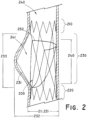
- the frame defines a laterally asymmetric partial sinus portion of the_interior lumen extending around between about 10% and about 90% of the circumference of the frame in the expanded configuration.
- a valve prosthesis radially expandable between a compressed configuration and an expanded configuration.
- the expanded configuration defines an interior lumen adapted to conduct fluid from an annular inlet to an outlet.
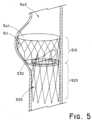
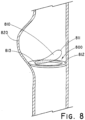
- the valve prosthesis comprises a frame defining a laterally asymmetric partial sinus portion of the interior lumen forming a bulge in the interior lumen extending in a first lateral direction of the frame in the expanded configuration, and a monocuspid valve leaflet having a base attached to the frame and a flexible free edge distal to the base. The free edge is movable between an open configuration permitting fluid flow through the valve orifice and a closed configuration engaging a portion of the frame opposite the partial sinus portion to reduce fluid flow through the valve orifice.
- a method of treating a venous valve-related condition by deploying a valve prosthesis within a body vessel comprises the steps of: 1) inserting the valve prosthesis into a body vessel in a radially compressed configuration; 2) advancing the valve prosthesis within a body vessel; 3) positioning the valve prosthesis at a point of treatment within the body vessel; and 4) expanding the valve prosthesis from the compressed configuration to an expanded configuration to deploy the valve prosthesis within the body vessel, the expanded valve prosthesis laterally distending up to one half of the circumference of the body vessel.
- the valve prosthesis includes a frame moveable from the compressed configuration to the expanded configuration, the frame defining an interior lumen and having a proximal end, a distal end, a lumina1 surface, and an abluminal surface.
- the frame defines a laterally asymmetric partial sinus portion of the interior lumen when the frame is in the expanded configuration.
- the frame further includes a means for regulating fluid flow through the interior lumen positioned within the interior lumen and being attached to the frame.
- the present disclosure relates to an implantable valve prosthesis for regulating fluid flow through a body vessel.
- all technical and scientific terms used herein have the same meaning as commonly understood by one of ordinary skill in the art to which this disclosure pertains. In case of conflict, the present document, including definitions, will control. Preferred methods and materials are described below, although methods and materials similar or equivalent to those described herein can be used in the practice or testing of the present disclosure. All publications, patent applications, patents and other references mentioned herein are incorporated by reference in their entirety. The materials, methods, and examples disclosed herein are illustrative only and not intended to be limiting.
- implantable refers to an ability of a medical device to be positioned at a location within a body, such as within a body lumen.
- frame is used herein to refer to a structure that can be implanted, or adapted for implantation, within the lumen of a body vessel.
- body vessel means any tube-shaped body passage lumen that conducts fluid, including but not limited to blood vessels such as those of the human vasculature system, esophageal, intestinal, billiary, urethral and ureteral passages.
- alloy refers to a substance composed of two or more metals or of a metal and a nonmetal intimately united, for example by chemical or physical interaction. Alloys can be formed by various methods, including being fused together and dissolving in each other when molten, although molten processing is not a requirement for a material to be within the scope of the term "alloy.” As understood in the art, an alloy will typically have physical or chemical properties that are different from its components.
- Proximal means that position or portion of a component which is closest to the patient's heart.
- distal means that position of portion of a component which is furthest from the patient's heart.
- Anategrade fluid flow refers to the flow of fluid in a primary direction of normal movement within a body vessel. For example, in the venous system, antegrade fluid flow proceeds primarily toward the heart.
- Retrograde fluid flow refers to fluid flow in a direction opposite the primary (antegrade) direction of fluid flow. For example, in the venous system, retrograde fluid flow is primarily directed away from the heart.
- biocompatible refers to a material that is substantially nontoxic in the in vivo environment of its intended use, and that is not substantially rejected by the patient's physiological system (i.e., is non-antigenic). This can be gauged by the ability of a material to pass the biocompatibility tests set forth in International Standards Organization ⁇ ISO) Standard No. 10993 and/or the U.S. Pharmacopeia ⁇ USP) 23 and/or the U.S. Food and Drug Administration (FDA) blue book memorandum No.
- ISO International Standards Organization
- U.S. Pharmacopeia ⁇ USP U.S. Pharmacopeia ⁇ USP
- FDA U.S. Food and Drug Administration
- G95-1 entitled "Use of International Standard ISO-10993, Biological Evaluation of Medical Devices Part-1: Evaluation and Testing.” Typically, these tests measure a material's toxicity, infectivity, pyrogenicity, irritation potential, reactivity, hemolytic activity, carcinogenicity and/or immunogenicity.
- a biocompatible structure or material when introduced into a majority of patients, will not cause a significantly adverse, long-lived or escalating biological reaction or response, and is distinguished from a mild, transient inflammation which typically accompanies surgery or implantation of foreign objects into a living organism.
- Valve prostheses may be any medical device that is introduced temporarily or permanently into the body for the prophylaxis or therapy of a medical condition.
- such valve prostheses may include, but are not limited to, heart valve prostheses, venous valve prostheses, artificial organs such as artificial hearts, and ventricular assist devices.
- Typical subjects also referred to herein as "patients" are vertebrate subjects (i.e., members of the subphylum cordata), including, mammals such as cattle, sheep, pigs, goats, horses, dogs, cats and humans.
- Valve prostheses according to the present disclosure preferably comprise a frame having a partial sinus and at least one monocuspid valve member.
- the frame is configured such that when the device is deployed within the body vessel, an artificial partial sinus is formed adjacent the monocuspid valve member such that bodily fluids, for example blood, collecting within the pocket formed around the base of the valve member are more likely to be flushed out on a continual basis due to the advantageous geometry created by the valve member and artificial partial sinus.
- FIG. 1 shows a natural venous valve 10 in which retrograde blood 20 flowing or falling back down and closing the valve is thought to create a series of vortices 21 as it contacts the leaflets. It is believed that the rounded shape of the enlarged natural sinus 30 surrounding the valve 10 facilitates creation of these vortices, thereby preventing blood from pooling or stagnating within the pockets 40 at the base of the valve 10, which may lead to thrombus formation or other problems.
- the frame preferably defines an interior lumen including an artificial partial sinus and include a means for regulating fluid flow through the interior lumen.
- the means for regulating fluid flow is preferably a valve member that beneficially improves the venous valve function served by the natural sinus in the vascular system.
- FIG. 2 depicts a side view of an exemplary prosthesis inwhich the frame 200 defines an interior lumen.
- the frame 200 includes a first or proximal section 210 and a second or distal section 220 that are spaced apart from one another, defining an intermediate section 230 for creating the artificial partial sinus 241 in the body vessel 240.
- the artificial partial sinus 241 is a laterally asymmetric portion of the interior lumen defined by the intermediate section 230 of the frame 200.
- the intermediate section 230 includes an expanded portion 231, having a larger diameter 232 than the diameter 211, 221 of the proximal 210 and distal 220 portions, respectively, of the frame 200, that upon deployment, creates the artificial partial sinus 241 adjacent the valve member 250.
- the distal frame portion 220 and/or proximal frame portion 210 are preferably annular structures (e.g., having circular or elliptical lateral cross-sections).
- the distal frame portion 220 and/or proximal frame portion 210 have a radial force less than the radial force of the intermediate portion 230, thereby allowing the distal and/or proximal frame portions 210, 220 to more compliant to vessel movement than the intermediate portion 230.
- the intermediate portion 230 of the frame 200 defining the partial sinus 241 portion of the interior lumen is preferably characterized by a greater lateral distance between the frame 200 and the longitudinal axis of the proximal 210 or distal 220 portions than the frame 200 in the direction of the partial sinus 241 than in the opposite lateral direction.
- the partial sinus preferably has a longitudinal length 233 that is at least as great as the longitudinal length 240 of the valve member 250.
- the partial sinus 241 is preferably formed by a bulge in the luminal surface of the frame 200 extending away from the interior lumen.
- the partial sinus extends around between about 5% and about 90% the circumference of the interior lumen; between about 10% and about 75% around the circumference of the interior lumen; and between about 25% and about 60% around the circumference of the interior lumen.
- the partial sinus 300 may extend around up to about 75% of the circumference of the frame 301.
- the partial sinus 310 may extend around up to about 50% of the circumference of the frame 311.
- the configuration of the partial sinus may depend on several factors, including body vessel diameter, valve member geometry such as length, slack, and orientation, fluid column pressures at the site of deployment, and other factors.
- the partial sinus may have a longitudinal length at least as great as the longitudinal length of the valve member, permitting the valve member to fully retract within the partial sinus, thereby substantially uninterrupting antegrade flow.
- FIG. 4 depicts another method of creating an artificial partial sinus, whereby the frame 400 includes a first or proximal section 410 and a second or distal section 420 that are spaced apart from one another, defining an intermediate section 430 for creating the artificial partial sinus 441 adjacent the valve member 450 in the body vessel 440.
- the intermediate section 430 comprises a first 431, a second 432, and a third 433 intermediate subsection.
- the third intermediate subsection 433, located between intermediate subsection 431 and 432, extends the length of the artificial partial sinus.
- the illustrative third intermediate subsection 433 has a width 434 and height 435 that can be adjusted to create the desired geometry of the artificial partial sinus 441. Additional subsections may be added as well if desired.
- the expanded frame portion 511 which comprises the proximal section 510 of the frame 500, includes a flared configuration that extends laterally outward in one direction from the distal section 520 (no separately functional intermediate section is present).
- the proximal section 510 includes a portion of the frame 500 defining a laterally asymmetric portion of an interior lumen, extending away from up to half the circumference of the distal section 520.
- a means for regulating fluid flow may be positioned within the interior lumen.
- valve member 530 may be attached about the proximal end 510, while the flared, expanded portion 511 thereabout causes the vessel 540 to bulge outward, thus creating an artificial partial sinus 541about the proximal end of the frame 510.
- the artificial partial sinus 541 comprises a combination of a supported and an unsupported portion in the example of FIG. 5 .
- the frame may have any possible configuration.
- the frame may comprise a mesh or web of interconnecting struts, a wire based frame, and a partially radially compliant frame capable of dynamic adjustability or dynamic movement in response to external forces, such as changes in the dimensions of the lumen of the body vessel.
- the radial compliance of the frame refers to the resistance of the frame to a radial force applied to the abluminal surface of the frame toward the center of the interior lumen.
- FIG. 6 illustrates a frame 600 comprising a tubular mesh 610 of interconnecting struts configured such that a portion 620 of the mesh has a diameter 621 greater than the remaining mesh structure diameter 611.
- This expanded portion 620 defines a bulge in the interior lumen that extends about 50% around the circumference of the frame 600, though in further examples the bulge may extend between about 5% and about 90% around the circumference of the frame; between about 10% and about 75% around the circumference of the frame; and between about 25% and about 60% around the circumference of the frame.
- the expanded portion 620 typically resembles a laterally asymmetric bulge in the frame 600 and may be created, for example, by heat setting the frame 600 on a mandrel having the desired final shape.
- Suitable frames may be made from one or more suitable materials and need only be biocompatible or able to be made biocompatible.
- suitable materials include, without limitation, stainless steel, nitinol, nickel titanium alloy, nonmagnetic nickel-cobalt-chromium-molybdenum alloy, gold, tantalum, platinum or platinum iridium, niobium, tungsten, iconel, ceramic, nickel, titanium, stainless steel/titanium composite, cobalt, chromium, cobalt/chromium alloys, magnesium, aluminum, or other biocompatible metals and/or composites or alloys such as carbon or carbon fiber, cellulose acetate, cellulose nitrate, silicone, cross-linked polyvinyl alcohol (PVA) hydrogel, cross-linked PVA hydrogel foam, polyurethane, polyamide, styrene isobutylene-styrene block copolymer (Kraton), polyethylene teraphthalate, polyurethane, polyamide, polyester, polyortho
- the frame itself, or any portion of the frame may comprise one or more metallic bioabsorbable materials.
- Suitable metallic bioabsorbable materials include magnesium, titanium, zirconium, niobium, tantalum, zinc and silicon and mixtures and alloys.
- a zinc-titanium alloy such as discussed in U.S. Patent 6,287,332 to Bolz et al. , which is incorporated herein by reference in its entirety, can be used.
- the metallic bioabsorbable material can further contain lithium, sodium, potassium, calcium, iron and manganese or mixtures thereof.
- an alloy containing lithium:magnesium or sodium:magnesium can be used.
- the physical properties of the frame can be controlled by the selection of the metallic bioabsorbable material, or by forming alloys of two or more metallic bioabsorbable materials. For example, when 0.1% to 1%, percentage by weight, titanium is added to zinc, the brittle quality of crystalline zinc can be reduced. In another example, when 0.1% to 2%, percentage by weight, gold is added to a zinc-titanium alloy, the grain size of the material is reduced upon cures and further and the tensile strength of the material increases.
- the frame can comprise a bioabsorbable material that can be degraded and absorbed by the body over time to advantageously eliminate a frame or portion thereof from the vessel before, during or after the remodeling process.
- a bioabsorbable material that can be degraded and absorbed by the body over time to advantageously eliminate a frame or portion thereof from the vessel before, during or after the remodeling process.
- a number of bioabsorbable homopolymers, copolymers, or blends of bioabsorbable polymers are known in the medical arts.
- polyesters include, but are not necessarily limited to, polyesters, poly(amino acids), copoly(ether-esters), polyalkylenes oxalates, polyamides, poly(iminocarbonates), polyorthoesters, polyoxaesters, polyamidoesters, polyoxaesters containing amido groups, poly(anhydrides), polyphosphazenes, poly-alpha-hydroxy acids, trimethlyene carbonate, poly-beta-hydroxy acids, polyorganophosphazi nes, polyanhydrides, polyesteramides, polyethylene oxide, polyester-ethers, polyphosphoester, polyphosphoester urethane, cyanoacrylates, poly(trimethylene carbonate), poly(iminocarbonate), polyalkylene oxalates, polyvinylpyrolidone, polyvinyl alcohol, poly-N-(2-hydroxypropyl)-methacrylamide, polyglycols, aliphatic polyesters, poly(orthoesters), poly
- bioabsorbable materials include polymers and co-polymers comprising a polylactic acid, a polyglycolic acid, a polycaprolactone or derivatives thereof.
- Suitable bioabsorbable materials for a frame include: poly(epsilon-caprolactone), poly(dimethyl glycolic acid), poly(hydroxy butyrate), poly(p-dioxanone), polydioxanone, PEO/PLA, PLA, poly(lactide-co-glycolide ), poly(hydroxybutyrate-co-valerate ), poly(glycolic acid-co-trimethylene carbonate), poly(epsilon-caprolactone-co-p-di oxanone), poly-L-glutam ic acid or poly-L-lysine, polylactic acid, polylactide, polyglycolic acid, polyglycolide, poly(D,L-lactic acid), L-polylactic acid, poly(glycolic acid), polyhydroxyval
- the frame can have a compressed and an expanded configuration.
- the expanded configuration can be resiliently further extended in one or more radial directions.
- a frame can expand from a compressed, or unexpanded, delivery configuration to one or more radially expanded deployment configurations, for example through self-expansion or balloon expansion of the frame.
- the expanded configuration can have any suitable cross-sectional configuration, including circular or elliptical.
- the frame can be oriented along the longitudinal axis of a body vessel in the expanded or compressed configurations.
- the frame is self-expanding.
- self-expanding frames can expand toward their pre-compression geometry.
- a self-expandi ng frame can be compressed into a low-profile delivery conformation and then constrained within a delivery system for delivery to a point of treatment in the lumen of a body vessel. At the point of treatment, the self-expanding frame can be released and allowed to subsequently expand to another configuration.
- frames may not be self-expanding.
- frames may be balloon expandable.
- the dimensions of the implantable frame will depend on its intended use. Typically, the collapsed dimension of the frame will usually be in the range from about 1 mm to 10 mm, more usually being in the range from 1.5 mm to 6 mm for vascular applications. The expanded dimension will usually be in the range from about 2 mm to 30 mm, preferably being in the range from about 2.5 mm to 18 mm for vascular applications.
- the frame comprises a means for orienting the frame within a body lumen.
- the frame can comprise a marker, such as a radiopaque portion of the frame that would be seen by remote imaging methods including X-ray, ultrasound, Magnetic Resonance Imaging and the like, or by detecting a signal from or corresponding to the marker.
- the radiopaque indicia may be used to radially or circumferentially orient the valve, such as to orient the partial sinus along the long axis of the vein.
- the delivery device can comprise a frame with indicia relating to the rientation of the frame within the body vessel.
- indicia can be located, for example, on a portion of a delivery catheter that can be correlated to the location of the frame within a body vessel.
- a frame or delivery device may comprise one or more radiopaque materials to facilitate tracking and positioning of the medical device, which may be added in any fabrication method or absorbed into or sprayed onto the surface of part or all of the medical device.
- the degree of radiopacity contrast can be altered by implant content. Radiopacity may be imparted by covalently binding iodine to the polymer monomeric building blocks of the elements of the implant. Common radiopaque materials include barium sulfate, bismuth subcarbonate, and zirconium dioxide. Other radiopaque elements include: cadmium, tungsten, gold, tantalum, bismuth, platinum, iridium, and rhodium. In one preferred example, iodine may be employed for its radiopacity and antimicrobial properties. Radiopacity is typically determined by fluoroscope or x-ray film.
- Prosthetic valves comprise a means for regulating fluid flow through an interior lumen defined by at least a portion of an implantable frame.
- at least one valve member may be attached to the frame to form a prosthetic valve.
- Prosthetic valves comprising at least one valve member can be used to regulate fluid flow in a vein, for example to treat venous valve incompetency.
- One or more prosthetic valves comprising one or more valve members can be implanted in a vein with incompetent native venous valves so as to provide a valve to replace the incompetent native valves therein.
- Monocuspid valve members may allow for a larger artificial partial sinus and increased flushing about the valve member. Further, a monocuspid valve member may be positioned at least partially within the partial sinus such that antegrade fluid flow is substantially unimpeded.
- a monocuspid valve member may comprise a leaflet having a free edge responsive to the flow of fluid through the body vessel.
- a "free edge” refers to a portion of a leaflet that is not attached to the prosthetic valve, but forms a portion of a valve orifice.
- a leaflet free edge is a portion of the edge of the leaflet that is free to move in response to the direction of fluid flow in contact with the leaflet.
- FIGS. 7A and 78 illustrate partial cut-aways (i.e., the frame is not depicted) of a prosthetic valve in a body vessel 700, exposing a valve member comprising a single leaflet 710 with a free edge 711.
- the leaflet 710 is moveable between first 720 and second 725 positions when the prosthesis is placed within a body vessel 700.
- the leaflet 710 permits fluid flow in a first direction, represented by arrow 721, to flow through the vessel 700.
- the pressure created by the flow of fluid exerts a force on one face of the leaflet 710, forcing it toward the vessel wall 703.
- the partial sinus 705 may permit the leaflet 710 to be positioned at least partially within the partial sinus 705 when in the first position 720 such that antegrade fluid 721 flow is substantially unimpeded. Further, the leaflet 710 may have a curvature approximating the curvature of the partial sinus 705 to further enhance the ability of the leaflet 710 to be positioned within the partial sinus 705 when in the first position 720.
- the leaflet 710 substantially prevents fluid flow in a second, opposite direction, represented by arrow 726 from flowing through the prosthesis vessel 700.
- Flow in the second opposite direction 726 is commonly referred to as retrograde flow.
- the leaflet 710 moves to the second position 725 when a pressure change and/or reversal of flow direction exerts a force on an opposite face of the leaflet 710 and forces the leaflet 710 away from the vessel wall 703 and across the lumen 702 of the vessel 700.
- the first position 720 of the leaflet 710 can be considered an open position, and the second position 725 can be considered a closed position.
- the leaflet 710 By moving between these two positions, the leaflet 710 provides a valving function to the vessel 700 allowing it to regulate fluid flow through the vessel 700.
- the degree to which the valve opens to the first position 720 may be varied, for example by adjusting the amount of tension, or slack, built into the leaflet 710.
- a tauter leaflet may only open halfway such that the free edge bisects the vessel opening, particularly if there is less tension across the bottom portion of the leaflet.
- at least the leaflet free edge 711 is permitted to retract within the partial sinus to aid in fluid flow and fluid flushing about the valve member.
- FIG. 8 depicts a cut-away (i.e., the frame is not depicted) of another example of a monocuspid valve prosthesis, wherein the valve prosthesis comprises an interior lumen including a partial sinus region 820 and valve member 800 positioned within the interior lumen.
- the valve member 800 comprises a single leaflet 810 with a free edge 811.
- the leaflet 810 is mounted on a leaflet seat 812 and is operatively connected to the leaflet seat 812 via a hinge 813 allowing the leaflet 810 to move freely in response to flow.
- the valve member 800 sealably engages the leaflet seat 812 to prevent retrograde fluid flow through the interior lumen.
- the partial sinus 820 may permit the valve leaflet 810 to be positioned at least partially within the partial sinus 820 when in an open position such that antegrade fluid flow is substantially unimpeded.
- the leaflet 810 may have a curvature approximating the curvature of the partial sinus 820 to further enhance the ability of the leaflet 810 to be positioned within the partial sinus 820 when in the open position.
- leaflets A wide variety of materials acceptable for use as leaflets are known in the art, and any suitable material can be utilized.
- the material chosen need only be able to perform as described herein, and be biocompatible, or able to be made biocompatible. Examples of suitable materials include natural materials, and synthetic materials.
- ECM extracellular matrix
- the extracellular matrix is typically a collagen-rich substance that is found in between cells in animal tissue and serves as a structural element in tissues. Such an extracellular matrix is preferably a complex mixture of polysaccharides and proteins secreted by cells.
- the extracellular matrix can be isolated and treated in a variety of ways. Following isolation and treatment, it is referred to as an ECM.
- ECM may be isolated from submucosa (including small intestine submucosa), stomach submucosa, urinary bladder submucosa, tissue mucosa, renal capsule, dura mater, liver basement membrane, pericardium or other tissues.
- ECM small intestine submucose ⁇ SIS
- SIS When implanted, SIS can undergo remodeling and can induce the growth of endogenous tissues upon implantation into a host.
- SIS has been used successfully in vascular grafts, urinary bladder and hernia repair, replacement and repair of tendons and ligaments, and dermal grafts.
- SIS is particularly well-suited for use as valve members, such as leaflets.
- autologous tissue can be harvested as well.
- Elastin or Elastin Like Polypetides (ELPs) and the like offer potential as a material to fabricate the flexible covering or discrete shaping members to form a device with exceptional biocompatibility.
- Another alternative is use of allographs such as harvested native valve tissue. Such tissue is commercially available in a cryopreserved state.
- the valve member and preferably a valve leaflet, is formed from explanted biological tissue, such as aortic tissue, that is treated in a manner that improves the biocompatibility of the tissue for an intended use.
- tissue may be treated to improve resistance to post-implantation mineralization.
- the explanted tissue explanted tissue is pre-treated by performing at least one of the following steps: maintaining the explanted tissue at a pH in the range from about 5.0 to about 8.0 and a temperature in the range from about 12 ′′′C to about 30 ′′′C for a sufficient amount of time sufficient to effect the degradation of at least a portion of the cells by autolytic enzymes within the cells; contacting the explanted tissue with a chemical cross-linking agent and then irradiating with X-ray or gamma radiation; contacting the explanted tissue with a tanning fluid including formaldehyde or glutaraldehyde; or placing tissue explanted tissue within an atmosphere of substantially unpressurized vapor of containing glutaraldehyde, and maintaining the tissue within the atmosphere of substantially unpressurized vapor in a manner sufficient to provide substantially uniform application of the fixative solution for a period of time to cause the desired fixation of said tissue.
- polyesters such as poly(ethylene terephthalate), polylactide, polyglycolide and copolymers thereof; fluorinated polymers, such as polytetrafluoroethylene (PTFE), expanded PTFE and poly(vinylidene fluoride ⁇ ; polysiloxanes, including polydimethyl siloxane; and polyurethanes, including polyetherurethanes, polyurethane ureas, polyetherurethane ureas, polyurethanes containing carbonate linkages and polyurethanes containing siloxane segments.
- PTFE polytetrafluoroethylene
- poly(vinylidene fluoride ⁇ such as polytetrafluoroethylene (PTFE), expanded PTFE and poly(vinylidene fluoride ⁇
- polysiloxanes including polydimethyl siloxane
- polyurethanes including polyetherurethanes, polyurethane ureas, polyetherurethane ureas, polyurethan
- the valve member may also be made of one or more polymers that do not require treatment or modification to be biocompatible.
- the valve member may include a biocompatible polyurethane.
- THO RALON THORALON
- THORALON THORALON
- methods of manufacturing this material are disclosed in U.S. Pat. Application Publication No. 2002/0065552 A1 and U.S. Pat. Nos. 4,861,830 and 4,675,361 , each of which is incorporated herein by reference in their entirety.
- THORALON is a polyurethane based polymer (referred to as BPS-215) blended with a siloxane containing surface modifying additive (referred to as SMA-300).
- BPS-215 polyurethane based polymer
- SMA-300 siloxane containing surface modifying additive
- Base polymers containing urea linkages can also be used.
- concentration of the surface modifying additive may be in the range of 0.5% to 5% by weight of the base polymer.
- THORALON can be manipulated to provide either a porous or nonporous material. Formation of porous THORALON is described, for example, in U.S. Pat. No 6,752,826 and U.S. Pat Application Publication No. 2003/0149471 A1 , both of which are incorporated herein by reference in their entirety.
- the pores in the polymer may have an average pore diameter from about 1 micron to about 400 microns. Preferably the average pore diameter is from about 1 micron to about 100 microns, and more preferably is from about 1 micron to about 10 microns.
- biocompatible polyurethanes/ polycarbamates and urea linkages may also be employed.
- Biocompatible CON type polymers modified with cationic, anionic and aliphatic side chains may also be used. See, for example, U.S. Pat. No. 5,017,664 , which is incorporated herein by reference in its entirety.
- biocompatible CON type polymers include: segmented polyurethanes, such as BIOSPAN; polycarbonate urethanes, such as BIONATE; polyetherurethanes, such as ELASTHANE; (all available from POLYMER TECHNOLOGY GROUP, Berkeley, CA); siloxane-polyurethanes, such as ELAST-EON 2 and ELAST-EON 3 (AORTECH BIOMATERIALS, Victoria, Australia); polytetramethyleneoxide (PTMO) and polydimethylsiloxane (PDMS ⁇ polyether-based aromatic siloxane-polyurethanes, such as PURSIL-10, -20, and -40 TSPU; PTMO and PDMS polyether-based aliphatic siloxane-polyurethanes, such as PURSIL AL-5 and AL-10 TSPU; aliphatic, hydroxy-terminated polycarbonate and PDMS polycarbonate-based siloxane-polyurethanes, such as C
- any of these biocompatible CON type polymers may be endcapped with surface active end groups, such as, for example, polydimethylsiloxane, fluoropolymers, polyolefin, polyethylene oxide, or other suitable groups. See, for example the surface active end groups disclosed in U.S. Pat. No. 5,589,563 , which is incorporated herein by reference in its entirety.
- THORALON leaflets may be reinforced with fibers.
- the fibers may include any suitable material, but preferably include nanofibers from electrospinning. An electrospun layer of THORALON may be applied to the prosthesis, and further processing may be applied to bring the leaflet construct up to desired specifications.
- a valve member may be applied to the prosthetic valve with any suitable attachment mechanism, such as sutures, dipping, adhesives, bonding, tissue welding, barbs or other integral engaging structures along the frame or struts, self-adhesion between regions of the material, chemical adhesion between the valve member and frame, spraying, cross-linking, and the like.
- the attachment mechanism chosen will depend on the nature of the frame and valve members.
- the biocompatible polyurethane may be applied as a solution. If necessary, gentle heating and/or agitation, such as stirring, may be employed to cause substantial dissolution.
- the valve member may be sewn to struts of the frame.
- the prosthetic valve further comprises a graft material operatively attached to the frame.
- a graft material operatively attached to the frame.
- the graft material is preferably a remodelable material and is biocompatible, or able to be made biocompatible.
- graft material may include a film, a coating, a sheet of biocompatible fabrics, non-woven materials or porous materials.
- biocompatible polymers from which porous sheets can be formed include polyesters, such as poly(ethylene terephthalate), polylactide, polyglycolide and copolymers thereof; fluorinated polymers, such as polytetrafluoroethylene (PTFE), expanded PTFE and poly(vinylidene fluoride); polysiloxanes, including polydimethyl siloxane; and polyurethanes, including polyetherurethanes, polyurethane ureas, polyetherurethane ureas, polyurethanes containing carbonate linkages and polyurethanes containing siloxane segments.
- polyesters such as poly(ethylene terephthalate), polylactide, polyglycolide and copolymers thereof
- fluorinated polymers such as polytetrafluoroethylene (PTFE), expanded PTFE and poly(vinyliden
- materials that are not inherently biocompatible may be subjected to surface modifications in order to render the materials biocompatible.
- surface modifications include polymerization of biocompatible polymers from the material surface, coating of the surface with a crosslinked biocompatible polymer, and chemical modification with biocompatible functional groups.
- any polymer that may be formed into a porous sheet can be used to make a flexible covering, provided the final porous material is biocompatible.
- Polymers that can be formed into a porous sheet include polyolefins, polyacrylonitrile, nylons, polyaramids and polysulfones, in addition to polyesters, fluorinated polymers, polysiloxanes and polyurethanes as listed above.
- Suitable natural graft materials include collagen and extracellular matrix (ECM) material, such as submucosa.
- ECM extracellular matrix
- SIS small intestine submucose
- Elastin or Elastin Like Polypetides (ELPs) and the like offer potential as a material to fabricate the flexible covering or discrete shaping members to form a device with exceptional biocompatibility.
- allographs such as harvested native valve tissue. Such tissue is commercially available in a cryopreserved state.
- a prosthetic valve may optionally include a means for anchoring the valve within a body vessel.
- suitable anchoring means include anchoring elements (e.g., barbs, hooks), suturing, stapling, searing, bonding, adhesives, gluing, or otherwise adhering the medical device to the vessel wall or combinations thereof.
- the prosthetic valve may be secured in place with one or more anchoring elements.
- a wide variety of structural features are acceptable for use in medical devices as anchoring elements, and any suitable structural feature can be used.
- individual barbs may be used to implant the prosthetic valve into the vessel.
- the barbs may be secured to the prosthetic valve by any means known to one skilled in the art, including but not limited to welding, stitching, bonding, and adhesives. Desirably, barbs may be attached to the prosthesis frame.
- the number, arrangement, and configuration of barbs can vary according to design preference and the clinical use of the device.
- the barbs can have any suitable shape, including points or "fish hook”-like configurations.
- the barbs may or may not penetrate the vein wall, depending on their design and other factors, including the thickness and type of covering used.
- bioadhesives may be used for attachment.
- the bioadhesive can be included in any suitable part of the prosthetic valve.
- the bioadhesive is attached to the abluminal surface of the prosthetic valve.
- Selection of the type of bioadhesive, the portions of the prosthetic valve comprising the bioadhesive, and the manner of attaching the bioadhesive to the prosthetic valve can be chosen to perform a desired function upon implantation.
- the bioadhesive can be selected to promote increased affinity of the desired portion of prosthetic valve to the section of the body vessel against which it is urged.
- Suitable bioadhesives include, but are not limited to, the following:
- bioadhesives that may be used include, but are not limited to: FOCALSEAL ® (biodegradable eosin-PEG-lactide hydrogel requiring photopolymerization with Xenon light wand) produced by Focal; BERIPLAST ® produced by Adventis-Bering; VIVOSTAT ® produced by ConvaTec (Bristol-Meyers-Squibb); SEALAGENTM produced by Baxter; FIBRX ® (containing virally inactivated human fibrinogen and inhibited-human thrombin) produced by CryoLife; TISSEEL ® (fibrin glue composed of plasma derivatives from the last stages in the natural coagulation pathway where soluble fibrinogen is converted into a solid fibrin) and TISSUCOL ® produced by Baxter; QLIIXJL ® (Biological Active Component and Thrombin) produced by Omrix Biopharm; a PEG-collagen conjugate produced by Cohesion (
- the prosthetic valve can include one or more bioactive agents.
- the bioactive agent can be included in any suitable part of the prosthetic valve. Selection of the type of bioactive, the portions of the prosthetic valve comprising the bioactive agent, and the manner of attaching the bioactive agent to the prosthetic valve can be chosen to perform a desired function upon implantation.
- the bioactive material can be selected to treat indications such as vascular graft stenosis.
- the bioactive materials can be attached to the prosthetic valve in any suitable manner.
- a bioactive agent can be combined with a biocomplatible polyurethane, impregnated in the valve members, positioned within or on a graft material, or attached to the surface of the prosthetic valve.
- the bioactive agent can be selected to perform one or more desired biological functions.
- the abluminal surface of the prosthetic valve can comprise a bioactive selected to promote the ingrowth of tissue from the interior wall of a body vessel, such as a growth factor.
- An anti-angiogenic or antneoplaslic bioactive such as paclitaxel, sirolimus, or a rapamycin analog, or a metalloproteinase inhibitor such as batimastaat can be incorporated in or coated on the frame or graft material to mitigate or prevent undesired conditions in the vessel wall, such as restenosis.
- Many other types of bioactive agents can be incorporated in the prosthetic valve.
- Bioactive materials for use in biocompatible coatings include those suitable for coating an implantable medical device.
- the bioactive agent can include, for example, one or more of the following: antiproliferative agents (sirolimus, paclitaxel, actinomycin D, cyclosporine), immunomodulating drugs (tacrolimus, dexamethasone), metalloproteinase inhibitors (such as batimastat), antisclerosing agents (such as collagenases, halofuginone), prohealing drugs (nitric oxide donors, estradiols), mast cell inhibitors and molecular interventional bioactive agents such as c-myc antisense compounds, thromboresistant agents, thrombolytic agents, antibiotic agents, anti-tumor agents, antiviral agents, anti- angiogenic agents, angiogenic agents, anti-mitotic agents, anti-inflammatory agents, angiostatin agents, endostatin agents, cell cycle regulating agents, genetic agents, including hormones such as estrogen, their homologs,
- Prosthetic valves comprising an antithrombogenic bioactive agent are particularly preferred for implantation in areas of the body that contact blood.
- an antithrombogenic bioactive agent can be coated on the valve member surface.
- An antithrombogenic bioactive agent is any bioactive agent that inhibits or prevents thrombus formation within a body vessel.
- the prosthetic valve can comprise any suitable antithrombogenic bioactive agent.
- Types of antithrombotic bioactive agents include anticoagulants, antiplatelets, and fibrinolytics.
- Anticoagulants are bioactive materials which act on any of the factors, cofactors, activated factors, or activated cofactors in the biochemical cascade and inhibit the synthesis of fibrin.
- Antiplatelet bioactive agents inhibit the adhesion, activation, and aggregation of platelets, which are key components of thrombi and play an important role in thrombosis.
- Fibrinolytic bioactive agents enhance the fibrinolytic cascade or otherwise aid in dissolution of a thrombus.
- antithrombotics include but are not limited to anticoagulants such as thrombin, Factor Xa, Factor VIia and tissue factor inhibitors; antiplatelets such as glycoprotein IIb/IIIa, thromboxane A2, ADP-induced glycoprotein IIb/IIIa, and phosphodiesterase inhibitors; and fibrinolytics such as plasminogen activators, thrombin activatable fibrinolysis inhibitor (TAFI) inhibitors, and other enzymes which cleave fibrin.
- anticoagulants such as thrombin, Factor Xa, Factor VIia and tissue factor inhibitors
- antiplatelets such as glycoprotein IIb/IIIa, thromboxane A2, ADP-induced glycoprotein IIb/IIIa, and phosphodiesterase inhibitors
- fibrinolytics such as plasminogen activators, thrombin activatable fibrinolysis inhibitor (TAFI) inhibitors, and other enzymes which cleave fibrin.
- TAFI thrombin activa
- antithrombotic bioactive agents include anticoagulants such as heparin, low molecular weight heparin, covalent heparin, synthetic heparin salts, coumadin, bivalirudin (hirulog), hirudin, argatroban, ximelagatran, dabigatran, dabigatran etexilate, D-phenalanyl-L-poly-L-argi nyl, chloromethy ketone, dalteparin, enoxaparin, nadroparin, danaparoid, vapiprost, dextran, dipyridamole, omega-3 fatty acids, vitronectin receptor antagonists, DX- 9065a, CI-1083, JTV-803, razaxaban, BAY 59-7939, and LY-51,7717; antiplatelets such as eftibatide, tirofiban, orbofiban, lotrafiban, abcixima
- prosthetic valves comprising a thrombolytic bioactive agent.
- the thrombolytic bioactive agent is positioned on the luminal surface of the prosthetic valve or within the valve members.
- Thrombolytic agents are used to dissolve blood clots that may adversely affect blood flow in body vessels.
- a thrombolytic agent is any therapeutic agent that either digests fibrin fibres directly or activates the natural mechanisms for doing so.
- the prosthetic valve can comprise any suitable thrombolytic agent.
- Examples of commercial thrombolytics include, but are not limited to, Abbokinase (urokinase), Abbokinase Open-Cath (urokinase), Activase (alteplase, recombinant), Eminase (anitstreplase), Retavase (reteplase, recombinant), and Streptase ⁇ streptokinase).
- Other commonly used names are anisoylated plasminogen-streptoki nase activator complex; APSAC; tissue-type plasminogen activator (recombinant); t-PA; rt-PA.
- a bioactive agent can be incorporated in or applied to portions of the prosthetic valve by any suitable method that permits adequate retention of the bioactive agent material and the effectiveness thereof for an intended purpose upon implantation in the body vessel.
- the configuration of the bioactive agent on or in the prosthetic valve will depend in part on the desired rate of elution for the bioactive agent.
- Bioactive agents can be coated directly on the prosthetic valve surface or can be adhered to a prosthetic valve surface by means of a coating.
- an antithrombotic bfoactive agent can be blended with a polymer and spray or dip coated on the device surface.
- a bioactive agent material can be posited on the surface of the prosthetic valve and a porous coating layer can be posited over the bioactive agent material.
- the bioactive agent material can diffuse through the porous coating layer.
- the coating layer can also be nonporous wherein the rate of diffusion of the bioactive agent material through the coating layer is controlled by the rate of dissolution of the bioactive agent material in the coating layer.
- Prosthetic valves may be configured for intraluminal delivery to a body vessel.
- a prosthetic valve may preferably be compressed to a delivery configuration within a retaining sheath that is part of a delivery system, such as a catheter-based system.
- the prosthetic valve can be expanded, for example, by inflating a balloon from inside the prosthetic valve.
- the delivery configuration can be maintained prior to deployment of the prosthetic valve by any suitable means, including a sheath, a suture, a tube or other restraining material around all or part of the compressed prosthetic valve, or other methods.
- Prosthetic valves can be deployed in a body lumen by any means appropriate to their design.
- the prosthetic valves can be adapted for deployment using conventional methods and employing percutaneous transluminal catheter devices.
- the prosthetic valves are designed for deployment by any of a variety of in situ expansion means.
- the prosthetic valve may be mounted onto a catheter that holds the prosthesis as it is delivered through the body lumen and then releases the prosthetic valve and allows it to self-expand into contact with the body lumen. This deployment is effected after the prosthetic valve has been introduced percutaneously, transported transluminally and positioned at a desired location by means of the catheter.
- the self-expanding prosthetic valve may be deployed according to well-known deployment techniques for self-expanding medical devices.
- the prosthesis may be positioned at the distal end of a catheter with a removable sheath or sleeve placed over the prosthetic valve to hold the prosthetic valve in a contracted state with a relatively small diameter.
- the prosthetic valve may then be implanted at the point of treatment by advancing the catheter over a guidewire to the location of the lesion and then withdrawing the sleeve from over the prosthesis.
- the prosthetic valve will automatically expand and exert pressure on the wall of the blood vessel at the site of the lesion.
- the catheter, sleeve, and guidewire may then be removed from the patient.
- a bioabsorbable suture or sheath can be used to maintain a self-expanding prosthetic valve f n a compressed configuration both prior to and after deployment.
- the prosthetic valve can expand within the body vessel.
- a portion of the prosthesis can be restrained with a bioabsorbable material and another portion allowed to expand immediately upon implantation.
- a self-expanding frame can be partially restrained by a bioabsorbable material upon deployment and later expand as the bioabsorbable material is absorbed.
- the prosthetic valve is first positioned to surround a portion of an inflatable balloon catheter.
- the prosthetic valve, with the balloon catheter inside is configured at a first, collapsed diameter.
- the prosthesis and the inflatable balloon are percutaneously introduced into a body lumen, following a previously positioned guidewire.
- a rapid exchange prosthesis delivery balloon catheter allows exchange from a balloon angioplasty catheter to a prosthesis delivery catheter without the need to replace the angioplasty catheter guide wire with an exchange-length wire guide before exchanging the catheters.
- the prosthesis may be tracked by a fluoroscope, until the balloon portion and associated prosthetic valve are positioned within the body passageway at the point where the prosthesis is to be placed.
- the balloon is inflated and the prosthesis is expanded by the balloon portion from the collapsed diameter to a second expanded diameter.
- the balloon is deflated and the catheter is withdrawn, leaving the prosthetic valve in place.
- the prosthetic valve may be covered by a removable sheath during delivery to protect both the prosthesis and the vessels.
- Methods for delivering a prosthetic valve as described herein to any suitable body vessel are also provided, such as a vein, artery, biliary duct, ureteral vessel, body passage or portion of the alimentary canal.
- Still other aspects provide methods of treating a subject, which can be animal or human, comprising the step of providing one or more prostheses attached to one or more valve members, as described herein.
- methods of treatment may also provide the step of delivering a prosthetic valve to a point of treatment in a body vessel, or deploying a prosthetic valve at the point of treatment, wherein the prosthetic valves are as described herein.
- the method comprises a step of delivering a prosthetic valve as described herein to a point of treatment in a body vessel, and deploying the prosthesis at the point of treatment.
- the delivering step can comprise delivery by surgical or by percutaneous delivery techniques known to those skilled in the art.
- venous valve insufficiency a condition presenting symptoms that can be diagnostically associated with improper function of one or more venous valves.
- venous valve related condition refers to any condition presenting symptoms that can be diagnostically associated with improper function of one or more venous valves.
- natural valves are positioned along the length of the vessel in the form of leaflets disposed annularly along the inside wall of the vein which open to permit blood flow toward the heart and close to prevent back flow.
- venous valves act as open to permit the flaw of fluid in the desired direction, and close upon a change in pressure, such as a transition from systole to diastole.
- pressure forces the valve leaflets apart as they flex in the direction of blood flow and move towards the inside wall of the vessel, creating an opening therebetween for blood flow.
- Functioning leaflets return to a closed position to restrict or prevent blood flow in the opposite, i.e. retrograde, direction after the pressure is relieved.
- the leaflets when functioning properly, extend radially inwardly toward one another such that the tips contact each other to block backflow of blood.
- Two examples of venous valve related conditions are chronic venous insufficiency and varicose veins.
- valves in a vein will allow deleterious retrograde flow to occur.
- blood may collect, or pool, in vessels beneath the valve. This pooling of blood can cause an increase in the venous pressure below the valve.
- Venous valves that allow such deleterious retrograde flow are known as incompetent or inadequate venous valves.
- the condition resulting from such incompetent venous valves is known as venous valve insufficiency. In the condition of venous valve insufficiency, the venous valve leaflets do not function properly.
- Incompetent venous valves can cause the veins to bulge, can cause swelling in the patient's lower extremities, and can result in varicose veins and/or chronic venous insufficiency. If left untreated, venous valve insufficiency can cause venous stasis ulcers of the skin and subcutaneous tissue.
- methods of treating a venous valve related condition may comprise the step of providing one or more medical devices comprising implantable frames and/or valve prostheses as described herein.
- Methods of treatment may comprise the step of providing one or more frames attached to one or more valve leaflets.
- methods of treatment may also include the steps of delivering a medical device to a point of treatment in a body vessel, and deploying a medical device at the point of treatment, wherein the medical devices are as described herein.
- Such medical devices can be inserted intravascularly, for example from an implantation catheter.
- the medical devices can function as a replacement venous valve, or enhance venous valve function by bringing incompetent valve leaflets into closer proximity.
- venous valve function can be provided by an implanted medical device.
- a medical device comprising an implantable frame may be placed in a human leg having greater saphenous vein (GSV ⁇ and femoral vein which adjoin at the sapheno-femoral junction.
- the medical device is implanted within the GSV near the medial side of the knee and a point prior to the sapheno-femoral junction.
- the medical device functions as a valve to prevent or reduce reflux of venous blood from the sapheno-femoral junction in a direction down toward the medial side of the knee.
- Such occlusion may be effective to treat varicosities that commonly occur in lower portions of the leg, e.g. portions occurring below the knee.
- the medical device is preferably implanted from a delivery catheter via percutaneous access to the GSV, for example by the Seldinger technique or any other suitable technique.
- an access needle can be passed through the skin to access the GSV, and a wire guide can be passed through the access needle and into the vein.
- wire guide Prior to deployment of an inverted occlusion device, wire guide can be used for any number of conventional procedures including catheterization and imaging procedures in order to locate the sapheno-femoral junction. After any such preliminary procedures that are performed, the wire guide can be used in a deployment procedure for an inflatable occlusion device.
- Tne preferred method of treating a venous valve-related condition by deploying a valve prosthesis within a body vessel comprising the steps of: inserting valve prosthesis into a body vessel in a radially compressed configuration, advancing the valve prosthesis within a body vessel; positioning the valve prosthesis at a point of treatment within the body vessel; and expanding the valve prosthesis from the compressed configuration to the expanded configuration to deploy the valve prosthesis within the body vessel, the expanded valve prosthesis laterally distending up to one half of the circumference of the body vessel.
- the valve prosthesis may include: a frame moveable from the compressed configuration to an expanded configuration, the frame defining an interior lumen and having a proximal end, a distal end, a luminal surface, and an abluminal surface; the frame defining a laterally asymmetric partial sinus portion of the interior lumen when the frame is in the expanded configuration; and a means for regulating fluid flow through the interior lumen positioned within the interior lumen and being attached to the frame.
- the means for regulating fluid flow through the interior lumen may be a monocuspid valve leaflet having a base attached to the frame and a flexible free edge distal to the base, the free edge adapted to form a valve orifice moveable within the interior lumen to modify fluid flow therethrough by moving between an open configuration permitting fluid flow through the valve orifice and a closed configuration engaging a portion of the frame opposite the partial sinus portion to reduce fluid flow through the lumen.
- the disclosure relates to an expandable valve prosthesis for regulating flow through a body vessel.
- the prosthesis comprises a frame (200) configured to form a laterally asymmetric partial sinus and a valve member (250).
- the disclosure also provides a valve prosthesis in accordance with the following clauses.
Applications Claiming Priority (4)
| Application Number | Priority Date | Filing Date | Title |
|---|---|---|---|
| US93089007P | 2007-05-17 | 2007-05-17 | |
| PCT/US2008/063838 WO2008144476A1 (fr) | 2007-05-17 | 2008-05-16 | Valve prosthétique unicuspide présentant un sinus partiel |
| EP18203549.3A EP3473213A1 (fr) | 2007-05-17 | 2008-05-16 | Valve prosthétique unicuspide présentant un sinus partiel |
| EP08755648.6A EP2150208B2 (fr) | 2007-05-17 | 2008-05-16 | Valve prosthétique unicuspide présentant un sinus partiel |
Related Parent Applications (2)
| Application Number | Title | Priority Date | Filing Date |
|---|---|---|---|
| EP18203549.3A Division EP3473213A1 (fr) | 2007-05-17 | 2008-05-16 | Valve prosthétique unicuspide présentant un sinus partiel |
| EP08755648.6A Division EP2150208B2 (fr) | 2007-05-17 | 2008-05-16 | Valve prosthétique unicuspide présentant un sinus partiel |
Publications (2)
| Publication Number | Publication Date |
|---|---|
| EP4233796A2 true EP4233796A2 (fr) | 2023-08-30 |
| EP4233796A3 EP4233796A3 (fr) | 2023-10-18 |
Family
ID=39667219
Family Applications (3)
| Application Number | Title | Priority Date | Filing Date |
|---|---|---|---|
| EP18203549.3A Pending EP3473213A1 (fr) | 2007-05-17 | 2008-05-16 | Valve prosthétique unicuspide présentant un sinus partiel |
| EP23176215.4A Pending EP4233796A3 (fr) | 2007-05-17 | 2008-05-16 | Valve prosthétique unicuspide présentant un sinus partiel |
| EP08755648.6A Active EP2150208B2 (fr) | 2007-05-17 | 2008-05-16 | Valve prosthétique unicuspide présentant un sinus partiel |
Family Applications Before (1)
| Application Number | Title | Priority Date | Filing Date |
|---|---|---|---|
| EP18203549.3A Pending EP3473213A1 (fr) | 2007-05-17 | 2008-05-16 | Valve prosthétique unicuspide présentant un sinus partiel |
Family Applications After (1)
| Application Number | Title | Priority Date | Filing Date |
|---|---|---|---|
| EP08755648.6A Active EP2150208B2 (fr) | 2007-05-17 | 2008-05-16 | Valve prosthétique unicuspide présentant un sinus partiel |
Country Status (4)
| Country | Link |
|---|---|
| US (1) | US8403979B2 (fr) |
| EP (3) | EP3473213A1 (fr) |
| CA (1) | CA2686665A1 (fr) |
| WO (1) | WO2008144476A1 (fr) |
Families Citing this family (50)
| Publication number | Priority date | Publication date | Assignee | Title |
|---|---|---|---|---|
| WO2004030568A2 (fr) * | 2002-10-01 | 2004-04-15 | Ample Medical, Inc. | Dispositifs, systemes et procedes pour ajouter, reparer ou remplacer un feuillet de valvule cardiaque natif |
| US7766973B2 (en) * | 2005-01-19 | 2010-08-03 | Gi Dynamics, Inc. | Eversion resistant sleeves |
| WO2008113193A1 (fr) * | 2007-03-22 | 2008-09-25 | Carag Ag | Endoprothèse vasculaire à valvule |
| US8403979B2 (en) | 2007-05-17 | 2013-03-26 | Cook Medical Technologies Llc | Monocuspid prosthetic valve having a partial sinus |
| WO2009052207A2 (fr) | 2007-10-17 | 2009-04-23 | Hancock Jaffe Laboratories | Valvule biologique pour insuffisance valvulaire veineuse |
| US8679176B2 (en) | 2007-12-18 | 2014-03-25 | Cormatrix Cardiovascular, Inc | Prosthetic tissue valve |
| US8257434B2 (en) | 2007-12-18 | 2012-09-04 | Cormatrix Cardiovascular, Inc. | Prosthetic tissue valve |
| MX2011008735A (es) | 2009-02-18 | 2012-01-12 | Cormatrix Cardiovascular Inc | Composiciones y metodos para prevenir la arritmia cardiaca. |
| US8579964B2 (en) | 2010-05-05 | 2013-11-12 | Neovasc Inc. | Transcatheter mitral valve prosthesis |
| US20120130468A1 (en) * | 2010-07-27 | 2012-05-24 | Fred Khosravi | Methods and apparatus for treating neurovascular venous outflow obstruction |
| DE102011009555A1 (de) * | 2011-01-21 | 2012-07-26 | Aesculap Ag | Gefäßprothese mit integrierter Aortenklappe |
| DE102011000400A1 (de) * | 2011-01-28 | 2012-08-02 | Aesculap Ag | Conduit-Klappenprothese und Verfahren zu ihrer Herstellung |
| US9308087B2 (en) | 2011-04-28 | 2016-04-12 | Neovasc Tiara Inc. | Sequentially deployed transcatheter mitral valve prosthesis |
| US9554897B2 (en) | 2011-04-28 | 2017-01-31 | Neovasc Tiara Inc. | Methods and apparatus for engaging a valve prosthesis with tissue |
| JP2014519906A (ja) | 2011-05-27 | 2014-08-21 | コーマトリックス カーディオバスキュラー, インコーポレイテッド | 滅菌された無細胞の細胞外マトリックス組成物及びその作製方法 |
| US10940167B2 (en) | 2012-02-10 | 2021-03-09 | Cvdevices, Llc | Methods and uses of biological tissues for various stent and other medical applications |
| ITTO20120372A1 (it) * | 2012-04-27 | 2013-10-28 | Marcio Scorsin | Protesi valvolare cardiaca monocuspide |
| US9345573B2 (en) | 2012-05-30 | 2016-05-24 | Neovasc Tiara Inc. | Methods and apparatus for loading a prosthesis onto a delivery system |
| AU2014214700B2 (en) | 2013-02-11 | 2018-01-18 | Cook Medical Technologies Llc | Expandable support frame and medical device |
| US9572665B2 (en) | 2013-04-04 | 2017-02-21 | Neovasc Tiara Inc. | Methods and apparatus for delivering a prosthetic valve to a beating heart |
| EP2918248A1 (fr) | 2014-03-11 | 2015-09-16 | Epygon Sasu | Valvule/endoprothèse expansible et dispositif de mise en place |
| CN106456330B (zh) * | 2014-05-21 | 2021-05-25 | 奥斯卡·马莱蒂 | 用于治疗导致影响下肢的逆流的疾病的人工瓣膜 |
| EP3928743A1 (fr) | 2014-06-26 | 2021-12-29 | Boston Scientific Scimed Inc. | Dispositifs médicaux et procédés pour prévenir le reflux biliaire après une chirurgie bariatrique |
| US9238090B1 (en) | 2014-12-24 | 2016-01-19 | Fettech, Llc | Tissue-based compositions |
| US10463470B2 (en) | 2015-07-31 | 2019-11-05 | Cook Medical Technologies Llc | Methods of making a prosthesis with a smooth covering |
| CA2998576A1 (fr) * | 2015-10-13 | 2017-04-20 | Venarum Medical, Llc | Valvule implantable, et procede |
| US10433952B2 (en) | 2016-01-29 | 2019-10-08 | Neovasc Tiara Inc. | Prosthetic valve for avoiding obstruction of outflow |
| US11241307B2 (en) * | 2016-10-13 | 2022-02-08 | Boston Scientific Scimed, Inc. | Replacement heart valve with diaphragm |
| WO2018081490A1 (fr) * | 2016-10-28 | 2018-05-03 | St. Jude Medical, Cardiology Division, Inc. | Valvule mitrale prothétique |
| US10959841B2 (en) * | 2016-11-15 | 2021-03-30 | Hancock Jaffe Laboratories, Inc. | Implantable vein frame |
| CA3042588A1 (fr) | 2016-11-21 | 2018-05-24 | Neovasc Tiara Inc. | Procedes et systemes de retraction rapide d'un systeme de pose de valvule cardiaque transcatheter |
| US10653523B2 (en) | 2017-01-19 | 2020-05-19 | 4C Medical Technologies, Inc. | Systems, methods and devices for delivery systems, methods and devices for implanting prosthetic heart valves |
| US10561495B2 (en) | 2017-01-24 | 2020-02-18 | 4C Medical Technologies, Inc. | Systems, methods and devices for two-step delivery and implantation of prosthetic heart valve |
| US20180256329A1 (en) * | 2017-03-07 | 2018-09-13 | 4C Medical Technologies, Inc. | Systems, methods and devices for prosthetic heart valve with single valve leaflet |
| CA3073834A1 (fr) | 2017-08-25 | 2019-02-28 | Neovasc Tiara Inc. | Prothese de valvule mitrale transcatheter a deploiement sequentiel |
| EP4233793A1 (fr) | 2017-10-19 | 2023-08-30 | Anteris Technologies Corporation | Valvule cardiaque de remplacement |
| CN109745144B (zh) * | 2017-11-06 | 2020-06-12 | 先健科技(深圳)有限公司 | 覆膜支架 |
| BR112020021304A2 (pt) | 2018-05-18 | 2021-01-26 | Admedus Corporation | válvula cardíaca invertida para substituição de válvula transcateter |
| EP3793482A4 (fr) | 2018-05-18 | 2022-03-16 | Anteris Technologies Corporation | Ensemble valve cardiaque de remplacement avec une valve chargée de manière distale à partir d'un stent |
| AU2019269738A1 (en) | 2018-05-18 | 2020-11-19 | Anteris Technologies Corporation | Heart valve with gathered sealing region |
| US11857441B2 (en) | 2018-09-04 | 2024-01-02 | 4C Medical Technologies, Inc. | Stent loading device |
| CA3118599A1 (fr) | 2018-11-08 | 2020-05-14 | Neovasc Tiara Inc. | Deploiement ventriculaire d'une prothese de valvule mitrale transcatheter |
| JP7438236B2 (ja) | 2019-04-01 | 2024-02-26 | ニオバスク ティアラ インコーポレイテッド | 制御可能に展開可能な補綴弁 |
| EP3952792A4 (fr) | 2019-04-10 | 2023-01-04 | Neovasc Tiara Inc. | Valvule prothétique à circulation sanguine naturelle |
| CA3140925A1 (fr) | 2019-05-20 | 2020-11-26 | Neovasc Tiara Inc. | Dispositif d'introduction avec mecanisme d'hemostase |
| CN114144144A (zh) | 2019-06-20 | 2022-03-04 | 内奥瓦斯克迪亚拉公司 | 低轮廓假体二尖瓣 |
| US11931253B2 (en) | 2020-01-31 | 2024-03-19 | 4C Medical Technologies, Inc. | Prosthetic heart valve delivery system: ball-slide attachment |
| US20230248513A1 (en) | 2020-07-07 | 2023-08-10 | Anteris Technologies Corporation | Expandable frame for improved hemodynamic performance of transcatheter replacement heart valve |
| WO2022048585A1 (fr) * | 2020-09-04 | 2022-03-10 | 杭州诺谊医疗科技有限公司 | Endoprothèse de valvule veineuse d'intervention et prothèse de valvule veineuse |
| US11622853B1 (en) | 2022-09-30 | 2023-04-11 | Anteris Technologies Corporation | Prosthetic heart valves |
Citations (15)
| Publication number | Priority date | Publication date | Assignee | Title |
|---|---|---|---|---|
| US3966401A (en) | 1974-07-01 | 1976-06-29 | Hancock Laboratories Incorporated | Preparing natural tissue for implantation so as to provide improved flexibility |
| US4675361A (en) | 1980-02-29 | 1987-06-23 | Thoratec Laboratories Corp. | Polymer systems suitable for blood-contacting surfaces of a biomedical device, and methods for forming |
| US4798611A (en) | 1986-10-14 | 1989-01-17 | Hancock Jaffe Laboratories | Enhancement of xenogeneic tissue |
| US4800603A (en) | 1987-01-30 | 1989-01-31 | Jaffe Norman R | Tissue fixation with vapor |
| US4813958A (en) | 1986-10-14 | 1989-03-21 | Hancock Jaffe Laboratories | Crosslinked anisotropic mammalian diaphragm in surgical reconstruction |
| US4813964A (en) | 1986-10-14 | 1989-03-21 | Hancock Jaffe Laboratories | Crosslinked anisotropic xenogeneic diaphragm tissue in flexor tendon pulley reconstruction |
| US4861830A (en) | 1980-02-29 | 1989-08-29 | Th. Goldschmidt Ag | Polymer systems suitable for blood-contacting surfaces of a biomedical device, and methods for forming |
| US5017664A (en) | 1987-06-03 | 1991-05-21 | Wisconsin Alumni Research Foundation | Biocompatible polyurethane devices wherein polyurethane is modified with lower alkyl sulfonate and lower alkyl carboxylate |
| US5589563A (en) | 1992-04-24 | 1996-12-31 | The Polymer Technology Group | Surface-modifying endgroups for biomedical polymers |
| US5595571A (en) | 1994-04-18 | 1997-01-21 | Hancock Jaffe Laboratories | Biological material pre-fixation treatment |
| US6287332B1 (en) | 1998-06-25 | 2001-09-11 | Biotronik Mess- Und Therapiegeraete Gmbh & Co. Ingenieurbuero Berlin | Implantable, bioresorbable vessel wall support, in particular coronary stent |
| US20020065552A1 (en) | 2000-08-23 | 2002-05-30 | Jayaraman Ramesh B. | Coated vascular grafts and methods of use |
| US20020187288A1 (en) | 2001-06-11 | 2002-12-12 | Advanced Cardiovascular Systems, Inc. | Medical device formed of silicone-polyurethane |
| US20030149471A1 (en) | 2002-02-05 | 2003-08-07 | Briana Stephen G. | Coated vascular prosthesis and methods of manufacture and use |
| US6752826B2 (en) | 2001-12-14 | 2004-06-22 | Thoratec Corporation | Layered stent-graft and methods of making the same |
Family Cites Families (27)
| Publication number | Priority date | Publication date | Assignee | Title |
|---|---|---|---|---|
| DE3442088A1 (de) * | 1984-11-17 | 1986-05-28 | Beiersdorf Ag, 2000 Hamburg | Herzklappenprothese |
| IT1247037B (it) | 1991-06-25 | 1994-12-12 | Sante Camilli | Valvola venosa artificiale |
| US5562725A (en) * | 1992-09-14 | 1996-10-08 | Meadox Medicals Inc. | Radially self-expanding implantable intraluminal device |
| KR20010052481A (ko) * | 1998-06-02 | 2001-06-25 | 쿡 인코포레이티드 | 다중 측부의 관내 의료장치 |
| US7628803B2 (en) * | 2001-02-05 | 2009-12-08 | Cook Incorporated | Implantable vascular device |
| US6299637B1 (en) * | 1999-08-20 | 2001-10-09 | Samuel M. Shaolian | Transluminally implantable venous valve |
| US20030055492A1 (en) * | 1999-08-20 | 2003-03-20 | Shaolian Samuel M. | Transluminally implantable venous valve |
| ATE488195T1 (de) * | 1999-09-10 | 2010-12-15 | Cook Inc | Endovaskuläre behandlung chronischer venöser insuffizienz |
| US6527800B1 (en) * | 2000-06-26 | 2003-03-04 | Rex Medical, L.P. | Vascular device and method for valve leaflet apposition |
| US6602286B1 (en) * | 2000-10-26 | 2003-08-05 | Ernst Peter Strecker | Implantable valve system |
| DE20321838U1 (de) | 2002-08-13 | 2011-02-10 | JenaValve Technology Inc., Wilmington | Vorrichtung zur Verankerung und Ausrichtung von Herzklappenprothesen |
| AU2004220576B2 (en) * | 2003-03-12 | 2009-02-05 | Cook Medical Technologies Llc | Prosthetic valve that permits retrograde flow |
| US7399315B2 (en) | 2003-03-18 | 2008-07-15 | Edwards Lifescience Corporation | Minimally-invasive heart valve with cusp positioners |
| US7717952B2 (en) * | 2003-04-24 | 2010-05-18 | Cook Incorporated | Artificial prostheses with preferred geometries |
| DE602004023708D1 (de) * | 2003-04-24 | 2009-12-03 | Cook Inc | Künstliche klappe für blutgefäss mit verbessertem fliessverhalten |
| US20050059923A1 (en) * | 2003-09-17 | 2005-03-17 | Ricardo Gamboa | Fenestration with intrinsic means of selective closure incorporated to a tubular body and used in interventional cardiovascular procedures |
| EP1702247B8 (fr) | 2003-12-23 | 2015-09-09 | Boston Scientific Scimed, Inc. | Valvule cardiaque repositionnable |
| CA2556077C (fr) | 2004-02-05 | 2012-05-01 | Children's Medical Center Corporation | Apport par catheter d'une valvule cardiaque de remplacement |
| US7955375B2 (en) * | 2004-02-20 | 2011-06-07 | Cook Medical Technologies Llc | Prosthetic valve with spacing member |
| ITTO20040135A1 (it) | 2004-03-03 | 2004-06-03 | Sorin Biomedica Cardio Spa | Protesi valvolare cardiaca |
| ITTO20050074A1 (it) * | 2005-02-10 | 2006-08-11 | Sorin Biomedica Cardio Srl | Protesi valvola cardiaca |
| WO2006125055A2 (fr) * | 2005-05-17 | 2006-11-23 | Cook Incorporated | Valves prothetiques et procedes de fabrication et d'utilisation afferents |
| WO2007054015A1 (fr) | 2005-11-09 | 2007-05-18 | Ning Wen | Endoprothese de type valvule cardiaque artificielle, et procede de tissage correspondant |
| US8070800B2 (en) | 2006-05-05 | 2011-12-06 | Children's Medical Center Corporation | Transcatheter heart valve prostheses |
| JP2009538184A (ja) | 2006-05-25 | 2009-11-05 | インターナショナル アンド サージカル イノヴェイションズ リミテッド ライアビリティ カンパニー | 血流の調整装置 |
| US8403979B2 (en) | 2007-05-17 | 2013-03-26 | Cook Medical Technologies Llc | Monocuspid prosthetic valve having a partial sinus |
| EP2293745A1 (fr) * | 2008-04-18 | 2011-03-16 | Cook Incorporated | Prothèse de vaisseau ramifié |
-
2008
- 2008-05-15 US US12/121,453 patent/US8403979B2/en active Active
- 2008-05-16 CA CA2686665A patent/CA2686665A1/en not_active Abandoned
- 2008-05-16 EP EP18203549.3A patent/EP3473213A1/fr active Pending
- 2008-05-16 WO PCT/US2008/063838 patent/WO2008144476A1/fr active Application Filing
- 2008-05-16 EP EP23176215.4A patent/EP4233796A3/fr active Pending
- 2008-05-16 EP EP08755648.6A patent/EP2150208B2/fr active Active
Patent Citations (18)
| Publication number | Priority date | Publication date | Assignee | Title |
|---|---|---|---|---|
| US3966401A (en) | 1974-07-01 | 1976-06-29 | Hancock Laboratories Incorporated | Preparing natural tissue for implantation so as to provide improved flexibility |
| US4675361A (en) | 1980-02-29 | 1987-06-23 | Thoratec Laboratories Corp. | Polymer systems suitable for blood-contacting surfaces of a biomedical device, and methods for forming |
| US4861830A (en) | 1980-02-29 | 1989-08-29 | Th. Goldschmidt Ag | Polymer systems suitable for blood-contacting surfaces of a biomedical device, and methods for forming |
| US4798611A (en) | 1986-10-14 | 1989-01-17 | Hancock Jaffe Laboratories | Enhancement of xenogeneic tissue |
| US4813958A (en) | 1986-10-14 | 1989-03-21 | Hancock Jaffe Laboratories | Crosslinked anisotropic mammalian diaphragm in surgical reconstruction |
| US4813964A (en) | 1986-10-14 | 1989-03-21 | Hancock Jaffe Laboratories | Crosslinked anisotropic xenogeneic diaphragm tissue in flexor tendon pulley reconstruction |
| US4800603A (en) | 1987-01-30 | 1989-01-31 | Jaffe Norman R | Tissue fixation with vapor |
| US5017664A (en) | 1987-06-03 | 1991-05-21 | Wisconsin Alumni Research Foundation | Biocompatible polyurethane devices wherein polyurethane is modified with lower alkyl sulfonate and lower alkyl carboxylate |
| US5589563A (en) | 1992-04-24 | 1996-12-31 | The Polymer Technology Group | Surface-modifying endgroups for biomedical polymers |
| US5595571A (en) | 1994-04-18 | 1997-01-21 | Hancock Jaffe Laboratories | Biological material pre-fixation treatment |
| US5720777A (en) | 1994-04-18 | 1998-02-24 | Hancock Jaffee Laboratories | Biological material pre-fixation treatment |
| US5843181A (en) | 1994-04-18 | 1998-12-01 | Hancock Jaffe Laboratories | Biological material pre-fixation treatment |
| US5843180A (en) | 1994-04-18 | 1998-12-01 | Hancock Jaffe Laboratories | Method of treating a mammal having a defective heart valve |
| US6287332B1 (en) | 1998-06-25 | 2001-09-11 | Biotronik Mess- Und Therapiegeraete Gmbh & Co. Ingenieurbuero Berlin | Implantable, bioresorbable vessel wall support, in particular coronary stent |
| US20020065552A1 (en) | 2000-08-23 | 2002-05-30 | Jayaraman Ramesh B. | Coated vascular grafts and methods of use |
| US20020187288A1 (en) | 2001-06-11 | 2002-12-12 | Advanced Cardiovascular Systems, Inc. | Medical device formed of silicone-polyurethane |
| US6752826B2 (en) | 2001-12-14 | 2004-06-22 | Thoratec Corporation | Layered stent-graft and methods of making the same |
| US20030149471A1 (en) | 2002-02-05 | 2003-08-07 | Briana Stephen G. | Coated vascular prosthesis and methods of manufacture and use |
Also Published As
| Publication number | Publication date |
|---|---|
| CA2686665A1 (en) | 2008-11-27 |
| EP2150208A1 (fr) | 2010-02-10 |
| US20080288055A1 (en) | 2008-11-20 |
| WO2008144476A1 (fr) | 2008-11-27 |
| US8403979B2 (en) | 2013-03-26 |
| EP4233796A3 (fr) | 2023-10-18 |
| EP2150208B1 (fr) | 2018-12-12 |
| EP3473213A1 (fr) | 2019-04-24 |
| EP2150208B2 (fr) | 2022-05-18 |
Similar Documents
| Publication | Publication Date | Title |
|---|---|---|
| EP2150208B1 (fr) | Valve prosthétique unicuspide présentant un sinus partiel | |
| US7678144B2 (en) | Prosthetic valve with slanted leaflet design | |
| US8506621B2 (en) | Flow-deflecting medical device | |
| US8303649B2 (en) | Artificial venous valve with discrete shaping members | |
| US11109969B2 (en) | Guidewire delivery of transcatheter heart valve | |
| US20070043431A1 (en) | Prosthetic valve | |
| US10631983B1 (en) | Distal subannular anchoring tab for side-delivered transcatheter valve prosthesis | |
| US8038708B2 (en) | Implantable device with remodelable material and covering material | |
| US11076956B2 (en) | Proximal, distal, and anterior anchoring tabs for side-delivered transcatheter mitral valve prosthesis | |
| EP1919398B1 (fr) | Dispositif elliptique implantable | |
| US9155641B2 (en) | Expandable stent grafts | |
| US7854759B2 (en) | Prosthetic flow modifying device | |
| US11298227B2 (en) | Tricuspid regurgitation control devices for orthogonal transcatheter heart valve prosthesis | |
| EP1887979B1 (fr) | Dispositif de valvule, système et procédé | |
| US8500796B2 (en) | Removable covering for implantable frame projections | |
| US8597342B2 (en) | Textile graft for in situ fenestration | |
| WO2019195860A2 (fr) | Dispositifs et procédés d'ancrage d'une valvule cardiaque transcathéter | |
| US8211165B1 (en) | Implantable device for placement in a vessel having a variable size | |
| JP2011507659A (ja) | 埋め込み可能装置 | |
| JP2010517624A (ja) | 経皮的手技用の弁、システム及び方法 |
Legal Events
| Date | Code | Title | Description |
|---|---|---|---|
| PUAI | Public reference made under article 153(3) epc to a published international application that has entered the european phase |
Free format text: ORIGINAL CODE: 0009012 |
|
| STAA | Information on the status of an ep patent application or granted ep patent |
Free format text: STATUS: THE APPLICATION HAS BEEN PUBLISHED |
|
| AC | Divisional application: reference to earlier application |
Ref document number: 2150208 Country of ref document: EP Kind code of ref document: P Ref document number: 3473213 Country of ref document: EP Kind code of ref document: P |
|
| AK | Designated contracting states |
Kind code of ref document: A2 Designated state(s): AT BE BG CH CY CZ DE DK EE ES FI FR GB GR HR HU IE IS IT LI LT LU LV MC MT NL NO PL PT RO SE SI SK TR |
|
| PUAL | Search report despatched |
Free format text: ORIGINAL CODE: 0009013 |
|
| AK | Designated contracting states |
Kind code of ref document: A3 Designated state(s): AT BE BG CH CY CZ DE DK EE ES FI FR GB GR HR HU IE IS IT LI LT LU LV MC MT NL NO PL PT RO SE SI SK TR |
|
| RIC1 | Information provided on ipc code assigned before grant |
Ipc: A61F 2/24 20060101AFI20230913BHEP |
|
| STAA | Information on the status of an ep patent application or granted ep patent |
Free format text: STATUS: REQUEST FOR EXAMINATION WAS MADE |
|
| 17P | Request for examination filed |
Effective date: 20240206 |
|
| RBV | Designated contracting states (corrected) |
Designated state(s): AT BE BG CH CY CZ DE DK EE ES FI FR GB GR HR HU IE IS IT LI LT LU LV MC MT NL NO PL PT RO SE SI SK TR |