EP4233783B1 - Zahnrohling - Google Patents
Zahnrohling Download PDFInfo
- Publication number
- EP4233783B1 EP4233783B1 EP23172695.1A EP23172695A EP4233783B1 EP 4233783 B1 EP4233783 B1 EP 4233783B1 EP 23172695 A EP23172695 A EP 23172695A EP 4233783 B1 EP4233783 B1 EP 4233783B1
- Authority
- EP
- European Patent Office
- Prior art keywords
- material portion
- seating
- present disclosure
- seating groove
- guard
- Prior art date
- Legal status (The legal status is an assumption and is not a legal conclusion. Google has not performed a legal analysis and makes no representation as to the accuracy of the status listed.)
- Active
Links
Images





Classifications
-
- A—HUMAN NECESSITIES
- A61—MEDICAL OR VETERINARY SCIENCE; HYGIENE
- A61C—DENTISTRY; APPARATUS OR METHODS FOR ORAL OR DENTAL HYGIENE
- A61C13/00—Dental prostheses; Making same
- A61C13/0003—Making bridge-work, inlays, implants or the like
- A61C13/0022—Blanks or green, unfinished dental restoration parts
-
- A—HUMAN NECESSITIES
- A61—MEDICAL OR VETERINARY SCIENCE; HYGIENE
- A61C—DENTISTRY; APPARATUS OR METHODS FOR ORAL OR DENTAL HYGIENE
- A61C13/00—Dental prostheses; Making same
- A61C13/0003—Making bridge-work, inlays, implants or the like
- A61C13/0006—Production methods
-
- A—HUMAN NECESSITIES
- A61—MEDICAL OR VETERINARY SCIENCE; HYGIENE
- A61C—DENTISTRY; APPARATUS OR METHODS FOR ORAL OR DENTAL HYGIENE
- A61C13/00—Dental prostheses; Making same
- A61C13/0027—Base for holding castings
-
- A—HUMAN NECESSITIES
- A61—MEDICAL OR VETERINARY SCIENCE; HYGIENE
- A61C—DENTISTRY; APPARATUS OR METHODS FOR ORAL OR DENTAL HYGIENE
- A61C13/00—Dental prostheses; Making same
- A61C13/08—Artificial teeth; Making same
-
- A—HUMAN NECESSITIES
- A61—MEDICAL OR VETERINARY SCIENCE; HYGIENE
- A61C—DENTISTRY; APPARATUS OR METHODS FOR ORAL OR DENTAL HYGIENE
- A61C3/00—Dental tools or instruments
- A61C3/02—Tooth drilling or cutting instruments; Instruments acting like a sandblast machine
-
- Y—GENERAL TAGGING OF NEW TECHNOLOGICAL DEVELOPMENTS; GENERAL TAGGING OF CROSS-SECTIONAL TECHNOLOGIES SPANNING OVER SEVERAL SECTIONS OF THE IPC; TECHNICAL SUBJECTS COVERED BY FORMER USPC CROSS-REFERENCE ART COLLECTIONS [XRACs] AND DIGESTS
- Y10—TECHNICAL SUBJECTS COVERED BY FORMER USPC
- Y10T—TECHNICAL SUBJECTS COVERED BY FORMER US CLASSIFICATION
- Y10T428/00—Stock material or miscellaneous articles
- Y10T428/12—All metal or with adjacent metals
- Y10T428/12229—Intermediate article [e.g., blank, etc.]
Definitions
- the present disclosure relates to a dental blank. More particularly, the present disclosure relates to a dental blank capable of preventing a material portion from being broken and capable of increasing productivity.
- the procedure of manufacturing a dental prosthesis refers to all procedures that produce an artificial tooth that is to be the most similar to a natural tooth and affixes or crowns the artificial tooth after removing a part or entire of a tooth.
- a desired tooth can be designed on a screen through a computer-aided design (CAD) process and the dental prosthesis is processed automatically at a processing apparatus using a computer-aided design (CAD)/ a computer-aided manufacturing (CAM).
- CAD computer-aided design
- CAM computer-aided manufacturing
- the processing apparatus using CAD/CAM produces the dental prosthesis by processing a workpiece 91 with a processing tool 92 after fixing the workpiece 91 to a jig 90 by fastening a fixing table 94 to a seating table 93 by bolts 95 while the workpiece 91 having a disc shape is inserted in the seating table 93.
- the workpiece 91 in the conventional art has a disc shape, among regions of the workpiece 91 to be processed, a peripheral region of a portion in contact with the fixing table 94 or the seating table 93 has to be defined as a region in which processing is impossible in order for performing a cutting movement of a tool of the processing tool 92 without being interfered by the fixing table 94 or the seating table 93. Therefore, the workpiece 91 inevitably includes a dead space that is a space impossible to be processed to be the dental prosthesis, so that there is a problem in that productivity of a dental prosthesis is low.
- the workpiece 91 is fixed to the jig 90 with being in contact directly with the seating table 93 or the fixing table 94 over a wide area along the circumference thereof. That is, the workpiece 91 is in surface contact directly with the seating table 93 or the fixing table 94 that are solid, and there may be a problem in that the workpiece 91 may be broken by an instantaneously concentrated stress when the tool of the processing tool 92 contacts the workpiece 91.
- Patent Document 1 Korean Patent No. 10-1382382 (Patent Document 2) US2014147225A1
- an objective of the present disclosure is to provide a dental blank capable of minimizing a dead space by using a material portion having a polygonal shape and capable of increasing production efficiency of a dental prosthesis.
- another objective of the present disclosure is to provide a dental blank capable of reducing the consumption of a material portion caused by a crack by protecting the material portion from an external force by using a guard portion such that the material portion does not directly contact with a seating portion or a fixing portion.
- the dental blank may include: a seating portion provided in an artificial tooth processing apparatus; and a material portion configured to be inserted into the seating portion, wherein the material portion may include a plurality of outer contacting portions in contact with an inner side of the seating portion, and has a polygonal shape in a cross-section.
- the outer contacting portions may be in linear contact with an inner side surface of the seating portion along an insertion direction that the material portion is inserted into the seating groove.
- the material portion may include a guard portion in contact with a side portion of the material portion and configured to protect the material portion.
- the guard portion may be positioned to surround a side surface of the material portion.
- the guard portion may have a polygonal shape in a cross-section.
- the guard portion may be positioned at an upper portion or a lower portion of the material portion.
- the seating portion may include a seating groove in which the material portion is seated, the seating groove having a circular shape in a cross-section.
- a dental prosthesis processed by the artificial tooth processing apparatus may be formed at the material portion.
- spreading of an external force applied to the material portion may be prevented by the material portion having a polygonal shape, and the consumption of the material portion caused by a crack may be reduced.
- an abrasion of a processing tool may be reduced by reducing an inserting load by forming tool entrance portions, and a border region of the material portion may be processed, so that the dead space of the material portion may be reduced and production efficiency of the dental prosthesis may increase.
- a stress, an impact, etc., that are transferred from the processing apparatus may be relieved by the guard portion, so that a breakage of the material portion may be prevented.
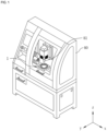
- FIG. 1 is a view schematically illustrating an application example of a dental blank according to an embodiment of the present disclosure
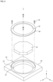
- FIG. 2 is an exploded perspective view schematically illustrating the dental blank according to an embodiment of the present disclosure
- FIG. 3 is a perspective view schematically illustrating a material portion of the dental blank according to an embodiment of the present disclosure
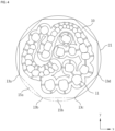
- FIG. 4 is a plan view schematically illustrating the material portion and a seating groove of the dental blank according to an embodiment of the present disclosure
- FIG. 5 is a cross-sectional view schematically illustrating the material portion and the seating groove of the dental blank according to an embodiment of the present disclosure
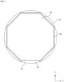
- FIGS. 6 and 7 are plan views schematically illustrating the material portion, a guard portion, and the seating groove of the dental blank according to an embodiment of the present disclosure
- FIG. 8 is a cross-sectional view schematically illustrating the material portion, the guard portion, and the seating groove of the dental blank according to an embodiment of the present disclosure
- FIG. 9 is a plan view schematically illustrating the material portion and the guard portion of the dental blank according to an embodiment of the present disclosure
- FIGS. 10 and 11 are cross-sectional views schematically illustrating the material portion and the guard portion of the dental blank according to an embodiment of the present disclosure.
- a dental blank 1 may be applied to an artificial tooth processing apparatus.
- the artificial tooth processing apparatus may be a processing apparatus 80 using a computer-aided design (CAD)/ a computer-aided manufacturing (CAM).
- the processing apparatus 80 using CAD/CAM may process the dental blank 1 by grinding, milling, cutting, etc.
- the dental blank 1 may include a material portion 10, a seating portion 20, and a fixing portion 40.
- the material portion 10 may be formed of at least one material selected from glass or glass-ceramic, polymer infiltrated glass, composite resin or hybrid material, unsintered or a partially sintered or a densely-sintered ceramic, and a metal or a metal alloy.
- the material portion 10 has characteristics such as high strength, thermal stability, and high corrosion resistance. Further, the material portion 10 with white or colored may be used alone or the material portion 10 with a mixture of white and colored may be used.
- the material portion 10 may be processed to be a dental prosthesis 11 by the processing apparatus 80 using CAD/CAM.
- CAD/CAM CAD/CAM
- a processing tool 81 of the processing apparatus 80 is operated based on data converted through an outer surface coordinate of a tooth model obtained by scanning, and the material portion 10 of the dental blank 1 is cut such that the material portion 10 is processed to be the dental prosthesis 11.
- the dental prosthesis 11 may refer to a dental restoration, a dental filler, or a dental cast that may be used in restoring a part of a tooth or may be used in replacing a lost tooth when a loss of a tooth occurs by a tooth fracture, or by damaging or defecting of a tooth caused by a cavity, or the like.
- the dental prosthesis 11 may be a crown, an inlay, an onlay, a veneer, a coping, a pontic, or a laminate that have various tooth forms.
- connection bar 12 that is connected to the dental prosthesis 11 may be additionally processed.
- the connection bar 12 may interconnect an inside of the material portion 10 and the dental prosthesis 11 that is processed, and the connection bar 12 may perform a function that allows the dental prosthesis 11 to be easily separated from the material portion 10.
- the material portion 10 may refer to a body that is machined by the processing apparatus 80 using CAD/CAM, or may refer to a body that is in a state in which the dental prosthesis 11 that is processed is included.
- the seating portion 20 is connected with the processing apparatus 80 using CAD/CAM, and may include a seating groove 21, a coupling groove 22, and coupling holes 23.
- the seating groove 21 may have a circular groove shape that is recessed toward an inside of the seating portion 20.
- the seating groove 21 may be a space in which the material portion 10 is seated. When the material portion 10 is positioned at the seating groove 21, a circumference of an inner side surface of the seating groove 21 may be in contact with outer side angles of the material portion 10.
- the coupling groove 22 may have a circular groove shape that is recessed toward the inside of the seating portion 20.
- the coupling groove 22 may be a space in which the fixing portion 40 is seated.
- the coupling holes 23 may have a hole shape that is formed toward the inside of the seating portion 20.
- the fixing portion 40 may include fasteners 41 and fastening holes 42.
- the fasteners 41 are fastening devices such as a bolt and so on, and may be connected to the coupling holes 23 with being in a state in which the fasteners 41 are inserted in the fastening holes 42 that penetrate the fixing portion 40.
- the fasteners 41 may be coupled to the coupling holes 23 by passing through the fastening holes 42. That is, since the fasteners 41 are fastened to the coupling holes 23 by bolting when the fixing portion 40 is in a state in which the fixing portion 40 is in contact with a portion of the material portion 10, the fixing portion 40 may fix the material portion 10 to the seating portion 20.
- the material portion 10 has a polygonal shape in a cross-section, and may include a plurality of outer contacting portions 13 that are positioned around an edge of the material portion 10.
- the outer contacting portions 13 may be formed to correspond to the polygonal shape of the material portion 10. For example, when the material portion 10 is formed in an octagonal shape, eight outer contacting portions 13 may be formed at the material portion 10.
- each of the outer contacting portions 13a, 13b, 13c, and 13d may be in contact with an inner side of the seating groove 21. Since the material portion 10 has the polygonal shape, each of the outer contacting portions 13a, 13b, 13c, and 13d may be in linear contact with an inner side surface of the seating groove 21 along an insertion direction that the material portion 10 is inserted into the seating groove 21. In other words, when the material portion 10 is inserted into the seating groove 21, as illustrated in the expanded circle in FIG. 5 , linear contacting portions 14 that are in linear contact along a z-axis direction may be formed between the inner surface of the seating groove 21 and the outer contacting portions 13a.
- a conventional workpiece is formed in a disc shape, and when the conventional workpiece is accommodated in a seating table, the entire of circular perimeter of the workpiece is in surface contact with and fixed to an inner surface of the seating table. In this state, when an external force is applied to the workpiece, the external force is spread to the entire of the workpiece along a wide surface contacting area between the workpiece and the seating table that is solid, so that the entire region of the workpiece may be broken.
- the material portion 10 of the present invention is formed in the polygonal shape, the outer contacting portions 13 and the seating groove 21 are in linear contact with each other when the material portion 10 is accommodated in the seating groove 21. That is, the linear contacting portions 14 that are relatively narrow are formed between the material portion 10 and the seating groove 21, so that an external force does not spread to the entire of the material portion 10 even if the external force is applied to the material portion 10. Therefore, the material portion 10 of the present invention is prevented from being entirely broken, so that the consumption of the material portion 10 caused by a crack may be reduced.
- tool entrance portions 15 may be formed between a space of the seating groove 21 and the outer contacting portions 13.
- the tool entrance portions 15 are separation spaces between the material portion 10 that is formed in the polygonal shape and the seating groove 21 that is formed in a circular shape.
- the tool entrance portions 15 may be spaces having a circular arc formed between a pair of outer contacting portions 13a and 13b and the inner surface of the seating groove 21.
- eight tool entrance portions 15 may be formed.
- the tool entrance portions 15 may be spaces in which the processing tool 81 of the processing apparatus 80 enters, or may be spaces in which the processing tool 81 is accommodated.
- a processing tool begins processing the workpiece from a top portion of the workpiece. Therefore, when the processing tool begins in contact with the top surface of the workpiece, the workpiece may be broken since a stress is concentrated on a contact surface instantaneously.
- a region where the workpiece is in close contact with the seating table or with a fixing table and a surrounding region are defined as a dead space that is a space impossible to process, so that a productivity of manufacturing a dental prosthesis is low.
- the dental blank 1 proposed in the present disclosure by forming the tool entrance portions 15 between the material portion 10 that is formed in the polygonal shape and the seating groove 21 that is formed in the circular shape, since a process begins in a state in which the processing tool 81 enters into a side surface of the material portion 10, an inserting load of the processing tool 81 is low and a stress concentration phenomenon may be prevented.
- the processing tool 81 begins processing from the tool entrance portions 15, a border region of the material portion 10 may be processed, so that the dead space of the material portion 10 may be reduced and production efficiency of the dental prosthesis 11 may increase.
- the material portion 10 may be a polygonal shape having four angles to 32 angles in a cross-section, and may preferably have an octagonal shape.
- the octagonal shape is not a mathematically perfect octagonal shape and should be understood to mean the octagonal shape when viewed in its entirety at a glance.
- the term "octagonal shape" may be understood to include the former and the latter.
- a diameter of the material portion 10 that is the longest diameter of the octagonal in a cross-section of the material portion 10 may be 50 mm or more, and may preferably be 80 mm to 150 mm.
- a thickness of the material portion 10, i.e., a height of the material portion 10 in the z-axis direction may be 5 mm or more. The thickness of the material portion 10 may be smaller than the diameter of the material portion 10.
- the material portion 10 may include a guard portion 30.
- the guard portion 30 may be positioned to be in contact with a side portion of the material portion 10.
- the guard portion 30 is manufactured of a material such as plastic, rubber, silicone, and so on, so that the guard portion 30 may relieve a stress, an impact, etc., that are transferred from the processing apparatus 80, thereby allowing the material portion 10 to be protected.
- the guard portion 30 may be attachable to and detachable from the material portion 10, and may be reused.
- the guard portion 30 may have an opening portion 31 at a side portion thereof. Since the opening portion 31 may be positioned to face the tool entrance portions 15, the material portion 10 may be processed directly through the opening portion 31 even if the processing tool 81 begins processing during in a state in which the processing tool 81 is positioned at the tool entrance portions 15.
- the guard portion 30 is formed in a circular shape, and may be positioned between the seating groove 21 and the material portion 10 by surrounding the side surface of the material portion 10. An outer side of the guard portion 30 may be in surface contact with the seating groove 21, and an inner side of the guard portion 30 may be in linear contact with the polygonal shape of the material portion 10. In this case, the guard portion 30 may protect the material portion 10 from an external force transferred from the processing apparatus 80.
- the guard portion 30 may be formed in a shape that correspond to the polygonal shape of the material portion 10.
- a cross-section of the guard portion 30 may be an octagonal shape.
- the guard portion 30 since the guard portion 30 is positioned to surround the side surface of the material portion 10, a processing vibration generated while the material portion 10 is processed may be attenuated, and it is possible to prevent the processing vibration from spreading to the processing apparatus 80.
- the guard portion 30 may be positioned to surround a portion of the side surface of the material portion 10. That is, a thickness of the guard portion 30, i.e., a height of the guard portion 30 in the z-axis direction may be smaller than the thickness of the material portion 10. In this case, when a cutting movement of the processing tool 81 is performed on the material portion 10, interference that occurs between the guard portion 30 and the processing tool 81 may be prevented.
- the guard portion 30 may be positioned at an upper portion of the material portion 10.
- the guard portion 30 is positioned between the material portion 10 and the fixing portion 40, and the material portion 10 may be protected from a fastening pressure that may be generated when the fixing portion 40 is fastened to the seating portion 20 by bolting.
- the guard portion 30 may be positioned at a lower portion of the material portion 10. In this case, by the guard portion 30 positioned between the material portion 10 and the seating portion 20, the guard portion 30 absorbs a stress generated when the processing tool 81 processes the material portion 10, so that the guard portion 30 may provide a cushioning effect to the material portion 10.
- the guard portion 30 may protect the material portion 10 by being in contact with the side portion of the material portion 10, and the guard portion 30 may be positioned at the side surface, the lower portion, or the upper portion of the material portion 10.
- the dental blank 1 according to the present disclosure including the guard portion 30 the material portion 10 does not directly contact the seating portion 20 or the fixing portion 40, so that the material portion 10 may be protected from an external force, thereby being capable of preventing the material portion 10 from breakage.
Landscapes
- Health & Medical Sciences (AREA)
- General Health & Medical Sciences (AREA)
- Dentistry (AREA)
- Epidemiology (AREA)
- Life Sciences & Earth Sciences (AREA)
- Animal Behavior & Ethology (AREA)
- Oral & Maxillofacial Surgery (AREA)
- Public Health (AREA)
- Veterinary Medicine (AREA)
- Engineering & Computer Science (AREA)
- Manufacturing & Machinery (AREA)
- Dental Tools And Instruments Or Auxiliary Dental Instruments (AREA)
- Dental Prosthetics (AREA)
- Dental Preparations (AREA)
Claims (5)
- Zahnrohling, umfassend:
einen Materialabschnitt (10), der in einen Einsatzabschnitt (20) eingeführt ist, der eine Einsatznut (21), die im Querschnitt kreisrund ausgebildet ist, umfasst, wobei der Materialabschnitt (10) eine Mehrzahl von äußeren Kontaktabschnitten (13) umfasst, die mit einer Innenseite des Einsatzabschnitts (20) in Kontakt stehen, und wobei der Materialabschnitt (10) im Querschnitt mehreckig ausgebildet ist, wobei die mehreckige Form sich von der kreisrunden Form unterscheidet,
wobei die Mehrzahl von äußeren Kontaktabschnitten (13) entlang einer Einführrichtung, in welcher der Materialabschnitt (10) in die Einsatznut (21) eingeführt ist, in linearem Kontakt mit einer inneren seitlichen Fläche des Einsatzabschnitts (20) steht und ein Werkzeugeingangsabschnitt (15), der ein Trennraum zwischen der Einsatznut (21) und dem Materialabschnitt (10) ist, aufgrund eines Formunterschieds zwischen der kreisrunden Form der Einsatznut (21) und der mehreckigen Form des Materialabschnitts (10) ausgebildet ist. - Zahnrohling nach Anspruch 1, wobei der Materialabschnitt (10) durch einen Schutzabschnitt (30) geschützt ist, der dazu positioniert ist, mit wenigstens einer Fläche aus einer oberen Fläche, einer unteren Fläche und einer seitlichen Fläche des Materialabschnitts (10) in Kontakt zu stehen, und ein Öffnungsabschnitt (31), der mit dem Werkzeugeingangsabschnitt (15), welcher der zwischen der Einsatznut (21) und dem Materialabschnitt (10) ausgebildeter Trennraum ist, verbunden ist, durch den Schutzabschnitt (30) ausgebildet ist.
- Zahnrohling nach Anspruch 2, wobei der Schutzabschnitt (30) dazu positioniert ist, eine seitliche Fläche des Materialabschnitts (10) zu umgeben.
- Zahnrohling nach Anspruch 2 oder 3, wobei der Schutzabschnitt (30) im Querschnitt mehreckig ausgebildet ist.
- Zahnrohling nach einem der vorangehenden Ansprüche, wobei der Einsatzabschnitt (20) eine Einsatznut (21) umfasst, in welcher der Materialabschnitt (10) eingesetzt ist, wobei die Einsatznut (21) im Querschnitt kreisrund ausgebildet ist.
Applications Claiming Priority (2)
| Application Number | Priority Date | Filing Date | Title |
|---|---|---|---|
| KR1020200105643A KR102432438B1 (ko) | 2020-08-21 | 2020-08-21 | 치과용 블랭크 |
| EP21184009.5A EP3957268B1 (de) | 2020-08-21 | 2021-07-06 | Zahnrohling |
Related Parent Applications (2)
| Application Number | Title | Priority Date | Filing Date |
|---|---|---|---|
| EP21184009.5A Division-Into EP3957268B1 (de) | 2020-08-21 | 2021-07-06 | Zahnrohling |
| EP21184009.5A Division EP3957268B1 (de) | 2020-08-21 | 2021-07-06 | Zahnrohling |
Publications (3)
| Publication Number | Publication Date |
|---|---|
| EP4233783A2 EP4233783A2 (de) | 2023-08-30 |
| EP4233783A3 EP4233783A3 (de) | 2023-11-01 |
| EP4233783B1 true EP4233783B1 (de) | 2025-01-22 |
Family
ID=76829335
Family Applications (2)
| Application Number | Title | Priority Date | Filing Date |
|---|---|---|---|
| EP23172695.1A Active EP4233783B1 (de) | 2020-08-21 | 2021-07-06 | Zahnrohling |
| EP21184009.5A Active EP3957268B1 (de) | 2020-08-21 | 2021-07-06 | Zahnrohling |
Family Applications After (1)
| Application Number | Title | Priority Date | Filing Date |
|---|---|---|---|
| EP21184009.5A Active EP3957268B1 (de) | 2020-08-21 | 2021-07-06 | Zahnrohling |
Country Status (8)
| Country | Link |
|---|---|
| US (2) | US20220054240A1 (de) |
| EP (2) | EP4233783B1 (de) |
| JP (2) | JP7330531B2 (de) |
| KR (2) | KR102432438B1 (de) |
| CN (1) | CN114073598B (de) |
| ES (2) | ES2957694T3 (de) |
| TW (1) | TWI813000B (de) |
| WO (1) | WO2022039437A1 (de) |
Families Citing this family (2)
| Publication number | Priority date | Publication date | Assignee | Title |
|---|---|---|---|---|
| KR102754580B1 (ko) * | 2022-06-29 | 2025-01-14 | 주식회사 하스 | 치아 보철물 제작용 블랭크 |
| KR102892821B1 (ko) * | 2023-03-08 | 2025-12-02 | 주식회사 하스 | 치아 보철물 제작용 블랭크 |
Family Cites Families (29)
| Publication number | Priority date | Publication date | Assignee | Title |
|---|---|---|---|---|
| JPH068085A (ja) * | 1992-04-02 | 1994-01-18 | Kenji Matsuda | 吸引式固定装置 |
| AU6755101A (en) * | 2000-06-22 | 2002-01-02 | 3M Espe Ag | Device for producing dental workpieces |
| ATE425715T1 (de) * | 2004-11-25 | 2009-04-15 | Heinrich Steger | Kopierfraseinrichtung zur herstellung von insbesondere zahntechnischen werkstucken |
| US20060172263A1 (en) | 2005-02-01 | 2006-08-03 | D4D Technologies, Lp | Mill blank |
| DE102006027397A1 (de) * | 2006-06-13 | 2007-12-20 | Amann Girrbach Gmbh | Werkstück zum Bearbeiten in spanabhebenden Bearbeitungsvorrichtungen |
| JP2008018501A (ja) * | 2006-07-13 | 2008-01-31 | Tdk Corp | ホルダ装置 |
| JP5576598B2 (ja) * | 2008-07-19 | 2014-08-20 | イボクラール ビバデント アクチェンゲゼルシャフト | 歯科用cad/camシステム用のアドレス可能なマトリックス/クラスターブランクおよびその最適化 |
| GB0902814D0 (en) * | 2009-02-19 | 2009-04-08 | Renishaw Plc | Billet and corresponding billet holder |
| DE102009044461B4 (de) * | 2009-11-06 | 2011-12-15 | Degudent Gmbh | Verfahren zum dimensionstreuen Sintern eines Formteils |
| DE202010001125U1 (de) * | 2010-01-22 | 2010-04-08 | Heimatec Gmbh | Vorrichtung zum Halten von zur Herstellung von Zahnersatzteilen dienenden Rohlingen |
| CN103003041A (zh) * | 2010-04-29 | 2013-03-27 | 牙科实验室铣床用品有限责任公司 | 用于由坯料生产产品的方法、系统和装置 |
| KR101382382B1 (ko) | 2011-04-25 | 2014-04-09 | 오명환 | 디스크 형태의 간접 수복용 컴포지트 레진 블록 |
| DE102012201744A1 (de) * | 2012-02-06 | 2013-08-08 | Wieland Dental + Technik Gmbh & Co. Kg | Werkstücksystem |
| US9675433B2 (en) * | 2012-11-29 | 2017-06-13 | Jensen Industries Inc. | Adapter for dental milling blank |
| KR101314192B1 (ko) | 2013-05-06 | 2013-10-02 | (주) 삼정디엠지코리아 | 다축 인공치아 가공장치용 고정지그 |
| DE102013210203A1 (de) | 2013-05-31 | 2014-12-04 | Christof Ellerbrock | Adapter zur Ausbildung einer Rohlingsanordnung sowie Rohlingsanordnung |
| DE202013103515U1 (de) * | 2013-08-05 | 2013-09-12 | Ivoclar Vivadent Ag | Rohlingaufnahme sowie Dental-Fräsmaschine |
| JP5885731B2 (ja) * | 2013-12-24 | 2016-03-15 | ローランドディー.ジー.株式会社 | ワーク保持装置 |
| JP2014168707A (ja) | 2014-05-19 | 2014-09-18 | Ivoclar Vivadent Ag | 歯科用cad/camシステム用のアドレス可能なマトリックス/クラスターブランクおよびその最適化 |
| DE102015100666A1 (de) * | 2015-01-19 | 2016-07-21 | Dentsply International Inc. | Halterung für einen Rohling |
| CN107405186B (zh) | 2015-03-19 | 2021-06-18 | 可乐丽则武齿科株式会社 | 被加工单元及其制造方法 |
| EP3272306B1 (de) * | 2015-03-19 | 2020-06-10 | Kuraray Noritake Dental Inc. | Werkstückeinheit und verfahren zur herstellung davon |
| CN107427346B (zh) * | 2015-03-19 | 2021-09-24 | 可乐丽则武齿科株式会社 | 被加工单元 |
| CN105252298A (zh) * | 2015-10-30 | 2016-01-20 | 昆山洺九机电有限公司 | 一种板式工件定位工装 |
| FR3044890B1 (fr) | 2015-12-10 | 2018-04-27 | Societe De Recherches Techniques Dentaires - Rtd | Disque usinable par cfao pour la fabrication d'inlay core fibres |
| US11858083B2 (en) | 2017-03-09 | 2024-01-02 | Global Dental Science, LLC | Dental blank positioning device |
| KR101963519B1 (ko) * | 2017-12-21 | 2019-07-31 | 주식회사 지르코리아 | 세라믹 계열의 인체 삽입용 임플란트 가공을 위한 지그 장치 |
| KR101997032B1 (ko) * | 2018-06-13 | 2019-10-17 | 주식회사 피스티스 | 치과 수복물 가공용 가공테이블조립체 및 이를 이용한 치과 수복물 가공방법 |
| CN109620441B (zh) * | 2019-02-27 | 2024-05-24 | 爱迪特(秦皇岛)科技股份有限公司 | 一种夹具及义齿加工设备 |
-
2020
- 2020-08-21 KR KR1020200105643A patent/KR102432438B1/ko active Active
-
2021
- 2021-07-06 EP EP23172695.1A patent/EP4233783B1/de active Active
- 2021-07-06 ES ES21184009T patent/ES2957694T3/es active Active
- 2021-07-06 US US17/368,440 patent/US20220054240A1/en not_active Abandoned
- 2021-07-06 ES ES23172695T patent/ES3010698T3/es active Active
- 2021-07-06 EP EP21184009.5A patent/EP3957268B1/de active Active
- 2021-07-07 JP JP2021112675A patent/JP7330531B2/ja active Active
- 2021-07-13 CN CN202110789568.6A patent/CN114073598B/zh active Active
- 2021-08-11 WO PCT/KR2021/010642 patent/WO2022039437A1/ko not_active Ceased
- 2021-08-16 TW TW110130173A patent/TWI813000B/zh active
-
2022
- 2022-07-12 KR KR1020220085701A patent/KR102504212B1/ko active Active
-
2023
- 2023-04-17 US US18/301,313 patent/US12274591B2/en active Active
- 2023-08-02 JP JP2023125929A patent/JP7671084B2/ja active Active
Also Published As
| Publication number | Publication date |
|---|---|
| EP3957268B1 (de) | 2023-06-28 |
| TWI813000B (zh) | 2023-08-21 |
| WO2022039437A1 (ko) | 2022-02-24 |
| ES3010698T3 (en) | 2025-04-04 |
| JP2022035995A (ja) | 2022-03-04 |
| JP2023145659A (ja) | 2023-10-11 |
| JP7330531B2 (ja) | 2023-08-22 |
| EP4233783A2 (de) | 2023-08-30 |
| JP7671084B2 (ja) | 2025-05-01 |
| US20220054240A1 (en) | 2022-02-24 |
| CN114073598A (zh) | 2022-02-22 |
| CN114073598B (zh) | 2024-07-23 |
| KR102432438B1 (ko) | 2022-08-16 |
| EP3957268A1 (de) | 2022-02-23 |
| US12274591B2 (en) | 2025-04-15 |
| ES2957694T3 (es) | 2024-01-24 |
| KR20220103895A (ko) | 2022-07-25 |
| KR102504212B1 (ko) | 2023-02-28 |
| US20230248492A1 (en) | 2023-08-10 |
| EP4233783A3 (de) | 2023-11-01 |
| KR20220023651A (ko) | 2022-03-02 |
| TW202211903A (zh) | 2022-04-01 |
Similar Documents
| Publication | Publication Date | Title |
|---|---|---|
| US12274591B2 (en) | Dental blank | |
| CN1116950C (zh) | 切削刀具和切削刀片 | |
| KR101630669B1 (ko) | 임플란트용 어버트먼트와 크라운에 결합구조 | |
| KR20040014445A (ko) | 절삭 인서트 및 절삭 인서트를 제조하는 방법 | |
| KR100850660B1 (ko) | 인덱서블 커팅 인서트와 이를 구비한 절삭 공구 및인덱서블 커팅 인서트의 제조 방법 | |
| US10850334B2 (en) | Mold for resin sealing a semiconductor chip, and semiconductor device having resin-sealed semiconductor chip | |
| KR20160006385A (ko) | 스캔바디 기능을 구비한 힐링어버트먼트 | |
| AU2004292756B2 (en) | Method for producing a molded piece | |
| CN107921556B (zh) | 切削刀具、刀具本体和用于生产刀具本体的方法 | |
| US20070290385A1 (en) | Blank for a Tooth Replacement Part and Method of Producing a Tooth Replacement Part | |
| KR20240002539A (ko) | 치아 보철물 제작용 블랭크 | |
| KR101997032B1 (ko) | 치과 수복물 가공용 가공테이블조립체 및 이를 이용한 치과 수복물 가공방법 | |
| JP2021115274A (ja) | 加工用ブロック | |
| KR20240137393A (ko) | 치아 보철물 제작용 블랭크 | |
| JPH10263914A (ja) | ボールエンドミル | |
| JP6093901B1 (ja) | 全周に亘らない溝を有する歯科用cadcam用被切削体 | |
| KR200482050Y1 (ko) | 다양한 종류의 지그에 사용될 수 있는 임플란트용 어버트먼트 | |
| JP2011051029A (ja) | 切削工具 | |
| KR102599233B1 (ko) | 임플란트 크라운 cad 전용 라이브러리 및 크라운 가공용 툴 | |
| JP2703725B2 (ja) | 冷間圧造工具 | |
| KR102242487B1 (ko) | 밴드타입 크라운 | |
| KR100422658B1 (ko) | 클러치 기어 단조용 금형 | |
| SU1379045A1 (ru) | Способ изготовлени режущего инструмента | |
| KR20250132742A (ko) | 근관 포스트 및 그 제조방법 | |
| CN206185163U (zh) | 一种车铣两用刀片 |
Legal Events
| Date | Code | Title | Description |
|---|---|---|---|
| PUAI | Public reference made under article 153(3) epc to a published international application that has entered the european phase |
Free format text: ORIGINAL CODE: 0009012 |
|
| STAA | Information on the status of an ep patent application or granted ep patent |
Free format text: STATUS: THE APPLICATION HAS BEEN PUBLISHED |
|
| AC | Divisional application: reference to earlier application |
Ref document number: 3957268 Country of ref document: EP Kind code of ref document: P |
|
| AK | Designated contracting states |
Kind code of ref document: A2 Designated state(s): AL AT BE BG CH CY CZ DE DK EE ES FI FR GB GR HR HU IE IS IT LI LT LU LV MC MK MT NL NO PL PT RO RS SE SI SK SM TR |
|
| PUAL | Search report despatched |
Free format text: ORIGINAL CODE: 0009013 |
|
| AK | Designated contracting states |
Kind code of ref document: A3 Designated state(s): AL AT BE BG CH CY CZ DE DK EE ES FI FR GB GR HR HU IE IS IT LI LT LU LV MC MK MT NL NO PL PT RO RS SE SI SK SM TR |
|
| RIC1 | Information provided on ipc code assigned before grant |
Ipc: A61C 13/00 20060101AFI20230922BHEP |
|
| STAA | Information on the status of an ep patent application or granted ep patent |
Free format text: STATUS: REQUEST FOR EXAMINATION WAS MADE |
|
| 17P | Request for examination filed |
Effective date: 20240430 |
|
| RBV | Designated contracting states (corrected) |
Designated state(s): AL AT BE BG CH CY CZ DE DK EE ES FI FR GB GR HR HU IE IS IT LI LT LU LV MC MK MT NL NO PL PT RO RS SE SI SK SM TR |
|
| GRAP | Despatch of communication of intention to grant a patent |
Free format text: ORIGINAL CODE: EPIDOSNIGR1 |
|
| STAA | Information on the status of an ep patent application or granted ep patent |
Free format text: STATUS: GRANT OF PATENT IS INTENDED |
|
| INTG | Intention to grant announced |
Effective date: 20240916 |
|
| GRAS | Grant fee paid |
Free format text: ORIGINAL CODE: EPIDOSNIGR3 |
|
| GRAA | (expected) grant |
Free format text: ORIGINAL CODE: 0009210 |
|
| STAA | Information on the status of an ep patent application or granted ep patent |
Free format text: STATUS: THE PATENT HAS BEEN GRANTED |
|
| AC | Divisional application: reference to earlier application |
Ref document number: 3957268 Country of ref document: EP Kind code of ref document: P |
|
| AK | Designated contracting states |
Kind code of ref document: B1 Designated state(s): AL AT BE BG CH CY CZ DE DK EE ES FI FR GB GR HR HU IE IS IT LI LT LU LV MC MK MT NL NO PL PT RO RS SE SI SK SM TR |
|
| REG | Reference to a national code |
Ref country code: GB Ref legal event code: FG4D |
|
| REG | Reference to a national code |
Ref country code: CH Ref legal event code: EP |
|
| REG | Reference to a national code |
Ref country code: IE Ref legal event code: FG4D |
|
| REG | Reference to a national code |
Ref country code: DE Ref legal event code: R096 Ref document number: 602021025271 Country of ref document: DE |
|
| P01 | Opt-out of the competence of the unified patent court (upc) registered |
Free format text: CASE NUMBER: APP_3266/2025 Effective date: 20250121 |
|
| REG | Reference to a national code |
Ref country code: ES Ref legal event code: FG2A Ref document number: 3010698 Country of ref document: ES Kind code of ref document: T3 Effective date: 20250404 |
|
| REG | Reference to a national code |
Ref country code: NL Ref legal event code: MP Effective date: 20250122 |
|
| PG25 | Lapsed in a contracting state [announced via postgrant information from national office to epo] |
Ref country code: NL Free format text: LAPSE BECAUSE OF FAILURE TO SUBMIT A TRANSLATION OF THE DESCRIPTION OR TO PAY THE FEE WITHIN THE PRESCRIBED TIME-LIMIT Effective date: 20250122 |
|
| PG25 | Lapsed in a contracting state [announced via postgrant information from national office to epo] |
Ref country code: RS Free format text: LAPSE BECAUSE OF FAILURE TO SUBMIT A TRANSLATION OF THE DESCRIPTION OR TO PAY THE FEE WITHIN THE PRESCRIBED TIME-LIMIT Effective date: 20250422 |
|
| PG25 | Lapsed in a contracting state [announced via postgrant information from national office to epo] |
Ref country code: FI Free format text: LAPSE BECAUSE OF FAILURE TO SUBMIT A TRANSLATION OF THE DESCRIPTION OR TO PAY THE FEE WITHIN THE PRESCRIBED TIME-LIMIT Effective date: 20250122 |
|
| PG25 | Lapsed in a contracting state [announced via postgrant information from national office to epo] |
Ref country code: PL Free format text: LAPSE BECAUSE OF FAILURE TO SUBMIT A TRANSLATION OF THE DESCRIPTION OR TO PAY THE FEE WITHIN THE PRESCRIBED TIME-LIMIT Effective date: 20250122 |
|
| REG | Reference to a national code |
Ref country code: LT Ref legal event code: MG9D |
|
| PG25 | Lapsed in a contracting state [announced via postgrant information from national office to epo] |
Ref country code: IS Free format text: LAPSE BECAUSE OF FAILURE TO SUBMIT A TRANSLATION OF THE DESCRIPTION OR TO PAY THE FEE WITHIN THE PRESCRIBED TIME-LIMIT Effective date: 20250522 Ref country code: NO Free format text: LAPSE BECAUSE OF FAILURE TO SUBMIT A TRANSLATION OF THE DESCRIPTION OR TO PAY THE FEE WITHIN THE PRESCRIBED TIME-LIMIT Effective date: 20250422 |
|
| REG | Reference to a national code |
Ref country code: AT Ref legal event code: MK05 Ref document number: 1760891 Country of ref document: AT Kind code of ref document: T Effective date: 20250122 |
|
| PG25 | Lapsed in a contracting state [announced via postgrant information from national office to epo] |
Ref country code: HR Free format text: LAPSE BECAUSE OF FAILURE TO SUBMIT A TRANSLATION OF THE DESCRIPTION OR TO PAY THE FEE WITHIN THE PRESCRIBED TIME-LIMIT Effective date: 20250122 |
|
| PG25 | Lapsed in a contracting state [announced via postgrant information from national office to epo] |
Ref country code: LV Free format text: LAPSE BECAUSE OF FAILURE TO SUBMIT A TRANSLATION OF THE DESCRIPTION OR TO PAY THE FEE WITHIN THE PRESCRIBED TIME-LIMIT Effective date: 20250122 Ref country code: PT Free format text: LAPSE BECAUSE OF FAILURE TO SUBMIT A TRANSLATION OF THE DESCRIPTION OR TO PAY THE FEE WITHIN THE PRESCRIBED TIME-LIMIT Effective date: 20250522 |
|
| PG25 | Lapsed in a contracting state [announced via postgrant information from national office to epo] |
Ref country code: BG Free format text: LAPSE BECAUSE OF FAILURE TO SUBMIT A TRANSLATION OF THE DESCRIPTION OR TO PAY THE FEE WITHIN THE PRESCRIBED TIME-LIMIT Effective date: 20250122 Ref country code: GR Free format text: LAPSE BECAUSE OF FAILURE TO SUBMIT A TRANSLATION OF THE DESCRIPTION OR TO PAY THE FEE WITHIN THE PRESCRIBED TIME-LIMIT Effective date: 20250423 |
|
| PG25 | Lapsed in a contracting state [announced via postgrant information from national office to epo] |
Ref country code: AT Free format text: LAPSE BECAUSE OF FAILURE TO SUBMIT A TRANSLATION OF THE DESCRIPTION OR TO PAY THE FEE WITHIN THE PRESCRIBED TIME-LIMIT Effective date: 20250122 |
|
| PG25 | Lapsed in a contracting state [announced via postgrant information from national office to epo] |
Ref country code: SE Free format text: LAPSE BECAUSE OF FAILURE TO SUBMIT A TRANSLATION OF THE DESCRIPTION OR TO PAY THE FEE WITHIN THE PRESCRIBED TIME-LIMIT Effective date: 20250122 |
|
| PG25 | Lapsed in a contracting state [announced via postgrant information from national office to epo] |
Ref country code: SM Free format text: LAPSE BECAUSE OF FAILURE TO SUBMIT A TRANSLATION OF THE DESCRIPTION OR TO PAY THE FEE WITHIN THE PRESCRIBED TIME-LIMIT Effective date: 20250122 |
|
| PGFP | Annual fee paid to national office [announced via postgrant information from national office to epo] |
Ref country code: ES Payment date: 20250819 Year of fee payment: 5 |
|
| PG25 | Lapsed in a contracting state [announced via postgrant information from national office to epo] |
Ref country code: DK Free format text: LAPSE BECAUSE OF FAILURE TO SUBMIT A TRANSLATION OF THE DESCRIPTION OR TO PAY THE FEE WITHIN THE PRESCRIBED TIME-LIMIT Effective date: 20250122 |
|
| PGFP | Annual fee paid to national office [announced via postgrant information from national office to epo] |
Ref country code: DE Payment date: 20250731 Year of fee payment: 5 |
|
| PGFP | Annual fee paid to national office [announced via postgrant information from national office to epo] |
Ref country code: IT Payment date: 20250728 Year of fee payment: 5 |
|
| PGFP | Annual fee paid to national office [announced via postgrant information from national office to epo] |
Ref country code: GB Payment date: 20250822 Year of fee payment: 5 |
|
| PGFP | Annual fee paid to national office [announced via postgrant information from national office to epo] |
Ref country code: FR Payment date: 20250723 Year of fee payment: 5 |
|
| PGFP | Annual fee paid to national office [announced via postgrant information from national office to epo] |
Ref country code: CH Payment date: 20250822 Year of fee payment: 5 |
|
| PG25 | Lapsed in a contracting state [announced via postgrant information from national office to epo] |
Ref country code: CZ Free format text: LAPSE BECAUSE OF FAILURE TO SUBMIT A TRANSLATION OF THE DESCRIPTION OR TO PAY THE FEE WITHIN THE PRESCRIBED TIME-LIMIT Effective date: 20250122 Ref country code: EE Free format text: LAPSE BECAUSE OF FAILURE TO SUBMIT A TRANSLATION OF THE DESCRIPTION OR TO PAY THE FEE WITHIN THE PRESCRIBED TIME-LIMIT Effective date: 20250122 |
|
| REG | Reference to a national code |
Ref country code: DE Ref legal event code: R097 Ref document number: 602021025271 Country of ref document: DE |
|
| PG25 | Lapsed in a contracting state [announced via postgrant information from national office to epo] |
Ref country code: RO Free format text: LAPSE BECAUSE OF FAILURE TO SUBMIT A TRANSLATION OF THE DESCRIPTION OR TO PAY THE FEE WITHIN THE PRESCRIBED TIME-LIMIT Effective date: 20250122 |
|
| PG25 | Lapsed in a contracting state [announced via postgrant information from national office to epo] |
Ref country code: SK Free format text: LAPSE BECAUSE OF FAILURE TO SUBMIT A TRANSLATION OF THE DESCRIPTION OR TO PAY THE FEE WITHIN THE PRESCRIBED TIME-LIMIT Effective date: 20250122 |
|
| PLBE | No opposition filed within time limit |
Free format text: ORIGINAL CODE: 0009261 |
|
| STAA | Information on the status of an ep patent application or granted ep patent |
Free format text: STATUS: NO OPPOSITION FILED WITHIN TIME LIMIT |
|
| 26N | No opposition filed |
Effective date: 20251023 |
|
| PG25 | Lapsed in a contracting state [announced via postgrant information from national office to epo] |
Ref country code: LU Free format text: LAPSE BECAUSE OF NON-PAYMENT OF DUE FEES Effective date: 20250706 |
|
| REG | Reference to a national code |
Ref country code: BE Ref legal event code: MM Effective date: 20250731 |
|
| PG25 | Lapsed in a contracting state [announced via postgrant information from national office to epo] |
Ref country code: BE Free format text: LAPSE BECAUSE OF NON-PAYMENT OF DUE FEES Effective date: 20250731 |