EP4232295B1 - Verfahren zum drucken von leiterbahnen auf ein objekt und zugehöriges elektronisches funktionalisierungsverfahren - Google Patents
Verfahren zum drucken von leiterbahnen auf ein objekt und zugehöriges elektronisches funktionalisierungsverfahren Download PDFInfo
- Publication number
- EP4232295B1 EP4232295B1 EP21794359.6A EP21794359A EP4232295B1 EP 4232295 B1 EP4232295 B1 EP 4232295B1 EP 21794359 A EP21794359 A EP 21794359A EP 4232295 B1 EP4232295 B1 EP 4232295B1
- Authority
- EP
- European Patent Office
- Prior art keywords
- robot
- arm
- conductive track
- printhead
- printing
- Prior art date
- Legal status (The legal status is an assumption and is not a legal conclusion. Google has not performed a legal analysis and makes no representation as to the accuracy of the status listed.)
- Active
Links
Images


Classifications
-
- B—PERFORMING OPERATIONS; TRANSPORTING
- B41—PRINTING; LINING MACHINES; TYPEWRITERS; STAMPS
- B41J—TYPEWRITERS; SELECTIVE PRINTING MECHANISMS, i.e. MECHANISMS PRINTING OTHERWISE THAN FROM A FORME; CORRECTION OF TYPOGRAPHICAL ERRORS
- B41J3/00—Typewriters or selective printing or marking mechanisms characterised by the purpose for which they are constructed
- B41J3/407—Typewriters or selective printing or marking mechanisms characterised by the purpose for which they are constructed for marking on special material
- B41J3/4073—Printing on three-dimensional objects not being in sheet or web form, e.g. spherical or cubic objects
-
- B—PERFORMING OPERATIONS; TRANSPORTING
- B05—SPRAYING OR ATOMISING IN GENERAL; APPLYING FLUENT MATERIALS TO SURFACES, IN GENERAL
- B05B—SPRAYING APPARATUS; ATOMISING APPARATUS; NOZZLES
- B05B12/00—Arrangements for controlling delivery; Arrangements for controlling the spray area
-
- B—PERFORMING OPERATIONS; TRANSPORTING
- B05—SPRAYING OR ATOMISING IN GENERAL; APPLYING FLUENT MATERIALS TO SURFACES, IN GENERAL
- B05B—SPRAYING APPARATUS; ATOMISING APPARATUS; NOZZLES
- B05B13/00—Machines or plants for applying liquids or other fluent materials to surfaces of objects or other work by spraying, not covered by groups B05B1/00 - B05B11/00
- B05B13/02—Means for supporting work; Arrangement or mounting of spray heads; Adaptation or arrangement of means for feeding work
- B05B13/04—Means for supporting work; Arrangement or mounting of spray heads; Adaptation or arrangement of means for feeding work the spray heads being moved during spraying operation
- B05B13/0431—Means for supporting work; Arrangement or mounting of spray heads; Adaptation or arrangement of means for feeding work the spray heads being moved during spraying operation with spray heads moved by robots or articulated arms, e.g. for applying liquid or other fluent material to three-dimensional [3D] surfaces
-
- B—PERFORMING OPERATIONS; TRANSPORTING
- B25—HAND TOOLS; PORTABLE POWER-DRIVEN TOOLS; MANIPULATORS
- B25J—MANIPULATORS; CHAMBERS PROVIDED WITH MANIPULATION DEVICES
- B25J11/00—Manipulators not otherwise provided for
-
- B—PERFORMING OPERATIONS; TRANSPORTING
- B25—HAND TOOLS; PORTABLE POWER-DRIVEN TOOLS; MANIPULATORS
- B25J—MANIPULATORS; CHAMBERS PROVIDED WITH MANIPULATION DEVICES
- B25J11/00—Manipulators not otherwise provided for
- B25J11/0075—Manipulators for painting or coating
-
- B—PERFORMING OPERATIONS; TRANSPORTING
- B25—HAND TOOLS; PORTABLE POWER-DRIVEN TOOLS; MANIPULATORS
- B25J—MANIPULATORS; CHAMBERS PROVIDED WITH MANIPULATION DEVICES
- B25J19/00—Accessories fitted to manipulators, e.g. for monitoring, for viewing; Safety devices combined with or specially adapted for use in connection with manipulators
- B25J19/02—Sensing devices
- B25J19/021—Optical sensing devices
- B25J19/022—Optical sensing devices using lasers
-
- B—PERFORMING OPERATIONS; TRANSPORTING
- B33—ADDITIVE MANUFACTURING TECHNOLOGY
- B33Y—ADDITIVE MANUFACTURING, i.e. MANUFACTURING OF THREE-DIMENSIONAL [3D] OBJECTS BY ADDITIVE DEPOSITION, ADDITIVE AGGLOMERATION OR ADDITIVE LAYERING, e.g. BY 3D PRINTING, STEREOLITHOGRAPHY OR SELECTIVE LASER SINTERING
- B33Y30/00—Apparatus for additive manufacturing; Details thereof or accessories therefor
-
- H—ELECTRICITY
- H05—ELECTRIC TECHNIQUES NOT OTHERWISE PROVIDED FOR
- H05K—PRINTED CIRCUITS; CASINGS OR CONSTRUCTIONAL DETAILS OF ELECTRIC APPARATUS; MANUFACTURE OF ASSEMBLAGES OF ELECTRICAL COMPONENTS
- H05K3/00—Apparatus or processes for manufacturing printed circuits
- H05K3/10—Apparatus or processes for manufacturing printed circuits in which conductive material is applied to the insulating support in such a manner as to form the desired conductive pattern
- H05K3/102—Apparatus or processes for manufacturing printed circuits in which conductive material is applied to the insulating support in such a manner as to form the desired conductive pattern by bonding of conductive powder, i.e. metallic powder
-
- B—PERFORMING OPERATIONS; TRANSPORTING
- B33—ADDITIVE MANUFACTURING TECHNOLOGY
- B33Y—ADDITIVE MANUFACTURING, i.e. MANUFACTURING OF THREE-DIMENSIONAL [3D] OBJECTS BY ADDITIVE DEPOSITION, ADDITIVE AGGLOMERATION OR ADDITIVE LAYERING, e.g. BY 3D PRINTING, STEREOLITHOGRAPHY OR SELECTIVE LASER SINTERING
- B33Y80/00—Products made by additive manufacturing
-
- H—ELECTRICITY
- H05—ELECTRIC TECHNIQUES NOT OTHERWISE PROVIDED FOR
- H05K—PRINTED CIRCUITS; CASINGS OR CONSTRUCTIONAL DETAILS OF ELECTRIC APPARATUS; MANUFACTURE OF ASSEMBLAGES OF ELECTRICAL COMPONENTS
- H05K2201/00—Indexing scheme relating to printed circuits covered by H05K1/00
- H05K2201/09—Shape and layout
- H05K2201/09818—Shape or layout details not covered by a single group of H05K2201/09009 - H05K2201/09809
- H05K2201/0999—Circuit printed on or in housing, e.g. housing as PCB; Circuit printed on the case of a component; PCB affixed to housing
-
- H—ELECTRICITY
- H05—ELECTRIC TECHNIQUES NOT OTHERWISE PROVIDED FOR
- H05K—PRINTED CIRCUITS; CASINGS OR CONSTRUCTIONAL DETAILS OF ELECTRIC APPARATUS; MANUFACTURE OF ASSEMBLAGES OF ELECTRICAL COMPONENTS
- H05K3/00—Apparatus or processes for manufacturing printed circuits
- H05K3/10—Apparatus or processes for manufacturing printed circuits in which conductive material is applied to the insulating support in such a manner as to form the desired conductive pattern
- H05K3/12—Apparatus or processes for manufacturing printed circuits in which conductive material is applied to the insulating support in such a manner as to form the desired conductive pattern using thick film techniques, e.g. printing techniques to apply the conductive material or similar techniques for applying conductive paste or ink patterns
- H05K3/1241—Apparatus or processes for manufacturing printed circuits in which conductive material is applied to the insulating support in such a manner as to form the desired conductive pattern using thick film techniques, e.g. printing techniques to apply the conductive material or similar techniques for applying conductive paste or ink patterns by ink-jet printing or drawing by dispensing
- H05K3/125—Apparatus or processes for manufacturing printed circuits in which conductive material is applied to the insulating support in such a manner as to form the desired conductive pattern using thick film techniques, e.g. printing techniques to apply the conductive material or similar techniques for applying conductive paste or ink patterns by ink-jet printing or drawing by dispensing by ink-jet printing
Definitions
- the present invention relates to the field of systems and methods for printing a conductive track on the surface of an object. It finds particularly advantageous application in the field of electronic functionalization of objects regardless of their geometry.
- a disadvantage of the system according to the patent document WO 2016/097932 is that it is not, or is at least poorly, suited to implementation on a production line. It would actually require a stoppage of the production line at least to change the object to be functionalized. In addition, to ensure the positioning accuracy of the conductive tracks, it would be necessary to know precisely how the object was grasped by the robot, which presents certain difficulties, relatively incompatible with the desired level of industrialization. Furthermore, the system according to the patent document WO 2016/097932 is limited to objects of size, shape, and especially weight, compatible with the handling capabilities of the robot. Another example of a printing process is given in the patent document EP 3235355 A1 .
- An object of the present invention is therefore to propose a method for printing a conductive track on the surface of an object which makes it possible to overcome at least one of the aforementioned drawbacks.
- Another object of the present invention is to propose a method for electronically functionalizing an object making it possible to reduce the time between design and manufacturing of prototypes, or even pre-series, of the object.
- a method for printing at least one conductive track on the surface of an object.
- the method uses at least one robot arm having several degrees of freedom and at least one conductive ink print head. At least a portion of the object is arranged in a workspace of said at least one robot.
- the printing method as introduced above may further have at least any one of the following features which may be taken separately or in combination.
- the object is a three-dimensional object.
- the method further comprises, following the step of carrying out the 3D scan of the object and before the step of constructing said digital model, a step consisting of identifying the position of the object relative to a reference frame (TCP for “Tool Center Point”) of said at least one robot.
- a reference frame TCP for “Tool Center Point”
- the drawing of the conductive track is performed directly on the constructed digital model or is generated by projecting a two-dimensional (2D) digital model of the conductive track onto the constructed digital model.
- said at least one robot comprises at least one six-axis articulated arm robot.
- the scanner includes a laser triangulation sensor.
- the laser triangulation sensor may include at least one of a laser spot sensor and a laser line sensor.
- the printing step also includes the implementation of contact dosing systems (pneumatic or volumetric extrusion through needles) or contactless (piezoelectric jet of ink drops).
- the method further comprises a step of treating at least one conductive track using a spray valve mounted on a robot arm which ensures its movement relative to the object, if necessary following the previously generated trajectory.
- the method further comprises, prior to the step of performing the 3D scan, an initialization step comprising the generation of a digital model of at least one of the scanner, the print head and a possible associated dosing system, a pick-and-place machine with integrated vision device and a spray valve.
- At least two of the scanner, the print head and a possible associated dosing system, a pick-and-place machine with integrated vision device and a spray valve are mounted on the same robot arm.
- At least two of the scanner, the print head and a possible associated dosing system, a pick-and-place machine with integrated vision device and a spray valve are mounted on robot arms that are different from each other.
- a conveyor can be provided which is configured to convey the object from a workspace of a first robot to a workspace of another robot.
- at least two robots are arranged at different, and possibly successive, stations of the same production line.
- Another aspect of the invention relates to a computer program product comprising instructions, which when carried out by at least one processor, executes at least the steps of the printing method as introduced above.
- Another aspect of the invention relates to a computer program product comprising instructions, which when carried out by at least one processor, executes at least the steps of the electronic functionalization method as introduced above.
- a pick-and-place machine is a machine for picking and positioning.
- printed circuit means a set of conductive tracks arranged together on a support, here materialized by the object, and allowing a set of electronic components to be electrically connected together, with the aim of creating an electronic circuit.
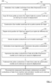
- an embodiment of the first aspect of the invention provides for the printing 100 of conductive tracks 10 on the surface of an object 1 by using an arm robot 2 having several degrees of freedom and at least at least one conductive ink print head 3.
- the robot 2 may more particularly be a six-axis articulated arm robot. Such a robot is advantageously suitable for controlled and routine industrial use.
- object 1 which is placed in a workspace of robot 2; the tools necessary for printing are carried by robot 2 which ensures their movement relative to object 1.
- the object and more particularly the surface of the object to be scanned 110 is preferably opaque or made opaque. It will also be noted that the object can advantageously be a so-called multi-material object.
- an embodiment of a second aspect of the invention provides for continuing the printing method 100 according to its first aspect by a step 160 of placing electronic components 12, in predefined locations of a printed circuit 11 consisting of a plurality of conductive tracks 10, using a “pick-and-place” machine 6, with integrated vision device 60, mounted on the arm of the robot 2, so as to electronically functionalize the object 1.
- the object 1 remains in the same position during the printing process 100 and, where appropriate, the functionalization process 200.
- object 1 can be of any weight. Indeed, object 1 rests for example on a platform, defining the workspace of robot 2, which can be adapted to receive an object of any weight. Object 1 can also be of any shape. Since the scanner is configured to perform a 3D scan, the object is not actually limited to a 2D shape; the scanned part of object 1 can have a curved surface. Furthermore, the 3D scan may only concern a part of object 1. As long as the part of object 1 concerned by the 3D scan enters the workspace of the robot, object 1 can be of any dimensions.
- the object must necessarily be of reduced weight to be able to be moved by the robot (a six-axis arm robot can generally move objects weighing at most 3 kg), of a shape allowing it to be gripped by the robot, and of dimensions limited by those of the robot's workspace.
- the methods 100 and 200 according to the invention have the advantage, unlike the printing system described in the document WO 2016/097932 , not to require stopping the production line for each change of object to be functionalized.
- Two or three robots 2 may even, according to the invention, be provided to act simultaneously or successively on the object 1.
- at least two robots 2 are arranged at different stations from each other, and possibly successive, of the same production line.
- the use of several robots 2 each carrying one or more of the tools necessary for printing 100 and where appropriate for functionalization 200 may be provided jointly with that of a conveyor configured to convey the object from a workspace of a first robot to a workspace of a following robot along the production line.
- the present invention also makes it possible to overcome difficulties inherent in the printing system described in the document WO 2016/097932 , of defining the way in which the robot grasped the object. Indeed, since the object 1 can remain, during the methods 100 and 200 according to the invention, in a fixed position, it may be sufficient to ensure that the initial positioning of the object 1 is known with sufficient precision to implement the invention. If necessary, a step may be provided consisting of identifying 125 the position of the object 1 relative to a reference frame (TCP for “Tool Center Point”) of the robot 2, in particular following the 3D scan 110 and before the construction step (120) of said digital model, so as to ensure that the steps of the process carried out using the CAD software are carried out with precision. Indeed, the calibration of the robot 2 and the automatic positioning of the robot 2 relative to the object 1 are, by this location step 125, made possible, even if the positioning of the object 1 in the workspace of the robot 2 is not predefined.
- TCP Tool Center Point
- Another advantage of the printing method according to the first aspect of the invention lies in the fact that it is compatible with a production of the drawing 130 of the conductive track 10 either directly on the constructed digital model 120, or by projection of a 2D digital model of the conductive track 10 onto the constructed digital model 120.
- an initialization step comprising the generation 105 of a digital model of at least one of the print head 3 and a possible associated dosing system 30, the scanner 4, a spray valve 5, and a pick-and-place machine 6 with integrated vision device 60.
- the distance of each tool at each instant when it is requested relative to the object 1 can be determined digitally with great precision, and potentially for the entire duration of use of a robot 2 equipped with the same tools. It should be noted that it is possible to ensure this in other ways, for example involving a distance sensor, such as a laser sensor, and/or a vision device, such as a camera.
- the print head 3 may more particularly comprise a microdosing valve such as that offered under the reference MDV 3200A by the company VERMES and a precision volumetric dosing pump.
- the dosing system 30 associated with the print head 3 may more particularly comprise a precision volumetric dosing pump, such as that marketed under the brand preeflow ® eco-PEN300.
- the scanner 4 may more particularly include one of the laser sensors offered by the company Micro-Epsilon, and in particular the one marketed under the reference optoNCDT 1420.
- the pick-and-place machine 6 may more particularly include a CV-X400 industrial vision device and associated peripherals, as offered by the company KEYENCE.
- the whole can be arranged in conjunction with a cell.
- the cell defines, for example, all or part of the workspace of robot 2.
- a majority of elements 2, 3, 4, 5, 6, 7 and 8 can be arranged in the cell.
- Such a robotic cell meets the needs of research laboratories or generally small businesses, that is, it is suitable for operation by people without specific robotics skills, and for the manufacture of prototypes with the shortest possible setup time.
- the cell is also designed, installed and maintained at low cost.
- a dedicated interface is proposed that has been developed to link to a visual programming language and environment that runs within the Rhinoceros 3D application, and is known as Grasshopper ® , to automate the entire process of creating and transferring the robot 2 program to make the cell usable by people without robotics skills.
Landscapes
- Engineering & Computer Science (AREA)
- Robotics (AREA)
- Manufacturing & Machinery (AREA)
- Mechanical Engineering (AREA)
- Microelectronics & Electronic Packaging (AREA)
- Physics & Mathematics (AREA)
- Optics & Photonics (AREA)
- Chemical & Material Sciences (AREA)
- Materials Engineering (AREA)
- Manipulator (AREA)
- Manufacturing Of Printed Wiring (AREA)
- Supply And Installment Of Electrical Components (AREA)
Claims (15)
- Verfahren zum Drucken (100) mindestens einer Leiterbahn (10) auf der Oberfläche eines Objekts (1), wobei das Verfahren (100) mindestens einen Armroboter (2) umsetzt, der mehrere Freiheitsgrade besitzt, und mindestens einen Druckkopf (3) für leitfähige Tinte, wobei mindestens ein Teil des Objekts (1) in einem Arbeitsraum des mindestens einen Roboters (2) angeordnet ist, wobei das Verfahren (100) die folgenden Schritte umfasst:• Durchführen (110) eines 3D-Scans mindestens eines Teils der Oberfläche des Objekts (1) mit Hilfe eines Scanners (4), der auf einem Arm des Roboters (2) montiert ist, der dessen Verschiebung relativ zu dem Objekt (1) sicherstellt,• Konsturieren (120), ausgehend von einem durchgeführten 3D-Scan (110), eines digitalen Modells des gescannten Teils der Oberfläche des Objekts (1) mit Hilfe einer CAD-Software,• digitales Zeichnen (130) auf dem zuvor gebauten digitalen Modell (120) einer Leiterbahn (10) mit Hilfe der CAD-Software, CAO,• Erzeugen (140) in Abhängigkeit von der Zeichnung (130) der Leiterbahn (10), einer Trajektorie für den Druckkopf (3) mit Hilfe der CAD-Software, und• Drucken (150) der mindestens einen Leiterbahn (10) mit Hilfe des Druckknopfs (3), der auf einem Arm des Roboters (2) montiert ist, der dessen Verschiebung relativ zu dem Objekt (1) entlang der zuvor erzeugten Trajektorie (140) sicherstellt.
- Verfahren (100) nach dem vorstehenden Anspruch, das außerdem im Anschluss an den Durchführungsschritt (110) des 3D-Scans des Objekts (1) und vor dem Konstruktionsschritt (120) des digitalen Modells einen Schritt umfasst, der darin besteht, die Position des Objekts 1 bezüglich einer Referenzmarkierung des mindestens einen Roboters (2) zu markieren (125).
- Verfahren (100) nach einem der vorstehenden Ansprüche, wobei die Zeichnung (130) der Leiterbahn (10) direkt auf dem konstruierten digitalen Modell (120) durchgeführt oder durch Projektion eines bidimensionalen digitalen Modells der Leiterbahn (10) auf dem konstruierten numerischen Modell (120) erzeugt wird.
- Verfahren (100) nach einem der vorstehenden Ansprüche, wobei der mindestens eine Roboter (2) mindestens einen sechsachsigen Knickarmroboter umfasst.
- Verfahren (100) nach einem der vorstehenden Ansprüche, wobei der Scanner (4) einen Lasertriangulationssensor umfasst.
- Verfahren (100) nach dem vorstehenden Anspruch, wobei der Lasertriangulationssensor mindestens einen eines Laserspotsensors und eines Laserliniensensors umfasst.
- Verfahren (100) nach einem der vorstehenden Ansprüche, wobei der Druckschritt (3) auch das Umsetzen des Dosiersystems (30) mit oder ohne Kontakt umfasst.
- Verfahren (100) nach einem der vorstehenden Ansprüche, wobei mehrere Leiterbahnen (10) gedruckt werden (150), die gemeinsam mindestens eine gedruckte Schaltung (11) bilden.
- Verfahren (100) nach einem der vorstehenden Ansprüche, das einen Bearbeitungsschritt (155) mindestens einer Leiterbahn (10) mit Hilfe eines Sprühventils (5) umfasst, das auf einem Arm des Roboters (2) montiert ist, der dessen Verschiebung relativ zu dem Objekt (1) sicherstellt, gegebenenfalls entlang der zuvor erzeugten (140) Trajektorie.
- Verfahren (100) nach einem der vorstehenden Ansprüche, das vor dem Durchführungsschritt (110) des 3D-Scans einen Initialisierungsschritt umfasst, der das Erzeugen (105) eines digitalen Modells von mindestens einem des Druckkopfes (3) und einem eventuellen zugeordneten Dosiersystem (30), dem Scanner (4), einem Sprühventil (5) und einer Be- und Entlademaschine (6) mit der eingebauten Visionsvorrichtung (60) umfasst.
- Verfahren (100) nach einem der vorstehenden Ansprüche, wobei mindestens zwei von dem Druckkopf (3) und einem eventuellen zugeordneten Dosiersystem (30), dem Scanner (4), einem Sprühventil (5) und einer Be- und Entlademaschine (6) mit eingebauter Visionsvorrichtung (60) auf demselben Arm des Roboters (2) montiert sind.
- Verfahren (100) nach einem der vorstehenden Ansprüche 1 bis 10, wobei mindestens zwei von dem Druckkopf (3) und einem eventuellen zugeordneten Dosiersystem (30), dem Scanner (4), einem Sprühventil (5) und einer Be- und Entlademaschine (6) mit eingebauter Visionsvorrichtung (60) auf Armen eines oder mehrerer Roboter (2), die sich voneinander unterscheiden, montiert sind.
- Elektronisches Funktionalisierungsverfahren (200) eines Objekts (1), das das Druckverfahren (100) mindestens einer Leiterbahn (10) an der Oberfläche eines Objekts (1) nach einem der vorstehenden Ansprüche derart umfasst, dass auf das Objekt (1) eine Vielzahl von Leiterbahnen (10) gedruckt wird, die eine gedruckte Schaltung (11) bilden, und das Platzieren (160) elektronischer Bauteile (12) an vordefinierten Stellen der gedruckten Schaltung (11) mit Hilfe einer "Be- und Entlademaschine" (6) mit eingebauter Visionsvorrichtung (60), die auf einem Arm des Roboters (2) montiert ist.
- Computerprogrammprodukt, das Anweisungen umfasst, die, wenn sie von mindestens einem Prozessor eines Roboterarms mit einem Druckkopf durchgeführt werden, mindestens die Schritte des Druckverfahrens (100) mindestens einer Leiterbahn (10) an der Oberfläche eines Objekts (1) nach einem der Ansprüche 1 bis 12 ausführen.
- Computerprogrammprodukt, das Anweisungen umfasst, die, wenn sie von mindestens einem Prozessor eines Roboterarms mit einem Druckkopf durchgeführt werden, mindestens die Schritte des Funktionalisierungsverfahrens (200) eines Objekts (1) nach Anspruch 13 ausführen.
Applications Claiming Priority (2)
| Application Number | Priority Date | Filing Date | Title |
|---|---|---|---|
| FR2010861A FR3115492B1 (fr) | 2020-10-22 | 2020-10-22 | Procédé d’impression de pistes conductrices sur un objet et procédé de fonctionnalisation électronique associé |
| PCT/EP2021/078676 WO2022084197A1 (fr) | 2020-10-22 | 2021-10-15 | Procédé d'impression de pistes conductrices sur un objet et procédé de fonctionnalisation électronique associé |
Publications (3)
| Publication Number | Publication Date |
|---|---|
| EP4232295A1 EP4232295A1 (de) | 2023-08-30 |
| EP4232295C0 EP4232295C0 (de) | 2025-07-02 |
| EP4232295B1 true EP4232295B1 (de) | 2025-07-02 |
Family
ID=73793485
Family Applications (1)
| Application Number | Title | Priority Date | Filing Date |
|---|---|---|---|
| EP21794359.6A Active EP4232295B1 (de) | 2020-10-22 | 2021-10-15 | Verfahren zum drucken von leiterbahnen auf ein objekt und zugehöriges elektronisches funktionalisierungsverfahren |
Country Status (6)
| Country | Link |
|---|---|
| US (1) | US20230398793A1 (de) |
| EP (1) | EP4232295B1 (de) |
| JP (1) | JP2023547870A (de) |
| ES (1) | ES3041460T3 (de) |
| FR (1) | FR3115492B1 (de) |
| WO (1) | WO2022084197A1 (de) |
Family Cites Families (5)
| Publication number | Priority date | Publication date | Assignee | Title |
|---|---|---|---|---|
| US20120075399A1 (en) * | 2005-04-22 | 2012-03-29 | The Boeing Company | Printing methods and systems |
| JP2013006269A (ja) * | 2011-06-23 | 2013-01-10 | Raytheon Bbn Technologies Corp | ロボット加工装置 |
| US11596071B2 (en) * | 2013-11-29 | 2023-02-28 | Botfactory Inc. | Apparatus for depositing conductive and nonconductive material to form a printed circuit |
| GB2531576B (en) * | 2014-10-22 | 2018-04-25 | Q Bot Ltd | Modular Robot |
| CN105751694A (zh) | 2014-12-19 | 2016-07-13 | 泰科电子(上海)有限公司 | 3d喷墨打印系统和方法 |
-
2020
- 2020-10-22 FR FR2010861A patent/FR3115492B1/fr active Active
-
2021
- 2021-10-15 EP EP21794359.6A patent/EP4232295B1/de active Active
- 2021-10-15 US US18/250,074 patent/US20230398793A1/en not_active Abandoned
- 2021-10-15 ES ES21794359T patent/ES3041460T3/es active Active
- 2021-10-15 WO PCT/EP2021/078676 patent/WO2022084197A1/fr not_active Ceased
- 2021-10-15 JP JP2023524799A patent/JP2023547870A/ja active Pending
Also Published As
| Publication number | Publication date |
|---|---|
| JP2023547870A (ja) | 2023-11-14 |
| ES3041460T3 (en) | 2025-11-12 |
| FR3115492B1 (fr) | 2022-11-25 |
| EP4232295A1 (de) | 2023-08-30 |
| EP4232295C0 (de) | 2025-07-02 |
| WO2022084197A1 (fr) | 2022-04-28 |
| FR3115492A1 (fr) | 2022-04-29 |
| US20230398793A1 (en) | 2023-12-14 |
Similar Documents
| Publication | Publication Date | Title |
|---|---|---|
| EP3810429B1 (de) | Vorrichtung zum bedrucken oder beschichten von oberflächen dreidimensionaler teile | |
| EP1934122B1 (de) | Verfahren zum automatischen und sequenziellen laden von gegenständen und entsprechende ausrüstung | |
| EP3856524B1 (de) | Tintenstrahldruckmodul für einen druckroboter, magazin für diese module und tintenstrahldruckverfahren unter verwendung dieses roboters | |
| WO2011124782A1 (fr) | Procede et dispositif de transfert de decoupes pour boites d'emballage | |
| FR3100470A1 (fr) | Structure porteuse pour un dispositif de manutention, procédé de production d'une structure porteuse | |
| FR3031046A1 (fr) | Installation pour la separation et l'individualisation d'objets postaux heterogenes | |
| EP2355934B1 (de) | Zerstäuber für ein beschichtungsmaterial und verfahren zum versorgen dieses zerstäubers mit beschichtungsmaterial | |
| WO2020084263A1 (fr) | Systeme de bio-impression robotise | |
| FR2639335A1 (fr) | Dispositif a elements de prehension multiples, pour la saisie d'objets isoles | |
| EP4015422B1 (de) | Verfahren zum entstapeln von reifen, die in geneigten reihen gestapelt sind | |
| WO2000025358A1 (fr) | Dispositif de mise a disposition de billes ou de preformes pour la fabrication de connexions a billes | |
| FR2557004A1 (fr) | Tete a six axes de correction de mouvements | |
| WO2017103489A1 (fr) | Système et procédé pour la correction d'une trajectoire d'un effecteur porté par un robot | |
| EP4232295A1 (de) | Verfahren zum drucken von leiterbahnen auf ein objekt und zugehöriges elektronisches funktionalisierungsverfahren | |
| WO2023275894A1 (en) | Automated coverslipper for large format slides with switchable compatibility to handle multi format slides | |
| US20230092690A1 (en) | Automated production work cell | |
| WO2010066995A2 (fr) | Installation de transfert d'articles par aspiration, et procede de desinfection | |
| WO2017093683A1 (fr) | Procede et installation permettant de constituer un lot de pieces a partir de pieces situees dans des zones de stockage differentes | |
| EP0385528B1 (de) | Verfahren und System zur Bestimmung der Position und der relativen Lage zweier Objekte im Raum | |
| EP2812161B1 (de) | Einheit und verfahren zum automatischen festhaken von teilen auf komplexen trägern | |
| EP0942811B1 (de) | Montageplatz | |
| WO2026078077A1 (fr) | Robot et procede de commande adaptes pour reorienter un objet saisi par le robot | |
| US20260109110A1 (en) | System and method for dynamic substrate vat for additive manufacturing | |
| EP3330049A1 (de) | Greifvorrichtung einer einschichtigen oder mehrschichtigen struktur, die ein ansaugsystem und einziehbare kontaktblöcke umfasst | |
| FR3155450A1 (fr) | Dispositif de préhension pour élément de faible épaisseur, système et procédé associés |
Legal Events
| Date | Code | Title | Description |
|---|---|---|---|
| STAA | Information on the status of an ep patent application or granted ep patent |
Free format text: STATUS: UNKNOWN |
|
| STAA | Information on the status of an ep patent application or granted ep patent |
Free format text: STATUS: THE INTERNATIONAL PUBLICATION HAS BEEN MADE |
|
| PUAI | Public reference made under article 153(3) epc to a published international application that has entered the european phase |
Free format text: ORIGINAL CODE: 0009012 |
|
| STAA | Information on the status of an ep patent application or granted ep patent |
Free format text: STATUS: REQUEST FOR EXAMINATION WAS MADE |
|
| 17P | Request for examination filed |
Effective date: 20230412 |
|
| AK | Designated contracting states |
Kind code of ref document: A1 Designated state(s): AL AT BE BG CH CY CZ DE DK EE ES FI FR GB GR HR HU IE IS IT LI LT LU LV MC MK MT NL NO PL PT RO RS SE SI SK SM TR |
|
| DAV | Request for validation of the european patent (deleted) | ||
| DAX | Request for extension of the european patent (deleted) | ||
| GRAP | Despatch of communication of intention to grant a patent |
Free format text: ORIGINAL CODE: EPIDOSNIGR1 |
|
| STAA | Information on the status of an ep patent application or granted ep patent |
Free format text: STATUS: GRANT OF PATENT IS INTENDED |
|
| INTG | Intention to grant announced |
Effective date: 20250218 |
|
| GRAS | Grant fee paid |
Free format text: ORIGINAL CODE: EPIDOSNIGR3 |
|
| GRAA | (expected) grant |
Free format text: ORIGINAL CODE: 0009210 |
|
| STAA | Information on the status of an ep patent application or granted ep patent |
Free format text: STATUS: THE PATENT HAS BEEN GRANTED |
|
| AK | Designated contracting states |
Kind code of ref document: B1 Designated state(s): AL AT BE BG CH CY CZ DE DK EE ES FI FR GB GR HR HU IE IS IT LI LT LU LV MC MK MT NL NO PL PT RO RS SE SI SK SM TR |
|
| REG | Reference to a national code |
Ref country code: GB Ref legal event code: FG4D Free format text: NOT ENGLISH |
|
| REG | Reference to a national code |
Ref country code: CH Ref legal event code: EP |
|
| REG | Reference to a national code |
Ref country code: DE Ref legal event code: R096 Ref document number: 602021033462 Country of ref document: DE |
|
| REG | Reference to a national code |
Ref country code: IE Ref legal event code: FG4D Free format text: LANGUAGE OF EP DOCUMENT: FRENCH |
|
| U01 | Request for unitary effect filed |
Effective date: 20250717 |
|
| U07 | Unitary effect registered |
Designated state(s): AT BE BG DE DK EE FI FR IT LT LU LV MT NL PT RO SE SI Effective date: 20250724 |
|
| REG | Reference to a national code |
Ref country code: ES Ref legal event code: FG2A Ref document number: 3041460 Country of ref document: ES Kind code of ref document: T3 Effective date: 20251112 |
|
| U20 | Renewal fee for the european patent with unitary effect paid |
Year of fee payment: 5 Effective date: 20251024 |
|
| PG25 | Lapsed in a contracting state [announced via postgrant information from national office to epo] |
Ref country code: IS Free format text: LAPSE BECAUSE OF FAILURE TO SUBMIT A TRANSLATION OF THE DESCRIPTION OR TO PAY THE FEE WITHIN THE PRESCRIBED TIME-LIMIT Effective date: 20251102 |
|
| PGFP | Annual fee paid to national office [announced via postgrant information from national office to epo] |
Ref country code: GB Payment date: 20251023 Year of fee payment: 5 |
|
| PG25 | Lapsed in a contracting state [announced via postgrant information from national office to epo] |
Ref country code: NO Free format text: LAPSE BECAUSE OF FAILURE TO SUBMIT A TRANSLATION OF THE DESCRIPTION OR TO PAY THE FEE WITHIN THE PRESCRIBED TIME-LIMIT Effective date: 20251002 |
|
| PG25 | Lapsed in a contracting state [announced via postgrant information from national office to epo] |
Ref country code: HR Free format text: LAPSE BECAUSE OF FAILURE TO SUBMIT A TRANSLATION OF THE DESCRIPTION OR TO PAY THE FEE WITHIN THE PRESCRIBED TIME-LIMIT Effective date: 20250702 |
|
| PG25 | Lapsed in a contracting state [announced via postgrant information from national office to epo] |
Ref country code: GR Free format text: LAPSE BECAUSE OF FAILURE TO SUBMIT A TRANSLATION OF THE DESCRIPTION OR TO PAY THE FEE WITHIN THE PRESCRIBED TIME-LIMIT Effective date: 20251003 |
|
| PG25 | Lapsed in a contracting state [announced via postgrant information from national office to epo] |
Ref country code: CZ Free format text: LAPSE BECAUSE OF FAILURE TO SUBMIT A TRANSLATION OF THE DESCRIPTION OR TO PAY THE FEE WITHIN THE PRESCRIBED TIME-LIMIT Effective date: 20250702 |
|
| PG25 | Lapsed in a contracting state [announced via postgrant information from national office to epo] |
Ref country code: PL Free format text: LAPSE BECAUSE OF FAILURE TO SUBMIT A TRANSLATION OF THE DESCRIPTION OR TO PAY THE FEE WITHIN THE PRESCRIBED TIME-LIMIT Effective date: 20250702 |
|
| PG25 | Lapsed in a contracting state [announced via postgrant information from national office to epo] |
Ref country code: RS Free format text: LAPSE BECAUSE OF FAILURE TO SUBMIT A TRANSLATION OF THE DESCRIPTION OR TO PAY THE FEE WITHIN THE PRESCRIBED TIME-LIMIT Effective date: 20251002 |
|
| PGFP | Annual fee paid to national office [announced via postgrant information from national office to epo] |
Ref country code: ES Payment date: 20251110 Year of fee payment: 5 |
|
| PG25 | Lapsed in a contracting state [announced via postgrant information from national office to epo] |
Ref country code: SM Free format text: LAPSE BECAUSE OF FAILURE TO SUBMIT A TRANSLATION OF THE DESCRIPTION OR TO PAY THE FEE WITHIN THE PRESCRIBED TIME-LIMIT Effective date: 20250702 |
|
| PG25 | Lapsed in a contracting state [announced via postgrant information from national office to epo] |
Ref country code: SK Free format text: LAPSE BECAUSE OF FAILURE TO SUBMIT A TRANSLATION OF THE DESCRIPTION OR TO PAY THE FEE WITHIN THE PRESCRIBED TIME-LIMIT Effective date: 20250702 |
|
| PLBE | No opposition filed within time limit |
Free format text: ORIGINAL CODE: 0009261 |
|
| STAA | Information on the status of an ep patent application or granted ep patent |
Free format text: STATUS: NO OPPOSITION FILED WITHIN TIME LIMIT |