EP4015422B1 - Verfahren zum entstapeln von reifen, die in geneigten reihen gestapelt sind - Google Patents
Verfahren zum entstapeln von reifen, die in geneigten reihen gestapelt sind Download PDFInfo
- Publication number
- EP4015422B1 EP4015422B1 EP21215002.3A EP21215002A EP4015422B1 EP 4015422 B1 EP4015422 B1 EP 4015422B1 EP 21215002 A EP21215002 A EP 21215002A EP 4015422 B1 EP4015422 B1 EP 4015422B1
- Authority
- EP
- European Patent Office
- Prior art keywords
- tyres
- superposition
- dimensional image
- slice
- free tyre
- Prior art date
- Legal status (The legal status is an assumption and is not a legal conclusion. Google has not performed a legal analysis and makes no representation as to the accuracy of the status listed.)
- Active
Links
Images


Classifications
-
- B—PERFORMING OPERATIONS; TRANSPORTING
- B65—CONVEYING; PACKING; STORING; HANDLING THIN OR FILAMENTARY MATERIAL
- B65G—TRANSPORT OR STORAGE DEVICES, e.g. CONVEYORS FOR LOADING OR TIPPING, SHOP CONVEYOR SYSTEMS OR PNEUMATIC TUBE CONVEYORS
- B65G61/00—Use of pick-up or transfer devices or of manipulators for stacking or de-stacking articles not otherwise provided for
-
- B—PERFORMING OPERATIONS; TRANSPORTING
- B25—HAND TOOLS; PORTABLE POWER-DRIVEN TOOLS; MANIPULATORS
- B25J—MANIPULATORS; CHAMBERS PROVIDED WITH MANIPULATION DEVICES
- B25J9/00—Program-controlled manipulators
- B25J9/16—Program controls
- B25J9/1694—Program controls characterised by use of sensors other than normal servo-feedback from position, speed or acceleration sensors, perception control, multi-sensor controlled systems, sensor fusion
- B25J9/1697—Vision controlled systems
-
- G—PHYSICS
- G01—MEASURING; TESTING
- G01B—MEASURING LENGTH, THICKNESS OR SIMILAR LINEAR DIMENSIONS; MEASURING ANGLES; MEASURING AREAS; MEASURING IRREGULARITIES OF SURFACES OR CONTOURS
- G01B11/00—Measuring arrangements characterised by the use of optical techniques
- G01B11/24—Measuring arrangements characterised by the use of optical techniques for measuring contours or curvatures
-
- B—PERFORMING OPERATIONS; TRANSPORTING
- B65—CONVEYING; PACKING; STORING; HANDLING THIN OR FILAMENTARY MATERIAL
- B65G—TRANSPORT OR STORAGE DEVICES, e.g. CONVEYORS FOR LOADING OR TIPPING, SHOP CONVEYOR SYSTEMS OR PNEUMATIC TUBE CONVEYORS
- B65G2201/00—Indexing codes relating to handling devices, e.g. conveyors, characterised by the type of product or load being conveyed or handled
- B65G2201/02—Articles
- B65G2201/0273—Tires
-
- B—PERFORMING OPERATIONS; TRANSPORTING
- B65—CONVEYING; PACKING; STORING; HANDLING THIN OR FILAMENTARY MATERIAL
- B65G—TRANSPORT OR STORAGE DEVICES, e.g. CONVEYORS FOR LOADING OR TIPPING, SHOP CONVEYOR SYSTEMS OR PNEUMATIC TUBE CONVEYORS
- B65G2203/00—Indexing code relating to control or detection of the articles or the load carriers during conveying
- B65G2203/04—Detection means
- B65G2203/042—Sensors
- B65G2203/044—Optical
-
- G—PHYSICS
- G05—CONTROLLING; REGULATING
- G05B—CONTROL OR REGULATING SYSTEMS IN GENERAL; FUNCTIONAL ELEMENTS OF SUCH SYSTEMS; MONITORING OR TESTING ARRANGEMENTS FOR SUCH SYSTEMS OR ELEMENTS
- G05B2219/00—Program-control systems
- G05B2219/30—Nc systems
- G05B2219/40—Robotics, robotics mapping to robotics vision
- G05B2219/40053—Pick 3-D object from pile of objects
-
- G—PHYSICS
- G05—CONTROLLING; REGULATING
- G05B—CONTROL OR REGULATING SYSTEMS IN GENERAL; FUNCTIONAL ELEMENTS OF SUCH SYSTEMS; MONITORING OR TESTING ARRANGEMENTS FOR SUCH SYSTEMS OR ELEMENTS
- G05B2219/00—Program-control systems
- G05B2219/30—Nc systems
- G05B2219/40—Robotics, robotics mapping to robotics vision
- G05B2219/40607—Fixed camera to observe workspace, object, workpiece, global
Definitions
- the present invention relates to a method for unstacking a set of tires stacked on a support in a stacking direction, the set of tires comprising rows of tires superimposed in the stacking direction and extending in a storage direction substantially perpendicular to the stacking direction, the tires of each of the rows being arranged sidewall to sidewall obliquely to the stacking direction.
- the invention also relates to a corresponding installation.
- tires here we mean pneumatic tires.
- Such a stack of tires has the advantage of being compact, which minimizes the costs of storing and transporting the tires.
- the tires are tilted on top of each other, most of the tires in a row, even the top one in the stack, are inaccessible, in the sense that they cannot be lifted without first removing other tires.
- An aim of the invention is therefore to provide a method for unstacking such a set of tires which is faster and/or less expensive than the methods currently used.
- the invention relates to a method according to claim 1.
- At least one time-of-flight sensor makes it possible to determine a free tire in an area of interest of the three-dimensional image(s) taken by the sensor, and to provide sufficiently precise position data to a manipulator robot.
- the method according to the invention comprises one or more of the characteristics corresponding to claims 2 to 8.
- the invention also relates to an installation according to claim 9.
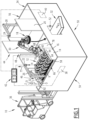
- the installation 10 is adapted to unstack a set of tires 12 initially stacked on a first rack 14 (in the foreground) forming a support 16 for the set of tires 12.
- the installation 10 is also adapted to unstack tires 18 (of which only one is shown) on a second rack 20 (in the background).
- the installation 10 comprises two sensors 22, 24 advantageously located above the first rack 14 and the second rack 20, and two structures 26, 28, for example in the form of brackets, respectively supporting the two sensors.
- the installation 10 comprises a robot 30 adapted to move tires from the first rack 14 or the second rack 20 to a receptacle 32, for example a conveyor belt adapted to carry the tires.
- the installation 10 is configured to process a single rack, or more than two racks, with a single sensor or more than two sensors.
- the installation 10 advantageously comprises a protective enclosure 34 surrounding the first rack 14, the second rack 20 and the robot 30.
- the installation 10 comprises a handling machine 36 for successively moving the first rack 14 and the second rack 20 between an active position (shown in the figure 1 ), in which the first rack and the second rack are respectively under the two sensors 22, 24, and an inactive position (not shown), in which the first rack 14 and the second rack 20 are outside the enclosure 34, for example to be loaded with tires.
- the installation 10 advantageously comprises two lifting systems 38, 40, schematically represented in the figure 1 , adapted to adjust the height of the first rack 14 and the second rack 20, as will be explained below.
- the installation 10 also includes a control and processing system 42 (shown schematically in the figure 1 ) to control the two sensors 22, 24, the robot 30, the lifting systems 38, 40, and to implement certain steps of a method according to the invention.
- a control and processing system 42 shown schematically in the figure 1 to control the two sensors 22, 24, the robot 30, the lifting systems 38, 40, and to implement certain steps of a method according to the invention.
- the installation 10 is not a static installation to which the set of tires 12 is brought, but a mobile installation, for example adapted to unload tires from a trailer of a truck, or more generally from a container (not shown).
- the robot 30 and the sensor(s) 22, 24 are integral with one or more support(s) movable relative to the set of tires. According to a particular embodiment, these supports are moved as the trailer is unloaded.
- the enclosure 34 is for example rectangular or square in shape.
- the enclosure 34 comprises for example a first face 44 defining two inputs 46, 48 allowing the first rack 14 and the second rack 20 to be placed in their active positions.
- the enclosure 34 comprises for example a second face 50, advantageously opposite the first face 44, and defining an output 52 crossed by the conveyor belt.
- the sensor supports 26, 28 are for example fixed to the ground.
- the support 16 of the tires 12 comprises for example a base 58, and two faces 60, 62 opposite in a storage direction X of the tires for example substantially horizontal.
- the support 16 allows easy access to the tires 12 from above and in a transverse direction Y substantially perpendicular to the storage direction X and for example substantially horizontal.
- the tires 12 are stacked on the support in a superposition direction Z substantially perpendicular to the storage direction X and the transverse direction Y, for example substantially vertical.
- the superposition direction Z is not substantially vertical, in particular if the set of tires 12 is cantilevered, or resting against any support (not shown).
- the tire assembly 12 comprises rows of tires 64 superimposed in the superposition direction Z and extending in the storage direction X, the tires of each of the rows being arranged sidewall to sidewall obliquely relative to the superposition direction Z and relative to the storage direction X.
- the set of tires 12 comprises two groups 66, 68 of superimposed rows 64.
- the groups 66, 68 are juxtaposed in the transverse direction Y.
- the tires 12 of any one of the rows 64 are inclined in one direction relative to the superposition direction Z, and the tires of the adjacent row(s) 64 in the superposition direction Z are advantageously inclined in the opposite direction.
- upper portions 70 ( figure 5 ) tires 12 taken from one of the rows 64 not located at the top of the stack are received in central housings 72 of the tires 12 of the row 64 located immediately above this row.
- Such a stacking mode is called “chain”, and gives great compactness to the stack.
- the tires 12 of the adjacent row(s) in the superposition direction Z are inclined in the same direction, or in any case not systematically in the opposite direction.
- this type of stacking means that, in an upper row 74 (not covered by other tires), only one of the tires 12 is a free tire 76, that is to say not covered, even partially, by another of the tires 12.
- the upper row 74 is one of them, for example the one located highest in the superposition direction Z.
- the free tire 76 is adapted to be lifted by the robot 30 in the Z superposition direction relative to the support 16 without moving or dropping the other tires of the tire set 12.
- the lifting systems 38, 40 are adapted to adjust the distance H between the one of the sensors 22, 24 located above and the set of tires 12 in a thresholding direction Z1 which is for example the superposition direction Z.
- the two sensors 22, 24 are advantageously identical, so only sensor 22 will be described below.
- the sensor 22 is adapted to be directed towards the tire assembly 12.
- the sensor 22 is a matrix time-of-flight (TOF) camera, for example with a resolution of 640 x 480 pixels, with an integrated light source (not shown).
- TOF time-of-flight
- the sensor 22 is adapted to measure in real time a three-dimensional (3D) scene and provide a three-dimensional image 77 representative of an exterior surface S ( figure 5 ) of at least part of the set of tires 12 in a local reference frame (O, X, Y, Z) linked to the support 16.
- the sensor 22 is adapted to illuminate the set of tires 12 with at least one flash of light, and to measure the time that this flash takes to complete the journey between the tires 12 and the sensor 22.
- the time of flight of this flash is directly proportional to the distance between the camera and the outer surface S of the tires 12. This time of flight measurement is carried out independently for each pixel of the camera, which makes it possible to obtain a 3D image of the measured object.
- the measurement principle is therefore very similar to that of laser scanners, with however the advantage of allowing the acquisition of a surface in space, and not of a single line.
- the senor 22 is capable of providing a plurality of three-dimensional images, and of providing an average thereof, in order to reduce the measurement noise.
- the averaging is performed by the control and processing system 42.
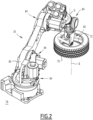
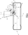
- the robot 30 comprises a base 78, an articulated arm 80 fixed on the base, and a gripper 82 located at the free end of the articulated arm.
- the robot 30 advantageously comprises several articulated arms.
- the base 78 is for example located between the first rack 14 and the second rack 20 in the transverse direction Y.
- the articulated arm 80 comprises several joints 84 allowing the robot 30 to reach any of the tires of the tire set 12 when the first rack 14 is in its active position, and to perform relative movements to move this tire and place it on the conveyor belt.
- the gripper 82 comprises for example a body 86 mounted on the articulated arm 80, at least two jaws 88, 90 mounted on the body, and an actuator 92.
- the body 86 is for example rotatably mounted on the articulated arm 80 around an axis of rotation D.
- the two jaws 88, 90 are movable relative to each other between an open position ( figures 2 , 3 And 4 ), in which the two jaws are apart from each other, and a closed position ( figure 4 ), in which the two jaws are adapted to pinch a sidewall 94 of the free tire 76.
- one of the two jaws 88, 90 is fixed relative to the body 86 and projects from the body along a first axis D1 forming an angle ⁇ with the axis of rotation D, the angle ⁇ being advantageously between 70° and 110°.
- the other of the two jaws 88, 90 is rotatably mounted on the body 86 around a second axis D2 substantially orthogonal to the axis of rotation D.
- Each of the two jaws 88, 90 advantageously comprises an end piece 95, 96 forming an angular portion of a torus.
- the actuator 92 is adapted to act on the other of the two jaws 88, 90.
- the two jaws 88, 90 are movable relative to the body 86.
- the control and processing system 42 ( figure 1 ) comprises at least one central unit 98 and a memory 100.
- the control and processing system 42 is connected to the two sensors 22, 24, to the two lifting systems 38, 40 and to the robot 30.
- the central unit 98 is adapted to read software instructions in the memory 100, to identify the free tire 76 and to provide position data representative of the position of the free tire 76 in the local reference frame (O, X, Y, Z).
- the position data comprise, for example, three coordinates X0, Y0, Z0 of a center ⁇ of the free tire 76 in the local reference frame (O, X, Y, Z), and two angles ⁇ 1, ⁇ 2 representative of an orientation of the free tire 76, for example relative to the storage direction X and to the transverse direction Y.
- the position data include a Boolean parameter representative of the manner (among two possibilities) in which the sidewalls 94, 102 are located relative to the superposition direction Z.
- the Boolean parameter is for example representative of the face of the free tire 76 directed upwards.
- Handling equipment 10 for example brought the second rack 20 into the active position in the enclosure 34. While the installation 10 unstacks tires 18 present on the second rack 20 (only one of which is shown in the figure 1 ), the handling machine 36 removes an empty rack where the first rack 14 is shown on the figure 1 , and brings the first rack 14 loaded with the set of tires 12. Then, the installation 10 unstacks the tires 12 present on the first rack 14. These steps alternate, so that the operations of handling the racks and the steps which unstack the tires are carried out in masked time. In other words, as soon as the robot 30 has finished emptying a rack, it can move on to another rack without downtime linked to the handling of the racks.
- the central unit 98 reads, or has read, the software instructions in the memory 100, which leads the installation 10 to implement a method according to the invention.
- a step a) of the method at least one three-dimensional image 77 is obtained using the sensor 22 directed towards the set of tires 12. Then the system of command and processing 42 performs a step b) determination of an area of interest 104 ( figure 5 ) in the three-dimensional image 77, a step c) of identifying, in the area of interest, at least one free tire 76 among the set of tires 12, and of obtaining position data of the free tire 76 in the local reference frame (O, X, Y, Z), and a step d) of controlling the robot 30 using the position data. In a step e) the free tire 76 is moved by the robot 30 away from the other tires of the set of tires 12.
- step a) the control and processing system 42 drives the sensor 22 and receives data forming the three-dimensional image 77.
- the control and processing system 42 drives the sensor 22 and receives data forming the three-dimensional image 77.
- eight three-dimensional images are taken by the sensor 22.
- the total acquisition time is for example approximately 500 milliseconds.
- the area of interest 104 is for example determined from the known shape and active position of the first rack 14, by retaining only the data relating to points of the surface S located in a housing 106 defined by the first rack 14.
- the area of interest 104 is for example determined from the known shape and active position of the first rack 14, by retaining only the data relating to points of the surface S located in a housing 106 defined by the first rack 14.
- only points located in a parallelepiped having x coordinates located in a certain interval along the storage direction X, y coordinates located in a certain interval along the transverse direction Y, and z coordinates located in a certain interval along the superposition direction Z are retained.
- Step b) makes it possible to make the search for the highest 12 tires more reliable.
- a thresholding of the area of interest 104 is carried out in a thresholding direction Z1 to obtain a slice 108 ( figure 5 ) of the area of interest (104), the slice comprising the upper row 74 among the rows of tires 64 in the superposition direction Z. Then, according to the invention, an analysis of the slice 108 is carried out to identify the free tire 76.
- an adjustment of the distance between the support 16 and the sensor 22 is carried out so that the slice 108 extends over distances from the sensor of between 1.5 m and 2.5 m, preferably between 1.8 m and 2.2 m, in the thresholding direction Z1.
- this conditions the quality of the three-dimensional images 77, therefore the number of three-dimensional images which are taken, and therefore the duration of steps a) to c).
- step a) is repeated after the adjustment.
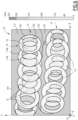
- the analysis of the slice 108 comprises obtaining a two-dimensional image of the slice, analogous to the two-dimensional image 110 represented in the figure 6 .
- the two-dimensional image 110 has a plurality of pixels 112, each pixel having a value representative of a distance in an analysis direction Z2 between the sensor 22 and tires of the upper row 74.
- the analysis direction Z2 is the superposition direction Z
- the two-dimensional image 110 comprises two upper rows 74.
- the tires 12 have inclinations in opposite directions relative to the superposition direction Z, unlike the tires 12 shown in the figure 1 .
- the two-dimensional image 110 shown in the figure 6 has been simplified to remain readable. It comprises six types of zones 114A, 114B, 114C, 114D, 114E, 114F corresponding to six ranges of distances between the sensor 22 and the surface S according to the analysis direction Z2. The closer the points filling the zones are, the further the surface S is from the sensor 22.
- the pixels 112 of the two-dimensional images 110 have, for example, gray levels corresponding to more than six zones.
- the analysis of the slice 108 comprises for example a particle analysis (in English " blob analysis ") of the two-dimensional image 110 to obtain a processed image 116 ( figure 7 ) comprising disjoint particles 118 having shapes corresponding to the upper parts 70 of the tires 12 present in the upper rows 74.
- the analysis of the slice 108 finally comprises the selection of one of the particles 118, the selected particle 120 having a shape corresponding to the upper part 70 of the free tire 76.
- Particle analysis associates pixels of the two-dimensional image 110 by neighborhood and allows to obtain labeled objects, the particles 118, as output.
- the analysis of the slice 108 advantageously comprises obtaining position parameters representative of respective positions of the particles 118 in the processed image 116 and orientation parameters representative of respective orientations of the particles in the processed image, the selection of one of the particles using at least some of the position parameters and some of the orientation parameters.
- orientation parameters are obtained by an analysis of the convexity or concavity of an edge 122 of the particles 118.
- Each of the particles 118 is advantageously associated with an “identity card” comprising for example the surface, the position in the two axes X, Y of the two-dimensional image, and shape characteristics (concave, convex, etc.).
- obtaining position data representative of the position of the free tire 76 comprises for example an iterative generation, from at least a part of the three-dimensional image 77, of successive two-dimensional images 124 (one of which is shown in the figure 8 ) of the free tire 76 according to viewing directions Z3 resulting from successive rotations in the local reference frame (O, X, Y, Z), and an identification of the free tire 76 as having a substantially circular shape in one of the two-dimensional images 124, and the selection of the viewing direction Z3 of this two-dimensional image. Then, from the selected viewing direction Z3, the two parameters ⁇ 1, ⁇ 2 representative of the orientation of the free tire 76 in the local reference frame (O, X, Y, Z) are obtained.
- the viewing direction Z3 is the analysis direction Z2, i.e. the superposition direction Z in the example.
- the free tire 76 has an elliptical shape on the two-dimensional image 124.
- the iterative generation varies the viewing direction Z3 until the viewing direction is substantially parallel to the axis ⁇ of the free tire 76, so that, in the corresponding two-dimensional image 124, the free tire 76 has a substantially circular shape.
- the central housing 72 of the free tire 76 appears to be substantially circular.
- the position data of the free tire 76 are easily calculated, for example, the coordinates X0, Y0, Z0 of the center ⁇ of the free tire and two angles ⁇ 1, ⁇ 2 relative to the local reference frame (O, X, Y, Z).
- the sidewall 94 of the tire is used to determine the free tire position, since the sidewall provides an optically stable surface.
- step d) the control and processing system 42 controls the robot 30 based on the position data of the free tire 76.
- the software instructions for processing 3D data (three-dimensional images 77) and data exchange with the robot 30 are, for example, developed using the National Instruments “LabVIEW” software development platform.
- the "Vision development module” (VDM) image processing library advantageously allows the thresholding and particle analysis sub-steps to be carried out.
- step e) the robot 30 grasps the free tire 76 using the gripper 82.
- the gripper 82 according to the invention is particularly well suited for quickly and efficiently grasping a tire.
- steps a) to c) are also performed at least partly in masked time.
- the robot 30 moves a tire in 5 to 6 seconds, which leaves a time window to perform the measurements by the sensor 22 and the calculations to determine the next free tire.
- steps a) to e) for unstacking the set of tires 12 are fully automated.
- the method is faster and/or less expensive than the methods currently used.
- the process advantageously allows a truck containing 1000 tires to be unloaded in less than an hour, or one tire every 3 seconds or so. For example, it is possible to install a two-arm robot working alternately, each arm completing a cycle in 6 seconds, for tire unstacking every 3 seconds.
Landscapes
- Engineering & Computer Science (AREA)
- Robotics (AREA)
- Mechanical Engineering (AREA)
- Physics & Mathematics (AREA)
- General Physics & Mathematics (AREA)
- Image Analysis (AREA)
- Length Measuring Devices By Optical Means (AREA)
- Image Processing (AREA)
Claims (9)
- Verfahren zum Entstapeln einer Anordnung von Reifen (12), die auf einem Träger (16) in einer Überlagerungsrichtung (Z) gestapelt sind, die Anordnung von Reifen (12) umfassend Reihen von Reifen (64) umfasst, die in der Überlagerungsrichtung (Z) übereinander liegen und sich in einer Ordnungsrichtung (X) im Wesentlichen senkrecht zu der Überlagerungsrichtung (Z) erstrecken, wobei die Reifen (12) jeder der Reihen von Reifen (64) Flanke an Flanke schräg zu der Überlagerungsrichtung (Z) angeordnet sind, wobei jeder der Reifen (12) einen oberen Abschnitt (70) aufweist und eine mittlere Aufnahme (72) definiert, das Verfahren umfassend die folgenden Schritte:a) Erlangen mindestens eines dreidimensionalen Bilds (77) mittels mindestens eines dreidimensionalen Laufzeitsensors (22), der auf die Anordnung von Reifen (12) gerichtet ist, wobei das dreidimensionale Bild (77) repräsentativ für eine Außenfläche (S) mindestens eines Teils der Anordnung von Reifen (12) in einem lokalen Koordinatensystem (O, X, Y, Z) ist, das mit dem Träger (16) verbunden ist;b) Bestimmen eines Bereichs von Interesse (104) in dem dreidimensionalen Bild (77);c) Identifizieren mindestens eines freien Reifens (76) aus dem Anordnung von Reifen (12) in dem Bereich von Interesse (104), wobei der freie Reifen (76) geeignet ist, um in der Überlagerungsrichtung (Z) in Bezug auf den Träger (16) angehoben zu werden, ohne die anderen der Reifen der Anordnung von Reifen (12) zu bewegen, und Erlangen von Positionsdaten (X0, Y0, Z0, α1, α2), die repräsentativ für die Position des freien Reifens (76) in dem lokalen Koordinatensystem (O, X, Y, Z) sind;d) Steuern eines Roboters (30) unter Verwendung der Positionsdaten (X0, Y0, Z0, α1, α2); unde) Bewegen des freien Reifens (76) durch den Roboter (30) weg von den anderen Reifen der Anordnung von Reifen (12),dadurch gekennzeichnet, dass der Identifizierungsschritt Folgendes umfasst:- Schwellenwertbildung des Bereichs von Interesse (104) in einer Schwellenwertrichtung (Z1), um einen Teilabschnitt (108) des Bereichs von Interesse (104) zu erlangen, der Teilabschnitt (108) umfassend eine obere Reihe (74) unter den Reihen von Reifen (64) entlang der Überlagerungsrichtung (Z), und - Analyse des Teilabschnitts (108), um den freien Reifen (76) zu identifizieren, die Analyse des Teilabschnitts (108) umfassend:- Erlangung, anhand des Teilabschnitts (108), eines zweidimensionalen Bilds (110), das eine Vielzahl von Pixeln (112) aufweist, wobei jedes Pixel der Vielzahl einen Wert aufweist, der repräsentativ für einen Abstand in einer Analyserichtung (Z2) zwischen dem Sensor (22) und Reifen (12) der oberen Reihe (74) ist,- Partikelanalyse des zweidimensionalen Bilds (110), um ein verarbeitetes Bild (116) mit disjunkten Partikeln (118) zu erlangen, die Formen aufweisen, die den oberen Teilen der Reifen entsprechen, die in der oberen Reihe (74) vorhanden sind, und- Auswahl eines der Partikel (118), wobei das ausgewählte Partikel (120) eine Form aufweist,die dem oberen Teil (70) des freien Reifens (76) entspricht.
- Verfahren nach Anspruch 1, wobei ein Abstand zwischen dem Träger (16) und dem Sensor (22) eingestellt wird, sodass sich der Teilabschnitt (108) beim Erlangen des dreidimensionalen Bilds (77) über Abstände vom Sensor (22) zwischen 1,5 m und 2,5 m, vorzugsweise zwischen 1,8 m und 2,2 m, in der Schwellenwertrichtung (Z1) erstreckt.
- Verfahren nach Anspruch 1 oder 2, wobei die Analyse des Teilabschnitts (108) ferner ein Erlangen von Positionsparametern, die repräsentativ für jeweilige Positionen der Partikel (118) in dem verarbeiteten Bild (116) sind, und von Ausrichtungsparametern, die repräsentativ für jeweilige Ausrichtungen der Partikel (118) in dem verarbeiteten Bild (116) sind, umfasst, wobei die Auswahl eines der Partikel (118) zumindest einige der Positionsparameter und einige der Ausrichtungsparameter verwendet.
- Verfahren nach Anspruch 3, wobei mindestens einige der Ausrichtungsparameter durch eine Analyse der Konvexität oder Konkavität eines Rands (122) der Partikel (118) erlangt werden.
- Verfahren nach einem der Ansprüche 1 bis 4, wobei das Erlangen von Positionsdaten (X0, Y0, Z0, α1, α2), die repräsentativ für die Position des freien Reifens (76) sind, Folgendes umfasst:- iterative Erzeugung, anhand mindestens eines Teils des dreidimensionalen Bilds (77), von aufeinanderfolgenden zweidimensionalen Bildern (124) des freien Reifens (76) gemäß Blickrichtungen (Z3), die aus aufeinanderfolgenden Drehungen in dem lokalen Koordinatensystem (O, X, Y, Z) resultieren;- Identifizieren des freien Reifens (76) als im Wesentlichen kreisförmig in einem der zweidimensionalen Bilder (124) und Auswählen der Blickrichtung (Z3) dieses zweidimensionalen Bilds (124); und- Erlangen, anhand der ausgewählten Blickrichtung, von mindestens zwei Parametern (α1, α2), die repräsentativ für eine Ausrichtung des freien Reifens (76) in dem lokalen Koordinatensystem (O, X, Y, Z) sind.
- Verfahren nach einem der Ansprüche 1 bis 5, wobei der Roboter (30) einen Gelenkarm (80) und einen Greifer (82) umfasst, der angepasst ist, um den freien Reifen (76) zu greifen, der Greifer (82) umfassend:- einen Körper (86), der an dem Gelenkarm (80) montiert ist; und- mindestens zwei Backen (88, 90), die an dem Körper (86) montiert sind, wobei die Backen (88, 90) in Bezug aufeinander zwischen einer offenen Position, in der die beiden Backen (88, 90) voneinander beabstandet sind, und einer geschlossenen Position, in der die zwei Backen (88, 90) angepasst sind, um eine Seitenwand (94) des losen Reifens (76) einzuklemmen, bewegbar sind.
- Verfahren nach Anspruch 6, wobei jede der zwei Backen (88, 90) ein Endstück (95, 96) umfasst, das einen torusförmigen Winkelabschnitt bildet.
- Verfahren nach Anspruch 6 oder 7, wobei:- der Körper (86) drehbar um eine Drehachse (D) an dem Gelenkarm (80) montiert ist;- eine der zwei Backen (88, 90) in Bezug auf den Körper (86) feststehend ist und von dem Körper (86) entlang einer ersten Achse (D1) hervorsteht, die mit der Drehachse (D) einen Winkel (α) bildet, wobei der Winkel (α) zwischen 70° und 110° ist; und- die andere der zwei Backen (88, 90) drehbar um eine zweite Achse (D2), die im Wesentlichen orthogonal zu der Drehachse (D) ist, an dem Körper (86) montiert ist.
- Anlage (10) zum Entstapeln einer Anordnung von Reifen (12), die auf einem Träger (16) in einer Überlagerungsrichtung (Z) gestapelt sind, die Anordnung von Reifen (12) umfassend Reihen von Reifen (64) umfasst, die in der Überlagerungsrichtung (Z) übereinander liegen und sich in einer Ordnungsrichtung (X) im Wesentlichen senkrecht zu der Überlagerungsrichtung (Z) erstrecken, wobei die Reifen (12) jeder der Reihen von Reifen (64) Flanke an Flanke schräg zu der Überlagerungsrichtung (Z) angeordnet sind, wobei jeder der Reifen (12) einen oberen Abschnitt (70) aufweist und eine mittlere Aufnahme (72) definiert, die Anlage 10 umfassend:- mindestens einen dreidimensionalen Laufzeitsensor (22), der auf die Anordnung von Reifen (12) gerichtet und konfiguriert ist, um mindestens ein dreidimensionales Bild (77) bereitzustellen, das repräsentativ für eine Außenfläche (S) mindestens eines Teils der Anordnung von Reifen (12) in einem lokalen Koordinatensystem (O, X, Y, Z) ist, das mit dem Träger (16) verbunden ist;- ein Steuer- und Verarbeitungssystem (42), das zu Folgendem konfiguriert ist:- Bestimmen eines Bereichs von Interesse (104) in dem dreidimensionalen Bild (77), und- Identifizieren mindestens eines freien Reifens (76) aus dem Anordnung von Reifen (12) in dem Bereich von Interesse (104), wobei der freie Reifen (76) geeignet ist, um in der Überlagerungsrichtung (Z) in Bezug auf den Träger (16) angehoben zu werden, ohne die anderen der Reifen der Anordnung von Reifen (12) zu bewegen, und Erlangen von Positionsdaten (X0, Y0, Z0, α1, α2), die repräsentativ für die Position des freien Reifens (76) in dem lokalen Koordinatensystem (O, X, Y, Z) sind; und- einen Roboter (30), der angepasst ist, um den freien Reifen (76) von den anderen Reifen der Anordnung von Reifen (12) wegzubewegen, wobei das Steuer- und Verarbeitungssystem (42) angepasst ist, um den Roboter (30) unter Verwendung der Positionsdaten (X0, Y0, Z0, α1, α2) zu steuern,dadurch gekennzeichnet, dass der Identifizierungsschritt Folgendes umfasst:- Schwellenwertbildung des Bereichs von Interesse (104) in einer Schwellenwertrichtung (Z1), um einen Teilabschnitt (108) des Bereichs von Interesse (104) zu erlangen, der Teilabschnitt (108) umfassend eine obere Reihe (74) unter den Reihen von Reifen (64) entlang der Überlagerungsrichtung (Z), und - Analyse des Teilabschnitts (108), um den freien Reifen (76) zu identifizieren,die Analyse des Teilabschnitts (108) umfassend:- Erlangung, anhand des Teilabschnitts (108), eines zweidimensionalen Bilds (110), das eine Vielzahl von Pixeln (112) aufweist, wobei jedes Pixel der Vielzahl einen Wert aufweist, der repräsentativ für einen Abstand in einer Analyserichtung (Z2) zwischen dem Sensor (22) und Reifen (12) der oberen Reihe (74) ist,- Partikelanalyse des zweidimensionalen Bilds (110), um ein verarbeitetes Bild (116) mit disjunkten Partikeln (118) zu erlangen, die Formen aufweisen, die den oberen Teilen der Reifen entsprechen, die in der oberen Reihe (74) vorhanden sind, und- Auswahl eines der Partikel (118), wobei das ausgewählte Partikel (120) eine Form aufweist,die dem oberen Teil (70) des freien Reifens (76) entspricht.
Applications Claiming Priority (1)
| Application Number | Priority Date | Filing Date | Title |
|---|---|---|---|
| FR2013482A FR3118014B1 (fr) | 2020-12-17 | 2020-12-17 | Procédé pour désempiler des pneus empilés en rangées inclinées |
Publications (3)
| Publication Number | Publication Date |
|---|---|
| EP4015422A2 EP4015422A2 (de) | 2022-06-22 |
| EP4015422A3 EP4015422A3 (de) | 2022-08-31 |
| EP4015422B1 true EP4015422B1 (de) | 2025-02-19 |
Family
ID=75108480
Family Applications (1)
| Application Number | Title | Priority Date | Filing Date |
|---|---|---|---|
| EP21215002.3A Active EP4015422B1 (de) | 2020-12-17 | 2021-12-16 | Verfahren zum entstapeln von reifen, die in geneigten reihen gestapelt sind |
Country Status (3)
| Country | Link |
|---|---|
| EP (1) | EP4015422B1 (de) |
| ES (1) | ES3025966T3 (de) |
| FR (1) | FR3118014B1 (de) |
Families Citing this family (3)
| Publication number | Priority date | Publication date | Assignee | Title |
|---|---|---|---|---|
| FR3148538B1 (fr) * | 2023-05-11 | 2025-04-11 | Michelin & Cie | Chaînage de pneumatiques par moyens robotiques employant la vision tridimensionnelle |
| CN116513803B (zh) * | 2023-07-03 | 2023-08-25 | 安徽哈工道一智能制造技术有限公司 | 一种汽车加工用码垛机器人的搬运装置 |
| CN118083557A (zh) * | 2024-01-29 | 2024-05-28 | 青岛众屹科锐工程技术有限公司 | 一种自适应胎圈抓取机械手 |
Family Cites Families (4)
| Publication number | Priority date | Publication date | Assignee | Title |
|---|---|---|---|---|
| DE102007026956A1 (de) * | 2007-06-12 | 2008-12-18 | Kuka Innotec Gmbh | Verfahren und System zum Roboter geführten Depalettieren von Reifen |
| MX358984B (es) * | 2013-01-15 | 2018-09-11 | Wynright Corp | Cargador/descargador automático de neumáticos para apilar/desapilar neumáticos en un trailer. |
| US9507995B2 (en) * | 2014-08-29 | 2016-11-29 | X Development Llc | Combination of stereo and structured-light processing |
| DE202020100320U1 (de) * | 2020-01-22 | 2020-03-18 | Ssi Schäfer Automation Gmbh (At) | Vorrichtung zur abschattungsfreien Vermessung und/oder Abbildung des Inneren eines nach oben offenen Behälters mittels eines Sensors |
-
2020
- 2020-12-17 FR FR2013482A patent/FR3118014B1/fr active Active
-
2021
- 2021-12-16 ES ES21215002T patent/ES3025966T3/es active Active
- 2021-12-16 EP EP21215002.3A patent/EP4015422B1/de active Active
Also Published As
| Publication number | Publication date |
|---|---|
| FR3118014B1 (fr) | 2023-05-05 |
| ES3025966T3 (en) | 2025-06-10 |
| EP4015422A2 (de) | 2022-06-22 |
| EP4015422A3 (de) | 2022-08-31 |
| FR3118014A1 (fr) | 2022-06-24 |
Similar Documents
| Publication | Publication Date | Title |
|---|---|---|
| EP4015422B1 (de) | Verfahren zum entstapeln von reifen, die in geneigten reihen gestapelt sind | |
| EP3448589B1 (de) | Verfahren und vorrichtung zum orientieren von einem obst mit einem umbilicus insbesondere zu seinem verpacken | |
| EP3256267B1 (de) | Einrichtung zum separieren und vereinzeln von heterogenem postgut mit einem laser-basierten sichtsystem | |
| CA2659544C (fr) | Procede et installation de mise en lots de produits de boulangerie industrielle | |
| EP3850397B1 (de) | Verfahren zur strassenerkennung für ein mit einem lidarsensor ausgestattetes kraftfahrzeug | |
| FR3081248A1 (fr) | Systeme et procede de determination d’un emplacement pour le placement d'un paquet | |
| FR2786268A1 (fr) | Installation et procede optiques de determination des positions relatives d'au moins deux objets dans l'espace | |
| EP0076182B1 (de) | Verfahren, Gerät und Verwendung mit Wahlmöglichkeit zwischen einer Menge von Paketen und deren Transport | |
| WO2017103489A1 (fr) | Système et procédé pour la correction d'une trajectoire d'un effecteur porté par un robot | |
| WO2003065287A1 (fr) | Procede et dispositif d'identification de caracteres inscrits sur une plaque de semi-conducteur comportantau moins une marque d'orientation | |
| EP3080664B1 (de) | Device and method for imaging an object | |
| EP0385528B1 (de) | Verfahren und System zur Bestimmung der Position und der relativen Lage zweier Objekte im Raum | |
| FR2939190A1 (fr) | Dispositif et procede pour mesurer une caracteristique geometrique relative a la cambrure d'une lentille ophtalmique | |
| FR3102468A1 (fr) | Systeme et procede de paletisation et depalettisation | |
| WO2016091749A1 (fr) | Procédé d'obtention d'une image d'un échantillon, et système associé d'imagerie sans lentille | |
| EP2812161B1 (de) | Einheit und verfahren zum automatischen festhaken von teilen auf komplexen trägern | |
| EP0781396A1 (de) | Verfahren zur korrelation von-durch bilderfassungssystemen ausgefuhrten- dreidimensionalen messungen und anordnung zur durchfuhrung dieses verfahrens | |
| EP1391686A1 (de) | Verfahren und Vorrichtung zur Lokalisierung von Objekten mittels einer optischen Messtechnik | |
| WO2018100267A1 (fr) | Système et procède de positionnement et d'inspection optique d'un objet | |
| EP2257764B1 (de) | Verfahren und vorrichtung zur messung und positionierung von objekten | |
| FR2662329A1 (fr) | Appareil pour la cueillette des fruits et procede de recherche d'objets cibles. | |
| FR2786267A1 (fr) | Procede et dispositif de determination de la position de l'axe optique d'une camera par rapport a un repere visible | |
| EP4368018A1 (de) | Feldsprizte zum punktgenauen spritzen | |
| EP0388339A2 (de) | Schaltung zur Erkennung der Lage eines Objekts | |
| FR2884781A1 (fr) | Methode et dispositif de calibrage de camera |
Legal Events
| Date | Code | Title | Description |
|---|---|---|---|
| PUAI | Public reference made under article 153(3) epc to a published international application that has entered the european phase |
Free format text: ORIGINAL CODE: 0009012 |
|
| STAA | Information on the status of an ep patent application or granted ep patent |
Free format text: STATUS: THE APPLICATION HAS BEEN PUBLISHED |
|
| AK | Designated contracting states |
Kind code of ref document: A2 Designated state(s): AL AT BE BG CH CY CZ DE DK EE ES FI FR GB GR HR HU IE IS IT LI LT LU LV MC MK MT NL NO PL PT RO RS SE SI SK SM TR |
|
| PUAL | Search report despatched |
Free format text: ORIGINAL CODE: 0009013 |
|
| AK | Designated contracting states |
Kind code of ref document: A3 Designated state(s): AL AT BE BG CH CY CZ DE DK EE ES FI FR GB GR HR HU IE IS IT LI LT LU LV MC MK MT NL NO PL PT RO RS SE SI SK SM TR |
|
| RIC1 | Information provided on ipc code assigned before grant |
Ipc: G01B 11/24 20060101ALI20220728BHEP Ipc: B25J 9/16 20060101ALI20220728BHEP Ipc: B65G 61/00 20060101AFI20220728BHEP |
|
| STAA | Information on the status of an ep patent application or granted ep patent |
Free format text: STATUS: REQUEST FOR EXAMINATION WAS MADE |
|
| 17P | Request for examination filed |
Effective date: 20230201 |
|
| RBV | Designated contracting states (corrected) |
Designated state(s): AL AT BE BG CH CY CZ DE DK EE ES FI FR GB GR HR HU IE IS IT LI LT LU LV MC MK MT NL NO PL PT RO RS SE SI SK SM TR |
|
| GRAP | Despatch of communication of intention to grant a patent |
Free format text: ORIGINAL CODE: EPIDOSNIGR1 |
|
| STAA | Information on the status of an ep patent application or granted ep patent |
Free format text: STATUS: GRANT OF PATENT IS INTENDED |
|
| INTG | Intention to grant announced |
Effective date: 20241120 |
|
| GRAS | Grant fee paid |
Free format text: ORIGINAL CODE: EPIDOSNIGR3 |
|
| GRAA | (expected) grant |
Free format text: ORIGINAL CODE: 0009210 |
|
| STAA | Information on the status of an ep patent application or granted ep patent |
Free format text: STATUS: THE PATENT HAS BEEN GRANTED |
|
| AK | Designated contracting states |
Kind code of ref document: B1 Designated state(s): AL AT BE BG CH CY CZ DE DK EE ES FI FR GB GR HR HU IE IS IT LI LT LU LV MC MK MT NL NO PL PT RO RS SE SI SK SM TR |
|
| REG | Reference to a national code |
Ref country code: GB Ref legal event code: FG4D Free format text: NOT ENGLISH |
|
| REG | Reference to a national code |
Ref country code: CH Ref legal event code: EP |
|
| REG | Reference to a national code |
Ref country code: DE Ref legal event code: R096 Ref document number: 602021026324 Country of ref document: DE |
|
| REG | Reference to a national code |
Ref country code: IE Ref legal event code: FG4D Free format text: LANGUAGE OF EP DOCUMENT: FRENCH |
|
| REG | Reference to a national code |
Ref country code: ES Ref legal event code: FG2A Ref document number: 3025966 Country of ref document: ES Kind code of ref document: T3 Effective date: 20250610 |
|
| REG | Reference to a national code |
Ref country code: NL Ref legal event code: MP Effective date: 20250219 |
|
| PG25 | Lapsed in a contracting state [announced via postgrant information from national office to epo] |
Ref country code: RS Free format text: LAPSE BECAUSE OF FAILURE TO SUBMIT A TRANSLATION OF THE DESCRIPTION OR TO PAY THE FEE WITHIN THE PRESCRIBED TIME-LIMIT Effective date: 20250519 |
|
| PG25 | Lapsed in a contracting state [announced via postgrant information from national office to epo] |
Ref country code: FI Free format text: LAPSE BECAUSE OF FAILURE TO SUBMIT A TRANSLATION OF THE DESCRIPTION OR TO PAY THE FEE WITHIN THE PRESCRIBED TIME-LIMIT Effective date: 20250219 |
|
| PG25 | Lapsed in a contracting state [announced via postgrant information from national office to epo] |
Ref country code: PL Free format text: LAPSE BECAUSE OF FAILURE TO SUBMIT A TRANSLATION OF THE DESCRIPTION OR TO PAY THE FEE WITHIN THE PRESCRIBED TIME-LIMIT Effective date: 20250219 |
|
| REG | Reference to a national code |
Ref country code: LT Ref legal event code: MG9D |
|
| PG25 | Lapsed in a contracting state [announced via postgrant information from national office to epo] |
Ref country code: NO Free format text: LAPSE BECAUSE OF FAILURE TO SUBMIT A TRANSLATION OF THE DESCRIPTION OR TO PAY THE FEE WITHIN THE PRESCRIBED TIME-LIMIT Effective date: 20250519 Ref country code: IS Free format text: LAPSE BECAUSE OF FAILURE TO SUBMIT A TRANSLATION OF THE DESCRIPTION OR TO PAY THE FEE WITHIN THE PRESCRIBED TIME-LIMIT Effective date: 20250619 |
|
| PG25 | Lapsed in a contracting state [announced via postgrant information from national office to epo] |
Ref country code: NL Free format text: LAPSE BECAUSE OF FAILURE TO SUBMIT A TRANSLATION OF THE DESCRIPTION OR TO PAY THE FEE WITHIN THE PRESCRIBED TIME-LIMIT Effective date: 20250219 |
|
| PG25 | Lapsed in a contracting state [announced via postgrant information from national office to epo] |
Ref country code: HR Free format text: LAPSE BECAUSE OF FAILURE TO SUBMIT A TRANSLATION OF THE DESCRIPTION OR TO PAY THE FEE WITHIN THE PRESCRIBED TIME-LIMIT Effective date: 20250219 |
|
| PG25 | Lapsed in a contracting state [announced via postgrant information from national office to epo] |
Ref country code: LV Free format text: LAPSE BECAUSE OF FAILURE TO SUBMIT A TRANSLATION OF THE DESCRIPTION OR TO PAY THE FEE WITHIN THE PRESCRIBED TIME-LIMIT Effective date: 20250219 Ref country code: PT Free format text: LAPSE BECAUSE OF FAILURE TO SUBMIT A TRANSLATION OF THE DESCRIPTION OR TO PAY THE FEE WITHIN THE PRESCRIBED TIME-LIMIT Effective date: 20250620 |
|
| PG25 | Lapsed in a contracting state [announced via postgrant information from national office to epo] |
Ref country code: GR Free format text: LAPSE BECAUSE OF FAILURE TO SUBMIT A TRANSLATION OF THE DESCRIPTION OR TO PAY THE FEE WITHIN THE PRESCRIBED TIME-LIMIT Effective date: 20250520 Ref country code: BG Free format text: LAPSE BECAUSE OF FAILURE TO SUBMIT A TRANSLATION OF THE DESCRIPTION OR TO PAY THE FEE WITHIN THE PRESCRIBED TIME-LIMIT Effective date: 20250219 |
|
| REG | Reference to a national code |
Ref country code: AT Ref legal event code: MK05 Ref document number: 1768119 Country of ref document: AT Kind code of ref document: T Effective date: 20250219 |
|
| PG25 | Lapsed in a contracting state [announced via postgrant information from national office to epo] |
Ref country code: SE Free format text: LAPSE BECAUSE OF FAILURE TO SUBMIT A TRANSLATION OF THE DESCRIPTION OR TO PAY THE FEE WITHIN THE PRESCRIBED TIME-LIMIT Effective date: 20250219 |
|
| PG25 | Lapsed in a contracting state [announced via postgrant information from national office to epo] |
Ref country code: SM Free format text: LAPSE BECAUSE OF FAILURE TO SUBMIT A TRANSLATION OF THE DESCRIPTION OR TO PAY THE FEE WITHIN THE PRESCRIBED TIME-LIMIT Effective date: 20250219 |
|
| PG25 | Lapsed in a contracting state [announced via postgrant information from national office to epo] |
Ref country code: DK Free format text: LAPSE BECAUSE OF FAILURE TO SUBMIT A TRANSLATION OF THE DESCRIPTION OR TO PAY THE FEE WITHIN THE PRESCRIBED TIME-LIMIT Effective date: 20250219 |
|
| PG25 | Lapsed in a contracting state [announced via postgrant information from national office to epo] |
Ref country code: IT Free format text: LAPSE BECAUSE OF FAILURE TO SUBMIT A TRANSLATION OF THE DESCRIPTION OR TO PAY THE FEE WITHIN THE PRESCRIBED TIME-LIMIT Effective date: 20250219 |
|
| PG25 | Lapsed in a contracting state [announced via postgrant information from national office to epo] |
Ref country code: AT Free format text: LAPSE BECAUSE OF FAILURE TO SUBMIT A TRANSLATION OF THE DESCRIPTION OR TO PAY THE FEE WITHIN THE PRESCRIBED TIME-LIMIT Effective date: 20250219 |
|
| PG25 | Lapsed in a contracting state [announced via postgrant information from national office to epo] |
Ref country code: EE Free format text: LAPSE BECAUSE OF FAILURE TO SUBMIT A TRANSLATION OF THE DESCRIPTION OR TO PAY THE FEE WITHIN THE PRESCRIBED TIME-LIMIT Effective date: 20250219 Ref country code: CZ Free format text: LAPSE BECAUSE OF FAILURE TO SUBMIT A TRANSLATION OF THE DESCRIPTION OR TO PAY THE FEE WITHIN THE PRESCRIBED TIME-LIMIT Effective date: 20250219 |
|
| PG25 | Lapsed in a contracting state [announced via postgrant information from national office to epo] |
Ref country code: RO Free format text: LAPSE BECAUSE OF FAILURE TO SUBMIT A TRANSLATION OF THE DESCRIPTION OR TO PAY THE FEE WITHIN THE PRESCRIBED TIME-LIMIT Effective date: 20250219 |
|
| PG25 | Lapsed in a contracting state [announced via postgrant information from national office to epo] |
Ref country code: SK Free format text: LAPSE BECAUSE OF FAILURE TO SUBMIT A TRANSLATION OF THE DESCRIPTION OR TO PAY THE FEE WITHIN THE PRESCRIBED TIME-LIMIT Effective date: 20250219 |
|
| REG | Reference to a national code |
Ref country code: DE Ref legal event code: R097 Ref document number: 602021026324 Country of ref document: DE |
|
| PLBE | No opposition filed within time limit |
Free format text: ORIGINAL CODE: 0009261 |
|
| STAA | Information on the status of an ep patent application or granted ep patent |
Free format text: STATUS: NO OPPOSITION FILED WITHIN TIME LIMIT |
|
| PGFP | Annual fee paid to national office [announced via postgrant information from national office to epo] |
Ref country code: FR Payment date: 20251114 Year of fee payment: 5 |
|
| 26N | No opposition filed |
Effective date: 20251120 |