EP4232286B1 - Vorrichtung und verfahren zum füllen von nuten - Google Patents
Vorrichtung und verfahren zum füllen von nuten Download PDFInfo
- Publication number
- EP4232286B1 EP4232286B1 EP21798467.3A EP21798467A EP4232286B1 EP 4232286 B1 EP4232286 B1 EP 4232286B1 EP 21798467 A EP21798467 A EP 21798467A EP 4232286 B1 EP4232286 B1 EP 4232286B1
- Authority
- EP
- European Patent Office
- Prior art keywords
- deposition
- blade
- workpiece
- working pressure
- orifice
- Prior art date
- Legal status (The legal status is an assumption and is not a legal conclusion. Google has not performed a legal analysis and makes no representation as to the accuracy of the status listed.)
- Active
Links
Images


Classifications
-
- B—PERFORMING OPERATIONS; TRANSPORTING
- B05—SPRAYING OR ATOMISING IN GENERAL; APPLYING FLUENT MATERIALS TO SURFACES, IN GENERAL
- B05C—APPARATUS FOR APPLYING FLUENT MATERIALS TO SURFACES, IN GENERAL
- B05C5/00—Apparatus in which liquid or other fluent material is projected, poured or allowed to flow on to the surface of the work
- B05C5/02—Apparatus in which liquid or other fluent material is projected, poured or allowed to flow on to the surface of the work the liquid or other fluent material being discharged through an outlet orifice by pressure, e.g. from an outlet device in contact or almost in contact, with the work
- B05C5/0254—Coating heads with slot-shaped outlet
- B05C5/0262—Coating heads with slot-shaped outlet adjustable in width, i.e. having lips movable relative to each other in order to modify the slot width, e.g. to close it
-
- B—PERFORMING OPERATIONS; TRANSPORTING
- B05—SPRAYING OR ATOMISING IN GENERAL; APPLYING FLUENT MATERIALS TO SURFACES, IN GENERAL
- B05C—APPARATUS FOR APPLYING FLUENT MATERIALS TO SURFACES, IN GENERAL
- B05C11/00—Component parts, details or accessories not specifically provided for in groups B05C1/00 - B05C9/00
- B05C11/10—Storage, supply or control of liquid or other fluent material; Recovery of excess liquid or other fluent material
- B05C11/1039—Recovery of excess liquid or other fluent material; Controlling means therefor
-
- B—PERFORMING OPERATIONS; TRANSPORTING
- B05—SPRAYING OR ATOMISING IN GENERAL; APPLYING FLUENT MATERIALS TO SURFACES, IN GENERAL
- B05C—APPARATUS FOR APPLYING FLUENT MATERIALS TO SURFACES, IN GENERAL
- B05C5/00—Apparatus in which liquid or other fluent material is projected, poured or allowed to flow on to the surface of the work
- B05C5/02—Apparatus in which liquid or other fluent material is projected, poured or allowed to flow on to the surface of the work the liquid or other fluent material being discharged through an outlet orifice by pressure, e.g. from an outlet device in contact or almost in contact, with the work
- B05C5/0225—Apparatus in which liquid or other fluent material is projected, poured or allowed to flow on to the surface of the work the liquid or other fluent material being discharged through an outlet orifice by pressure, e.g. from an outlet device in contact or almost in contact, with the work characterised by flow controlling means, e.g. valves, located proximate the outlet
- B05C5/0229—Apparatus in which liquid or other fluent material is projected, poured or allowed to flow on to the surface of the work the liquid or other fluent material being discharged through an outlet orifice by pressure, e.g. from an outlet device in contact or almost in contact, with the work characterised by flow controlling means, e.g. valves, located proximate the outlet the valve being a gate valve or a sliding valve
-
- B—PERFORMING OPERATIONS; TRANSPORTING
- B05—SPRAYING OR ATOMISING IN GENERAL; APPLYING FLUENT MATERIALS TO SURFACES, IN GENERAL
- B05D—PROCESSES FOR APPLYING FLUENT MATERIALS TO SURFACES, IN GENERAL
- B05D1/00—Processes for applying liquids or other fluent materials
- B05D1/26—Processes for applying liquids or other fluent materials performed by applying the liquid or other fluent material from an outlet device in contact with, or almost in contact with, the surface
- B05D1/265—Extrusion coatings
-
- B—PERFORMING OPERATIONS; TRANSPORTING
- B33—ADDITIVE MANUFACTURING TECHNOLOGY
- B33Y—ADDITIVE MANUFACTURING, i.e. MANUFACTURING OF THREE-DIMENSIONAL [3D] OBJECTS BY ADDITIVE DEPOSITION, ADDITIVE AGGLOMERATION OR ADDITIVE LAYERING, e.g. BY 3D PRINTING, STEREOLITHOGRAPHY OR SELECTIVE LASER SINTERING
- B33Y10/00—Processes of additive manufacturing
-
- B—PERFORMING OPERATIONS; TRANSPORTING
- B33—ADDITIVE MANUFACTURING TECHNOLOGY
- B33Y—ADDITIVE MANUFACTURING, i.e. MANUFACTURING OF THREE-DIMENSIONAL [3D] OBJECTS BY ADDITIVE DEPOSITION, ADDITIVE AGGLOMERATION OR ADDITIVE LAYERING, e.g. BY 3D PRINTING, STEREOLITHOGRAPHY OR SELECTIVE LASER SINTERING
- B33Y30/00—Apparatus for additive manufacturing; Details thereof or accessories therefor
-
- H—ELECTRICITY
- H05—ELECTRIC TECHNIQUES NOT OTHERWISE PROVIDED FOR
- H05K—PRINTED CIRCUITS; CASINGS OR CONSTRUCTIONAL DETAILS OF ELECTRIC APPARATUS; MANUFACTURE OF ASSEMBLAGES OF ELECTRICAL COMPONENTS
- H05K1/00—Printed circuits
- H05K1/18—Printed circuits structurally associated with non-printed electric components
- H05K1/182—Printed circuits structurally associated with non-printed electric components associated with components mounted in printed circuit boards [PCB], e.g. insert-mounted components [IMC]
- H05K1/185—Printed circuits structurally associated with non-printed electric components associated with components mounted in printed circuit boards [PCB], e.g. insert-mounted components [IMC] associated with components encapsulated in the insulating substrate of the PCBs; associated with components incorporated in internal layers of multilayer circuit boards
-
- H—ELECTRICITY
- H05—ELECTRIC TECHNIQUES NOT OTHERWISE PROVIDED FOR
- H05K—PRINTED CIRCUITS; CASINGS OR CONSTRUCTIONAL DETAILS OF ELECTRIC APPARATUS; MANUFACTURE OF ASSEMBLAGES OF ELECTRICAL COMPONENTS
- H05K3/00—Apparatus or processes for manufacturing printed circuits
- H05K3/46—Manufacturing multilayer circuits
- H05K3/4644—Manufacturing multilayer circuits by building the multilayer layer by layer, i.e. build-up multilayer circuits
- H05K3/4664—Adding a circuit layer by thick film methods, e.g. printing techniques or by other techniques for making conductive patterns by using pastes, inks or powders
-
- H—ELECTRICITY
- H05—ELECTRIC TECHNIQUES NOT OTHERWISE PROVIDED FOR
- H05K—PRINTED CIRCUITS; CASINGS OR CONSTRUCTIONAL DETAILS OF ELECTRIC APPARATUS; MANUFACTURE OF ASSEMBLAGES OF ELECTRICAL COMPONENTS
- H05K2203/00—Indexing scheme relating to apparatus or processes for manufacturing printed circuits covered by H05K3/00
- H05K2203/01—Tools for processing; Objects used during processing
- H05K2203/0104—Tools for processing; Objects used during processing for patterning or coating
- H05K2203/0126—Dispenser, e.g. for solder paste, for supplying conductive paste for screen printing or for filling holes
-
- H—ELECTRICITY
- H05—ELECTRIC TECHNIQUES NOT OTHERWISE PROVIDED FOR
- H05K—PRINTED CIRCUITS; CASINGS OR CONSTRUCTIONAL DETAILS OF ELECTRIC APPARATUS; MANUFACTURE OF ASSEMBLAGES OF ELECTRICAL COMPONENTS
- H05K3/00—Apparatus or processes for manufacturing printed circuits
- H05K3/10—Apparatus or processes for manufacturing printed circuits in which conductive material is applied to the insulating support in such a manner as to form the desired conductive pattern
- H05K3/12—Apparatus or processes for manufacturing printed circuits in which conductive material is applied to the insulating support in such a manner as to form the desired conductive pattern using thick film techniques, e.g. printing techniques to apply the conductive material or similar techniques for applying conductive paste or ink patterns
- H05K3/1241—Apparatus or processes for manufacturing printed circuits in which conductive material is applied to the insulating support in such a manner as to form the desired conductive pattern using thick film techniques, e.g. printing techniques to apply the conductive material or similar techniques for applying conductive paste or ink patterns by ink-jet printing or drawing by dispensing
-
- H—ELECTRICITY
- H05—ELECTRIC TECHNIQUES NOT OTHERWISE PROVIDED FOR
- H05K—PRINTED CIRCUITS; CASINGS OR CONSTRUCTIONAL DETAILS OF ELECTRIC APPARATUS; MANUFACTURE OF ASSEMBLAGES OF ELECTRICAL COMPONENTS
- H05K3/00—Apparatus or processes for manufacturing printed circuits
- H05K3/10—Apparatus or processes for manufacturing printed circuits in which conductive material is applied to the insulating support in such a manner as to form the desired conductive pattern
- H05K3/12—Apparatus or processes for manufacturing printed circuits in which conductive material is applied to the insulating support in such a manner as to form the desired conductive pattern using thick film techniques, e.g. printing techniques to apply the conductive material or similar techniques for applying conductive paste or ink patterns
- H05K3/1258—Apparatus or processes for manufacturing printed circuits in which conductive material is applied to the insulating support in such a manner as to form the desired conductive pattern using thick film techniques, e.g. printing techniques to apply the conductive material or similar techniques for applying conductive paste or ink patterns by using a substrate provided with a shape pattern, e.g. grooves, banks, resist pattern
Definitions
- the present disclosure relates to a method and system for depositing a printable medium into grooves provided within a surface of a workpiece. In particular to filling of grooves with a high solid content paste.
- WO105592A1 discloses a screen printing head for applying a pasty product to a printing screen.
- the head includes a chamber having an opening through which the pasty product is forced into the screen.
- the chamber is laterally bound between a pair of laterally separated blades which in use are forced onto the screen.
- a flow director positioned between the blades is provides circulatory flow with the aim to improve filling of screen.
- US201039509A1 improves upon this concept by providing a rotating drum as flow director.
- Pumping systems are mainly used for printing solder pastes or conductive adhesives in the printed circuit board (PCB) manufacturing industry.
- While pumping systems can be used in combination with screen printing (through cavities), in particular with dedicated screen printing pastes, there remains a need for an improved method or device for filling grooves within a substrate of a workpiece.
- a device that is arranged for depositing a broader range of materials, e.g. higher solid content pastes, and/or that offers one or more of: improved deposition rates; improved control over a filling level; reduced deposition and/or spillage at non-target areas (e.g. besides the grooves); and/or a reduced wear to workpiece and/or device, in particular for workpieces have comparatively soft outer surface finish.
- US2001008118 , US5947022 , US2013199386 and US2016046117 also disclose deposition systems for filling grooves in workpieces.
- the deposition system as disclosed herein offers a number of benefits over known methods such as screen printing and/or doctor blading. As will described in more detail hereinbelow these benefits include one or more of improved deposition rate, improved control over a filling level, reduced deposition and/or spillage at non-target areas, e.g. besides the grooves, and/or a reduced wear to workpiece and/or device.
- the printable medium can be understood to include a broad variety of compositions including liquids such as solvents and solvent based inks, but also high viscous media such as pasty products.
- Common solvent based inks typically contain up to 40 weight percent solids such as copper, the solvent generally contributes to the majority of the total ink volume. This means that the filling level of a groove, upon evaporation of the solvent, reduces to a fraction of the initially filling level.
- the filling level of a groove is typically reduced to about 3 to 5 volume percent of an initial filling level, even for inks initially containing between 20 and 40 weight percent copper.
- the systems and methods as described herein can be used to particular advantage in combination with media having a high viscosity, in particular with pasty products such as screen pastes or even higher loaded pastes.
- the system can even be used to deposit inks or pastes having a viscosity above 500 Pa.s, e.g. in range around 1000 Pa.s. (Haake RS1 C20/2° TiL at 230 sec -1 at 25 °C).
- Pastes with such high viscosities are highly unusual in printing industry and are typically regarded as unsuitable for known devices and methods such as screen printing, which employ inks/pastes with a viscosity in a range of up to about 50 Pa.s.
- Enabling use of comparatively higher solid content pastes i.e. more viscous pastes can reduce a number of passes required to get a comparable fill level.
- the system can further increase filling rates (amounting to a further reduced overall process time), e.g. by increasing the pressure that is applied so as to force the material, e.g. paste, into the groove.
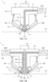
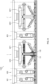
- the deposition system comprises a deposition head 100.
- the deposition head 100 at least includes a first deposition chamber 111 that is at least in part defined by a recess 115 in the main body and that extends to a first orifice 121 in the deposition face 101 (see dashed line) between at least two shutter elements 201, 202.
- the orifice can be reversibly opened and closed. Depending on a use condition, e.g. working pressure, the distance (or length) along which the orifice is opened can be tuned.
- a first pressurizing mechanism 141 and a drive unit 20 for providing relative motion between the deposition head and the workpiece in a direction transverse to the surface of the workpiece.
- Pressurizing mechanism 141 acts on the first deposition chamber and is configured to, in use, apply a first working pressure WP1 onto a printable medium 2 contained in the first deposition chamber.
- the system also includes a means for providing relative motion between the deposition head 100 and the workpiece in a lateral direction along the surface of the workpiece.
- Said means can be included in the system, e.g. as a conveyor.
- the drive unit 20 may be arranged to provide lateral motion.
- the deposition system may be used in combination with a further system, e.g. a production line, that already includes a conveying means.
- Said at least two shutter elements 201, 202 include a first shutter element 201.
- the first shutter element comprises a first blade 221 that extends from a first mount 211 towards an other 202 of the at the least two shutter elements so as to, in closed condition, close the first orifice 121 between terminal ends of the first blade and the other of the at least two shutter elements.
- Said first blade 221 is configured to flex in response to an applied first working pressure to at least partly open the first orifice 121. Opening the orifice, e.g. upon application of working pressure, allows the medium 2 to exit the deposition chamber and to flow towards the workpiece.
- the first shutter element 201 together with the other 202 of the at the least two shutter elements can be understood as a mechanism for reversibly closing and opening the deposition chamber.
- Providing the deposition system 1 with a closing mechanism advantageously mitigates spilling or leaking of printable medium 2 from the deposition head 100, e.g. onto non-target deposition areas on a workpiece, while the system is in an idle state. In idle condition the pressure on the printable medium 2 is kept relatively low, similar to ambient, so that the deposition chamber 111 stays closed.
- the shutter elements can be provided with a means to maintain a closed position by applying a closing force. Suitable means include but are not limited to springs, pneumatic cylinders, solenoids, etc.
- the drive unit 20 is arranged to, in use, adjust a relative position between the main body 110 and the surface of the workpiece to maintain a flush contact between the surface of the workpiece and the terminal ends of the first blade 221 and the other 202 of the at least two shutter elements while in a flexed condition. Maintaining a flush contact during a deposition run restricts a lateral flow of the printing medium along the surface of the working piece, e.g. beyond the blade.
- the other of the at least two shutter elements 202 comprises a further blade.
- Said further blade extends towards the terminal end of the first blade 221 from a corresponding mount provided to the main body opposite the first mount across the recess.
- said further blade is also configured to flex in response to an applied first working pressure so as to contribute to at least partly opening the first orifice 121.
- the other of the at least two shutter elements 202 can be a static shutter element, e.g. a protrusion such as a wall section or even an opposing edge of the recess 115.
- the first deposition chamber 111 can be understood to be closed off by a single blade.
- FIG 2 illustrates aspects of a deposition system in use to fill grooves 901 provided in the surface 902 of in a workpiece 900. So as to ease understanding some parts, such as the pressurizing mechanism, are not depicted.
- FIG 2A depicts a deposition head 100 while in idle condition.
- the first deposition chamber 111 is filled with printable medium 2.
- the orifice is in a closed conduction 121'.
- the deposition head 100 is moved in a direction "z" transverse to the surface 902 of the workpiece.
- the pressure on the ink 2 is kept relatively low so that the terminal ends of the first shutter element 201 and the other 202 of the at least two shutter elements remain in contact.
- a closing force CF is applied to assure the orifice is in a closed conduction 121'.
- the closing force if applied, is released and the pressure working pressure WP on the ink is increased so as to flex the blade and switch the orifice to an open condition 121.
- the control unit adjusts a vertical position so that the orifice can be opened while the terminal ends of the shutter elements remain in contact with the workpiece.
- the ink 2 can be forced into the groove.
- the resulting force including the pressure exerted onto the workpiece as the printable medium 2 is ejected from the orifice 121, will make the system want to lift from the workpiece.
- This is counteracted by the drive unit 20 by suitably adjusting a relative position between the main body and the surface of the workpiece so as to maintain a flush contact between the surface of the workpiece and the terminal ends of the first blade 221 and the other 202 of the at least two shutter elements while in a flexed condition.
- the drive is arranged to adjust the relative position between the main body and the surface of the workpiece in dependence of a measured force between the deposition head 100 and the workpiece.
- the system can be provided with a suitable force sensing means such as a force gauge 30 or pressure sensor.
- the output of said means can be used as control parameter to maintain the flush contact.
- the drive unit is further arranged to adjust an angle between the deposition head and the workpiece such as to maintain the flush contact, e.g. with a tilt, or ⁇ -stage.
- the flush contact is maintained as the head 100 is guided across the surface of the workpiece (lateral motion L). Provision of a flush contact, at least during a deposition run can be understood to contribute to confining a flow of the medium from the head into the groove, mitigating deposition of material outside the groove.
- the head 100 is retracted from the workpiece 900.
- the orifice is closed prior to breaking the flush contact. Closing the orifice may be attained by one or more of applying a closing force CF to the shutter elements and by applying a suitable under pressure. Closing the orifice prior to breaking the flush contact can, in particular for pasty products which are generally very sticky, mitigate deposition of residues as the head is pulled away from the workpiece.
- the applied working pressure depends on the viscosity of the printable medium 2 and/or on the geometry of the grooves that are to be filled and can be determined experimentally.
- High aspect ratio grooves typically require higher working pressure compared to low aspect ratio grooves.
- the applied working pressure can be as large as 7 bars or more, e.g. in a range between ambient and 6 bars or more, e.g. up to 10 bars or even more, e.g. up to 24 or 30 bars as possible with some syringe systems.
- An upper limit can be determined by a strength of the used shutter elements, e.g. the first blade.
- Heat can be provided to reduce the viscosity of the printable medium.
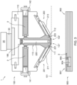
- the system comprises a heater 180 at a position so as to locally act on the printable medium 2 contained in the deposition chamber, e.g. as shown in FIGs 3 and 4 .
- Heating the printable medium 2 can reduce the viscosity of the ink and can accordingly increase a deposition rate at a given working pressure.
- the upper limit of the target temperature depends on the thermal stability of the printable medium, e.g. a boiling temperature and/or decomposition temperature of one or more of its constituents. For highly loaded paste the upper limit is typically between 80 and 100°C. Accordingly, the ink is typically heated to a temperature between 30 and about 100 °C, e.g. between 40 and 80°C or between 30 and 70 °C.
- the other 202 of the at least two shutter elements includes a separator wall 220.
- the separator wall 220 extends longitudinally through recess 115 to define a second deposition chamber 112 that is laterally separated from the first deposition chamber 111 by said separator wall 220, or in other words to define a dual chamber system.
- the first and second mount are typically provided along opposing edges of the recess 115, wherein each of the mounts covers a corresponding orifice.
- such dual chamber system further comprises a second pressurizing mechanism 142 that acts on the second deposition chamber, and that is configured to, in use, apply a second working pressure onto a printable medium contained in the second deposition chamber.
- said second deposition chamber 112 extends to a second orifice 122 in the deposition face 111 between the other 202 of the at least two shutter elements and a further shutter element 203.
- FIG 3 illustrates shutter elements in closed position, i.e. with the first orifice 121'and the second orifice 122' in closed condition.
- Said further shutter element 203 comprises a second blade 223 that extends from a corresponding second mount 213 that is provided to the main body 110 opposite the first mount 211 across the recess 115 towards the other of the at least two shutter elements 202 to close the second orifice between terminal ends of the second blade and the other of the at least two shutter elements in a closed condition.
- said second blade is preferably configured to flex in response to an applied second working pressure so as to at least partly open the first orifice.
- the dual chamber system advantageously provides two orifices from which medium can be deposited into a groove.
- the separator wall 220 separating the first and second deposition chambers advantageously allows application of a second working pressure which is essentially independent from the first working pressure and vice versa. Applying different working pressures was found to offer a number of benefits, which includes optimized filling.
- fill speed can be increased by increasing the working pressure.
- dual chamber systems advantageously allow more freedom in selection of working pressure that can be applied.
- a main aspect hereto is based on a realization that due to an experienced difference in flow resistance the functional paste 2 will flow more readily into wide grooves as opposed to narrow grooves.
- the means that, in particular for workpieces comprising a plurality of grooves with, a system operating under a single working pressure, can lead to uneven filling of grooves, e.g. wide grooves potentially being overfilled compared to narrow grooves. To mitigate this, e.g.
- provision of a dual chamber system can mitigate these aspects by using different working pressures in the chambers.
- the two chambers are passed sequentially across the groove.
- the first chamber, the leading chamber is operated at a comparatively high pressure, e.g. 6 bars overpressure, so as to at least provide an initial fill to a groove at a high deposition rate.
- the second chamber, the trailing chamber operates at a comparatively lower pressure, e.g. 1 bar overpressure, so as to complete the filling of the groove.
- the second blade, the trailing blade can function as a scraper controlling a fill.
- the orifices are spaced across a relatively short distance yet sufficiently far apart to allow simultaneous filling of a single groove from both orifices while operating under mutually different working pressures.
- Larger separation distance between first and second orifices improves decoupling of pressure (reduces coupling across the groove).
- a pressure drop between the two chambers can be reduced, e.g. via a percolation path along a groove to be filled, which may partly negate the benefits of using a dual chamber system.
- the area of the separator wall separating the chambers, as seen from the workpiece, preferably exceeds the cross-sectional area of the groove (as seen along the groove) by a factor of at least two, preferably by at least ten.
- the first and second orifice are laterally separated from each other by a distance more than a maximum depth of the grooves to be filled and less than a minimal lateral width a depth of the grooves to be filled.
- the separation distance is typically defined by the thickness of the separator wall.
- the separator wall has a width in a range between 1 and about 10 millimeters. Separator walls having a width in this range were found to reliably fill a broad range of grooves having dimensions in a relevant range.
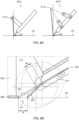
- each of the at least a first blade is positioned under an acute angle relative to the surface of the workpiece.
- the angle is a range from 15 to 60 degrees, most preferably in a range from 20 to 35 degrees. Angles in the specified ranges were found to offer a good balance between pressure applied onto the workpiece and confinement e.g. wiping or scraping of medium to be printed.
- the working pressure can in principle be adjusted over a broad range to affect a deposition rate. While not in flush contact with the workpiece increasingly high working pressures results in increasingly larger deflection of the blade, whereby the increasing outward displacement of the tip of the blade results in an increasing distance over which the orifice is opened. However, while already in flush contact, increasing the working pressure can result in increasing the contact pressure between tip and the workpiece. Increasing contact pressure can increase wear of blades and/or scratching the surface of the workpiece, e.g. during a lateral translation of the deposition head across the surface of the workpiece.
- the blades are preferably resilient blades so as to mitigate a need for frequent replacement of the blades.
- Blades formed of a plastic composition were found to offer a suitable combination of properties including strength, stiffness and toughness.
- Blades formed of a composition comprising a polyaryletherketone (PAEK) polymer such as PEK (polyetherketone), PEEK (polyether ether ketone), PEKK (poly(etherketonketone)), PEEKK (poly(etheretheretherketone)), PEKEKK (poly(etherketon-etherketonketone)) or mixtures thereof were found to be particularly suitable as such blades combine low friction (low-stick), suitable strength, stiffness and toughness.
- PAEK polyaryletherketone
- PEK polyaryletherketone
- PEKK poly(etherketonketone)
- PEEKK poly(etherketon-etherketonketone)
- PEKEKK poly(etherketon-etherketonketone
- the first mount is arranged to, in use, adjust a position and/or orientation of the first blade relative to the main body in dependence of at least the first working pressure.
- Adjusting a position and/or orientation of the first blade, relative to the main body can be understood to include providing a rotational and/or translation motion of the first blade relative to the main body.
- Adjusting a position and/or orientation of the first blade advantageously can be understood to constitute a means of opening and closing the closing mechanism, i.e. to contribute to controlling an opening width of the orifice, e.g. during a deposition procedure while maintaining flush contact with the workpiece.
- the deposition head 100 is used to deposit a conductive past 2, in grooves so as to form electrically conductive contact pads to contacts 905 of a buried electronic device 904.
- systems comprising a first mount that is arranged to, in use, adjust a position and/or orientation of the first blade relative to the main body in dependence of at least the first working pressure, allow maintaining the contact pressure below a predefined maximum contact pressure.
- the contact pressure between tip of the blade and workpiece is preferably kept below about 0.5 bar, preferably in range between 0.1 and 0.4 bar, most preferably about 0.2 or 0.3 bar.
- the device and in particular the first mount is preferably further arranged to in use adjust the position and/or orientation of the first blade in dependence of at least the first working pressure, so as to in use at least partly counteract said contact pressure between the terminal end of the first blade and the surface of the workpiece.
- Adjusting the position and/or orientation of the first blade in dependence of at least the first working pressure advantageously allows reducing the contact pressure, thus mitigating excess contact pressure between tip and workpiece.
- FIG 6A illustrates two embodiments of a first shutter element 201a and 201b.
- the mount is arranged to be rotatable around an axis 211a so that the tip of the blade can be pulled away from a closing position without imparting a motion of the tip end towards the workpiece, e.g. across the deposition face 101.
- the axis of rotation is provided near a terminal end of an arm extending beyond the tip of the blade.
- Embodiment 201b illustrates an alternative mount arranged to rotate along a virtual axis.
- the first mount 211 comprises a retracting mechanism arranged to, in use, retract the corresponding blade 211 in a direction along said blade.
- FIG 6B illustrates a mount with blade 221 in an idle position and in a position under operating conditions. In the idle position the blade contacts a terminal end of an opposing other shutter element 202. In the open position the blade is retracted by a distance RD to a retracted position 221'. Also illustrated is flexing of the blade in the retracted position under influence of a working pressure applied to an ink in the first deposition chamber 111.
- the blade is retracted in dependence of the applied working pressure so as to avoid motion of the tip of the blade across the deposition face 101, thus mitigating contact force between blade and workpiece while maintaining flush contact.
- the opening width W of the orifice depends on sliding distance and working pressure (flexing distance of the blade).
- sliding and/or rotational motion of the blade is controlled in dependence of pre-determined calibration values.
- the system includes a controller, e.g. a feedback controller, such as a force feedback controller acting on one or more of the first and second mounts to adjust a position and/or orientation of one or more of the terminal ends of the blade relative to the main body.
- the deposition system comprises a sliding element 260 that is provided at the terminal end of the other of the at least two shutter elements (the separator wall).
- the sliding element 260 extends along the deposition face 101 and is arranged to, in closed condition, contact terminal ends of the first and the second shutter elements (blades) along opposing terminal ends of said gliding element.
- the sliding element advantageously provides an elongate contact face for in use contacting and sliding along the surface of the workpiece.
- the sliding element can be understood to, in use, reduce a contact pressure between system and workpiece.
- the elongate contact face comprises, or is formed of, a low friction and/or wear resistant material, e.g. a coating, such as polymer composition comprising a polyfluorinated polymer such as polytetrafluoroethylene (PTFE), nylon, and/or polyaryletherketone (PAEK).
- blades typically have a thickness in a range between 0.5 and 3 millimeters and a length (arm) between mount and tip in a range from about 1.5 to 10 millimeters.
- FIG 7 illustrates bending of typical PEEK blades having a length (arm between mount and tip) between 2 and 7 millimeters in dependence of applied pressure at room temperature.
- FIG 7A depicts a determined flexing distance of the tip 'h' for PEEK blades with a thickness of 1 millimeter.
- FIG 7B illustrates bending of otherwise similar blades but having a thickness of 1.6 mm.
- flexing distance was found to scale linearly with the applied pressure.
- the highly predictable behavior was found even at elevated temperatures, such as the preferred operating temperatures as described above.
- the deposition system comprises an ultra-sonic transducer 185.
- Said transducer is preferably provided near the workpiece, e.g. at a terminal end of the separator wall or embedded therein, e.g. as shown in FIGs 4 and 5 .
- Positioning the ultra-sonic transducer near the workpieces allows the transducer to, in use, act on the printable medium deposited within the groove. Sonication can reduce bubble formation within the groove. More importantly, the transducer can contribute to a cleaning operation mode, as will be described in more detail in relation to a deposition system assembly as shown in FIG 8 .
- the disposition system as disclosed herein can also be used to deposit low viscosity inks and/or cleaning agents, including but not limited to organic solvents such as ethanol, propanol and acetone.
- Cleaning agents can advantageously be used to clean surfaces and/or grooves, in particular when combined with sonication.
- the solvent is preferably removed, e.g. sucked up, from the workpiece.
- a dual deposition chamber system can be used with this effect to particular benefit.
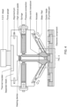
- FIG 8 Illustrated in FIG 8 is a system 1' in use to deposit a cleaning agent 2' from one of the first and the second deposition chambers and to at least partly recover said cleaning agent via the other of the first and the second deposition chambers.
- Depositing and subsequent removal of the cleaning agent 2' can be attained by applying a positive working pressure WP1' to one of the corresponding deposition chambers and applying an under pressure WP2' to the other of the corresponding deposition chambers.
- FIG 8 illustrates an exemplary assembly 1000.
- the assembly 1000 e.g. as shown, is arranged to subsequently deposit: a cleaning agent to clean the grooves provided within a surface of a workpiece; and a high solid content printable medium to fill said cleaned grooves.
- said system comprises at least two deposition systems as disclosed herein that are arranged in series. At least one, preferably both, of the systems is a dual deposition chamber system. Preferably, one of the systems is arranged to deposit and remove a cleaning agent. The other is arranged to deposit a printable medium 2, e.g. a high solid content paste, in the cleaned groove.
- the deposition system assembly can be provided with one or more cleaning systems, e.g. wiping systems 601, 602, 603, arranged to selectively remove at least part of an amount of printable medium deposited outside the grooves.
- the assembly can include one or more of a wiper or blower positioned between the cleaning and filling unit to remove remaining residues of cleaning agent 2' from the workpiece.
- the assembly can include one or more wipers to remove traces of printable medium 2 left on the of the workpiece at a landing/retraction position and/or a wiper arranged to remove traces of printable medium deposited along edges of the workpiece.
- the present disclosure relates to a method of depositing a printable medium in grooves and to s use of the disclosed system.
- the method of depositing a printable medium in grooves provided within a surface of a workpiece comprises at least the steps of: providing a deposition system as disclosed herein; applying a first working pressure onto a printable medium contained in the first deposition chamber to flex the first blade to at least partly open the first orifice, and providing a relative motion between the main body and the workpiece in a direction transverse to the surface of the workpiece so as to maintain a flush contact between the surface of the workpiece and the terminal ends of the first blade and the other of the at least two shutter elements; and the step of providing a relative motion between the deposition head and the workpiece in a lateral direction along the surface of the workpiece to guide the deposition head across the grooves.
- the system is of the dual chamber type. Accordingly, and in line with the description of such dual chamber systems, the method further comprises: applying a second working pressure onto a printable medium contained in the second deposition chamber to flex the second blade to at least partly open the second orifice while applying the second working pressure.
- the first working pressure is higher than the second working pressure if the first orifice is leading and the second orifice is trailing (as seen along the direction of lateral motion) when the deposition head is guided across the grooves, or wherein the second working pressure is higher than the first working pressure if the second orifice is leading and the first orifice is trailing.
- FIG 9 illustrates experimental results of exemplary grooves 901-1 to 901-4 provided in a workpiece filled using a dual chamber system as disclosed herein.
- first and second deposition chambers 111, 112 each filled with a printable medium having a viscosity of 1000 Pa.s and a thixotropic index of 4.
- the system is in flush contact with the workpiece. Other parts of the system such as the blades are omitted for ease of understanding.
- the system is moved across the workpieces at speed Vc in direction indicated by the corresponding arrow.
- the working pressure WP1 (P1) in the leading working chamber 111 is higher than the pressure WP2 (P2) in the trailing chamber 112.
- the system provided includes a first mount comprising a retracting mechanism arranged to in use retract the corresponding blade in a direction along said blade method according comprising.
- the method can be understood to include the step of retracting the first blade in a direction along said blade to at least partly counteract a contact pressure between the terminal end of the first blade and the surface of the workpiece.
- retracting the first blade can be understood to contribute to opening the orifice and to reducing a contact pressure between workpiece and blade.
- the methods include a step of closing the one or more orifices.
- Closing the orifice e.g. after completing a deposition cycle typically includes at least reducing the applied working pressure so as to stop ejecting of printable medium.
- the step of closing the one or more orifices comprises repositioning the first blade to an idle, closing position. Positioning the blade to a closing position typically comprises reversing a applied retraction distance.
- closing the orifice can include applying an under pressure to the corresponding working chamber. Independent of the type of material deposited, the step of closing the opened first and/or second orifice is preferably performed prior to breaking the flush contact.
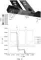
- FIG 10 illustrates a method of cleaning a groove.
- the top image depicts exemplary grooves being cleaned using a dual chamber system as disclosed herein.
- the system is moved across the surface of a workpiece in a direction indicated by the arrow while in flush contact therewith.
- the workpiece comprises 4 grooves 901-1 to 901-4 that are each initially filled with an uncured resin.
- the leading chamber 111 (operated at WP1 slightly above ambient) contains a cleaning agent.
- the trailing chamber 112 is operated at an under pressure WP2 at which the deposited leaning agent is sucked up and out of the grooves.
- the lower image shows a cross section along the groove indicating a filling level (fraction of resin) contained within the groove as the system passes along the groove. As can be seen from the traces the grooves can be effectively cleaned.
- FIG 11 depicts a photo of a workpiece 900 having filled grooves 901' that are about 250 ⁇ m wide and about 50 ⁇ m deep.
- the grooves (tracks) are filled with a conductive silver paste 2 (DuPontPE828).
- the grooves have approximately similar dimensions.
- a single chamber system was found well suited for filling the grooves.
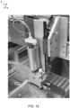
- FIG 12 depicts the test setup 1 as used.
- the setup comprises single chamber system of the type shown in FIG 1A , yet having a sliding mechanism as explained in relation to FIG 3 .
- the setup as shown includes a translation stage supporting a deposition head 100 while in contact with a workpiece 900. In case the workpiece would include groves with more variation in depth and/or width a dual chamber system can be more effective.
- the grooves were filled at a pass speed of 25 mm/s, using a pressure of 3 bar and at a temperature of 20 °C.
- the blades are formed of PEEK and have a length and thickness of respectively 6 and 1 millimeters. As explained in relation to FIG 7A , the blades have a deflection of about 150 ⁇ m under these conditions. As can be observed, the surface directly next to the grooves remains exceptionally clean, which is an indication that the scraper blade is performing as expected. As can be seen for this particular setup, some material was deposited along the edges of the head, which can be removed, e.g. by wiper systems and/or by improving seals along terminal bounds of the deposition heads.
- the filled tracks contact a bare die chip (50 ⁇ m thickness) embedded in a 3D print. After curing the paste at a temperature of 100°C for 5 minutes all interconnects were found to be fully functional.
Landscapes
- Engineering & Computer Science (AREA)
- Manufacturing & Machinery (AREA)
- Chemical & Material Sciences (AREA)
- Materials Engineering (AREA)
- Microelectronics & Electronic Packaging (AREA)
- Coating Apparatus (AREA)
- Screen Printers (AREA)
Claims (13)
- Ein Abscheidesystem (1) zum Abscheiden eines druckbaren Mediums (2) in einer Nut (901) innerhalb einer Oberfläche (902) eines Werkstücks (900), wobei das Abscheidesystem (1) umfasst: einen Abscheidekopf (100) einschließlich einer Abscheidefläche (101); und eine Antriebseinheit (20) zum Bereitstellen einer relativen Bewegung zwischen dem Abscheidekopf (100) und dem Werkstück (900) in einer Richtung quer zur Oberfläche (902) des Werkstücks (900);
den Abscheidekopf (100) umfassend:einen Hauptkörper (110), der wenigstens eine erste Abscheidekammer (111) umfasst, die wenigstens teilweise durch eine Aussparung (115) im Hauptkörper (110) definiert ist und sich bis zu einer ersten Öffnung (121) in der Abscheidefläche (101) zwischen wenigstens zwei Verschlusselementen (201, 202) erstreckt; undeinen ersten Druckbeaufschlagungsmechanismus (141), der auf die erste Abscheidekammer wirkt und so eingerichtet ist, dass er im Gebrauch einen ersten Arbeitsdruck (WP1) auf das in der ersten Abscheidekammer enthaltene druckbare Medium (2) ausübt; undwenigstens eine erste Aufnahme (211), die dem Hauptkörper (110) bereitgestellt ist;die wenigstens zwei Verschlusselemente (201, 202), einschließlich eines ersten Verschlusselements (201), das eine erste Klinge (221) umfasst, die sich von der ersten Aufnahme (211) zu einem anderen (202) der wenigstens zwei Verschlusselemente (201, 202) erstreckt, um die erste Öffnung (121) zwischen den Abschlussenden der ersten Klinge (221) und dem anderen der wenigstens zwei Verschlusselemente (201, 202) in geschlossenem Zustand zu verschließen,die erste Klinge (221), die so eingerichtet ist, dass sie sich als Reaktion auf einen angelegten ersten Arbeitsdruck (WP1) biegt, um die erste Öffnung (121) zumindest teilweise zu öffnen; undwobei die Antriebseinheit (20) so angeordnet ist, dass sie im Gebrauch eine relative Position zwischen dem Hauptkörper (110) und der Oberfläche (902) des Werkstücks (900) einstellt, um in einem gebogenen Zustand einen bündigen Kontakt zwischen der Oberfläche (902) des Werkstücks (900) und den Abschlussenden der ersten Klinge (221) und des anderen der wenigstens zwei Verschlusselemente (201, 202) aufrechtzuerhalten; undwobei die erste Aufnahme (211) so angeordnet ist, dass sie im Gebrauch eine Position und/oder Ausrichtung der ersten Klinge (221) relativ zum Hauptkörper (110) in Abhängigkeit zumindest des ersten Arbeitsdrucks (WP 1) einstellt, sodass im Gebrauch zumindest teilweise einem Kontaktdruck zwischen dem Abschlussende der ersten Klinge (221) und der Oberfläche (902) des Werkstücks (900) entgegengewirkt wird, sodass im Gebrauch ein bündiger Kontakt zwischen der Oberfläche (902) des Werkstücks (900) und den Abschlussenden der ersten Klinge (221) und dem anderen der wenigstens zwei Verschlusselemente (201, 202) aufrechterhalten wird; und/oderwobei das andere der wenigstens zwei Verschlusselemente (201, 202) eine sich längs durch die Aussparung (115) erstreckende Trennwand einschließt, um eine zweite, seitlich von der ersten Abscheidekammer getrennte Abscheidekammer (112) zu definieren,sich die zweite Abscheidekammer (112) bis zu einer zweiten Öffnung (122) in der Abscheidefläche (101) zwischen dem anderen der wenigstens zwei Verschlusselemente (201, 202) und einem weiteren Verschlusselement erstreckt,das weitere Verschlusselement eine zweite Klinge (223) umfasst, die sich von einer entsprechenden zweiten Aufnahme, die am Hauptkörper (110) gegenüber der ersten Aufnahme (211) vorgesehen ist, über die Aussparung (115) zum anderen der wenigstens zwei Verschlusselemente (201, 202) hin erstreckt, um die zweite Öffnung (122) zwischen den Abschlussenden der zweiten Klinge (223) und dem anderen der wenigstens zwei Verschlusselemente (201, 202) in geschlossenem Zustand zu verschließen,das Abscheidesystem (1) ferner einen zweiten Druckbeaufschlagungsmechanismus (32) umfasst, der auf die zweite Abscheidekammer (112) wirkt und so eingerichtet ist, dass er im Gebrauch einen zweiten Arbeitsdruck (WP2) auf ein in der zweiten Abscheidekammer (112) enthaltenes druckbares Medium (2) ausübt, wobei die zweite Klinge (223) so eingerichtet ist, dass sie sich als Reaktion auf einen angelegten zweiten Arbeitsdruck (WP2) biegt, um die zweite Öffnung (122) zumindest teilweise zu öffnen. - Abscheidesystem (1) nach Patentanspruch 1, wobei die erste Aufnahme (211) einen Rückzugsmechanismus umfasst, der dazu eingerichtet ist, die entsprechende Klinge in einer Richtung entlang der Klinge zurückzuziehen.
- Abscheidesystem (1) nach einem der Patentansprüche 1 bis 2, ferner umfassend ein Schiebeelement (260), das am Abschlussende des anderen der wenigstens zwei Verschlusselemente (201, 202) vorgesehen ist und sich entlang der Abscheidefläche (101) erstreckt und so angeordnet ist, dass es im geschlossenen Zustand Abschlussenden der ersten (221) und der zweiten Klinge (223) entlang gegenüberliegender Abschlussenden des Schiebeelements berührt, wobei das Schiebeelement eine längliche Kontaktfläche bereitstellt zum Kontaktieren bei Benutzung und Schieben entlang der Oberfläche (902) des Werkstücks (900) zwischen zur Bereitstellung zwischen mindestens zwei ersten und einer zweiten zwischen den zumindest teilweise geöffneten ersten (121) und zweiten Öffnungen (122).
- Abscheidesystem (1) nach einem der Patentansprüche 1 bis 3, wobei die erste und zweite Öffnung (122) seitlich durch einen Abstand in einem Bereich zwischen 1 und 10 Millimetern voneinander getrennt sind.
- Abscheidesystem nach einem der Patentansprüche 1 bis 4, das dazu eingerichtet ist, ein Reinigungsmittel aus einer der ersten (141) und der zweiten (142) Abscheidekammern abzuscheiden und wenigstens teilweise das Reinigungsmittel über die andere der ersten (141) und der zweiten (142) Abscheidekammern zurückzugewinnen, indem ein positiver Arbeitsdruck auf eine der entsprechenden Abscheidekammern und ein Unterdruck auf die andere der entsprechenden Abscheidekammern ausgeübt wird.
- Abscheidesystem (1) nach Patentanspruch 1, wobei das andere der wenigstens zwei Verschlusselemente (201, 202) eine weitere Klinge umfasst, das sich von einer am Hauptkörper (110) gegenüber der ersten Aufnahme (211) quer über die Aussparung (115) vorgesehenen entsprechenden Aufnahme zum Abschlussende der ersten Klinge (221) erstreckt.
- Abscheidesystembaugruppe (1000), umfassend wenigstens ein Abscheidesystem (1) nach einem der vorhergehenden Patentansprüche und wenigstens ein Abscheidesystem (1) nach Patentanspruch 6, angeordnet zum anschließenden Abscheiden: eines Reinigungsmittels zum Reinigen der Nuten (901) innerhalb einer Oberfläche (902) eines Werkstücks (900); und eines druckbaren Mediums (2) mit hohem Feststoffgehalt zum Füllen der gereinigten Nuten (901).
- Verfahren zum Abscheiden eines druckbaren Mediums (2) in Nuten (901) innerhalb einer Oberfläche (902) eines Werkstücks (900) durch ein Abscheidesystem (1) nach einem der Patentansprüche 1 bis 7, wobei das Verfahren die Schritte umfasst:Aufbringen eines ersten Arbeitsdrucks (WP1) auf ein in der ersten Abscheidekammer (141) enthaltenes druckbares Medium (2), um die erste Klinge (221) zu biegen, um die erste Öffnung (121) zumindest teilweise zu öffnen, während eine relative Bewegung zwischen dem Hauptkörper (110) und dem Werkstück (900) in einer Richtung quer zur Oberfläche (902) des Werkstücks (900) bereitgestellt wird, sodass ein bündiger Kontakt zwischen der Oberfläche (902) des Werkstücks (900) und den Abschlussenden der ersten Klinge (221) und dem anderen der wenigstens zwei Verschlusselemente (201, 202) aufrechterhalten wird; undBereitstellung einer relativen Bewegung zwischen dem Abscheidekopf (100) und dem Werkstück (900) in einer seitlichen Richtung entlang der Oberfläche (902) des Werkstücks (900), um den Abscheidekopf (100) über die Nuten (901) zu führen.
- Verfahren nach Patentanspruch 8, wobei das Abscheidesystem (1) nach einem der Patentansprüche 1 bis 6 besteht, ferner umfassend:Aufbringen eines zweiten Arbeitsdrucks (WP2) auf ein in der zweiten Abscheidekammer (112) enthaltenes druckbares Medium (2), um die zweite Klinge (223) zu biegen, um die zweite Öffnung (122) während des Aufbringens des zweiten Arbeitsdrucks (WP2) wenigstens teilweise zu öffnen,wobei der erste Arbeitsdruck (WP1) höher als der zweite Arbeitsdruck (WP2) ist, wenn die erste Öffnung (121) voreilend und die zweite Öffnung (122) nacheilend ist [entlang der Seitenbewegungsrichtung gesehen], wenn der Abscheidekopf (100) über die Nuten (901) geführt wird, oder wobei der zweite Arbeitsdruck (WP2) höher als der erste Arbeitsdruck (WP1) ist, wenn die zweite Öffnung (122) voreilend und die erste Öffnung (121) nacheilend ist.
- Verfahren nach einem der Patentansprüche 9, wobei das Abscheidesystem (1) einem der Patentansprüche 2 bis 6 entspricht, wobei das Verfahren umfasst:
Zurückziehen der ersten Klinge (221) in einer Richtung entlang der Klinge, um wenigstens teilweise einem Kontaktdruck zwischen dem Abschlussende der ersten Klinge (221) und der Oberfläche (902) des Werkstücks (900) entgegenzuwirken. - Verfahren nach Patentanspruch 10, wobei das Abscheidesystem (1) dem Patentanspruch 5 entspricht, und wobei das druckbare Medium (2) ein Reinigungsmittel ist, das ferner das Anlegen eines zweiten Arbeitsdrucks (WP2) umfasst, der unter Druck an der zweiten Abscheidekammer (112) steht, während der erste Arbeitsdruck (WP1) angelegt wird, um wenigstens einen Teil des Reinigungsmittels zurückzugewinnen.
- Verfahren nach einem der Patentansprüche 8 bis 11, umfassend einen Schritt des Schließens der wenigstens teilweise geöffneten ersten (121) und/oder zweiten Öffnung (122) vor dem Brechen des bündigen Kontakts.
- Verwendung des Systems nach Patentanspruch 5 zum Entfernen von löslichen oder adsorbierten Stoffen aus einem Werkstück (900), wobei die Verwendung umfasst:
Abscheiden eines druckfähigen Mediums (2), das ein für den Stoff geeignetes Reinigungsmittel ist, auf das Werkstück (900) aus der ersten Abscheidekammer durch Anlegen eines geeigneten ersten Arbeitsdrucks (WP1) und Zurückgewinnen wenigstens eines Teils des abgesetzten druckfähigen Mediums (2) über die zweite Abscheidekammer (112) durch Anlegen eines geeigneten zweiten Arbeitsdrucks (WP2).
Applications Claiming Priority (2)
| Application Number | Priority Date | Filing Date | Title |
|---|---|---|---|
| EP20203659.6A EP3988312A1 (de) | 2020-10-23 | 2020-10-23 | Vorrichtung und verfahren zum füllen von nuten |
| PCT/NL2021/050641 WO2022086331A1 (en) | 2020-10-23 | 2021-10-22 | Device and method of filling grooves |
Publications (3)
| Publication Number | Publication Date |
|---|---|
| EP4232286A1 EP4232286A1 (de) | 2023-08-30 |
| EP4232286C0 EP4232286C0 (de) | 2024-08-28 |
| EP4232286B1 true EP4232286B1 (de) | 2024-08-28 |
Family
ID=73138608
Family Applications (2)
| Application Number | Title | Priority Date | Filing Date |
|---|---|---|---|
| EP20203659.6A Withdrawn EP3988312A1 (de) | 2020-10-23 | 2020-10-23 | Vorrichtung und verfahren zum füllen von nuten |
| EP21798467.3A Active EP4232286B1 (de) | 2020-10-23 | 2021-10-22 | Vorrichtung und verfahren zum füllen von nuten |
Family Applications Before (1)
| Application Number | Title | Priority Date | Filing Date |
|---|---|---|---|
| EP20203659.6A Withdrawn EP3988312A1 (de) | 2020-10-23 | 2020-10-23 | Vorrichtung und verfahren zum füllen von nuten |
Country Status (6)
| Country | Link |
|---|---|
| US (1) | US12365004B2 (de) |
| EP (2) | EP3988312A1 (de) |
| JP (1) | JP7769698B2 (de) |
| CN (1) | CN116761680B (de) |
| TW (1) | TW202216472A (de) |
| WO (1) | WO2022086331A1 (de) |
Families Citing this family (3)
| Publication number | Priority date | Publication date | Assignee | Title |
|---|---|---|---|---|
| US20240181704A1 (en) * | 2022-12-01 | 2024-06-06 | Vulcanforms Inc. | Powder hopper for additive manufacturing system |
| CN117485022A (zh) * | 2023-11-17 | 2024-02-02 | 常州纺织服装职业技术学院 | 一种版画机 |
| CN121082516B (zh) * | 2025-11-13 | 2026-01-16 | 北青(江苏)环境装备有限公司 | 用于浮盘蜂窝芯安装的胶水涂布装置 |
Family Cites Families (25)
| Publication number | Priority date | Publication date | Assignee | Title |
|---|---|---|---|---|
| JP3099447B2 (ja) * | 1991-09-02 | 2000-10-16 | 松下電器産業株式会社 | 塗布装置及び方法並びに印刷装置及び方法 |
| US6286422B1 (en) | 1994-12-27 | 2001-09-11 | Visteon Global Tech., Inc. | Method and apparatus for dispensing viscous material |
| DE69737281T2 (de) * | 1996-12-10 | 2007-12-20 | Matsushita Electric Industrial Co., Ltd., Kadoma | Vorrichtung und Verfahren zum Drucken von Lötpaste |
| JP2981875B2 (ja) * | 1997-03-14 | 1999-11-22 | 井上金属工業株式会社 | 塗工装置 |
| US5947022A (en) * | 1997-11-07 | 1999-09-07 | Speedline Technologies, Inc. | Apparatus for dispensing material in a printer |
| JP2000062138A (ja) * | 1998-08-19 | 2000-02-29 | Matsushita Electric Ind Co Ltd | 印刷装置 |
| JP2000141599A (ja) | 1998-11-16 | 2000-05-23 | Hitachi Techno Eng Co Ltd | 圧入ヘッドを備えた印刷機 |
| GB2351259A (en) | 1999-06-22 | 2000-12-27 | Dek Printing Machines Ltd | Blades for screen printing |
| GB2352209A (en) | 1999-07-19 | 2001-01-24 | Dek Printing Machines Ltd | Improvements relating to screen printing |
| US6276270B1 (en) | 1999-08-20 | 2001-08-21 | Interflex, L.L.C. | Ink distributton apparatus and method for anilox roll |
| DE10001392A1 (de) * | 2000-01-14 | 2001-07-19 | Voith Paper Patent Gmbh | Auftragsvorrichtung |
| EP1331094A1 (de) * | 2000-11-02 | 2003-07-30 | The Furukawa Electric Co., Ltd. | Druckrakel und sruckvorrichtung für weichlotpaste |
| US20020152904A1 (en) | 2001-04-23 | 2002-10-24 | Pascal Ross | Doctor blade design for metering ink transfer to anilox cells |
| US7096781B2 (en) * | 2002-05-29 | 2006-08-29 | Tani Denkikogyo Co., Ltd. | Screen printing apparatus having paste chamber with discharge opening and structure for introducing paste residue from previous printing into discharge opening |
| JP2004079584A (ja) | 2002-08-09 | 2004-03-11 | Noda Screen:Kk | 樹脂充填装置 |
| CN100460208C (zh) | 2004-01-14 | 2009-02-11 | 东海商事株式会社 | 电子部件的印刷装置和制造方法 |
| US7249558B2 (en) * | 2004-07-15 | 2007-07-31 | Speedline Technologies, Inc. | Solder paste dispenser for a stencil printer |
| JP2007106103A (ja) | 2005-09-16 | 2007-04-26 | Nippon Paint Co Ltd | 印刷方法およびそのための装置 |
| GB2437070B (en) | 2006-04-10 | 2011-12-14 | Dek Int Gmbh | Screen printing head and system |
| WO2008127726A1 (en) | 2007-04-13 | 2008-10-23 | Winterlab Limited | System and method for determining the kosher status of fish |
| WO2011017222A2 (en) | 2009-08-04 | 2011-02-10 | Applied Materials, Inc. | Method and apparatus for dry cleaning a cooled showerhead |
| JP5408159B2 (ja) | 2011-03-09 | 2014-02-05 | パナソニック株式会社 | スクリーン印刷装置およびスクリーン印刷方法 |
| US8939073B2 (en) * | 2012-02-08 | 2015-01-27 | Illinois Tool Works Inc. | Print head for stencil printer |
| JP6389695B2 (ja) | 2014-08-18 | 2018-09-12 | 理想科学工業株式会社 | 感熱製版装置 |
| JP7113164B2 (ja) | 2017-09-27 | 2022-08-05 | パナソニックIpマネジメント株式会社 | 印刷装置 |
-
2020
- 2020-10-23 EP EP20203659.6A patent/EP3988312A1/de not_active Withdrawn
-
2021
- 2021-10-21 TW TW110139130A patent/TW202216472A/zh unknown
- 2021-10-22 EP EP21798467.3A patent/EP4232286B1/de active Active
- 2021-10-22 WO PCT/NL2021/050641 patent/WO2022086331A1/en not_active Ceased
- 2021-10-22 CN CN202180076992.4A patent/CN116761680B/zh active Active
- 2021-10-22 US US18/032,905 patent/US12365004B2/en active Active
- 2021-10-22 JP JP2023524805A patent/JP7769698B2/ja active Active
Also Published As
| Publication number | Publication date |
|---|---|
| CN116761680B (zh) | 2025-07-01 |
| US20230398565A1 (en) | 2023-12-14 |
| JP2023546702A (ja) | 2023-11-07 |
| CN116761680A (zh) | 2023-09-15 |
| TW202216472A (zh) | 2022-05-01 |
| WO2022086331A1 (en) | 2022-04-28 |
| JP7769698B2 (ja) | 2025-11-13 |
| EP4232286C0 (de) | 2024-08-28 |
| EP3988312A1 (de) | 2022-04-27 |
| EP4232286A1 (de) | 2023-08-30 |
| US12365004B2 (en) | 2025-07-22 |
Similar Documents
| Publication | Publication Date | Title |
|---|---|---|
| EP4232286B1 (de) | Vorrichtung und verfahren zum füllen von nuten | |
| CN1158155C (zh) | 在印刷机中用来分配材料的方法和器械 | |
| US12358227B2 (en) | Fluid management and circulation systems for use in additive manufacturing apparatuses | |
| EP0913263B1 (de) | Zurückziehbare Wischerreinigungsvorrichtung für Tintenstrahldruckköpfe | |
| EP3972758B1 (de) | Reinigungsstation und verfahren zur reinigung eines druckkopfes | |
| US12097709B2 (en) | Cleaning fluids for use in additive manufacturing apparatuses and methods for monitoring status and performance of the same | |
| JP2004338372A (ja) | インクジェットプリンター用ワイパー組立体 | |
| US12280596B2 (en) | Cleaning systems for additive manufacturing apparatuses and methods for using the same | |
| US20220234295A1 (en) | Wet wiper apparatuses for use in additive manufacturing apparatuses | |
| JP3834049B2 (ja) | インクジェット式記録装置、インクジェットヘッド部のクリーニング装置および、インクジェットヘッド部のクリーニング方法 | |
| JP2004338371A (ja) | インクジェットプリンター用のコートされたワイパー | |
| JP4942138B2 (ja) | ヘッド清浄化方法およびインクジェット記録装置 | |
| CN1931582B (zh) | 液体吐出装置 | |
| CN100559916C (zh) | 在印刷电路板上用粘性物填充道间或凹入区的方法和设备 | |
| JP2019162839A (ja) | 液体吐出ヘッド | |
| JP6289357B2 (ja) | フッ素化オルガノシロキサン網目構造組成物 | |
| CN219816821U (zh) | 一种防水板涂胶装置 | |
| JP4198831B2 (ja) | 粘性材料塗布方法 | |
| JP7830565B2 (ja) | インクジェット記録方法、及びインクジェット記録装置 | |
| CN221086212U (zh) | 一种自粘卷材胶层涂布机构 | |
| US12138858B2 (en) | Systems and methods for continuous flow control of printable material in additive manufacturing | |
| Bennett et al. | Profiled Squeegee Blade: Rewrites the Rules for Angle of Attack | |
| JP4799331B2 (ja) | インクジェットヘッドの清浄化方法およびインクジェット記録装置 | |
| KR20080043575A (ko) | 인쇄 장치 | |
| JP2009113224A (ja) | インクジェットヘッドユニット |
Legal Events
| Date | Code | Title | Description |
|---|---|---|---|
| STAA | Information on the status of an ep patent application or granted ep patent |
Free format text: STATUS: UNKNOWN |
|
| STAA | Information on the status of an ep patent application or granted ep patent |
Free format text: STATUS: THE INTERNATIONAL PUBLICATION HAS BEEN MADE |
|
| PUAI | Public reference made under article 153(3) epc to a published international application that has entered the european phase |
Free format text: ORIGINAL CODE: 0009012 |
|
| STAA | Information on the status of an ep patent application or granted ep patent |
Free format text: STATUS: REQUEST FOR EXAMINATION WAS MADE |
|
| 17P | Request for examination filed |
Effective date: 20230421 |
|
| AK | Designated contracting states |
Kind code of ref document: A1 Designated state(s): AL AT BE BG CH CY CZ DE DK EE ES FI FR GB GR HR HU IE IS IT LI LT LU LV MC MK MT NL NO PL PT RO RS SE SI SK SM TR |
|
| P01 | Opt-out of the competence of the unified patent court (upc) registered |
Effective date: 20230901 |
|
| DAV | Request for validation of the european patent (deleted) | ||
| DAX | Request for extension of the european patent (deleted) | ||
| GRAP | Despatch of communication of intention to grant a patent |
Free format text: ORIGINAL CODE: EPIDOSNIGR1 |
|
| STAA | Information on the status of an ep patent application or granted ep patent |
Free format text: STATUS: GRANT OF PATENT IS INTENDED |
|
| INTG | Intention to grant announced |
Effective date: 20240327 |
|
| GRAS | Grant fee paid |
Free format text: ORIGINAL CODE: EPIDOSNIGR3 |
|
| GRAA | (expected) grant |
Free format text: ORIGINAL CODE: 0009210 |
|
| STAA | Information on the status of an ep patent application or granted ep patent |
Free format text: STATUS: THE PATENT HAS BEEN GRANTED |
|
| AK | Designated contracting states |
Kind code of ref document: B1 Designated state(s): AL AT BE BG CH CY CZ DE DK EE ES FI FR GB GR HR HU IE IS IT LI LT LU LV MC MK MT NL NO PL PT RO RS SE SI SK SM TR |
|
| REG | Reference to a national code |
Ref country code: CH Ref legal event code: EP |
|
| REG | Reference to a national code |
Ref country code: DE Ref legal event code: R096 Ref document number: 602021018049 Country of ref document: DE |
|
| REG | Reference to a national code |
Ref country code: IE Ref legal event code: FG4D |
|
| U01 | Request for unitary effect filed |
Effective date: 20240927 |
|
| P04 | Withdrawal of opt-out of the competence of the unified patent court (upc) registered |
Free format text: CASE NUMBER: APP_57499/2024 Effective date: 20241021 |
|
| U07 | Unitary effect registered |
Designated state(s): AT BE BG DE DK EE FI FR IT LT LU LV MT NL PT RO SE SI Effective date: 20241024 |
|
| U20 | Renewal fee for the european patent with unitary effect paid |
Year of fee payment: 4 Effective date: 20241025 |
|
| PG25 | Lapsed in a contracting state [announced via postgrant information from national office to epo] |
Ref country code: NO Free format text: LAPSE BECAUSE OF FAILURE TO SUBMIT A TRANSLATION OF THE DESCRIPTION OR TO PAY THE FEE WITHIN THE PRESCRIBED TIME-LIMIT Effective date: 20241128 |
|
| PG25 | Lapsed in a contracting state [announced via postgrant information from national office to epo] |
Ref country code: GR Free format text: LAPSE BECAUSE OF FAILURE TO SUBMIT A TRANSLATION OF THE DESCRIPTION OR TO PAY THE FEE WITHIN THE PRESCRIBED TIME-LIMIT Effective date: 20241129 Ref country code: PL Free format text: LAPSE BECAUSE OF FAILURE TO SUBMIT A TRANSLATION OF THE DESCRIPTION OR TO PAY THE FEE WITHIN THE PRESCRIBED TIME-LIMIT Effective date: 20240828 |
|
| PG25 | Lapsed in a contracting state [announced via postgrant information from national office to epo] |
Ref country code: IS Free format text: LAPSE BECAUSE OF FAILURE TO SUBMIT A TRANSLATION OF THE DESCRIPTION OR TO PAY THE FEE WITHIN THE PRESCRIBED TIME-LIMIT Effective date: 20241228 |
|
| PG25 | Lapsed in a contracting state [announced via postgrant information from national office to epo] |
Ref country code: HR Free format text: LAPSE BECAUSE OF FAILURE TO SUBMIT A TRANSLATION OF THE DESCRIPTION OR TO PAY THE FEE WITHIN THE PRESCRIBED TIME-LIMIT Effective date: 20240828 |
|
| PG25 | Lapsed in a contracting state [announced via postgrant information from national office to epo] |
Ref country code: ES Free format text: LAPSE BECAUSE OF FAILURE TO SUBMIT A TRANSLATION OF THE DESCRIPTION OR TO PAY THE FEE WITHIN THE PRESCRIBED TIME-LIMIT Effective date: 20240828 Ref country code: RS Free format text: LAPSE BECAUSE OF FAILURE TO SUBMIT A TRANSLATION OF THE DESCRIPTION OR TO PAY THE FEE WITHIN THE PRESCRIBED TIME-LIMIT Effective date: 20241128 |
|
| PG25 | Lapsed in a contracting state [announced via postgrant information from national office to epo] |
Ref country code: RS Free format text: LAPSE BECAUSE OF FAILURE TO SUBMIT A TRANSLATION OF THE DESCRIPTION OR TO PAY THE FEE WITHIN THE PRESCRIBED TIME-LIMIT Effective date: 20241128 Ref country code: PL Free format text: LAPSE BECAUSE OF FAILURE TO SUBMIT A TRANSLATION OF THE DESCRIPTION OR TO PAY THE FEE WITHIN THE PRESCRIBED TIME-LIMIT Effective date: 20240828 Ref country code: NO Free format text: LAPSE BECAUSE OF FAILURE TO SUBMIT A TRANSLATION OF THE DESCRIPTION OR TO PAY THE FEE WITHIN THE PRESCRIBED TIME-LIMIT Effective date: 20241128 Ref country code: IS Free format text: LAPSE BECAUSE OF FAILURE TO SUBMIT A TRANSLATION OF THE DESCRIPTION OR TO PAY THE FEE WITHIN THE PRESCRIBED TIME-LIMIT Effective date: 20241228 Ref country code: HR Free format text: LAPSE BECAUSE OF FAILURE TO SUBMIT A TRANSLATION OF THE DESCRIPTION OR TO PAY THE FEE WITHIN THE PRESCRIBED TIME-LIMIT Effective date: 20240828 Ref country code: GR Free format text: LAPSE BECAUSE OF FAILURE TO SUBMIT A TRANSLATION OF THE DESCRIPTION OR TO PAY THE FEE WITHIN THE PRESCRIBED TIME-LIMIT Effective date: 20241129 Ref country code: ES Free format text: LAPSE BECAUSE OF FAILURE TO SUBMIT A TRANSLATION OF THE DESCRIPTION OR TO PAY THE FEE WITHIN THE PRESCRIBED TIME-LIMIT Effective date: 20240828 |
|
| PG25 | Lapsed in a contracting state [announced via postgrant information from national office to epo] |
Ref country code: SM Free format text: LAPSE BECAUSE OF FAILURE TO SUBMIT A TRANSLATION OF THE DESCRIPTION OR TO PAY THE FEE WITHIN THE PRESCRIBED TIME-LIMIT Effective date: 20240828 |
|
| PG25 | Lapsed in a contracting state [announced via postgrant information from national office to epo] |
Ref country code: CZ Free format text: LAPSE BECAUSE OF FAILURE TO SUBMIT A TRANSLATION OF THE DESCRIPTION OR TO PAY THE FEE WITHIN THE PRESCRIBED TIME-LIMIT Effective date: 20240828 |
|
| PG25 | Lapsed in a contracting state [announced via postgrant information from national office to epo] |
Ref country code: SK Free format text: LAPSE BECAUSE OF FAILURE TO SUBMIT A TRANSLATION OF THE DESCRIPTION OR TO PAY THE FEE WITHIN THE PRESCRIBED TIME-LIMIT Effective date: 20240828 |
|
| REG | Reference to a national code |
Ref country code: CH Ref legal event code: PL |
|
| PLBE | No opposition filed within time limit |
Free format text: ORIGINAL CODE: 0009261 |
|
| STAA | Information on the status of an ep patent application or granted ep patent |
Free format text: STATUS: NO OPPOSITION FILED WITHIN TIME LIMIT |
|
| PG25 | Lapsed in a contracting state [announced via postgrant information from national office to epo] |
Ref country code: MC Free format text: LAPSE BECAUSE OF FAILURE TO SUBMIT A TRANSLATION OF THE DESCRIPTION OR TO PAY THE FEE WITHIN THE PRESCRIBED TIME-LIMIT Effective date: 20240828 |
|
| PG25 | Lapsed in a contracting state [announced via postgrant information from national office to epo] |
Ref country code: CH Free format text: LAPSE BECAUSE OF NON-PAYMENT OF DUE FEES Effective date: 20241031 |
|
| 26N | No opposition filed |
Effective date: 20250530 |
|
| PG25 | Lapsed in a contracting state [announced via postgrant information from national office to epo] |
Ref country code: IE Free format text: LAPSE BECAUSE OF NON-PAYMENT OF DUE FEES Effective date: 20241022 |
|
| U20 | Renewal fee for the european patent with unitary effect paid |
Year of fee payment: 5 Effective date: 20251028 |
|
| PGFP | Annual fee paid to national office [announced via postgrant information from national office to epo] |
Ref country code: GB Payment date: 20251022 Year of fee payment: 5 |
|
| U1H | Name or address of the proprietor changed after the registration of the unitary effect |
Owner name: NEDERLANDSE ORGANISATIE VOOR TOEGEPAST-NATUURWETENSCHAPPELIJK ONDERZOEK TNO; NL |
|
| PG25 | Lapsed in a contracting state [announced via postgrant information from national office to epo] |
Ref country code: CY Free format text: LAPSE BECAUSE OF FAILURE TO SUBMIT A TRANSLATION OF THE DESCRIPTION OR TO PAY THE FEE WITHIN THE PRESCRIBED TIME-LIMIT; INVALID AB INITIO Effective date: 20211022 |
|
| PG25 | Lapsed in a contracting state [announced via postgrant information from national office to epo] |
Ref country code: HU Free format text: LAPSE BECAUSE OF FAILURE TO SUBMIT A TRANSLATION OF THE DESCRIPTION OR TO PAY THE FEE WITHIN THE PRESCRIBED TIME-LIMIT; INVALID AB INITIO Effective date: 20211022 |