EP4231509B1 - Statorgehäuse - Google Patents
Statorgehäuse Download PDFInfo
- Publication number
- EP4231509B1 EP4231509B1 EP22157518.6A EP22157518A EP4231509B1 EP 4231509 B1 EP4231509 B1 EP 4231509B1 EP 22157518 A EP22157518 A EP 22157518A EP 4231509 B1 EP4231509 B1 EP 4231509B1
- Authority
- EP
- European Patent Office
- Prior art keywords
- housing
- section
- radial
- shaped
- radial ring
- Prior art date
- Legal status (The legal status is an assumption and is not a legal conclusion. Google has not performed a legal analysis and makes no representation as to the accuracy of the status listed.)
- Active
Links
Images


Classifications
-
- H—ELECTRICITY
- H02—GENERATION; CONVERSION OR DISTRIBUTION OF ELECTRIC POWER
- H02K—DYNAMO-ELECTRIC MACHINES
- H02K15/00—Processes or apparatus specially adapted for manufacturing, assembling, maintaining or repairing of dynamo-electric machines
- H02K15/14—Casings; Enclosures; Supports
-
- H—ELECTRICITY
- H02—GENERATION; CONVERSION OR DISTRIBUTION OF ELECTRIC POWER
- H02K—DYNAMO-ELECTRIC MACHINES
- H02K5/00—Casings; Enclosures; Supports
- H02K5/04—Casings or enclosures characterised by the shape, form or construction thereof
- H02K5/06—Cast metal casings
Definitions
- the invention relates to a method for producing a stator housing for an electric motor, wherein the stator housing has a drum-shaped peripheral housing and a radial ring which is detachably connected to the peripheral housing.
- the invention further relates to a stator housing for an electric motor with a drum-shaped peripheral housing and a radial ring.
- Electric motors have a stator and a rotor that rotates with respect to the stator.
- the stator itself is often housed in a stator housing, which protects the stator and usually forms the housing for the entire electric motor. It is desirable to enable the most efficient possible method for producing a stator housing. However, it should be taken into account that the stator sometimes has to be installed in the stator housing and then this has to be closed again. In this respect, a two-part construction is necessary, which usually has a peripheral housing and a corresponding closure.
- the document DE 19 58 771 A1 discloses a method for producing metal parts by deep drawing.
- the invention is based on the object of specifying a method for producing a stator housing for an electric motor and a stator housing for an electric motor, which can be implemented efficiently.
- the stator housing has a drum-shaped surrounding housing and a radial ring which is detachably connected to the peripheral housing.
- a cup-shaped workpiece with a peripheral wall section and a base section is produced from a starting material by forming.
- a pot-shaped workpiece made of starting material can also be used.
- the reshaping step is optional.
- the bottom section is separated from the peripheral wall section.
- the drum-shaped peripheral wall housing is formed from the, in particular already separated, peripheral wall section by forming and/or material-removing machining.
- the radial ring is formed from the, in particular already separated, base section by forming and/or material-removing machining.
- the radial ring can be burned off from the cup-shaped workpiece and the drum-shaped peripheral wall housing can be formed before or after the final machining of the radial ring and the drum-shaped peripheral wall housing, for example by means of forming and/or material-removing machining.
- a cup-shaped workpiece is first formed from a blank that supplies the starting material by forming. The bottom section is then cut off from this workpiece. Through the following processing, the radial ring is formed from the bottom section, whereas the drum-shaped peripheral housing can be produced from the peripheral wall section. However, it is also possible to further reshape the cup-shaped workpiece and only later separate the radial ring and thus also form the drum-shaped peripheral housing.
- a first claw profile is formed on an axial end face of the drum-shaped peripheral housing and a second claw profile is formed on an axial end face of the radial ring. This can be done, for example, by removing material.
- the first claw profile and the second claw profile are shaped to interlock axially to form a connection.
- the two complementary claw profiles enable a simple yet secure connection of the drum-shaped peripheral housing to the radial ring. In other words, the radial ring can be placed on the drum-shaped peripheral housing.
- the claw profile ensures that there is a secure fit.
- any starting material can be used.
- a sheet metal blank is used as the starting material, which is punched out of a sheet metal.
- the sheet metal blank can be provided with a center hole.
- a sheet metal blank in particular with a center hole, is suitable for producing the cup-shaped workpiece by forming.
- the starting workpiece can also be a piece of pipe or a forged blank, in particular with a cup-shaped basic shape, which is formed into the cup-shaped workpiece.
- different methods can be used for forming.
- deep drawing can be used first and then flow forming. If a forging blank with a cup-shaped basic shape is used, deep drawing can be omitted.
- any material-removing processing can be carried out. However, it is preferred if punching, drilling, milling, turning and/or laser cutting is used. The same also applies to combinations of this. These procedures are particularly suitable because they can be carried out relatively precisely.
- the radial ring is formed with an axial section which is aligned in the axial direction and with a radial section which is aligned inwards in the radial direction.
- holding tabs can be formed on the radial section, in particular by notching, which are provided, for example, with fastening holes.
- fastening holes directly in the radial section and to design this accordingly.
- the invention further relates to a stator housing for an electric motor with a drum-shaped peripheral housing and a radial ring, which are axially assembled and connected to one another and are formed by cutting off a cup-shaped tool. This happens in particular according to the method according to the invention described above.
- a first claw profile is formed on an axial end face of the drum-shaped peripheral housing and a second claw profile is formed on an axial end face of the radial ring, the first claw profile and the second claw profile interlocking in an axially fitting manner to form a connection.
- a radially directed radial section of the radial ring has retaining tabs, which are in particular provided with fastening holes.
- Fig. 1 is a peripheral housing 10 according to the invention and in Fig. 2 a radial ring 20 according to the invention is shown. These can be put together and then form a stator housing for an electric motor.
- the peripheral housing 10 has a drum-like shape.
- a claw toothing 12 is provided at one end.
- the claws can be formed substantially equally distributed at an end region of the peripheral housing 10. However, incisions of different widths are also possible. This is not absolutely necessary, but allows for targeted assembly.
- Fig. 2 the radial ring 20 according to the invention is shown, which has a second claw profile 22 on an axial section 24. This is designed to correspond to the first claw profile 12. This means that the radial ring 20 can be placed on the peripheral housing 10.
- the two claw profiles 12 and 22 engage with each other so that there is a secure fit.
- the radial ring 20 also has a radial section 26. Fastening holes 28 are provided on this. In principle, however, constructions with additional retaining tabs 27 or with fastening options other than the fastening holes 28 are also possible.
- the stator housing can be fastened to another component using the fastening holes 28. In a similar way, the stator can also be attached to the radial ring within the housing.
- Fig. 3a the sheet metal blank 30 is shown, which has a communication hole 31. This can, for example, be punched out of a sheet of metal or formed from it in another way. A pot 40 is then formed, for example by deep drawing. As an alternative to using a sheet metal blank 30, a piece of pipe can also be used, which is formed into the shape of the pot 40 by appropriate shaping.
- Fig. 3c the final result is in Fig. 3c is shown, the exact shape is created using pressure rollers.
- the stator housing which has the peripheral housing 10 and the radial ring 20, can already be present here. During flow forming, cold forming and material hardening occur. The wall thickness is also reduced here.
- Fig. 3d the workpiece is still shown in its one-piece state.
- the stator housing in two parts.
- the cup-shaped workpiece 50 is divided into two at the arrows. This creates a peripheral wall section 51 and a base section 52.
- the two sections correspond to the peripheral housing 10 and the radial ring 20.
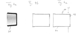
- the forging blank 35 already has a cup-shaped basic shape. Therefore, deep drawing, as is necessary for the sheet metal blank 30, can be dispensed with and the workpiece can only be formed using pressure rollers, as in Fig. 4b represented, transformed. This balances the workpiece Fig. 3c . How further processing is therefore analogous to that in relation to Figures 3c and 3d processing described.
- a stator housing can be manufactured in a simple and efficient manner.
Landscapes
- Engineering & Computer Science (AREA)
- Power Engineering (AREA)
- Manufacturing & Machinery (AREA)
- Manufacture Of Motors, Generators (AREA)
Description
- Die Erfindung betrifft ein Verfahren zum Herstellen eines Statorgehäuses für einen Elektromotor, wobei das Statorgehäuse ein trommelförmiges Umfangsgehäuse und einen Radialring aufweist, welcher mit dem Umfangsgehäuse lösbar verbunden ist.
- Ferner betrifft die Erfindung ein Statorgehäuse für einen Elektromotor mit einem trommelförmigen Umfangsgehäuse und einem Radialring.
- Elektromotoren weisen einen Stator sowie einen sich in Bezug auf den Stator drehenden Rotor auf. Der Stator selbst wird oft in einem Statorgehäuse aufgenommen, das den Stator schützt und meist das Gehäuse für den gesamten Elektromotor ausbildet. Hierbei ist es wünschenswert, ein möglichst effizientes Verfahren zur Herstellung eines Statorgehäuses zu ermöglichen. Zu berücksichtigen ist jedoch, dass teilweise der Stator in das Statorgehäuse eingebaut werden muss und anschließend dieses wiederum verschlossen werden muss. Insofern ist eine zweiteilige Konstruktion notwendig, die meist ein Umfangsgehäuse sowie einen entsprechenden Abschluss aufweist.
- Das Dokument
DE 19 58 771 A1 offenbart ein Verfahren zum Herstellen von Metallteilen durch Tiefziehen. - Der Erfindung liegt die Aufgabe zugrunde, ein Verfahren zum Herstellen eines Statorgehäuses für einen Elektromotor sowie ein Statorgehäuse für einen Elektromotor anzugeben, welche effizient realisiert werden können.
- Diese Aufgabe wird gemäß der Erfindung durch ein Verfahren zum Herstellen eines Statorgehäuses für einen Elektromotor mit den Merkmalen des Anspruchs 1 gelöst. Außerdem wird die Aufgabe durch ein Statorgehäuse für einen Elektromotor mit den Merkmalen des Anspruchs 10 gelöst.
- Weiter vorteilhafte Ausführungsformen der Erfindung sind in den abhängigen Ansprüchen, der Beschreibung sowie in der Erläuterung der Figuren angegeben.
- Entsprechend der Erfindung ist vorgesehen, dass das Statorgehäuse ein trommelförmiges Umgangsgehäuse und einen Radialring aufweist, welcher mit dem Umfangsgehäuse lösbar verbunden ist. Hierzu wird aus einem Ausgangsmaterial durch Umformen ein topfförmiges Werkstück mit einem Umfangswandabschnitt und einem Bodenabschnitt hergestellt. Es kann aber auch ein bereits ein topfförmiges Werkstück aus Ausgangsmaterial verwendet werden. Dann ist der Schritt des Umformens fakultativ. Der Bodenabschnitt wird von dem Umfangswandabschnitt getrennt. Aus dem, insbesondere bereist abgetrennten, Umfangswandabschnitt wird das trommelförmige Umfangswandgehäuse durch Umformen und/oder materialabtragendes Bearbeiten ausgebildet. Aus dem, insbesondere bereist abgetrennten, Bodenabschnitt wird durch Umformen und/oder materialabtragendes Bearbeiten der Radialring ausgebildet.
- Grundsätzlich kann das Abrennen des Radialring vom topfförmigen Werkstück und so das Ausbilden des trommelförmige Umfangswandgehäuse vor oder nach der finalen Bearbeitung des Radialring und des trommelförmige Umfangswandgehäuse, beispielsweise mittels Umformens und/oder materialabtragendes Bearbeiten, erfolgen.
- Entsprechend der Erfindung wurde erkannt, dass es nicht notwendig ist, für ein Statorgehäuse mit einem trommelförmigen Umfangsgehäuse und einem Radialring zwei separate Bauteile aus separaten Rohlingen zu fertigen. Nach der Erfindung ist vorgesehen, aus einem Rohling, der das Ausgangsmaterial liefert, durch Umformen zuerst ein topfförmiges Werkstück zu bilden. Anschließend wird aus diesem Werkstück der Bodenabschnitt abgetrennt. Durch die folgende Bearbeitung wird aus dem Bodenabschnitt der Radialring ausgebildet, wohingegen aus dem Umfangswandabschnitt das trommelförmige Umfangsgehäuse erzeugt werden kann. Es jedoch auch möglich das topfförmige Werkstück weiter umzuformen und erst späterden Radialring abzutrennen und somit auch das trommelförmigen Umfangsgehäuse auszubilden.
- So kann das sonst im Rahmen der Herstellung des trommelförmigen Umfangsgehäuses überflüssiges Material, das als Schrott bezeichnet wird, verwendet werden. Dies bedeutet eine deutliche Materialeinsparung.
- Bevorzugt ist es, wenn an einer axialen Stirnseite des trommelförmigen Umfangsgehäuses ein erstes Klauenprofil und an einer axialen Stirnseite des Radialrings ein zweites Klauenprofil ausgebildet wird. Dies kann beispielsweise durch Materialabtrag erfolgen. Das erste Klauenprofil und das zweite Klauenprofil sind zum Bilden einer Verbindung axial passend ineinandergreifend ausgeformt. Die beiden komplementären Klauenprofile ermöglichen so ein einfaches und dennoch sicheres Verbinden des trommelförmigen Umfangsgehäuses mit dem Radialring. Anders ausgedrückt, kann der Radialring so auf das trommelförmige Umfangsgehäuse aufgesetzt werden. Durch das Klauenprofil wird erreicht, dass hierbei ein sicherer Sitz vorhanden ist.
- Grundsätzlich kann ein beliebiges Ausgangsmaterial verwendet werden. Vorteilhaft ist es jedoch, wenn als Ausgangsmaterial eine Blechronde verwendet wird, welche aus einem Blech ausgestanzt ist. Die Blechronde kann mit einem Mittelloch versehen sein.
- Eine Blechronde, insbesondere mit einem Mittelloch, eignet sich entsprechend der Erfindung dazu, um durch Umformen das topfförmige Werkstück zu erzeugen.
- Alternativ hierzu kann das Ausgangswerkstück auch ein Rohrstück oder ein Schmiederohling, insbesondere mit einer topfförmigen Grundform, sein, welches zu dem topfförmigen Werkstück umgeformt wird.
- Grundsätzlich können verschiedene Verfahren zum Umformen verwendet werden. Bevorzugt ist es im Rahmen der Erfindung ein Tiefziehen, ein Absteckziehen, ein Drücken und/oder Drückwalzen beziehungsweise Kombinationen hiervon zu Umformen vorzusehen. Diese Verfahren bieten einen guten und effizienten Arbeitsablauf. Außerdem sind sie relativ effizient mit entsprechenden Werkmaschinen zu realisieren und erhöhen oft die Festigkeit des Materials. Bei dem Verwenden einer Blechronde kann zuerst ein Tiefziehen und dann ein Drückwalzen angewendet werden. Wird ein Schmiederohling mit einer topfförmigen Grundform verwendet, kann das Tiefziehen entfallen.
- Generell kann ein beliebiges materialabtragendes Bearbeiten durchgeführt werden. Bevorzugt ist es jedoch, wenn ein Stanzen, ein Bohren, ein Fräsen, ein Drehen und/oder ein Laserschneiden angewandt wird. Selbiges gilt auch für Kombinationen hiervon. Diese Verfahren bieten sich insbesondere an, da sie relativ genau durchgeführt werden können.
- Vorteilhafterweise wird der Radialring mit einem Axialabschnitt, der in axialer Richtung ausgerichtet ist, und mit einem Radialabschnitt ausgebildet, welcher in Radialrichtung nach innen ausgerichtet ist. Eine derartige Konstruktion ermöglicht es, an dem Radialabschnitt zusätzliche Befestigungsmöglichkeiten für den Stator oder weitere Bauteile vorzusehen. Diesbezüglich können an dem Radialabschnitt Haltelaschen, insbesondere durch Ausklinken ausgebildet werden, welche beispielsweise mit Befestigungslöchern versehen sind. Es ist aber alternativ oder zusätzlich auch möglich Befestigungslöchern direkt in dem Radialabschnitt vorzusehen und diesen entsprechend auszubilden.
- Ferner betrifft die Erfindung ein Statorgehäuse für einen Elektromotor mit einem trommelförmigen Umfangsgehäuse und einem Radialring, welche axial zusammengesetzt und miteinander verbunden sind sowie aus einem topfförmigen Werkzeug durch Abtrennen gebildet sind. Dies geschieht insbesondere nach dem zuvor beschriebenen erfindungsgemäßen Verfahren.
- Vorteilhaft ist es, wenn an einer axialen Stirnseite des trommelförmigen Umfangsgehäuses ein erstes Klauenprofil und an einer axialen Stirnseite des Radialrings ein zweites Klauenprofil ausgebildet sind, wobei das erste Klauenprofil und das zweite Klauenprofil zum Bilden einer Verbindung axial passend ineinandergreifen. Mittels des Vorsehens von korrespondierenden Klauenprofilen ist es möglich, das trommelförmige Umfangsgehäuse mit dem Radialring sicher zu verbinden. Anders ausgedrückt kann dieser auf das Umfangsgehäuse gesetzt werden. Mittels der Klauenverzahnung wird sichergestellt, dass zum einen die Position festgelegt ist und zum anderen kein Verdrehen auftritt.
- Vorteilhafterweise weist ein radial gerichteter Radialabschnitt des Radialrings Haltelaschen auf, welche insbesondere mit Befestigungslöchern versehen sind. Mittels dieser Befestigungslöcher ist es möglich, wenn der Radialring auf das Umfangsgehäuse gesetzt wird, Teile des Stators oder andere Bauteile zu befestigen.
- Die Erfindung wird nachfolgend anhand eines Ausführungsbeispiels und schematischen Zeichnungen näher erläutert. In diesen Zeichnungen zeigen:
- Fig. 1
- ein erfindungsgemäßes Umfangsgehäuse,
- Fig. 2
- einen erfindungsgemäßen Radialring;
- Figuren 3a bis 3d
- einzelne Schritte beim Herstellen des erfindungsgemäßen Statorgehäuses aus einer Blechronde; und
- Figuren 4a bis 4c
- einzelne Schritte beim Herstellen des erfindungsgemäßen Statorgehäuses aus einem Schmiederohling.
- In
Fig. 1 ist ein erfindungsgemäßes Umfangsgehäuse 10 und inFig. 2 ein erfindungsgemäßer Radialring 20 dargestellt. Diese können zusammengesetzt werden und bilden dann ein Statorgehäuse für einen Elektromotor. - Das Umfangsgehäuse 10 weist eine trommelartige Form auf. An einem Ende ist eine Klauenverzahnung 12 vorgesehen. Die Klauen können im Wesentlichen gleich verteilt an einem Endbereich des Umfangsgehäuses 10 ausgebildet sein. Es sind aber auch unterschiedlich breite Einschnitte möglich. Dies ist nicht zwingend erforderlich, ermöglicht aber ein gezieltes zusammensetzen.
- In
Fig. 2 ist der erfindungsgemäße Radialring 20 gezeigt, der ein zweites Klauenprofil 22 an einem Axialabschnitt 24 aufweist. Dieses ist korrespondierend zu dem ersten Klauenprofil 12 ausgebildet. Dies bedeutet, dass der Radialring 20 auf das Umfangsgehäuse 10 aufgesetzt werden kann. Hierbei greifen die beiden Klauenprofile 12 und 22 ineinander ein, so dass ein sicherer Sitz vorhanden ist. - Der Radialring 20 weist ferner einen Radialabschnitt 26 auf. An diesem sind Befestigungslöcher 28 vorgesehen. Grundsätzlich sind jedoch auch Konstruktionen mit zusätzlichen Haltelaschen 27 oder mit anderen Befestigungsmöglichkeiten als die Befestigungslöcher 28 möglich. Im zusammengesetzten Zustand des Statorgehäuses kann mit den Befestigungslöchern 28 das Statorgehäuse an einem weiteren Bauteil befestigt werden. In ähnlicher Weise kann auch der Stator innerhalb des Gehäuses zusätzlich an dem Radialring angebracht werden.
- Im Folgenden wird unter Bezugnahme auf die
Figuren 3a bis 3d das erfindungsgemäße Herstellungsverfahren des erfindungsgemäßen Statorgehäuses mit dem Umfangsgehäuse 10 und dem Radialring 20 aus einer Blechronde 30 näher erläutert. Hierbei ist das Werkstück jeweils im Querschnitt dargestellt. - In
Fig. 3a ist die Blechronde 30 gezeigt, welche ein Mitteilloch 31 aufweist. Diese kann beispielsweise aus einem Blech ausgestanzt oder in anderer Weise aus diesem ausgeformt werden. Anschließend wird beispielweise mittels Tiefziehens ein Topf 40 ausgeformt. Alternativ zum Verwenden einer Blechronde 30 kann auch ein Rohrstück verwendet werden, welches durch entsprechendes Umformen in die Form des Topfes 40 umgeformt wird. - In einem weiteren Schritt, dessen Endergebnis in
Fig. 3c dargestellt ist, wird die exakte Form mittels Drückwalzen erzeugt. Hierbei kann bereits das Statorgehäuse vorliegen, welches das Umfangsgehäuse 10 und den Radialring 20 aufweist. Beim Drückwalzen kommt es zu einem Kaltverformen und zu einer Materialverfestigung. Auch wird hierbei die Wandstärke verringert. - In
Fig. 3d ist das Werkstück noch im einstückigen Zustand gezeigt. Aufgrund der Montage des Stators ist es jedoch bevorzugt, das Statorgehäuse zweiteilig auszubilden. Aus diesem Grund wird, wie inFig. 3d verdeutlich und durch die Pfeile 45 angedeutet, das topfförmiges Werkstück 50 an den Pfeilen zweigeteilt. So entsteht ein Umfangswandabschnitt 51 sowie ein Bodenabschnitt 52. Die beiden Abschnitte entsprechen nach einer fakultativen Nachbearbeitung, beispielsweise durch Fräsen oder Glätten, dem Umfangsgehäuse 10 sowie dem Radialring 20. - In den
Figuren 4a bis 4c ist das erfindungsgemäße Herstellungsverfahren des erfindungsgemäßen Statorgehäuses mit dem Umfangsgehäuse 10 und dem Radialring 20 aus einem Schmiederohling 35 näher erläutert. Hierbei ist das Werkstück wie zuvor jeweils im Querschnitt dargestellt. - Der Schmiederohling 35 hat bereits eine topfförmige Grundform. Daher kann auf ein Tiefziehen, wie bei der Blechronde 30 notwendig, verzichtet werden und lediglich mittels Drückwalzen das Werkstück, wie in
Fig. 4b dargestellt, umgeformt werden. Dieses gleicht dem Werkstück ausFig. 3c . Wie weitere Bearbeitung ist daher analog zu der in Bezug auf dieFiguren 3c und 3d beschriebenen Bearbeitung. - Mittels des erfindungsgemäßen Herstellungsverfahrens kann in einfacher und effizienter Weise ein Statorgehäuse gefertigt werden.
Claims (13)
- Verfahren zum Herstellen eines Statorgehäuses für einen Elektromotor, wobei das Statorgehäuse ein trommelförmiges Umfangsgehäuse (10) und einen Radialring (20) aufweist, welcher mit dem Umfangsgehäuse (10) lösbar verbunden ist, wobeiaus einem Ausgangsmaterial durch fakultatives Umformen ein topfförmiges Werkstück (50) mit einem Umfangswandabschnitt (51) und einem Bodenabschnitt (52) hergestellt wird,der Bodenabschnitt (52) von dem Umfangswandabschnitt (51) abgetrennt wird,aus dem Umfangswandabschnitt (51) das trommelförmige Umfangsgehäuse (10) durch Umformen und/oder materialabtragendes Bearbeiten gebildet wird undaus dem Bodenabschnitt (52) durch Umformen und/oder materialabtragendes Bearbeiten der Radialring (20) gebildet wird.
- Verfahren nach Anspruch 1,
dadurch gekennzeichnet,
dass an einer axialen Stirnseite des trommelförmigen Umfangsgehäuses (10) ein erstes Klauenprofil (12) und an einer axialen Stirnseite des Radialrings ein zweites Klauenprofil (22), insbesondere durch Materialabtrag, ausgebildet werden, wobei das erste Klauenprofil und das zweite Klauenprofil (22) zum Bilden einer Verbindung axial passend ineinandergreifen. - Verfahren nach Anspruch 1 oder 2,
dadurch gekennzeichnet,
dass das Ausgangsmaterial eine Blechronde (30) ist, welche aus einem Blech ausgestanzt wird. - Verfahren nach Anspruch 3,
dadurch gekennzeichnet,
dass die Blechronde (309 mit einem Mittenloch (31) versehen wird. - Verfahren nach Anspruch 1 oder 2,
dadurch gekennzeichnet,,
dass das Ausgangswerkstück ein Rohrstück ist, welches zu dem topfförmigen Werkstück umgeformt wird. - Verfahren nach Anspruch 1 oder 2,
dadurch gekennzeichnet,,
dass das Ausgangswerkstück ein Schmiederohling, insbesondere mit einer topfförmigen Grundform ist. - Verfahren nach einem der Ansprüche 1 bis 6,
dadurch gekennzeichnet,
dass das Umformen ein Tiefziehen, Abstreckziehen, Drücken und/oder Drückwalzen umfasst. - Verfahren nach einem der Ansprüche 1 bis 7,
dadurch gekennzeichnet,
dass ein materialabtragendes Bearbeiten ein Stanzen, Bohren, Fräsen, Drehen und/oder Laserschneiden umfasst. - Verfahren nach einem der Ansprüche 1 bis 8,
dadurch gekennzeichnet,
dass der Radialring (20) mit einem Axialabschnitt (24), der in axialer Richtung gerichtet ist, und einem Radialabschnitt (26) gebildet wird, welcher in radialer Richtung nach innen gerichtet ist. - Verfahren nach Anspruch 9,
dadurch gekennzeichnet,dass an dem Radialabschnitt (26) Haltelaschen, insbesondere durch Ausklinken, ausgebildet werden, und/oderdass der Radialabschnitt (26) und/oder die Haltelaschen mit Befestigungslöchern (28) versehen werden. - Statorgehäuse für einen Elektromotor mit einem trommelförmigen Umfangsgehäuse (10) und einem Radialring (20), welche axial zusammengesetzt und miteinander verbunden sind sowie aus einem topfförmigen Werkstück (50) durch Abtrennen gebildet sind, nach einem Verfahren nach einem der Ansprüche 1 bis 10.
- Statorgehäuse nach Anspruch 11,
dadurch gekennzeichnet,
dass an einer axialen Stirnseite des trommelförmigen Umfangsgehäuses (10) ein erstes Klauenprofil (12) und an einer axialen Stirnseite des Radialrings ein zweites Klauenprofil (22) ausgebildet sind, wobei das erste Klauenprofil (12) und das zweite Klauenprofil (22) zum Bilden einer Verbindung axial passend ineinandergreifen. - Statorgehäuse nach Anspruch 11 oder 12,
dadurch gekennzeichnet,
dass ein radial gerichteter Radialabschnitt (26) des Radialrings Haltelaschen (27) umfasst, welche insbesondere mit Befestigungslöchern (28) versehen sind.
Priority Applications (2)
| Application Number | Priority Date | Filing Date | Title |
|---|---|---|---|
| EP22157518.6A EP4231509B1 (de) | 2022-02-18 | 2022-02-18 | Statorgehäuse |
| ES22157518T ES2982335T3 (es) | 2022-02-18 | 2022-02-18 | Carcasa de estator |
Applications Claiming Priority (1)
| Application Number | Priority Date | Filing Date | Title |
|---|---|---|---|
| EP22157518.6A EP4231509B1 (de) | 2022-02-18 | 2022-02-18 | Statorgehäuse |
Publications (3)
| Publication Number | Publication Date |
|---|---|
| EP4231509A1 EP4231509A1 (de) | 2023-08-23 |
| EP4231509B1 true EP4231509B1 (de) | 2024-03-27 |
| EP4231509C0 EP4231509C0 (de) | 2024-03-27 |
Family
ID=80953311
Family Applications (1)
| Application Number | Title | Priority Date | Filing Date |
|---|---|---|---|
| EP22157518.6A Active EP4231509B1 (de) | 2022-02-18 | 2022-02-18 | Statorgehäuse |
Country Status (2)
| Country | Link |
|---|---|
| EP (1) | EP4231509B1 (de) |
| ES (1) | ES2982335T3 (de) |
Family Cites Families (2)
| Publication number | Priority date | Publication date | Assignee | Title |
|---|---|---|---|---|
| GB1225930A (de) * | 1968-12-20 | 1971-03-24 | ||
| DE102009056142A1 (de) * | 2009-11-27 | 2011-06-01 | Schaeffler Technologies Gmbh & Co. Kg | Spanlos hergestellte Lagerschale |
-
2022
- 2022-02-18 ES ES22157518T patent/ES2982335T3/es active Active
- 2022-02-18 EP EP22157518.6A patent/EP4231509B1/de active Active
Also Published As
| Publication number | Publication date |
|---|---|
| ES2982335T3 (es) | 2024-10-15 |
| EP4231509A1 (de) | 2023-08-23 |
| EP4231509C0 (de) | 2024-03-27 |
Similar Documents
| Publication | Publication Date | Title |
|---|---|---|
| EP2214862B1 (de) | Welle-nabe-bauteil sowie verfahren zur herstellung eines derartigen bauteils | |
| EP3409392B1 (de) | Verfahren zur herstellung von stanzteilen | |
| DE3419868A1 (de) | Reifenpressform und verfahren zu ihrer herstellung | |
| EP2213396A2 (de) | Verfahren und Vorrichtung zum Herstellen einer Welle | |
| EP2091681B2 (de) | Schneidplatte für ein Drehwerkzeug und Bearbeitungsverfahren mit dieser Schneidplatte | |
| DE102017104159B4 (de) | Zahnrad für eine Ausgleichswelle und eine Ausgleichswelle | |
| DE19616833B4 (de) | Verfahren zur Herstellung einer Keilriemenscheibe | |
| DE102011080738A1 (de) | Verfahren zur Herstellung eines Wälzlagerverbundes | |
| DE102004031830A1 (de) | Verfahren zur Herstellung einer Lageranordnung | |
| EP3379700B1 (de) | Gehäuse und verfahren zum herstellen eines gehäuses | |
| EP1914022B1 (de) | Verfahren und Werkzeug zum Herstellen von durch Umform- und Feinschneidvorgänge erzeugte dreidimensionale Beschläge | |
| DE102007016110A1 (de) | Verfahren und Vorrichtung für ein Trägerkreuz | |
| DE19915027A1 (de) | Getriebeteil und Verfahren zum Formen eines Getriebeteils | |
| EP3316456A1 (de) | Motorwelle eines elektromotors sowie verfahren zu dessen herstellung | |
| DE102012202446A1 (de) | Getrieberad, insbesondere Sonnenrad für ein Differenzialgetriebe | |
| EP1697066B1 (de) | Verfahren zur herstellung eines flansches an einer blechronde | |
| EP4231509A1 (de) | Statorgehäuse | |
| EP3865387A1 (de) | Ritzel für einen fahrrad-antrieb | |
| WO1994020235A1 (de) | Verfahren zur spanlosen herstellung einer nabe eines die nabe aufweisenden getriebeteiles | |
| EP2619885B1 (de) | Verfahren zum herstellen einer gehäuseanordnung, gehäuseanordnung sowie stempelvorrichtung | |
| DE102015219855A1 (de) | Hohlrad mit Innenverzahnung und Kronenverzahnung, sowie Verfahren zu dessen Herstellung und Schaltgetriebe mit solchem Hohlrad | |
| EP3986633B1 (de) | Bodenteil zur herstellung einer patronenhülse sowie patronenhülse, verfahren zur herstellung eines bodenteils für eine patronenhülse sowie verfahren zur herstellung einer patronenhülse | |
| DE10344885B3 (de) | Verfahren zum Herstellen eines Werkstücks mit Nabe mittels einer Presse und Blechwerkstück | |
| DE102009040510A1 (de) | Rotor für eine Pumpe | |
| EP2339212A1 (de) | Riemenscheibe und Verfahren zu ihrer Herstellung |
Legal Events
| Date | Code | Title | Description |
|---|---|---|---|
| PUAI | Public reference made under article 153(3) epc to a published international application that has entered the european phase |
Free format text: ORIGINAL CODE: 0009012 |
|
| STAA | Information on the status of an ep patent application or granted ep patent |
Free format text: STATUS: REQUEST FOR EXAMINATION WAS MADE |
|
| 17P | Request for examination filed |
Effective date: 20221111 |
|
| AK | Designated contracting states |
Kind code of ref document: A1 Designated state(s): AL AT BE BG CH CY CZ DE DK EE ES FI FR GB GR HR HU IE IS IT LI LT LU LV MC MK MT NL NO PL PT RO RS SE SI SK SM TR |
|
| GRAP | Despatch of communication of intention to grant a patent |
Free format text: ORIGINAL CODE: EPIDOSNIGR1 |
|
| STAA | Information on the status of an ep patent application or granted ep patent |
Free format text: STATUS: GRANT OF PATENT IS INTENDED |
|
| INTG | Intention to grant announced |
Effective date: 20231113 |
|
| RIN1 | Information on inventor provided before grant (corrected) |
Inventor name: BEHRENDT, CARSTEN Inventor name: DRIXELIUS, GEORG Inventor name: SCHROEDER, DANIEL |
|
| GRAS | Grant fee paid |
Free format text: ORIGINAL CODE: EPIDOSNIGR3 |
|
| GRAA | (expected) grant |
Free format text: ORIGINAL CODE: 0009210 |
|
| STAA | Information on the status of an ep patent application or granted ep patent |
Free format text: STATUS: THE PATENT HAS BEEN GRANTED |
|
| AK | Designated contracting states |
Kind code of ref document: B1 Designated state(s): AL AT BE BG CH CY CZ DE DK EE ES FI FR GB GR HR HU IE IS IT LI LT LU LV MC MK MT NL NO PL PT RO RS SE SI SK SM TR |
|
| REG | Reference to a national code |
Ref country code: GB Ref legal event code: FG4D Free format text: NOT ENGLISH |
|
| REG | Reference to a national code |
Ref country code: CH Ref legal event code: EP |
|
| REG | Reference to a national code |
Ref country code: DE Ref legal event code: R096 Ref document number: 502022000647 Country of ref document: DE |
|
| REG | Reference to a national code |
Ref country code: IE Ref legal event code: FG4D Free format text: LANGUAGE OF EP DOCUMENT: GERMAN |
|
| U01 | Request for unitary effect filed |
Effective date: 20240408 |
|
| U07 | Unitary effect registered |
Designated state(s): AT BE BG DE DK EE FI FR IT LT LU LV MT NL PT SE SI Effective date: 20240417 |
|
| PG25 | Lapsed in a contracting state [announced via postgrant information from national office to epo] |
Ref country code: GR Free format text: LAPSE BECAUSE OF FAILURE TO SUBMIT A TRANSLATION OF THE DESCRIPTION OR TO PAY THE FEE WITHIN THE PRESCRIBED TIME-LIMIT Effective date: 20240628 |
|
| PG25 | Lapsed in a contracting state [announced via postgrant information from national office to epo] |
Ref country code: HR Free format text: LAPSE BECAUSE OF FAILURE TO SUBMIT A TRANSLATION OF THE DESCRIPTION OR TO PAY THE FEE WITHIN THE PRESCRIBED TIME-LIMIT Effective date: 20240327 Ref country code: RS Free format text: LAPSE BECAUSE OF FAILURE TO SUBMIT A TRANSLATION OF THE DESCRIPTION OR TO PAY THE FEE WITHIN THE PRESCRIBED TIME-LIMIT Effective date: 20240627 |
|
| PG25 | Lapsed in a contracting state [announced via postgrant information from national office to epo] |
Ref country code: RS Free format text: LAPSE BECAUSE OF FAILURE TO SUBMIT A TRANSLATION OF THE DESCRIPTION OR TO PAY THE FEE WITHIN THE PRESCRIBED TIME-LIMIT Effective date: 20240627 Ref country code: NO Free format text: LAPSE BECAUSE OF FAILURE TO SUBMIT A TRANSLATION OF THE DESCRIPTION OR TO PAY THE FEE WITHIN THE PRESCRIBED TIME-LIMIT Effective date: 20240627 Ref country code: HR Free format text: LAPSE BECAUSE OF FAILURE TO SUBMIT A TRANSLATION OF THE DESCRIPTION OR TO PAY THE FEE WITHIN THE PRESCRIBED TIME-LIMIT Effective date: 20240327 Ref country code: GR Free format text: LAPSE BECAUSE OF FAILURE TO SUBMIT A TRANSLATION OF THE DESCRIPTION OR TO PAY THE FEE WITHIN THE PRESCRIBED TIME-LIMIT Effective date: 20240628 |
|
| PG25 | Lapsed in a contracting state [announced via postgrant information from national office to epo] |
Ref country code: IS Free format text: LAPSE BECAUSE OF FAILURE TO SUBMIT A TRANSLATION OF THE DESCRIPTION OR TO PAY THE FEE WITHIN THE PRESCRIBED TIME-LIMIT Effective date: 20240727 |
|
| PG25 | Lapsed in a contracting state [announced via postgrant information from national office to epo] |
Ref country code: SM Free format text: LAPSE BECAUSE OF FAILURE TO SUBMIT A TRANSLATION OF THE DESCRIPTION OR TO PAY THE FEE WITHIN THE PRESCRIBED TIME-LIMIT Effective date: 20240327 |
|
| REG | Reference to a national code |
Ref country code: ES Ref legal event code: FG2A Ref document number: 2982335 Country of ref document: ES Kind code of ref document: T3 Effective date: 20241015 |
|
| PG25 | Lapsed in a contracting state [announced via postgrant information from national office to epo] |
Ref country code: CZ Free format text: LAPSE BECAUSE OF FAILURE TO SUBMIT A TRANSLATION OF THE DESCRIPTION OR TO PAY THE FEE WITHIN THE PRESCRIBED TIME-LIMIT Effective date: 20240327 |
|
| PG25 | Lapsed in a contracting state [announced via postgrant information from national office to epo] |
Ref country code: PL Free format text: LAPSE BECAUSE OF FAILURE TO SUBMIT A TRANSLATION OF THE DESCRIPTION OR TO PAY THE FEE WITHIN THE PRESCRIBED TIME-LIMIT Effective date: 20240327 |
|
| PG25 | Lapsed in a contracting state [announced via postgrant information from national office to epo] |
Ref country code: SK Free format text: LAPSE BECAUSE OF FAILURE TO SUBMIT A TRANSLATION OF THE DESCRIPTION OR TO PAY THE FEE WITHIN THE PRESCRIBED TIME-LIMIT Effective date: 20240327 |
|
| PG25 | Lapsed in a contracting state [announced via postgrant information from national office to epo] |
Ref country code: SM Free format text: LAPSE BECAUSE OF FAILURE TO SUBMIT A TRANSLATION OF THE DESCRIPTION OR TO PAY THE FEE WITHIN THE PRESCRIBED TIME-LIMIT Effective date: 20240327 Ref country code: SK Free format text: LAPSE BECAUSE OF FAILURE TO SUBMIT A TRANSLATION OF THE DESCRIPTION OR TO PAY THE FEE WITHIN THE PRESCRIBED TIME-LIMIT Effective date: 20240327 Ref country code: RO Free format text: LAPSE BECAUSE OF FAILURE TO SUBMIT A TRANSLATION OF THE DESCRIPTION OR TO PAY THE FEE WITHIN THE PRESCRIBED TIME-LIMIT Effective date: 20240327 Ref country code: PL Free format text: LAPSE BECAUSE OF FAILURE TO SUBMIT A TRANSLATION OF THE DESCRIPTION OR TO PAY THE FEE WITHIN THE PRESCRIBED TIME-LIMIT Effective date: 20240327 Ref country code: IS Free format text: LAPSE BECAUSE OF FAILURE TO SUBMIT A TRANSLATION OF THE DESCRIPTION OR TO PAY THE FEE WITHIN THE PRESCRIBED TIME-LIMIT Effective date: 20240727 Ref country code: CZ Free format text: LAPSE BECAUSE OF FAILURE TO SUBMIT A TRANSLATION OF THE DESCRIPTION OR TO PAY THE FEE WITHIN THE PRESCRIBED TIME-LIMIT Effective date: 20240327 |
|
| REG | Reference to a national code |
Ref country code: DE Ref legal event code: R097 Ref document number: 502022000647 Country of ref document: DE |
|
| PLBE | No opposition filed within time limit |
Free format text: ORIGINAL CODE: 0009261 |
|
| STAA | Information on the status of an ep patent application or granted ep patent |
Free format text: STATUS: NO OPPOSITION FILED WITHIN TIME LIMIT |
|
| 26N | No opposition filed |
Effective date: 20250103 |
|
| PG25 | Lapsed in a contracting state [announced via postgrant information from national office to epo] |
Ref country code: MC Free format text: LAPSE BECAUSE OF FAILURE TO SUBMIT A TRANSLATION OF THE DESCRIPTION OR TO PAY THE FEE WITHIN THE PRESCRIBED TIME-LIMIT Effective date: 20240327 |
|
| REG | Reference to a national code |
Ref country code: CH Ref legal event code: PL |
|
| U90 | Renewal fees not paid: noting of loss of rights |
Free format text: RENEWAL FEE NOT PAID FOR YEAR 04 Effective date: 20250918 |
|
| PG25 | Lapsed in a contracting state [announced via postgrant information from national office to epo] |
Ref country code: CH Free format text: LAPSE BECAUSE OF NON-PAYMENT OF DUE FEES Effective date: 20250228 |
|
| U93 | Unitary patent lapsed |
Free format text: RENEWAL FEE NOT PAID Effective date: 20250228 |
|
| PG25 | Lapsed in a contracting state [announced via postgrant information from national office to epo] |
Ref country code: IE Free format text: LAPSE BECAUSE OF NON-PAYMENT OF DUE FEES Effective date: 20250218 |
|
| REG | Reference to a national code |
Ref country code: ES Ref legal event code: FD2A Effective date: 20260326 |
|
| PG25 | Lapsed in a contracting state [announced via postgrant information from national office to epo] |
Ref country code: ES Free format text: LAPSE BECAUSE OF NON-PAYMENT OF DUE FEES Effective date: 20250219 |