EP4231471B1 - Kabelvorbereitungsmaschine - Google Patents
Kabelvorbereitungsmaschine Download PDFInfo
- Publication number
- EP4231471B1 EP4231471B1 EP23174153.9A EP23174153A EP4231471B1 EP 4231471 B1 EP4231471 B1 EP 4231471B1 EP 23174153 A EP23174153 A EP 23174153A EP 4231471 B1 EP4231471 B1 EP 4231471B1
- Authority
- EP
- European Patent Office
- Prior art keywords
- cable
- braid
- pulley
- arm
- blade
- Prior art date
- Legal status (The legal status is an assumption and is not a legal conclusion. Google has not performed a legal analysis and makes no representation as to the accuracy of the status listed.)
- Active
Links
Images


Classifications
-
- H—ELECTRICITY
- H02—GENERATION; CONVERSION OR DISTRIBUTION OF ELECTRIC POWER
- H02G—INSTALLATION OF ELECTRIC CABLES OR LINES, OR OF COMBINED OPTICAL AND ELECTRIC CABLES OR LINES
- H02G1/00—Methods or apparatus specially adapted for installing, maintaining, repairing or dismantling electric cables or lines
- H02G1/12—Methods or apparatus specially adapted for installing, maintaining, repairing or dismantling electric cables or lines for removing insulation or armouring from cables, e.g. from the end thereof
- H02G1/1202—Methods or apparatus specially adapted for installing, maintaining, repairing or dismantling electric cables or lines for removing insulation or armouring from cables, e.g. from the end thereof by cutting and withdrawing insulation
- H02G1/1248—Machines
- H02G1/1265—Machines the cutting element rotating about the wire or cable
-
- H—ELECTRICITY
- H01—ELECTRIC ELEMENTS
- H01R—ELECTRICALLY-CONDUCTIVE CONNECTIONS; STRUCTURAL ASSOCIATIONS OF A PLURALITY OF MUTUALLY-INSULATED ELECTRICAL CONNECTING ELEMENTS; COUPLING DEVICES; CURRENT COLLECTORS
- H01R43/00—Apparatus or processes specially adapted for manufacturing, assembling, maintaining, or repairing of line connectors or current collectors or for joining electric conductors
- H01R43/28—Apparatus or processes specially adapted for manufacturing, assembling, maintaining, or repairing of line connectors or current collectors or for joining electric conductors for wire processing before connecting to contact members, not provided for in groups H01R43/02 - H01R43/26
-
- H—ELECTRICITY
- H01—ELECTRIC ELEMENTS
- H01R—ELECTRICALLY-CONDUCTIVE CONNECTIONS; STRUCTURAL ASSOCIATIONS OF A PLURALITY OF MUTUALLY-INSULATED ELECTRICAL CONNECTING ELEMENTS; COUPLING DEVICES; CURRENT COLLECTORS
- H01R9/00—Structural associations of a plurality of mutually-insulated electrical connecting elements, e.g. terminal strips or terminal blocks; Terminals or binding posts mounted upon a base or in a case; Bases therefor
- H01R9/03—Connectors arranged to contact a plurality of the conductors of a multiconductor cable, e.g. tapping connections
- H01R9/05—Connectors arranged to contact a plurality of the conductors of a multiconductor cable, e.g. tapping connections for coaxial cables
- H01R9/0518—Connection to outer conductor by crimping or by crimping ferrule
Definitions
- the subject matter herein relates generally to a cable preparation machine.
- Cables are used in many applications.
- an end of the cable is prepared for termination to a terminal, contact, connector, circuit board or other component by exposing the conductor(s) of the cable.
- the cable typically includes a center conductor, an inner insulator, an outer conductor, such as in the form of a cable braid, and an outer insulator, such as a cable jacket.
- Cable preparation processes typically involve removal of the various layers of the cable for termination of the conductive layers to the component. For example, the outer insulator is stripped to expose the cable braid, the cable braid is stripped to expose the inner insulator and the inner insulator is stripped to expose the inner conductor.
- the cable braid is manufactured from a metal, braided material.
- a punch and die machine is used for cutting the cable braid where a die is inserted under the cable braid and a punch is closed around the cable braid and the die to cut the cable braid.
- Such machines are complex and expensive.
- loading of the die between the cable braid and the inner insulator is difficult.
- the cable braid is typically flared outward, such as by hand, to create a space for the die, which is time consuming and may injure the operator.
- the arms are configured to position the braid blades in clearance positions, cutting positions, and pinching positions.
- the braid blades engage the cable braid in the pinching position; in the pinching position the braid blades are moved relative to the cutting positions.
- the braid blades may be moved to the pinching position after the cable braid is cut to hold the removed slugs of the cable braid while the cable is removed from the cable opening to discard the removed slugs from the end of the cable.
- the braid blades may be moved to the pinching position to hold the cable braid as the mandrel is inserted onto the end of the cable. Furthermore the braid blades amy be moved to the pinching position to flare the cable braid outward prior to inserting the mandrel on to the end of the cable
- the arms of the cable preparation machine may be moved between a retracted position and an advanced position by rotating the blade assembly about the cable axis.
- the position of the arms may be electronically controlled to control a depth of cutting of the braid blades on the cable braid.
- the cutting force of the braid blades (212) against the cable braid (156) may be used to control the position of the arms (270).
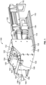
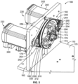
- FIG. 1 illustrates a cable preparation machine 100 in accordance with an exemplary embodiment.
- the cable preparation machine 100 includes a cable cutting device 102 configured to cut and remove one or more insulators from an end 150 of a cable 104, such as an outer insulator 152 (for example, a cable jacket) and/or an inner insulator 154, and configured to cut and remove a cable braid 156 from the end 150 of the cable 104.
- the inner insulator 154 separates the cable braid 156 from an inner conductor 158 of the cable 104.
- the cable braid 156 provides electrical shielding for the inner conductor 158.
- the inner conductor 158 may be a solid core wire or a stranded wire.
- the cable preparation machine 100 is configured to flare the cable braid 156.
- the blade assembly 204 is configured for cutting the cable braid 156 from the end 150 of the cable 104 in a second cutting configuration of the cable cutting device 102 when the cable 104 is positioned in the cable opening 174.
- the drive assembly 202, the pulley assembly 200 and the blade assembly 204 are operated differently in the second cutting configuration than the first cutting configuration.
- the blade assembly 204 may be configured for removing the cable braid slug that is removed from the cable 104, such as by holding the cable braid slug in the cable opening 174 as the cable 104 is drawn forward in the cable opening 174 until the cable braid slug falls off the end of the cable 104.
- the cable 104 may then be repositioned in the cable opening 174, such as for removal of the inner insulator 154 or manipulation of the cable braid 156.
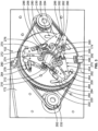
- the rear pulley 222 is rotated at a faster rate than the front pulley 220 to actuate the blade assembly 204.
- the pulley assembly 200 may be used to advance the braid blade 212 from the normal position for closing the braid blade 212 on the cable 104 for cutting/manipulating/flaring the cable braid 156 or may be used to retract (for example, open) the insulation blade 210 from a closed position back to the normal position in the second drive configuration.
- the front pulley 220 and the rear pulley 222 are rotated at the same rate.
- the arm return springs 278 may be coupled to the front pulley 220 rather than between the arms 270 in alternative embodiments.
- the arm actuation pin 262 engages the first sides 282 of the first and second arms 272, 274 proximate to the outer ends 288. Other locations are possible in alternative embodiments.
- the insulation blade 210 is mounted to the first arm 272 proximate to the second side 284 at the inner end 286. The insulation blade 210 extends inward from the inner end 286. When the first arm 272 is pivoted, the cutting edge of the insulation blade 210 is closed inward toward the cable opening 174 to engage and cut the cable 104.
- the braid blade 212 is mounted to the second arm 274 proximate to the second side 284 at the inner end 286.
- the braid blade 212 extends inward from the inner end 286.
- the cutting edge of the braid blade 212 is closed inward toward the cable opening 174 to engage and cut the cable 104.
- the blade assembly 204 may include single arms 270 each holding one of the insulation blades 210 and one of the braid blades 212.
- the first and second arms 272, 274 may be part of a single unitary body having a pocket or opening that receives the arm actuation pin 262.
- the drive assembly 202 includes a position sensor assembly for sensing a rotational position of the pulley assembly 200.
- the position sensor assembly includes a fixed position sensor 290 and a rotating position sensor 292.
- the rotating position sensor 292 is fixed to the front pulley 220 and rotates relative to the fixed position sensor 290 with the front pulley 220.
- the fixed position sensor 290 senses a rotational position of the front pulley 220 based on the location of the rotating position sensor 292.
- the fixed position sensor 290 may be a proximity sensor.
- the rear pulley 222 may additionally or alternatively hold the rotating position sensor 292 to sense a position of the rear pulley 222.
- the braid blades 212 may engage the cable braid 156 along the flared section.
- the braid blades 212 are retracted away from the cable braid 156 to clearance positions ( Figure 9 ) to provide clearance and allow the mandrel 128 to be further advanced onto the end of the cable 104.
- the mandrel 128 may be advanced beyond the base of the flared section to a fully loaded position.
- Figure 10 illustrates the mandrel 128 advanced forward of the braid blades 212 on the end of the cable 104.
- the flared section provides a funneled area of the cable braid 156 that allows the mandrel 128 to be initially loaded into the gap 159. Once the mandrel 128 is loaded forward of the end of the cable braid 156, the mandrel 128 may be pushed onto the end of the cable 104 between the cable braid 156 and the inner insulator 154 to force the cable braid 156 outward for loading the mandrel 128 onto the cable 104.
- the cable cutting device 102 is used to cut the cable braid 156.
- the braid blades 212 are closed around the cable braid 156 to cutting positions ( Figure 12 ).
- the arms 270 are pivoted to the advanced positions to close the braid blades 212 around the cable braid 156.
- the braid blades 212 press against the cable braid 156 such that the cable braid 156 may be cut against the mandrel 128.
- the shear feature 166 cooperates with the braid blades 212 to cut the cable braid 156.
- the arms 270 may be moved between the retracted positions and the advanced positions by rotating the blade assembly 204 about the cable axis 176 onto the cable braid 156.
- the positioning of the arms 270 is electronically controlled to control a depth of cutting of the braid blades 212 on the cable braid 156.
- the drive assembly 202 may be used to electronically control the pulley assembly 200 to control the positions of the arms 270, and thus the depth of cutting of the braid blades 212.
- the positioning of the arms 270 may be controlled based on cutting force of the braid blades 212 against the cable braid 156.
- sensors may be provided within the system to measure the force of the braid blades 212 on the cable braid 156.
- the arms 270 may be advanced until a predetermined force of the braid blades 212 against the cable braid 156 is achieved.
- the blade assembly 204 is configured to cut the cable braids 156 of different diameter cables 104 by controlling the depths of the braid blades 212 at the advanced positions.
- different diameter mandrels correspond to the different diameter cables.
- the mandrel 128 may be replaced with a different diameter mandrel 128 for loading onto the end of the different diameter cable.
- the end 157 of the cable braid 156 forms a removable slug 155 configured to be removed from the end of the cable 104 ( Figure 13 ).
- the cable 104 may be moved forward to separate the slug 155 from the cable braid 156.
- the mandrel 128 may be moved forward with the cable 104 to position the removable slug 155 relative to the mandrel 128.
- the braid blades 212 may be held in pinching positions ( Figure 14 ) on the removable slug 155 to hold the removable slug as the cable 104 is moved forward.
- the removable slug 155 may be pinched against the mandrel 128 as the cable 104 is moved forward.
- the cable 104 is moved forward and the mandrel 128 is moved rearward ( Figure 15 ).
- the braid blades 212 may hold the slug 155 as the cable 104 is moved forward and the mandrel 128 is moved rearward. Once the cable 104 is clear of the slug 155 and the mandrel is clear of the slug 155, the slug 155 may be discarded ( Figure 16 ).
Landscapes
- Engineering & Computer Science (AREA)
- Manufacturing & Machinery (AREA)
- Removal Of Insulation Or Armoring From Wires Or Cables (AREA)
Claims (15)
- Kabelvorbereitungsmaschine (100), die Folgendes umfasst:einen Rahmen (110), der eine Kabelvorbereitungszone (112) bildet, wobei der Rahmen eine Kabelöffnung (126) aufweist, die zum Aufnehmen eines Endes (150) eines Kabels (104) darin entlang einer Kabelachse (176) konfiguriert ist, wobei das Kabel (104) einen Kabelisolator (152, 154) und ein Kabelgeflecht (156) umfasst;eine Antriebsanordnung (202), die in einer ersten Antriebskonfiguration und einer zweiten Antriebskonfiguration betrieben werden kann, undeine Klingenanordnung (204), die mehrere Arme (270) und an den entsprechenden Armen (270) montierte Schneidklingen umfasst, wobei die Klingenanordnung operativ mit der Antriebsanordnung (202) gekoppelt ist, so dass die Klingenanordnung (204) um die Kabelachse (176) gedreht wird; undeinen Dorn (128), der mit dem Ende (150) des Kabels zwischen dem Kabelgeflecht (156) und einem inneren Isolator (154) des Kabels gekoppelt werden kann, um eine harte Oberfläche zum Tragen des Kabelgeflechts während des Schneidvorgangs bereitzustellen, wobei der Dorn (128) operativ mit einem Schlitten (168) gekoppelt ist, der den Dorn (128) relativ zur Kabelöffnung bewegt; der Schlitten (168) den Dorn (128) während des Betriebs entlang der Kabelachse (176) vor und zurück schiebt und der Dorn (128) ein durch eine Außenfläche des Dorns definiertes Schermerkmal (166) aufweist;wobei jeder Arm (270) eine zum Schneiden der Isolierung (152, 154) des Kabels (104) konfigurierte Isolationsklinge (210) und eine zum Schneiden des Geflechts (156) des Kabels (104) konfigurierte Geflechtklinge (212) umfasst, wobei, wenn das Kabel in der Kabelöffnung positioniert ist und die Antriebsanordnung (202) in einer ersten Antriebskonfiguration betrieben wird, die Isolationsklingen (210) betätigt werden, um dadurch die Isolierung (152, 154) vom Kabel (104) abzuschneiden, und wenn die Antriebsanordnung (202) in einer zweiten Antriebskonfiguration betrieben wird, die Geflechtklingen (212) betätigt werden, um dadurch das Geflecht (156) vom Kabel (104) abzuschneiden, wobei die Geflechtklingen (212) Kanten aufweisen, die zum Eingreifen in ein Kabelgeflecht (156) des Kabels konfiguriert sind, um das Kabelgeflecht abzuschneiden, und wobei, wenn die Antriebsanordnung (202) in einer zweiten Antriebskonfiguration betrieben wird, die Kanten (164) der Geflechtklingen (212) zum Schließen in Richtung des Schermerkmals (166) konfiguriert sind, um das Kabelgeflecht (156) zwischen der Geflechtklinge (212) und dem Schermerkmal (166) zu schneiden.
- Kabelvorbereitungsmaschine (100) nach Anspruch 1, wobei das Schermerkmal (166) eine Nut im Dorn (128) ist, wobei die Geflechtklingen (212) um die Nut gedreht werden, um das Kabelgeflecht (156) zu schneiden.
- Kabelvorbereitungsmaschine (100) nach Anspruch 1 oder 2, wobei die Klingenanordnung zum Schneiden des Isolators (152) und des Kabelgeflechts (156) mit unterschiedlichen Schneidklingen (206) der Klingenanordnung konfiguriert ist, ohne das Kabel (104) aus der Kabelvorbereitungszone zu entfernen.
- Kabelvorbereitungsmaschine (100) nach einem der vorherigen Ansprüche, die ferner eine Riemenscheibenanordnung (200) umfasst, die um die Kabelachse (176) drehbar mit dem Rahmen (110) gekoppelt ist, wobei die Riemenscheibenanordnung (200) eine vordere Riemenscheibe (220) und eine hintere Riemenscheibe (222) umfasst, wobei die vordere Riemenscheibe (220) unabhängig von und relativ zu der hinteren Riemenscheibe (222) drehbar ist, wobei die Antriebsanordnung (202) operativ mit der Riemenscheibenanordnung (200) gekoppelt ist, um die Riemenscheibenanordnung (200) um die Kabelachse (176) zu drehen.
- Kabelvorbereitungsmaschine (100) nach Anspruch 4, wobei die ein oder mehreren Arme (270) über einen Armdrehzapfen (276) schwenkbar mit der vorderen Riemenscheibe (220) gekoppelt sind, wobei, wenn das Kabel in der Kabelöffnung (126) positioniert ist und die vordere Riemenscheibe (220) in eine erste Richtung gedreht wird, die Isolationsklinge betätigt wird, um dadurch die Isolierung (152, 154) vom Kabel (104) abzuschneiden, und wenn die vordere Riemenscheibe (220) in eine zweite, entgegengesetzte Richtung gedreht wird, die Geflechtklinge (212) betätigt wird, um dadurch das Geflecht (156) vom Kabel (104) abzuschneiden.
- Kabelvorbereitungsmaschine (100) nach Anspruch 4 oder 5, wobei die vordere Riemenscheibe (220) Schlitze (264) aufweist und die hintere Riemenscheibe (222) einen Armbetätigungsstift (262) aufweist, der sich von der hinteren Riemenscheibe (222) in einen Schlitz (264) in der vorderen Riemenscheibe (220) erstreckt, wobei der Armbetätigungsstift (262) zum Eingreifen in die Klingenanordnung konfiguriert ist, wobei, wenn sich die vordere Riemenscheibe (220) relativ zur hinteren Riemenscheibe (222) dreht, der Armbetätigungsstift (262) mit der Klingenanordnung (204) in Eingriff kommt, um die Klingenanordnung (204) zu betätigen.
- Kabelvorbereitungsmaschine (100) nach Anspruch 6, wobei jeder Arm (270) als ein Satz ausgelegt ist, wobei jeder Satz einen ersten Arm (272) und einen zweiten Arm (274) umfasst, wobei sowohl der erste (272) als auch der zweite (274) Arm eine erste Seite (282) aufweisen, wobei der erste Arm (272) zum Halten einer Isolationsklinge (210) zum Schneiden der Isolatoren (152, 154) und der zweite Arm (274) zum Halten der Geflechtklinge (212) zum Schneiden des Kabelgeflechts (156) konfiguriert ist, wobei der Betätigungsstift (262) zum Eingreifen in die erste Seite (282) des ersten (272) und des zweiten (274) Arms konfiguriert ist.
- Kabelvorbereitungsmaschine (100) nach Anspruch 7, wobei jeder Arm (272, 274) einen Körper 280 aufweist, der sich zwischen einer ersten Seite (282) und einer zweiten Seite (284) erstreckt.
- Kabelvorbereitungsmaschine (100) nach Anspruch 7 oder 8, wobei jeder Arm (272, 274) ein inneres Ende (286) und ein äußeres Ende (288) aufweist und der Armdrehzapfen (276) sich in der Nähe der ersten Seite des inneren Endes (286) des Körpers (280) befindet.
- Kabelvorbereitungsmaschine (100) nach einem der Ansprüche 6 bis 9, wobei der Armdrehzapfen (276) gegenüber dem Armantriebszapfen (262) versetzt ist, so dass, wenn der Armantriebszapfen (262) in den Arm (270) eingreift und ihn antreibt, der Arm (270) um den Armdrehzapfen (276) geschwenkt wird, um die Schneidklinge (206) zum Schneiden des Kabels (104) zu schließen.
- Kabelvorbereitungsmaschine (100) nach einem der Ansprüche 7 bis 10, die ferner einen Anschlagstift (266) umfasst, wobei der Anschlagstift (266) zum Anliegen an den ersten Seiten (282) des ersten (272) und zweiten (274) Arms konfiguriert ist.
- Kabelvorbereitungsmaschine (100) nach einem der Ansprüche 4 bis 11, wobei die Isolationsklinge (210) und die Geflechtklinge (212) mit der Riemenscheibenanordnung (200) um dieselbe Kabelachse (176) drehbar sind.
- Kabelvorbereitungsmaschine (100) nach einem der Ansprüche 4 bis 12, wobei die Arme (270) relativ zur vorderen Riemenscheibe (200) schwenkbar sind, um die Schnitttiefe einer Klinge (206) zu verändern.
- Kabelvorbereitungsmaschine (100) nach einem der Ansprüche 4 bis 13, wobei die vordere Riemenscheibe (220) schneller gedreht wird als die hintere Riemenscheibe (222), um die Klingenanordnung (204) in eine erste Schneidkonfiguration zu bringen, und die hintere Riemenscheibe schneller gedreht wird als die vordere Riemenscheibe, um die Klingenanordnung in eine zweite Schneidkonfiguration zu bringen.
- Kabelvorbereitungsmaschine (100) nach einem der Ansprüche 4 bis 14, wobei die Antriebsanordnung (202) eine erste Antriebseinheit (230) umfasst, die operativ mit der vorderen Riemenscheibe (220) gekoppelt ist, um die vordere Riemenscheibe zu drehen, und die Antriebsanordnung eine zweite Antriebseinheit (232) umfasst, die operativ mit der hinteren Riemenscheibe (222) gekoppelt ist, um die hintere Riemenscheibe zu drehen, wobei die erste Antriebseinheit unabhängig von der zweiten Antriebseinheit betrieben wird, um eine Relativbewegung zwischen der vorderen Riemenscheibe und der hinteren Riemenscheibe zu bewirken.
Applications Claiming Priority (3)
| Application Number | Priority Date | Filing Date | Title |
|---|---|---|---|
| US16/120,717 US11018483B2 (en) | 2018-09-04 | 2018-09-04 | Cable preparation machine |
| PCT/IB2019/057205 WO2020049409A1 (en) | 2018-09-04 | 2019-08-27 | Cable preparation machine |
| EP19783624.0A EP3847730B8 (de) | 2018-09-04 | 2019-08-27 | Werkzeug zur herstellung eines kabels |
Related Parent Applications (2)
| Application Number | Title | Priority Date | Filing Date |
|---|---|---|---|
| EP19783624.0A Division-Into EP3847730B8 (de) | 2018-09-04 | 2019-08-27 | Werkzeug zur herstellung eines kabels |
| EP19783624.0A Division EP3847730B8 (de) | 2018-09-04 | 2019-08-27 | Werkzeug zur herstellung eines kabels |
Publications (2)
| Publication Number | Publication Date |
|---|---|
| EP4231471A1 EP4231471A1 (de) | 2023-08-23 |
| EP4231471B1 true EP4231471B1 (de) | 2024-12-11 |
Family
ID=68165606
Family Applications (2)
| Application Number | Title | Priority Date | Filing Date |
|---|---|---|---|
| EP23174153.9A Active EP4231471B1 (de) | 2018-09-04 | 2019-08-27 | Kabelvorbereitungsmaschine |
| EP19783624.0A Active EP3847730B8 (de) | 2018-09-04 | 2019-08-27 | Werkzeug zur herstellung eines kabels |
Family Applications After (1)
| Application Number | Title | Priority Date | Filing Date |
|---|---|---|---|
| EP19783624.0A Active EP3847730B8 (de) | 2018-09-04 | 2019-08-27 | Werkzeug zur herstellung eines kabels |
Country Status (4)
| Country | Link |
|---|---|
| US (1) | US11018483B2 (de) |
| EP (2) | EP4231471B1 (de) |
| CN (2) | CN113169535B (de) |
| WO (1) | WO2020049409A1 (de) |
Families Citing this family (10)
| Publication number | Priority date | Publication date | Assignee | Title |
|---|---|---|---|---|
| BR112020024767A2 (pt) | 2018-06-06 | 2021-03-23 | Syngulon Sa | engenharia de peptídeos antimicrobianos |
| US11056852B2 (en) * | 2018-09-05 | 2021-07-06 | TE Connectivity Services Gmbh | Cable preparation machine |
| CN113396515B (zh) * | 2018-12-14 | 2023-05-30 | 施洛伊尼格股份公司 | 用于在剥离头部中切割、定心或保持线缆的设备以及剥线装置 |
| EP3900134A1 (de) * | 2018-12-21 | 2021-10-27 | 3M Innovative Properties Company | System zur herstellung eines stromkabels |
| EP3900132A1 (de) | 2018-12-21 | 2021-10-27 | 3M Innovative Properties Company | System zur herstellung eines stromkabels |
| JP6929902B2 (ja) * | 2019-06-28 | 2021-09-01 | 矢崎総業株式会社 | 同軸電線の端末部の編組折り返し装置 |
| US20230035721A1 (en) | 2019-12-26 | 2023-02-02 | 3M Innovative Properties Company | Gripper tool for cable-preparation system |
| CN114336224B (zh) * | 2020-09-30 | 2025-12-30 | 泰科电子(上海)有限公司 | 同轴线缆加工装置及加工同轴线缆的方法 |
| US12438347B2 (en) * | 2021-11-29 | 2025-10-07 | Aptiv Technologies AG | Method of cutting shielding conductor of a high voltage cable and apparatus to be used therefore |
| DE102022134462A1 (de) * | 2022-12-22 | 2024-06-27 | Lisa Dräxlmaier GmbH | Vorichtung und verfahren zur aufweitung enes schirms eines geschrimten kabels |
Family Cites Families (10)
| Publication number | Priority date | Publication date | Assignee | Title |
|---|---|---|---|---|
| US2988940A (en) * | 1958-12-31 | 1961-06-20 | Amp Inc | Shielded wire stripper |
| US3965570A (en) * | 1975-04-21 | 1976-06-29 | The Weatherhead Company | Hose skiving tool |
| US4719697A (en) * | 1985-08-05 | 1988-01-19 | Amp Incorporated | Method of preparing coaxial cable for termination |
| US5072632A (en) | 1991-01-23 | 1991-12-17 | The Boeing Company | Multiconductor cable stripper |
| US6536103B1 (en) * | 2000-08-24 | 2003-03-25 | Holland Electronics, Llc | Tool for installing a coaxial cable connector |
| JP3908915B2 (ja) * | 2001-03-02 | 2007-04-25 | 矢崎総業株式会社 | シールド電線の編組切断装置及び編組切断方法 |
| JP2005218212A (ja) | 2004-01-29 | 2005-08-11 | Yazaki Corp | 編組の切断装置 |
| DE102012020798B3 (de) * | 2012-10-23 | 2014-04-10 | Rosenberger Hochfrequenztechnik Gmbh & Co. Kg | Vorrichtung und Verfahren zum Bearbeiten eines Endes eines Kabels |
| US20160105006A1 (en) | 2014-10-14 | 2016-04-14 | Mark James Landes | Shield Snipping Systems |
| US10256612B2 (en) | 2016-09-27 | 2019-04-09 | Te Connectivity Corporation | Rotary stripping device |
-
2018
- 2018-09-04 US US16/120,717 patent/US11018483B2/en active Active
-
2019
- 2019-08-27 EP EP23174153.9A patent/EP4231471B1/de active Active
- 2019-08-27 CN CN201980065168.1A patent/CN113169535B/zh active Active
- 2019-08-27 CN CN202311097065.8A patent/CN117374828A/zh active Pending
- 2019-08-27 EP EP19783624.0A patent/EP3847730B8/de active Active
- 2019-08-27 WO PCT/IB2019/057205 patent/WO2020049409A1/en not_active Ceased
Also Published As
| Publication number | Publication date |
|---|---|
| WO2020049409A1 (en) | 2020-03-12 |
| EP3847730B8 (de) | 2023-10-04 |
| CN117374828A (zh) | 2024-01-09 |
| EP3847730B1 (de) | 2023-08-23 |
| US11018483B2 (en) | 2021-05-25 |
| CN113169535B (zh) | 2023-07-21 |
| EP4231471A1 (de) | 2023-08-23 |
| US20200076173A1 (en) | 2020-03-05 |
| EP3847730A1 (de) | 2021-07-14 |
| CN113169535A (zh) | 2021-07-23 |
Similar Documents
| Publication | Publication Date | Title |
|---|---|---|
| EP3847730B1 (de) | Werkzeug zur herstellung eines kabels | |
| EP3618207B1 (de) | Kabelgeflechtaufweitungsmechanismus für kabelvorbereitungsmaschine | |
| US11056852B2 (en) | Cable preparation machine | |
| CN114391203B (zh) | 具有弧形轮廓刀片的电缆制备机 | |
| US10256612B2 (en) | Rotary stripping device | |
| KR101646803B1 (ko) | 탈피기 | |
| JP6826822B2 (ja) | 多芯ケーブルのケーブルコアを処理するためのケーブル処理装置 | |
| US4019409A (en) | Stripping and defillering method and apparatus | |
| US5582078A (en) | Wire displacing and stripping apparatus and method | |
| JPH0591613A (ja) | ケーブル加工機械における電気ケーブルの切断及び剥離装置 | |
| EP4049353A1 (de) | Verfahren zur entfernung der isolation eines kabels | |
| JP2021125993A (ja) | 編組切断装置及び編組切断方法 | |
| CN107039927A (zh) | 用于线缆加工机的分离和绝缘体去除装置 | |
| EP4564623A1 (de) | Anschlussverarbeitungsvorrichtung für einen elektrischen draht | |
| JP2021125994A (ja) | 編組折返し装置及び編組折返し方法 | |
| JP4003992B2 (ja) | ストリップ装置 | |
| JP3017271B2 (ja) | 被覆電線の剥皮装置 |
Legal Events
| Date | Code | Title | Description |
|---|---|---|---|
| PUAI | Public reference made under article 153(3) epc to a published international application that has entered the european phase |
Free format text: ORIGINAL CODE: 0009012 |
|
| STAA | Information on the status of an ep patent application or granted ep patent |
Free format text: STATUS: THE APPLICATION HAS BEEN PUBLISHED |
|
| AC | Divisional application: reference to earlier application |
Ref document number: 3847730 Country of ref document: EP Kind code of ref document: P |
|
| AK | Designated contracting states |
Kind code of ref document: A1 Designated state(s): AL AT BE BG CH CY CZ DE DK EE ES FI FR GB GR HR HU IE IS IT LI LT LU LV MC MK MT NL NO PL PT RO RS SE SI SK SM TR |
|
| STAA | Information on the status of an ep patent application or granted ep patent |
Free format text: STATUS: REQUEST FOR EXAMINATION WAS MADE |
|
| 17P | Request for examination filed |
Effective date: 20240219 |
|
| RBV | Designated contracting states (corrected) |
Designated state(s): AL AT BE BG CH CY CZ DE DK EE ES FI FR GB GR HR HU IE IS IT LI LT LU LV MC MK MT NL NO PL PT RO RS SE SI SK SM TR |
|
| GRAP | Despatch of communication of intention to grant a patent |
Free format text: ORIGINAL CODE: EPIDOSNIGR1 |
|
| STAA | Information on the status of an ep patent application or granted ep patent |
Free format text: STATUS: GRANT OF PATENT IS INTENDED |
|
| INTG | Intention to grant announced |
Effective date: 20240722 |
|
| GRAS | Grant fee paid |
Free format text: ORIGINAL CODE: EPIDOSNIGR3 |
|
| GRAA | (expected) grant |
Free format text: ORIGINAL CODE: 0009210 |
|
| STAA | Information on the status of an ep patent application or granted ep patent |
Free format text: STATUS: THE PATENT HAS BEEN GRANTED |
|
| AC | Divisional application: reference to earlier application |
Ref document number: 3847730 Country of ref document: EP Kind code of ref document: P |
|
| AK | Designated contracting states |
Kind code of ref document: B1 Designated state(s): AL AT BE BG CH CY CZ DE DK EE ES FI FR GB GR HR HU IE IS IT LI LT LU LV MC MK MT NL NO PL PT RO RS SE SI SK SM TR |
|
| REG | Reference to a national code |
Ref country code: GB Ref legal event code: FG4D |
|
| REG | Reference to a national code |
Ref country code: CH Ref legal event code: EP |
|
| REG | Reference to a national code |
Ref country code: DE Ref legal event code: R096 Ref document number: 602019063553 Country of ref document: DE |
|
| REG | Reference to a national code |
Ref country code: IE Ref legal event code: FG4D |
|
| REG | Reference to a national code |
Ref country code: LT Ref legal event code: MG9D |
|
| PG25 | Lapsed in a contracting state [announced via postgrant information from national office to epo] |
Ref country code: HR Free format text: LAPSE BECAUSE OF FAILURE TO SUBMIT A TRANSLATION OF THE DESCRIPTION OR TO PAY THE FEE WITHIN THE PRESCRIBED TIME-LIMIT Effective date: 20241211 |
|
| PG25 | Lapsed in a contracting state [announced via postgrant information from national office to epo] |
Ref country code: FI Free format text: LAPSE BECAUSE OF FAILURE TO SUBMIT A TRANSLATION OF THE DESCRIPTION OR TO PAY THE FEE WITHIN THE PRESCRIBED TIME-LIMIT Effective date: 20241211 |
|
| PG25 | Lapsed in a contracting state [announced via postgrant information from national office to epo] |
Ref country code: BG Free format text: LAPSE BECAUSE OF FAILURE TO SUBMIT A TRANSLATION OF THE DESCRIPTION OR TO PAY THE FEE WITHIN THE PRESCRIBED TIME-LIMIT Effective date: 20241211 |
|
| REG | Reference to a national code |
Ref country code: NL Ref legal event code: MP Effective date: 20241211 |
|
| PG25 | Lapsed in a contracting state [announced via postgrant information from national office to epo] |
Ref country code: ES Free format text: LAPSE BECAUSE OF FAILURE TO SUBMIT A TRANSLATION OF THE DESCRIPTION OR TO PAY THE FEE WITHIN THE PRESCRIBED TIME-LIMIT Effective date: 20241211 |
|
| PG25 | Lapsed in a contracting state [announced via postgrant information from national office to epo] |
Ref country code: NO Free format text: LAPSE BECAUSE OF FAILURE TO SUBMIT A TRANSLATION OF THE DESCRIPTION OR TO PAY THE FEE WITHIN THE PRESCRIBED TIME-LIMIT Effective date: 20250311 |
|
| PG25 | Lapsed in a contracting state [announced via postgrant information from national office to epo] |
Ref country code: GR Free format text: LAPSE BECAUSE OF FAILURE TO SUBMIT A TRANSLATION OF THE DESCRIPTION OR TO PAY THE FEE WITHIN THE PRESCRIBED TIME-LIMIT Effective date: 20250312 Ref country code: LV Free format text: LAPSE BECAUSE OF FAILURE TO SUBMIT A TRANSLATION OF THE DESCRIPTION OR TO PAY THE FEE WITHIN THE PRESCRIBED TIME-LIMIT Effective date: 20241211 |
|
| PG25 | Lapsed in a contracting state [announced via postgrant information from national office to epo] |
Ref country code: RS Free format text: LAPSE BECAUSE OF FAILURE TO SUBMIT A TRANSLATION OF THE DESCRIPTION OR TO PAY THE FEE WITHIN THE PRESCRIBED TIME-LIMIT Effective date: 20250311 |
|
| PG25 | Lapsed in a contracting state [announced via postgrant information from national office to epo] |
Ref country code: NL Free format text: LAPSE BECAUSE OF FAILURE TO SUBMIT A TRANSLATION OF THE DESCRIPTION OR TO PAY THE FEE WITHIN THE PRESCRIBED TIME-LIMIT Effective date: 20241211 |
|
| REG | Reference to a national code |
Ref country code: AT Ref legal event code: MK05 Ref document number: 1751139 Country of ref document: AT Kind code of ref document: T Effective date: 20241211 |
|
| PG25 | Lapsed in a contracting state [announced via postgrant information from national office to epo] |
Ref country code: SM Free format text: LAPSE BECAUSE OF FAILURE TO SUBMIT A TRANSLATION OF THE DESCRIPTION OR TO PAY THE FEE WITHIN THE PRESCRIBED TIME-LIMIT Effective date: 20241211 |
|
| PG25 | Lapsed in a contracting state [announced via postgrant information from national office to epo] |
Ref country code: PL Free format text: LAPSE BECAUSE OF FAILURE TO SUBMIT A TRANSLATION OF THE DESCRIPTION OR TO PAY THE FEE WITHIN THE PRESCRIBED TIME-LIMIT Effective date: 20241211 |
|
| PG25 | Lapsed in a contracting state [announced via postgrant information from national office to epo] |
Ref country code: IS Free format text: LAPSE BECAUSE OF FAILURE TO SUBMIT A TRANSLATION OF THE DESCRIPTION OR TO PAY THE FEE WITHIN THE PRESCRIBED TIME-LIMIT Effective date: 20250411 |
|
| PG25 | Lapsed in a contracting state [announced via postgrant information from national office to epo] |
Ref country code: PT Free format text: LAPSE BECAUSE OF FAILURE TO SUBMIT A TRANSLATION OF THE DESCRIPTION OR TO PAY THE FEE WITHIN THE PRESCRIBED TIME-LIMIT Effective date: 20250411 |
|
| PG25 | Lapsed in a contracting state [announced via postgrant information from national office to epo] |
Ref country code: EE Free format text: LAPSE BECAUSE OF FAILURE TO SUBMIT A TRANSLATION OF THE DESCRIPTION OR TO PAY THE FEE WITHIN THE PRESCRIBED TIME-LIMIT Effective date: 20241211 |
|
| PG25 | Lapsed in a contracting state [announced via postgrant information from national office to epo] |
Ref country code: RO Free format text: LAPSE BECAUSE OF FAILURE TO SUBMIT A TRANSLATION OF THE DESCRIPTION OR TO PAY THE FEE WITHIN THE PRESCRIBED TIME-LIMIT Effective date: 20241211 Ref country code: AT Free format text: LAPSE BECAUSE OF FAILURE TO SUBMIT A TRANSLATION OF THE DESCRIPTION OR TO PAY THE FEE WITHIN THE PRESCRIBED TIME-LIMIT Effective date: 20241211 |
|
| PG25 | Lapsed in a contracting state [announced via postgrant information from national office to epo] |
Ref country code: SK Free format text: LAPSE BECAUSE OF FAILURE TO SUBMIT A TRANSLATION OF THE DESCRIPTION OR TO PAY THE FEE WITHIN THE PRESCRIBED TIME-LIMIT Effective date: 20241211 |
|
| PG25 | Lapsed in a contracting state [announced via postgrant information from national office to epo] |
Ref country code: CZ Free format text: LAPSE BECAUSE OF FAILURE TO SUBMIT A TRANSLATION OF THE DESCRIPTION OR TO PAY THE FEE WITHIN THE PRESCRIBED TIME-LIMIT Effective date: 20241211 |
|
| PG25 | Lapsed in a contracting state [announced via postgrant information from national office to epo] |
Ref country code: IT Free format text: LAPSE BECAUSE OF FAILURE TO SUBMIT A TRANSLATION OF THE DESCRIPTION OR TO PAY THE FEE WITHIN THE PRESCRIBED TIME-LIMIT Effective date: 20241211 |
|
| PG25 | Lapsed in a contracting state [announced via postgrant information from national office to epo] |
Ref country code: SE Free format text: LAPSE BECAUSE OF FAILURE TO SUBMIT A TRANSLATION OF THE DESCRIPTION OR TO PAY THE FEE WITHIN THE PRESCRIBED TIME-LIMIT Effective date: 20241211 |
|
| REG | Reference to a national code |
Ref country code: DE Ref legal event code: R097 Ref document number: 602019063553 Country of ref document: DE |
|
| PG25 | Lapsed in a contracting state [announced via postgrant information from national office to epo] |
Ref country code: DK Free format text: LAPSE BECAUSE OF FAILURE TO SUBMIT A TRANSLATION OF THE DESCRIPTION OR TO PAY THE FEE WITHIN THE PRESCRIBED TIME-LIMIT Effective date: 20241211 |
|
| PGFP | Annual fee paid to national office [announced via postgrant information from national office to epo] |
Ref country code: DE Payment date: 20250702 Year of fee payment: 7 |
|
| PLBE | No opposition filed within time limit |
Free format text: ORIGINAL CODE: 0009261 |
|
| STAA | Information on the status of an ep patent application or granted ep patent |
Free format text: STATUS: NO OPPOSITION FILED WITHIN TIME LIMIT |
|
| PGFP | Annual fee paid to national office [announced via postgrant information from national office to epo] |
Ref country code: CH Payment date: 20250901 Year of fee payment: 7 |
|
| 26N | No opposition filed |
Effective date: 20250912 |
|
| PG25 | Lapsed in a contracting state [announced via postgrant information from national office to epo] |
Ref country code: MC Free format text: LAPSE BECAUSE OF FAILURE TO SUBMIT A TRANSLATION OF THE DESCRIPTION OR TO PAY THE FEE WITHIN THE PRESCRIBED TIME-LIMIT Effective date: 20241211 |
|
| PG25 | Lapsed in a contracting state [announced via postgrant information from national office to epo] |
Ref country code: LU Free format text: LAPSE BECAUSE OF NON-PAYMENT OF DUE FEES Effective date: 20250827 |
|
| GBPC | Gb: european patent ceased through non-payment of renewal fee |
Effective date: 20250827 |