EP4230898A1 - Dichtungsvorrichtung für lager und lager - Google Patents
Dichtungsvorrichtung für lager und lager Download PDFInfo
- Publication number
- EP4230898A1 EP4230898A1 EP20957190.0A EP20957190A EP4230898A1 EP 4230898 A1 EP4230898 A1 EP 4230898A1 EP 20957190 A EP20957190 A EP 20957190A EP 4230898 A1 EP4230898 A1 EP 4230898A1
- Authority
- EP
- European Patent Office
- Prior art keywords
- bearing
- sealing device
- ring
- sealing
- sealing component
- Prior art date
- Legal status (The legal status is an assumption and is not a legal conclusion. Google has not performed a legal analysis and makes no representation as to the accuracy of the status listed.)
- Withdrawn
Links
Images




Classifications
-
- F—MECHANICAL ENGINEERING; LIGHTING; HEATING; WEAPONS; BLASTING
- F16—ENGINEERING ELEMENTS AND UNITS; GENERAL MEASURES FOR PRODUCING AND MAINTAINING EFFECTIVE FUNCTIONING OF MACHINES OR INSTALLATIONS; THERMAL INSULATION IN GENERAL
- F16J—PISTONS; CYLINDERS; SEALINGS
- F16J15/00—Sealings
- F16J15/16—Sealings between relatively-moving surfaces
- F16J15/32—Sealings between relatively-moving surfaces with elastic sealings, e.g. O-rings
- F16J15/3204—Sealings between relatively-moving surfaces with elastic sealings, e.g. O-rings with at least one lip
- F16J15/3208—Sealings between relatively-moving surfaces with elastic sealings, e.g. O-rings with at least one lip provided with tension elements, e.g. elastic rings
-
- F—MECHANICAL ENGINEERING; LIGHTING; HEATING; WEAPONS; BLASTING
- F16—ENGINEERING ELEMENTS AND UNITS; GENERAL MEASURES FOR PRODUCING AND MAINTAINING EFFECTIVE FUNCTIONING OF MACHINES OR INSTALLATIONS; THERMAL INSULATION IN GENERAL
- F16C—SHAFTS; FLEXIBLE SHAFTS; ELEMENTS OR CRANKSHAFT MECHANISMS; ROTARY BODIES OTHER THAN GEARING ELEMENTS; BEARINGS
- F16C19/00—Bearings with rolling contact, for exclusively rotary movement
-
- F—MECHANICAL ENGINEERING; LIGHTING; HEATING; WEAPONS; BLASTING
- F16—ENGINEERING ELEMENTS AND UNITS; GENERAL MEASURES FOR PRODUCING AND MAINTAINING EFFECTIVE FUNCTIONING OF MACHINES OR INSTALLATIONS; THERMAL INSULATION IN GENERAL
- F16C—SHAFTS; FLEXIBLE SHAFTS; ELEMENTS OR CRANKSHAFT MECHANISMS; ROTARY BODIES OTHER THAN GEARING ELEMENTS; BEARINGS
- F16C33/00—Parts of bearings; Special methods for making bearings or parts thereof
- F16C33/72—Sealings
- F16C33/76—Sealings of ball or roller bearings
- F16C33/78—Sealings of ball or roller bearings with a diaphragm, disc, or ring, with or without resilient members
- F16C33/7816—Details of the sealing or parts thereof, e.g. geometry, material
- F16C33/782—Details of the sealing or parts thereof, e.g. geometry, material of the sealing region
- F16C33/7823—Details of the sealing or parts thereof, e.g. geometry, material of the sealing region of sealing lips
-
- F—MECHANICAL ENGINEERING; LIGHTING; HEATING; WEAPONS; BLASTING
- F16—ENGINEERING ELEMENTS AND UNITS; GENERAL MEASURES FOR PRODUCING AND MAINTAINING EFFECTIVE FUNCTIONING OF MACHINES OR INSTALLATIONS; THERMAL INSULATION IN GENERAL
- F16C—SHAFTS; FLEXIBLE SHAFTS; ELEMENTS OR CRANKSHAFT MECHANISMS; ROTARY BODIES OTHER THAN GEARING ELEMENTS; BEARINGS
- F16C33/00—Parts of bearings; Special methods for making bearings or parts thereof
- F16C33/72—Sealings
- F16C33/76—Sealings of ball or roller bearings
- F16C33/78—Sealings of ball or roller bearings with a diaphragm, disc, or ring, with or without resilient members
- F16C33/7869—Sealings of ball or roller bearings with a diaphragm, disc, or ring, with or without resilient members mounted with a cylindrical portion to the inner surface of the outer race and having a radial portion extending inward
- F16C33/7873—Sealings of ball or roller bearings with a diaphragm, disc, or ring, with or without resilient members mounted with a cylindrical portion to the inner surface of the outer race and having a radial portion extending inward with a single sealing ring of generally L-shaped cross-section
- F16C33/7876—Sealings of ball or roller bearings with a diaphragm, disc, or ring, with or without resilient members mounted with a cylindrical portion to the inner surface of the outer race and having a radial portion extending inward with a single sealing ring of generally L-shaped cross-section with sealing lips
-
- F—MECHANICAL ENGINEERING; LIGHTING; HEATING; WEAPONS; BLASTING
- F16—ENGINEERING ELEMENTS AND UNITS; GENERAL MEASURES FOR PRODUCING AND MAINTAINING EFFECTIVE FUNCTIONING OF MACHINES OR INSTALLATIONS; THERMAL INSULATION IN GENERAL
- F16C—SHAFTS; FLEXIBLE SHAFTS; ELEMENTS OR CRANKSHAFT MECHANISMS; ROTARY BODIES OTHER THAN GEARING ELEMENTS; BEARINGS
- F16C33/00—Parts of bearings; Special methods for making bearings or parts thereof
- F16C33/72—Sealings
- F16C33/76—Sealings of ball or roller bearings
- F16C33/78—Sealings of ball or roller bearings with a diaphragm, disc, or ring, with or without resilient members
- F16C33/7889—Sealings of ball or roller bearings with a diaphragm, disc, or ring, with or without resilient members mounted to an inner race and extending toward the outer race
-
- F—MECHANICAL ENGINEERING; LIGHTING; HEATING; WEAPONS; BLASTING
- F16—ENGINEERING ELEMENTS AND UNITS; GENERAL MEASURES FOR PRODUCING AND MAINTAINING EFFECTIVE FUNCTIONING OF MACHINES OR INSTALLATIONS; THERMAL INSULATION IN GENERAL
- F16J—PISTONS; CYLINDERS; SEALINGS
- F16J15/00—Sealings
- F16J15/16—Sealings between relatively-moving surfaces
- F16J15/32—Sealings between relatively-moving surfaces with elastic sealings, e.g. O-rings
- F16J15/3204—Sealings between relatively-moving surfaces with elastic sealings, e.g. O-rings with at least one lip
- F16J15/3208—Sealings between relatively-moving surfaces with elastic sealings, e.g. O-rings with at least one lip provided with tension elements, e.g. elastic rings
- F16J15/3212—Sealings between relatively-moving surfaces with elastic sealings, e.g. O-rings with at least one lip provided with tension elements, e.g. elastic rings with metal springs
-
- F—MECHANICAL ENGINEERING; LIGHTING; HEATING; WEAPONS; BLASTING
- F16—ENGINEERING ELEMENTS AND UNITS; GENERAL MEASURES FOR PRODUCING AND MAINTAINING EFFECTIVE FUNCTIONING OF MACHINES OR INSTALLATIONS; THERMAL INSULATION IN GENERAL
- F16J—PISTONS; CYLINDERS; SEALINGS
- F16J15/00—Sealings
- F16J15/16—Sealings between relatively-moving surfaces
- F16J15/32—Sealings between relatively-moving surfaces with elastic sealings, e.g. O-rings
- F16J15/3248—Sealings between relatively-moving surfaces with elastic sealings, e.g. O-rings provided with casings or supports
-
- F—MECHANICAL ENGINEERING; LIGHTING; HEATING; WEAPONS; BLASTING
- F16—ENGINEERING ELEMENTS AND UNITS; GENERAL MEASURES FOR PRODUCING AND MAINTAINING EFFECTIVE FUNCTIONING OF MACHINES OR INSTALLATIONS; THERMAL INSULATION IN GENERAL
- F16C—SHAFTS; FLEXIBLE SHAFTS; ELEMENTS OR CRANKSHAFT MECHANISMS; ROTARY BODIES OTHER THAN GEARING ELEMENTS; BEARINGS
- F16C2300/00—Application independent of particular apparatuses
- F16C2300/10—Application independent of particular apparatuses related to size
- F16C2300/14—Large applications, e.g. bearings having an inner diameter exceeding 500 mm
-
- F—MECHANICAL ENGINEERING; LIGHTING; HEATING; WEAPONS; BLASTING
- F16—ENGINEERING ELEMENTS AND UNITS; GENERAL MEASURES FOR PRODUCING AND MAINTAINING EFFECTIVE FUNCTIONING OF MACHINES OR INSTALLATIONS; THERMAL INSULATION IN GENERAL
- F16C—SHAFTS; FLEXIBLE SHAFTS; ELEMENTS OR CRANKSHAFT MECHANISMS; ROTARY BODIES OTHER THAN GEARING ELEMENTS; BEARINGS
- F16C2360/00—Engines or pumps
- F16C2360/31—Wind motors
Definitions
- the present invention relates to the field of bearings, in particular to a sealing device for a bearing.
- FIG. 1 shows a possible sealing device S of a bearing.
- the sealing device S is ring-shaped and interposed between an outer ring B1 and an inner ring B2 of the bearing in order to prevent leakage of, for example, a lubricant at an inside (a left side of the sealing device S in the figure) of the bearing and meanwhile intrusion of foreign matter, such as dust and water, on an outside (a right side of the sealing device S in the figure) of the bearing into the bearing.
- the sealing device S includes a frame S1, a sealing component S2 and a spring S3, all of which are ring-shaped.
- the frame S1 is press-fitted to the outer ring B1
- the seal component S2 is attached to the frame S1
- a main lip S21 and an auxiliary lip S22 of the seal component S2 both abut the inner ring B2.
- the spring S3 is a coil spring, and the spring is connected to the sealing component S2 and applies a force toward a radially inner side to the sealing component S2, so that the sealing component S2 (specifically, the main lip S21) is pressed against the inner ring B2.
- a surface of the main lip S21 facing the inner ring B2 and the inside of the bearing is an inclined surface f.
- the lubricant particularly, the lubricant adhered to a peripheral wall of the inner ring B2
- splashes on the inside of the bearing during the rotation of the bearing it becomes too
- the lubricant thrown from the inclined surface f is blocked by the inclined surface f and pumped towards the inside of the bearing.
- the inclined surface f plays a role in pumping the lubricant that may leak to the inside of the bearing.
- the sealing function of the above sealing device S does not exhibit ideal performance with, for example, a relatively low-speed bearing or a large-diameter bearing (such as a wind turbine generator bearing).
- the lubricant tends to collect on an outer periphery of the inner ring B2 instead of spattering; and of a part of the splashed lubricant, only a small part is thrown directly to the inclined surface f and further pumped through the inclined surface f to the inside of the bearing. In this case, the lubricant tends to accumulate at the position of the main lip S21 to cause leakage.
- the sealing device S is subjected to high centrifugal force during rotation due to the excessively large diameter, which is necessary for the tight fit the main lip S21 on the inner ring B2 is unfavorable.
- the diameter of the sealing device S increases and the dead weight increases, a radial force of the spring S3 is unevenly distributed in the circumferential direction, resulting in an appropriate size being difficult to calculate and the spring S3 difficult to design with an appropriate size is.
- An object of the present invention is to provide a sealing device with a good sealing effect in order to eliminate or at least reduce the deficiencies of the prior art.
- a sealing device of a bearing comprising a frame, a sealing component and a plurality of elastic members, wherein the frame and the sealing component are both annular and interconnected are connected.
- the frame is configured to be attached to a first ring of the bearing.
- the sealing component is configured to abut a second ring of the bearing, where
- the plurality of elastic members are distributed at intervals in the circumferential direction of the sealing component and the elastic elements are used to exert an elastic force on the sealing component so that the sealing component is pressed against the second ring.
- the elastic elements are C-shaped.
- a material of manufacture of the frame comprises fabric.
- a material of manufacture of the seal component comprises rubber.
- the sealing component and the elastic elements are bonded together by a vulcanization process.
- a plurality of through holes are formed on the elastic members and the sealing component partially passes through the through holes.
- a plurality of locating holes are formed on the resilient members and the locating holes are used to cooperate with locating devices on a mold in assisting in determining the circumferential positions of the resilient members on the seal component.
- a surface of the sealing component facing the second ring and an inner side portion of the bearing is partially recessed toward an outside of the sealing device to provide a plurality of to form oil pumping grooves, and the plurality of oil pumping grooves are distributed in the circumferential direction of the seal component.
- the openings of the oil pumping grooves are larger the closer they are towards an inside of the bearing.
- the sealing component includes a main lip and an auxiliary lip; the main lip inclines to one side in an axial direction of the sealing component; the auxiliary lip inclines to the other side in the axial direction; the main lip is used to face the inside of the bearing; and the auxiliary lip is used to face an outside of the bearing.
- the main lip is used to contact the second ring.
- the sealing device further comprises an auxiliary lip; the auxiliary lip is used to face the outside of the bearing and is in contact with the second ring; and a manufacturing material of the auxiliary lip has air permeability.
- the auxiliary lip is further provided with an auxiliary lip, the auxiliary lip is used to be in contact with the second ring, and a material of manufacture of the auxiliary lip includes felt.
- an inner diameter of the frame is not less than 1 m.
- a bearing comprising a first ring and a second ring which fit into each other and are rotatable relative to each other, characterized in that the bearing further comprises the sealing device according to the present invention.
- the bearing is a main shaft bearing of a wind turbine generator.
- the sealing device according to the present invention can be suitable for larger diameter bearings, and the sealing device has high reliability and good sealing effect.
- A denotes with reference to FIG. 4 and FIG. 9 an axial direction of the sealing device S and the axial direction A coincides with an axial direction of a bearing; and R denotes a radial direction of the sealing device S, and the radial direction R coincides with a radial direction of the bearing.
- the sealing device S is ring-shaped.
- the sealing device S comprises a frame 10, a sealing component 20, an auxiliary lip 30 and elastic members 40, all of which are ring-shaped.
- the sealing component 20 is arranged on an inner peripheral side of the frame 10 .
- the frame 10 is configured to be press-fitted to an outer ring (also referred to as a first ring in the present embodiment) of a bearing, and the Seal component 20 is configured to abut an inner ring (also referred to as a second ring in the present embodiment) of the bearing and is rotatable relative to the inner ring.
- a material of construction of the frame 10 includes fabric such as cotton or nylon. Therefore, the frame 10 has high flexibility, is easy to manufacture and inexpensive, and is easily assembled to the outer ring of the bearing. Such advantages are particularly evident for the frame 10 with a large diameter (e.g. about 1 m or more than 1 m).
- a material of manufacture of the sealing component 20 is, for example, rubber.
- the sealing component 20 is connected to the frame 10 by a vulcanization process, for example.
- a left side of the sealing device S in the figure is the inside (ie, a lubricant side) of the bearing, and a right side of the sealing device S is the outside (ie, an air side) of the bearing.
- the sealing component 20 includes a main lip 21 and an auxiliary lip 22. Relative to a plane perpendicular to an axial direction A, the main lip 21 inclines toward the inside and the auxiliary lip 22 inclines toward the outside.
- a plurality of elastic members 40 are provided, and the plurality of elastic members 40 are evenly distributed in a circumferential direction of the sealing component 20 .
- the elastic members 40 are approximately C-shaped, and C-shaped openings face approximately the inside of the bearing.
- the elastic members 40 are partially connected to the main lip 21 to ensure that the elastic members 40 have at least one component force in a radial direction R to the main lip 21 when the sealing device S is mounted on the bearing so that the main lip 21 is in close contact with the inner ring.
- the elastic element 40 comprises three plate-like parts (a first bending plate 401, a second bending plate 402 and a third bending plate 403), which are connected to one another and arranged obliquely to one another.
- an end portion of the third flexure 403 remote from the second flexure 402 is further connected to a fourth flexure 404; a bending direction of the fourth bending plate 404 is opposite to an opening direction of the C-shaped elastic member 40; and the fourth flexure 404 extends toward the frame 10 .
- the first flexure 401 is bonded to the (axial) inside of the main lip 21 and extends toward a radially outside while extending toward an axially outside.
- the second bending plate 402 is bonded to a narrow part of a radial middle part of the sealing component 20, is located at an inner (axial) side of the narrow part, and extends substantially along a radial direction R.
- the third bending plate 403 is integral with the frame 10 bonded base part of the sealing component 20 bonded; and the third flexure 403 extends toward the radially outside while extending toward the axially inside.
- the first flexure plate 401 and the third flexure plate 403 face each other in the radial direction R, so that an elastic force facing the bearing inner ring can be applied to the main lip 21 .
- the elastic member 40 is provided with a plurality of (three in the present embodiment) through holes 41 (also referred to as rubber overflow holes).
- the elastic element 40 and the sealing component 20 are connected to one another, for example by a vulcanization process.
- semi-solid rubber can pass through the through holes 41 reach and partially envelop the elastic members 40, ie the sealing component 20 is shown partially passing through the through holes 41 so that the elastic member 40 is firmly connected to the sealing component 20.
- each of the first bending plate 401, the second bending plate 402 and the third bending plate 403 is provided with at least one through hole 41.
- the surface of the main lip 21 facing the inner ring and the inside of the bearing is partially recessed toward the outside to form a plurality of oil pumping grooves 23 .
- the plurality of oil pumping grooves 23 are evenly distributed in the circumferential direction of the seal component 20 .
- the oil pumping groove 23 includes with reference to FIG. 3 and FIG. 6 four inner surfaces to form a trumpet shape (the closer the opening of the oil pumping groove 23 is to the inside of the bearing, the larger its opening).
- the four inner surfaces are a first surface 231, a second surface 232, a third surface 233 and a fourth surface 234, respectively.
- the fourth surface 234 is at the deepest part of the oil pumping groove 23, and the fourth surface 234 is substantially parallel to the surface perpendicular to the axial direction A.
- the first surface 231 and the third surface 233 are on two sides of the fourth surface 234 in a circumferential direction, and the second surface 232 is on a radial outside of the fourth surface 234 and is in communication with both the first surface 231 and the third surface 233 connected.
- oil splashed inside is more likely to hit the inclined inner surfaces (mainly the first surface 231, the second surface 232 and the third surface 233) of the oil pumping groove 23, thereby being pumped back through these inclined inner surfaces and does not easily accumulate near the main lip 21 or even leak out on the outside of the bearing.
- oil pumping groove 23 is not limited to being composed of four inner surfaces, for example, it may be more inclined include inner surfaces, or the inner surfaces of the oil pumping groove 23 may also include curved surfaces.
- the auxiliary lip 22 may or may not be in contact with the inner ring when the main lip 21 is in contact with the inner ring.
- the auxiliary lip 22 is also in contact with the inner ring, the auxiliary lip 22 is in contact with the inner ring with a rather small radial force, and the radial force with which the auxiliary lip 22 abuts the inner ring is smaller than a radial force , with which the main lip 21 rests against the inner ring.
- An auxiliary lip 30 is connected to the auxiliary lip 22 .
- the auxiliary lip 30 is preferably arranged on a surface of the auxiliary lip 22 which faces the outside.
- the auxiliary lip 30 is adhesively bonded to the auxiliary lip 22 .
- the auxiliary lip 30 is made of a material with good air permeability.
- a material of manufacture of the auxiliary lip 30 includes felt.
- the auxiliary lip 30 is in contact with the inner ring when the sealing device S is mounted on the bearing.
- the auxiliary lip 30 plays a role in preventing foreign matter on the outside from entering the inside of the bearing; in a second aspect, the auxiliary lip 30 plays a role in protecting the auxiliary lip 22, so that the auxiliary lip 22 does not have to be in direct contact with the external foreign matter and not in contact with the inner ring, so as not to wear easily, and the auxiliary lip made of felt 30 has good strength and does not tear easily; and in a third aspect, the auxiliary lip 30 can, for example, prevent water from entering the inside of the bearing on the outside, and meanwhile the auxiliary lip 30 does not restrict the circulation of air, so that air pressures on two axial sides of the auxiliary lip 22 are balanced or almost balanced can be held.
- the sealing component 20 is arranged on an outer peripheral side of the frame 10 .
- the frame 10 is configured to be press-fitted to an inner ring (also referred to as a first ring in the present embodiment) of a bearing, wherein the frame 10 and the inner ring do not rotate relative to each other, the sealing component 20 is configured to an outer ring (also referred to as a second ring in the present embodiment) of the bearing, and the seal component 20 is rotatable relative to the outer ring.
- the elastic members 40 are further provided with a plurality of (two in the present embodiment) positioning holes 42 except for through holes 41 through which rubber passes.
- the locating holes 42 are used to align locating pins on a vulcanization mold during the vulcanization process for connecting the elastic members 40 to the gasket component 20 to ensure the positioning accuracy of the elastic members 40 to the gasket component 20 .
- the present invention further provides a bearing comprising the sealing device S mentioned above.
- the bearing preferably has a diameter of 1 meter to several meters.
- the bearing is a bearing used for a main shaft of a wind power generator.
- the elastic element can comprise a first bending plate 401 and a second bending plate 402, as in FIG FIG. 5 shown.
Landscapes
- Engineering & Computer Science (AREA)
- General Engineering & Computer Science (AREA)
- Mechanical Engineering (AREA)
- Sealing With Elastic Sealing Lips (AREA)
- Sealing Of Bearings (AREA)
Abstract
Description
- Die vorliegende Erfindung betrifft das Gebiet von Lagern, insbesondere eine Dichtungsvorrichtung für ein Lager.
-
FIG. 1 zeigt eine mögliche Dichtungsvorrichtung S eines Lagers. Die Dichtungsvorrichtung S ist ringförmig und zwischen einem Außenring B1 und einem Innenring B2 des Lagers eingesetzt, um ein Austreten von beispielsweise einem Schmiermittel an einer Innenseite (einer linken Seite der Dichtungsvorrichtung S in der Figur) des Lagers zu vermeiden und währenddessen ein Eindringen von Fremdstoffen, wie beispielsweise Staub und Wasser, an einer Außenseite (einer rechten Seite der Dichtungsvorrichtung S in der Figur) des Lagers in das Lager zu verhindern. - Die Dichtungsvorrichtung S umfasst einen Rahmen S1, eine Dichtungskomponente S2 und eine Feder S3, die alle ringförmig sind. Der Rahmen S1 ist mit dem Außenring B1 durch Presspassung verbunden, die Dichtungskomponente S2 ist an dem Rahmen S1 angebracht und eine Hauptlippe S21 und eine Hilfslippe S22 der Dichtungskomponente S2 liegen beide am Innenring B2 an. Die Feder S3 ist eine Spiralfeder, und die Feder ist mit der Dichtungskomponente S2 verbunden und übt eine Kraft in Richtung einer radialen Innenseite auf die Dichtungskomponente S2 aus, sodass die Dichtungskomponente S2 (insbesondere die Hauptlippe S21) gegen den Innenring B2 gedrückt wird.
- Eine dem Innenring B2 und der Innenseite des Lagers zugewandte Fläche der Hauptlippe S21 ist eine geneigte Fläche f. Wenn das Schmiermittel (insbesondere das an einer Umfangswand des Innenrings B2 haftende Schmiermittel) auf der Innenseite des Lagers während der Drehung des Lagers spritzt, wird das zu der geneigten Fläche f geschleuderte Schmiermittel durch die geneigte Fläche f blockiert und in Richtung der Innenseite des Lagers gepumpt. Insbesondere beim Laufvorgang des Lagers mit hoher Drehzahl spielt die geneigte Fläche f eine Rolle beim Pumpen des Schmiermittels, das zur Innenseite des Lagers austreten kann.
- Die Dichtungsfunktion der vorstehend genannten Dichtungsvorrichtung S zeigt jedoch keine ideale Leistung bei beispielsweise einem Lager mit einer relativ niedrigen Drehzahl oder einem Lager mit einem großen Durchmesser (wie einem Lager eines Windkraftgenerators).
- Beispielsweise sammelt sich das Schmiermittel bei dem Lager mit der relativ niedrigen Drehzahl leicht an einem Außenumfang des Innenrings B2, anstatt zu spritzen; und von einem Teil des verspritzten Schmiermittels wird nur ein kleiner Teil direkt zu der geneigten Fläche f geschleudert und weiter durch die geneigte Fläche f zur Innenseite des Lagers gepumpt. In diesem Fall neigt das Schmiermittel dazu, sich an der Position der Hauptlippe S21 anzusammeln, um einen Austritt zu verursachen.
- Als weiteres Beispiel ist die Dichtungsvorrichtung S bei einem Lager mit großem Durchmesser (beispielsweise ist der Durchmesser eines Hauptwellenlagers eines Windkraftgenerators größer als 1 Meter und kann mehrere Meter erreichen) während der Drehung aufgrund des übermäßig großen Durchmessers einer hohen Fliehkraft ausgesetzt, was für das dichte Anliegen der Hauptlippe S21 am Innenring B2 ungünstig ist. Wenn andererseits der Durchmesser der Dichtungsvorrichtung S größer wird und das Eigengewicht zunimmt, wird eine radiale Kraft der Feder S3 ungleichmäßig in der Umfangsrichtung verteilt, was dazu führt, dass eine geeignete Baugröße schwierig zu berechnen ist und die Feder S3 schwierig mit einer geeigneten Baugröße zu konstruieren ist.
- Eine Aufgabe der vorliegenden Erfindung besteht darin, eine Dichtungsvorrichtung mit einer guten Dichtungswirkung bereitzustellen, um die Mängel des Standes der Technik zu beheben oder mindestens zu verringern.
- Gemäß einem ersten Aspekt der vorliegenden Erfindung wird eine Dichtungsvorrichtung eines Lagers bereitgestellt, die einen Rahmen, eine Dichtungskomponente und eine Vielzahl von elastischen Elementen umfasst, wobei der Rahmen und die Dichtungskomponente beide ringförmig und miteinander verbunden sind. Der Rahmen ist konfiguriert, um an einem ersten Ring des Lagers befestigt zu sein. Die Dichtungskomponente ist konfiguriert, um an einem zweiten Ring des Lagers anzuliegen, wobei
- die Vielzahl von elastischen Elementen in Umfangsrichtung der Dichtungskomponente in Abständen verteilt sind
und die elastischen Elemente verwendet werden, um eine elastische Kraft auf die Dichtungskomponente auszuüben, sodass die Dichtungskomponente gegen den zweiten Ring gedrückt wird. - In mindestens einer Ausführungsform sind die elastischen Elemente C-förmig.
- In mindestens einer Ausführungsform umfasst ein Herstellungsmaterial des Rahmens Gewebe.
- In mindestens einer Ausführungsform umfasst ein Herstellungsmaterial der Dichtungskomponente Gummi.
- In mindestens einer Ausführungsform sind die Dichtungskomponente und die elastischen Elemente durch einen Vulkanisierungsvorgang miteinander verbunden.
- In mindestens einer Ausführungsform sind mehrere Durchgangslöcher an den elastischen Elementen ausgebildet und die Dichtungskomponente verläuft teilweise durch die Durchgangslöcher.
- In mindestens einer Ausführungsform sind mehrere Positionierungslöcher an den elastischen Elementen ausgebildet und die Positionierungslöcher werden verwendet, um beim Unterstützen des Bestimmens der Umfangspositionen der elastischen Elemente an der Dichtungskomponente mit Positionierungsvorrichtungen an einer Form zusammenzuwirken.
- In mindestens einer Ausführungsform ist eine dem zweiten Ring und einem inneren Seitenbereich des Lagers zugewandte Fläche der Dichtungskomponente teilweise in Richtung einer Außenseite der Dichtungsvorrichtung vertieft, um eine Vielzahl von Ölpumpnuten zu bilden, und die Vielzahl von Ölpumpnuten sind in Umfangsrichtung der Dichtungskomponente verteilt.
- In mindestens einer Ausführungsform sind die Öffnungen der Ölpumpnuten umso größer, je näher sie in Richtung einer Innenseite des Lagers sind.
- In mindestens einer Ausführungsform umfasst die Dichtungskomponente eine Hauptlippe und eine Hilfslippe; die Hauptlippe neigt sich in einer axialen Richtung der Dichtungskomponente zu einer Seite; die Hilfslippe neigt sich in der axialen Richtung zu der anderen Seite; die Hauptlippe wird verwendet, um der Innenseite des Lagers zugewandt zu sein; und die Hilfslippe wird verwendet, um einer Außenseite des Lagers zugewandt zu sein.
- In mindestens einer Ausführungsform wird die Hauptlippe verwendet, um mit dem zweiten Ring in Kontakt zu stehen.
- In mindestens einer Ausführungsform umfasst die Dichtungsvorrichtung ferner eine Zusatzlippe; die Zusatzlippe wird verwendet, um der Außenseite des Lagers zugewandt zu sein und steht in Kontakt mit dem zweiten Ring; und ein Herstellungsmaterial der Zusatzlippe weist Luftdurchlässigkeit auf.
- In mindestens einer Ausführungsform ist die Hilfslippe ferner mit einer Zusatzlippe versehen, die Zusatzlippe wird verwendet, um mit dem zweiten Ring in Kontakt zu stehen, und ein Herstellungsmaterial der Zusatzlippe umfasst Filz.
- In mindestens einer Ausführungsform beträgt ein Innendurchmesser des Rahmens nicht weniger als 1 m.
- Gemäß einem zweiten Aspekt der vorliegenden Erfindung wird ein Lager bereitgestellt, das einen ersten Ring und einen zweiten Ring umfasst, die ineinander passen und relativ zueinander drehbar sind, und dadurch gekennzeichnet ist, dass das Lager ferner die Dichtungsvorrichtung gemäß der vorliegenden Erfindung umfasst.
- In mindestens einer Ausführungsform ist das Lager ein Hauptwellenlager eines Windkraftgenerators.
- Die Dichtungsvorrichtung gemäß der vorliegenden Erfindung kann für Lager mit größeren Durchmessern geeignet sein, und die Dichtungsvorrichtung weist eine hohe Zuverlässigkeit und eine gute Dichtungswirkung auf.
-
-
FIG. 1 zeigt eine Schnittansicht einer möglichen Dichtungsvorrichtung, die an einem Lager montiert ist. -
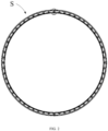
FIG. 2 ist eine axiale schematische Darstellung einer Dichtungsvorrichtung S gemäß einer ersten Ausführungsform der vorliegenden Erfindung. -
FIG. 3 ist eine vergrößerte dreidimensionale schematische Darstellung eines eingekreisten Teils inFIG. 2 . -
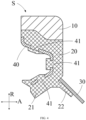
FIG. 4 ist eine Hälfte einer Schnittansicht der Dichtungsvorrichtung S gemäß der ersten Ausführungsform der vorliegenden Erfindung senkrecht zu einer axialen Richtung. -
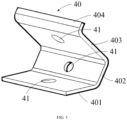
FIG. 5 ist eine schematische Darstellung eines elastischen Elements 40 gemäß der ersten Ausführungsform der vorliegenden Erfindung. -
FIG. 6 ist eine vergrößerte schematische Darstellung des eingekreisten Teils inFIG. 2 . -
FIG. 7 ist eine schematische, teilweise angeschnittene Darstellung einer Dichtungsvorrichtung S gemäß einer zweiten Ausführungsform der vorliegenden Erfindung. -
FIG. 8 ist eine schematische Darstellung eines elastischen Elements 40 gemäß der zweiten Ausführungsform der vorliegenden Erfindung. -
FIG. 9 ist eine Hälfte einer Schnittansicht der Dichtungsvorrichtung S gemäß der zweiten Ausführungsform der vorliegenden Erfindung senkrecht zu einer axialen Richtung. - Beispielhafte Ausführungsformen der vorliegenden Erfindung werden nachstehend unter Bezugnahme auf die beiliegenden Zeichnungen beschrieben. Es versteht sich, dass diese konkreten Beschreibungen Fachleute nur lehren sollen, wie die vorliegende Erfindung zu realisieren ist, und weder alle möglichen Variationen der vorliegenden Erfindung erschöpfend darlegen noch den Schutzumfang der vorliegenden Erfindung einschränken sollen.
- Sofern nicht anders angegeben, bezeichnet A unter Bezugnahme auf
FIG. 4 undFIG. 9 eine axiale Richtung der Dichtungsvorrichtung S und die axiale Richtung A stimmt mit einer axialen Richtung eines Lagers überein; und R bezeichnet eine radiale Richtung der Dichtungsvorrichtung S und die radiale Richtung R stimmt mit einer radialen Richtung des Lagers überein. - Unter Bezugnahme auf
FIG. 2 bis FIG. 9 wird die Dichtungsvorrichtung S des Lagers gemäß der vorliegenden Erfindung beschrieben. - Zunächst wird unter Bezugnahme auf
FIG. 2 bis FIG. 6 eine Dichtungsvorrichtung S gemäß der ersten Ausführungsform der vorliegenden Erfindung beschrieben. - Wie in
FIG. 2 gezeigt, ist die Dichtungsvorrichtung S ringförmig. - Weiter unter Bezugnahme auf
FIG. 3 undFIG. 4 umfasst die Dichtungsvorrichtung S einen Rahmen 10, eine Dichtungskomponente 20, eine Zusatzlippe 30 und elastische Elemente 40, die alle ringförmig sind. - In der vorliegenden Ausführungsform ist die Dichtungskomponente 20 an einer inneren Umfangsseite des Rahmens 10 angeordnet. Der Rahmen 10 ist konfiguriert, um mit einem Außenring (in der vorliegenden Ausführungsform auch als erster Ring bezeichnet) eines Lagers in Presspassung verbunden zu sein, und die Dichtungskomponente 20 ist konfiguriert, um an einem Innenring (in der vorliegenden Ausführungsform auch als zweiter Ring bezeichnet) des Lagers anzuliegen, und ist relativ zu dem Innenring drehbar.
- Ein Herstellungsmaterial des Rahmens 10 umfasst Gewebe, beispielsweise Baumwolle oder Nylon. Daher weist der Rahmen 10 eine hohe Flexibilität auf, ist einfach herzustellen und kostengünstig und lässt sich leicht an dem Außenring des Lagers zusammenbauen. Solche Vorteile sind besonders offensichtlich für den Rahmen 10 mit einem großen Durchmesser (beispielsweise etwa 1 m oder mehr als 1 m).
- Ein Herstellungsmaterial der Dichtungskomponente 20 ist beispielsweise Gummi. Die Dichtungskomponente 20 ist beispielsweise durch einen Vulkanisierungsvorgang mit dem Rahmen 10 verbunden.
- Unter Berücksichtigung der beispielhaft in
FIG. 4 gezeigten Ausrichtung als Beispiel ist eine linke Seite der Dichtungsvorrichtung S in der Figur die Innenseite (d. h. eine Schmiermittelseite) des Lagers und eine rechte Seite der Dichtungsvorrichtung S ist die Außenseite (d. h. eine Luftseite) des Lagers. - Die Dichtungskomponente 20 umfasst eine Hauptlippe 21 und eine Hilfslippe 22. Relativ zu einer Ebene senkrecht zu einer axialen Richtung A neigt sich die Hauptlippe 21 zur Innenseite und die Hilfslippe 22 neigt sich zur Außenseite.
- Eine Vielzahl von elastischen Elementen 40 ist bereitgestellt, und die Vielzahl von elastischen Elementen 40 ist gleichmäßig in einer Umfangsrichtung der Dichtungskomponente 20 verteilt.
- Die elastischen Elemente 40 sind ungefähr C-förmig, und Öffnungen mit C-Form sind ungefähr der Innenseite des Lagers zugewandt.
- Die elastischen Elemente 40 sind teilweise mit der Hauptlippe 21 verbunden, um sicherzustellen, dass die elastischen Elemente 40 eine Komponentenkraft mindestens in einer radialen Richtung R auf die Hauptlippe 21 ausüben können, wenn die Dichtungsvorrichtung S an dem Lager montiert ist, sodass die Hauptlippe 21 in engem Kontakt mit dem Innenring steht.
- Unter Bezugnahme auf
FIG. 5 umfasst das elastische Element 40 währenddessen drei blechartige Teile (ein erstes Biegeblech 401, ein zweites Biegeblech 402 und ein drittes Biegeblech 403), die miteinander verbunden und schräg zueinander angeordnet sind. Vorzugsweise ist ein von dem zweiten Biegeblech 402 entferntes Endteil des dritten Biegeblechs 403 ferner mit einem vierten Biegeblech 404 verbunden; eine Biegerichtung des vierten Biegeblechs 404 ist entgegengesetzt zu einer Öffnungsrichtung des C-förmigen elastischen Elements 40; und das vierte Biegeblech 404 erstreckt sich in Richtung des Rahmens 10. Eine der Öffnung der C-Form zugewandte Oberfläche des elastischen Elements 40 fällt im Wesentlichen mit einer der Innenseite zugewandten Oberfläche der Dichtungskomponente 20 zusammen. - Unter Bezugnahme auf
FIG. 4 undFIG. 5 ist das erste Biegeblech 401 an die (axiale) Innenseite der Hauptlippe 21 gebunden und erstreckt sich in Richtung einer radialen Außenseite, während es sich zu einer axialen Außenseite erstreckt. Das zweite Biegeblech 402 ist an ein schmales Teil eines radialen mittleren Teils der Dichtungskomponente 20 gebunden, befindet sich an einer (axialen) Innenseite des schmalen Teils und erstreckt sich im Wesentlichen entlang einer radialen Richtung R. Das dritte Biegeblech 403 ist an ein mit dem Rahmen 10 verbundenes Basisteil der Dichtungskomponente 20 gebunden; und das dritte Biegeblech 403 erstreckt sich in Richtung der radialen Außenseite, während es sich in Richtung der axialen Innenseite erstreckt. Das erste Biegeblech 401 und das dritte Biegeblech 403 sind einander in der radialen Richtung R zugewandt, sodass eine elastische dem Innenring des Lagers zugewandte Kraft auf die Hauptlippe 21 ausgeübt werden kann. - Das elastische Element 40 ist mit mehreren (in der vorliegenden Ausführungsform drei) Durchgangslöchern 41 (auch als Gummiüberlauflöcher bezeichnet) versehen. Das elastische Element 40 und die Dichtungskomponente 20 sind beispielsweise durch einen Vulkanisierungsvorgang miteinander verbunden. Bei dem Vulkanisierungsvorgang kann halbfester Gummi durch die Durchgangslöcher 41 gelangen und die elastischen Elemente 40 teilweise umhüllen, d. h., es ist gezeigt, dass die Dichtungskomponente 20 teilweise durch die Durchgangslöcher 41 verläuft, sodass das elastische Element 40 fest mit der Dichtungskomponente 20 verbunden ist.
- Vorzugsweise ist jedes des ersten Biegeblechs 401, des zweiten Biegeblechs 402 und des dritten Biegeblechs 403 mit mindestens einem Durchgangsloch 41 versehen.
- Die dem Innenring und der Innenseite des Lagers zugewandte Oberfläche der Hauptlippe 21 ist in Richtung der Außenseite teilweise vertieft, um eine Vielzahl von Ölpumpnuten 23 zu bilden. Vorzugsweise ist die Vielzahl von Ölpumpnuten 23 gleichmäßig in der Umfangsrichtung der Dichtungskomponente 20 verteilt.
- In der vorliegenden Ausführungsform umfasst die Ölpumpnut 23 unter Bezugnahme auf
FIG. 3 undFIG. 6 vier Innenoberflächen, um eine Trompetenform zu bilden (je näher die Öffnung der Ölpumpnut 23 an Innenseite des Lagers ist, umso größer ist deren Öffnung). Die vier Innenoberflächen sind eine erste Fläche 231, eine zweite Fläche 232, eine dritte Fläche 233 bzw. eine vierte Fläche 234. Die vierte Fläche 234 befindet sich am tiefsten Teil der Ölpumpnut 23 und die vierte Fläche 234 ist im Wesentlichen parallel zu der Oberfläche senkrecht zu der axialen Richtung A. Die erste Fläche 231 und die dritte Fläche 233 befinden sich an zwei Seiten der vierten Fläche 234 in einer Umfangsrichtung, und die zweite Fläche 232 befindet sich auf einer radialen Außenseite der vierten Fläche 234 und ist sowohl mit der ersten Fläche 231 als auch der dritten Fläche 233 verbunden. - Durch die obige Anordnung der Ölpumpnut 23 kann an der Innenseite verspritztes Öl mit hoher Wahrscheinlichkeit auf die geneigten Innenoberflächen (hauptsächlich die erste Fläche 231, die zweite Fläche 232 und die dritte Fläche 233) der Ölpumpnut 23 auftreffen, wodurch es durch diese geneigten Innenoberflächen zurückgepumpt wird und sich nicht leicht in der Nähe der Hauptlippe 21 ansammelt oder sogar an der Außenseite des Lagers austritt.
- Es versteht sich, dass die Ölpumpnut 23 nicht darauf beschränkt ist, aus vier Innenoberflächen zusammengesetzt zu sein, sie kann beispielsweise mehr geneigte Innenoberflächen umfassen, oder die Innenoberflächen der Ölpumpnut 23 können auch gekrümmte Oberflächen umfassen.
- Unter weiterer Bezugnahme auf
FIG. 3 undFIG. 4 kann die Hilfslippe 22 in Kontakt mit dem Innenring stehen oder nicht, wenn die Hauptlippe 21 in Kontakt mit dem Innenring steht. Wenn außerdem die Hilfslippe 22 ebenfalls mit dem Innenring in Kontakt steht, steht die Hilfslippe 22 mit einer ziemlich geringen radialen Kraft in Kontakt mit dem Innenring, und die radiale Kraft, mit der die Hilfslippe 22 an dem Innenring anliegt, ist kleiner als eine radiale Kraft, mit der die Hauptlippe 21 an dem Innenring anliegt. - Eine Zusatzlippe 30 ist mit der Hilfslippe 22 verbunden. Vorzugsweise ist die Zusatzlippe 30 an einer der Außenseite zugewandten Oberfläche der Hilfslippe 22 angeordnet. Vorzugsweise ist die Zusatzlippe 30 klebend mit der Hilfslippe 22 verbunden.
- Die Zusatzlippe 30 ist aus einem Material mit guter Luftdurchlässigkeit hergestellt. Vorzugsweise umfasst ein Herstellungsmaterial der Zusatzlippe 30 Filz. Vorzugsweise steht die Zusatzlippe 30 in Kontakt mit dem Innenring, wenn die Dichtungsvorrichtung S an dem Lager montiert ist.
- In einem ersten Aspekt spielt die Zusatzlippe 30 eine Rolle beim Verhindern, dass Fremdstoffe an der Außenseite in die Innenseite des Lagers eindringen; in einem zweiten Aspekt spielt die Zusatzlippe 30 eine Rolle beim Schützen der Hilfslippe 22, sodass die Hilfslippe 22 nicht in direktem Kontakt mit den äußeren Fremdstoffen und nicht in Kontakt mit dem Innenring stehen muss, um nicht leicht zu verschleißen, und die aus Filz hergestellte Zusatzlippe 30 weist eine gute Festigkeit auf und reißt nicht einfach; und in einem dritten Aspekt kann die Zusatzlippe 30 beispielsweise verhindern, dass Wasser an der Außenseite in die Innenseite des Lagers eindringt, und währenddessen schränkt die Zusatzlippe 30 die Zirkulation von Luft nicht ein, sodass Luftdrücke an zwei axialen Seiten der Hilfslippe 22 ausgeglichen oder nahezu ausgeglichen gehalten werden können.
- Die zweite Ausführungsform gemäß der vorliegenden Erfindung wird nachstehend unter Bezugnahme auf
FIG. 7 bis FIG. 9 beschrieben. Komponenten, die dieselbe oder eine ähnliche Konstruktion oder Funktion wie diejenigen in der ersten Ausführungsform aufweisen, sind mit denselben Bezugszeichen bezeichnet, und auf eine detaillierte Beschreibung dieser Komponenten wird verzichtet. - In der vorliegenden Ausführungsform ist die Dichtungskomponente 20 an einer Außenumfangsseite des Rahmens 10 angeordnet. Der Rahmen 10 ist konfiguriert, um mit einem Innenring (in der vorliegenden Ausführungsform auch als erster Ring bezeichnet) eines Lagers in Presspassung verbunden zu sein, wobei sich der Rahmen 10 und der Innenring nicht relativ zueinander drehen, die Dichtungskomponente 20 ist konfiguriert, um an einem Außenring (in der vorliegenden Ausführungsform auch als zweiter Ring bezeichnet) des Lagers anzuliegen, und die Dichtungskomponente 20 ist relativ zu dem Außenring drehbar.
- In der vorliegenden Ausführungsform sind die elastischen Elemente 40 ferner mit mehreren (zwei in der vorliegenden Ausführungsform) Positionierungslöchern 42 versehen, mit Ausnahme von Durchgangslöchern 41, durch die Gummi verläuft. Die Positionierungslöcher 42 werden verwendet, um Positionierungsstifte an einer Vulkanisierungsform während des Vulkanisierungsvorgangs zum Verbinden der elastischen Elemente 40 mit der Dichtungskomponente 20 auszurichten, um die Positionierungsgenauigkeit der elastischen Elemente 40 an der Dichtungskomponente 20 sicherzustellen.
- Es versteht sich, dass einige Aspekte oder Merkmale der vorstehend genannten Ausführungsformen geeignet kombiniert werden können.
- Es versteht sich, dass die vorliegende Erfindung ferner ein Lager bereitstellt, das die vorstehend genannte Dichtungsvorrichtung S umfasst. Vorzugsweise weist das Lager einen Durchmesser von 1 Meter bis zu mehreren Metern auf. Vorzugsweise ist das Lager ein Lager, das für eine Hauptwelle eines Windkraftgenerators verwendet wird.
- Einige der vorteilhaften Wirkungen der vorstehend genannten Ausführungsformen der vorliegenden Erfindung werden nachstehend kurz beschrieben.
- (i) Eine Vielzahl von C-förmigen elastischen Elementen 40 stellt an unterschiedlichen Positionen in der Umfangsrichtung gleichmäßig radiale Kräfte für die Dichtungskomponente 20 bereit, um an dem zweiten Ring des Lagers anzuliegen, sodass die Dichtungskomponente 20 in engem Kontakt mit dem zweiten Ring stehen kann, und die Dichtungsvorrichtung S weist eine gute Dichtungswirkung auf.
- (ii) Die Gummiüberlauflöcher (Durchgangslöcher 41) an den elastischen Elementen 40 ermöglichen, dass die beispielsweise aus Gummi hergestellte Dichtungskomponente 20 durch diese verläuft, und die elastischen Elemente 40 und die Dichtungskomponente 20 sind fest verbunden.
- (iii) Die trompetenförmigen Ölpumpnuten 23 können Schmiermittel nahe der Hauptlippe 21 wirksam zur Innenseite des Lagers pumpen, und das Schmiermittel kann nicht leicht austreten.
- (iv) Die Zusatzlippe 30 kann verhindern, dass externe Verunreinigungen in die Innenseite des Lagers eindringen, und währenddessen die Hilfslippe 22 davor schützen, dass sie leicht reißt oder abgenutzt wird, und die gute Luftdurchlässigkeit und Wasserbeständigkeit der Zusatzlippe 30 ermöglichen ausgeglichene Drücke an zwei axialen Seiten der Hilfslippe 22.
- Es versteht sich, dass die vorstehend genannten Ausführungsformen nur beispielhaft sind und die vorliegende Erfindung nicht einschränken sollen. Fachleute können verschiedene Modifikationen und Änderungen an den vorstehend genannten Ausführungsformen gemäß der Lehre der vorliegenden Erfindung vornehmen, ohne vom Schutzumfang der vorliegenden Erfindung abzuweichen. Zum Beispiel:
- (i) Obwohl ein Innenring eines Hauptwellenlagers eines Windkraftgenerators üblicherweise ein rotierender Ring ist und ein Außenring ein unbeweglicher Ring ist, beschränkt die vorliegende Erfindung nicht den Betriebszustand des Innenrings und des Außenrings des Lagers. Beispielsweise kann in den zwei vorstehend genannten Ausführungsformen ein beliebiger des Innenrings und des Außenrings ein rotierender Ring sein, und der andere kann ein unbeweglicher Ring sein.
- (ii) Die vorliegende Erfindung schränkt Formen und Mengen der Durchgangslöcher 41 und der Positionierungslöcher 42 der elastischen Elemente 40 nicht ein. Beispielsweise können die Durchgangslöcher 41 kreisförmig, quadratisch oder von anderen Formen sein.
- (iii) Die elastischen Elemente 40 der vorliegenden Erfindung können auch nicht C-förmig, sondern beispielsweise L-förmig oder Z-förmig sein, oder das elastische Element 40 umfasst mindestens zwei Bereiche, die zueinander gebogen sind. Wenn die Dichtungsvorrichtung an dem Lager montiert ist, befinden sich die elastischen Elemente 40 in einem komprimierten Zustand, sodass die elastischen Elemente 40 eine elastische Kraft auf die Dichtungskomponente 20 ausüben können, sodass die Dichtungskomponente 20 gegen den zweiten Ring gedrückt wird.
- Unter Bezugnahme auf
FIG. 5 kann das elastische Element beispielsweise, wenn das elastische Element im Wesentlichen L-förmig ist, ein erstes Biegeblech 401 und ein zweites Biegeblech 402 umfassen, wie inFIG. 5 gezeigt. -
- B1
- Außenring;
- B2
- Innenring;
- S1
- Rahmen;
- S2
- Dichtungskomponente;
- S3
- Feder;
- S21
- Hauptlippe;
- S22
- Hilfslippe;
- f
- geneigte Oberfläche;
- S
- Dichtungsvorrichtung;
- 10
- Rahmen;
- 20
- Dichtungskomponente;
- 21
- Hauptlippe;
- 22
- Hilfslippe;
- 23
- Ölpumpnut;
- 231
- erste Fläche;
- 232
- zweite Fläche;
- 233
- dritte Fläche;
- 234
- vierte Fläche;
- 30
- Zusatzlippe;
- 40
- elastisches Element;
- 41
- Durchgangsloch;
- 42
- Positionierungsloch;
- A
- axiale Richtung;
- R
- radiale Richtung.
Claims (16)
- Dichtungsvorrichtung eines Lagers, umfassend einen Rahmen (10), eine Dichtungskomponente (20) und eine Vielzahl von elastischen Elementen (40), wobei der Rahmen (10) und die Dichtungskomponente (20) beide ringförmig und miteinander verbunden sind; der Rahmen (10) konfiguriert ist, um an einem ersten Ring des Lagers befestigt zu sein; die Dichtungskomponente (20) konfiguriert ist, um an einem zweiten Ring des Lagers anzuliegen, wobeidie Vielzahl von elastischen Elementen (40) in Umfangsrichtung der Dichtungskomponente (20) in Abständen verteilt sind unddie elastischen Elemente (40) verwendet werden, um eine elastische Kraft auf die Dichtungskomponente (20) auszuüben, sodass die Dichtungskomponente (20) gegen den zweiten Ring gedrückt wird.
- Dichtungsvorrichtung nach Anspruch 1, dadurch gekennzeichnet, dass die elastischen Elemente (40) C-förmig sind.
- Dichtungsvorrichtung nach Anspruch 1, dadurch gekennzeichnet, dass ein Herstellungsmaterial des Rahmens (10) Gewebe umfasst.
- Dichtungsvorrichtung nach Anspruch 1, dadurch gekennzeichnet, dass ein Herstellungsmaterial der Dichtungskomponente (20) Gummi umfasst.
- Dichtungsvorrichtung nach Anspruch 4, dadurch gekennzeichnet, dass die Dichtungskomponente (20) und die elastischen Elemente (40) durch einen Vulkanisierungsvorgang miteinander verbunden sind.
- Dichtungsvorrichtung nach Anspruch 1, dadurch gekennzeichnet, dass mehrere Durchgangslöcher (41) an den elastischen Elementen (40) ausgebildet sind und die Dichtungskomponente (20) teilweise durch die Durchgangslöcher (41) verläuft.
- Dichtungsvorrichtung nach Anspruch 1, dadurch gekennzeichnet, dass mehrere Positionierungslöcher (42) an den elastischen Elementen (40) ausgebildet sind und die Positionierungslöcher (42) verwendet werden, um beim Unterstützen des Bestimmens der Umfangspositionen der elastischen Elemente (40) an der Dichtungskomponente (20) mit Positionierungsvorrichtungen an einer Form zusammenzuwirken.
- Dichtungsvorrichtung nach Anspruch 1, dadurch gekennzeichnet, dass eine dem zweiten Ring und einem inneren Seitenbereich des Lagers zugewandte Fläche der Dichtungskomponente (20) teilweise in Richtung einer Außenseite der Dichtungsvorrichtung vertieft ist, um eine Vielzahl von Ölpumpnuten (23) zu bilden, und die Vielzahl von Ölpumpnuten (23) in Umfangsrichtung der Dichtungskomponente (20) verteilt sind.
- Dichtungsvorrichtung nach Anspruch 8, dadurch gekennzeichnet, dass die Öffnungen der Ölpumpnuten (23) umso größer sind, je näher sie in Richtung einer Innenseite des Lagers sind.
- Dichtungsvorrichtung nach Anspruch 1, dadurch gekennzeichnet, dass die Dichtungskomponente (20) eine Hauptlippe (21) und eine Hilfslippe (22) umfasst, wobei sich die Hauptlippe (21) in einer axialen Richtung der Dichtungskomponente (20) zu einer Seite neigt, die Hilfslippe (22) sich in axialer Richtung zu der anderen Seite neigt, die Hauptlippe (21) verwendet wird, um der Innenseite des Lagers zugewandt zu sein, und die Hilfslippe (22) verwendet wird, um einer Außenseite des Lagers zugewandt zu sein.
- Dichtungsvorrichtung nach Anspruch 10, dadurch gekennzeichnet, dass die Hauptlippe (21) verwendet wird, um mit dem zweiten Ring in Kontakt zu stehen.
- Dichtungsvorrichtung nach Anspruch 1, dadurch gekennzeichnet, dass die Dichtungsvorrichtung ferner eine Zusatzlippe (30) umfasst, wobei die Zusatzlippe (30) konfiguriert ist, um der Außenseite des Lagers zugewandt zu sein und in Kontakt mit dem zweiten Ring zu stehen; und ein Herstellungsmaterial der Zusatzlippe (30) Luftdurchlässigkeit aufweist.
- Dichtungsvorrichtung nach Anspruch 10, dadurch gekennzeichnet, dass die Hilfslippe (22) ferner mit einer Zusatzlippe (30) versehen ist, wobei die Zusatzlippe (30) verwendet wird, um mit dem zweiten Ring in Kontakt zu stehen, und ein Herstellungsmaterial der Zusatzlippe (30) Filz umfasst.
- Dichtungsvorrichtung nach einem der Ansprüche 1 bis 13, dadurch gekennzeichnet, dass ein Innendurchmesser des Rahmens (10) nicht weniger als 1 m beträgt.
- Lager, umfassend einen ersten Ring und einen zweiten Ring, die ineinander passen und relativ zueinander drehbar sind, dadurch gekennzeichnet, dass das Lager ferner die Dichtungsvorrichtung nach einem der Ansprüche 1 bis 14 umfasst.
- Lager nach Anspruch 15, dadurch gekennzeichnet, dass das Lager ein Hauptwellenlager eines Windkraftgenerators ist.
Applications Claiming Priority (1)
| Application Number | Priority Date | Filing Date | Title |
|---|---|---|---|
| PCT/CN2020/121369 WO2022077412A1 (zh) | 2020-10-16 | 2020-10-16 | 轴承的密封装置与轴承 |
Publications (2)
| Publication Number | Publication Date |
|---|---|
| EP4230898A1 true EP4230898A1 (de) | 2023-08-23 |
| EP4230898A4 EP4230898A4 (de) | 2024-07-10 |
Family
ID=81208743
Family Applications (1)
| Application Number | Title | Priority Date | Filing Date |
|---|---|---|---|
| EP20957190.0A Withdrawn EP4230898A4 (de) | 2020-10-16 | 2020-10-16 | Dichtungsvorrichtung für lager und lager |
Country Status (4)
| Country | Link |
|---|---|
| US (1) | US12372154B2 (de) |
| EP (1) | EP4230898A4 (de) |
| CN (1) | CN115698562B (de) |
| WO (1) | WO2022077412A1 (de) |
Family Cites Families (22)
| Publication number | Priority date | Publication date | Assignee | Title |
|---|---|---|---|---|
| US2249141A (en) * | 1936-04-14 | 1941-07-15 | Nat Oil Seal Co | Fluid seal |
| US4531747A (en) * | 1982-11-01 | 1985-07-30 | Nippon Oil Seal Industry Co., Ltd. | Extended wear annular oil seal |
| US6050570A (en) * | 1998-01-30 | 2000-04-18 | The Timken Company | Seal with bi-modulus lip |
| DE102008025725A1 (de) * | 2008-05-29 | 2009-12-10 | Rothe Erde Gmbh | Dichtungssystem |
| US20100322544A1 (en) * | 2009-06-22 | 2010-12-23 | Amsted Rail Company, Inc. | Bearing assembly having a dust seal arrangement with contacting and non-contacting dust seals |
| ES2985981T3 (es) * | 2012-04-12 | 2024-11-08 | Skf Ab | Dispositivo de rodamiento con al menos una unidad de obturación |
| CN203023491U (zh) | 2012-07-16 | 2013-06-26 | 孙建民 | 新型弹簧蓄能密封圈 |
| CN202834078U (zh) | 2012-09-14 | 2013-03-27 | 青岛开世密封工业有限公司 | 具有防尘功能的主动散热密封圈 |
| CN203939998U (zh) | 2014-02-26 | 2014-11-12 | 北京裕泰行新材料科技有限公司 | 密封圈 |
| JP6663630B2 (ja) * | 2014-04-16 | 2020-03-13 | Nok株式会社 | 密封装置 |
| CN205064594U (zh) | 2015-08-28 | 2016-03-02 | 舍弗勒技术股份两合公司 | 密封式圆柱滚子轴承 |
| JP6583093B2 (ja) | 2016-03-29 | 2019-10-02 | 日本精工株式会社 | 密封装置及び密封装置付転がり軸受ユニット |
| JP6839563B2 (ja) | 2017-02-21 | 2021-03-10 | Nok株式会社 | 密封装置 |
| GB2562205B (en) | 2017-03-16 | 2022-04-27 | Walker & Co James | Composite structure for sealing products |
| CN108591467A (zh) * | 2018-04-20 | 2018-09-28 | 舍弗勒技术股份两合公司 | 密封结构 |
| CN108533619A (zh) * | 2018-04-28 | 2018-09-14 | 舍弗勒技术股份两合公司 | 密封结构 |
| CN108591471A (zh) * | 2018-06-22 | 2018-09-28 | 舍弗勒技术股份两合公司 | 轴承及密封装置 |
| CN111712659B (zh) * | 2018-07-24 | 2023-03-21 | Nok株式会社 | 密封装置 |
| CN110762218B (zh) | 2018-07-26 | 2024-04-12 | 舍弗勒技术股份两合公司 | 密封圈 |
| CN110259949A (zh) | 2019-05-07 | 2019-09-20 | 舍弗勒技术股份两合公司 | 密封装置 |
| CN211550530U (zh) * | 2020-02-09 | 2020-09-22 | 浙江轩孚自动变速器有限公司 | 一种变速器油泵油封 |
| EP3926189B1 (de) * | 2020-06-17 | 2024-04-24 | Siemens Gamesa Renewable Energy A/S | Lageranordnung einer windturbine |
-
2020
- 2020-10-16 US US18/031,967 patent/US12372154B2/en active Active
- 2020-10-16 WO PCT/CN2020/121369 patent/WO2022077412A1/zh not_active Ceased
- 2020-10-16 EP EP20957190.0A patent/EP4230898A4/de not_active Withdrawn
- 2020-10-16 CN CN202080101824.1A patent/CN115698562B/zh active Active
Also Published As
| Publication number | Publication date |
|---|---|
| WO2022077412A1 (zh) | 2022-04-21 |
| CN115698562A (zh) | 2023-02-03 |
| EP4230898A4 (de) | 2024-07-10 |
| CN115698562B (zh) | 2025-11-21 |
| US20230392649A1 (en) | 2023-12-07 |
| US12372154B2 (en) | 2025-07-29 |
Similar Documents
| Publication | Publication Date | Title |
|---|---|---|
| DE69825823T2 (de) | Lager mit Doppeldichtung | |
| DE102017110087B4 (de) | Eine Kassettendichtungsvorrichtung sowie ein Lager mit einer solchen Kassettendichtungsvorrichtung | |
| DE112019003837T5 (de) | Dicht-element und lager-vorrichtung für ein rad mit dicht-element | |
| DE202017101822U1 (de) | Dichtungsvorrichtung und Wälzlagereinheit mit demselben | |
| DE10018273A1 (de) | Bürstendichtung | |
| DE102018217020A1 (de) | Abdichtvorrichtung | |
| DE112009004785T5 (de) | Dichtvorrichtung für Wälziager | |
| DE102017113043A1 (de) | Triebrad mit Drehschwingungsdämpfungseinrichtung | |
| DE102017111664A1 (de) | Triebrad mit Drehschwingungsdämpfungseinrichtung | |
| DE202020100769U1 (de) | Nabenlager | |
| DE112015002746B4 (de) | Wälzlager | |
| DE102019217379A1 (de) | Wälzlageranordnung | |
| DE102014102368A1 (de) | Kegelrollenlager-einheit | |
| DE3118469A1 (de) | "fluiddichtung" | |
| DE102009055151A1 (de) | Geteiltes Gleitlager für eine Kurbelwelle in einem Verbrennungsmotor und geteilte Gleitlagervorrichtung | |
| DE102018114677A1 (de) | Wälzlager und Dichtungsanordnung mit mindestens zwei Dichtlippen | |
| DE69815001T2 (de) | Wasserpumpe und ihr Herstellungsverfahren | |
| DE19811040B4 (de) | Axiallaufscheibe | |
| DE102023201191A1 (de) | Lageranordnung für Lebensmittelanwendungen | |
| DE202014103365U1 (de) | Rollenlager-Dichtungsvorrichtung und Rollenlager | |
| DE102017217136A1 (de) | Dichtung und Dichtungsmechanismus | |
| DE102019204877A1 (de) | Dichtungsstruktur und diese Dichtungsstruktur aufweisende Vorrichtung | |
| EP4230898A1 (de) | Dichtungsvorrichtung für lager und lager | |
| DE112018001585T5 (de) | Fahrzeugrad-lagervorrichtung | |
| DE102018108591A1 (de) | Dichtungsanordnung, Dichtung und Tretkurbelanordnung |
Legal Events
| Date | Code | Title | Description |
|---|---|---|---|
| STAA | Information on the status of an ep patent application or granted ep patent |
Free format text: STATUS: THE INTERNATIONAL PUBLICATION HAS BEEN MADE |
|
| PUAI | Public reference made under article 153(3) epc to a published international application that has entered the european phase |
Free format text: ORIGINAL CODE: 0009012 |
|
| STAA | Information on the status of an ep patent application or granted ep patent |
Free format text: STATUS: REQUEST FOR EXAMINATION WAS MADE |
|
| 17P | Request for examination filed |
Effective date: 20230516 |
|
| AK | Designated contracting states |
Kind code of ref document: A1 Designated state(s): AL AT BE BG CH CY CZ DE DK EE ES FI FR GB GR HR HU IE IS IT LI LT LU LV MC MK MT NL NO PL PT RO RS SE SI SK SM TR |
|
| DAV | Request for validation of the european patent (deleted) | ||
| DAX | Request for extension of the european patent (deleted) | ||
| A4 | Supplementary search report drawn up and despatched |
Effective date: 20240611 |
|
| RIC1 | Information provided on ipc code assigned before grant |
Ipc: F16J 15/3248 20160101ALI20240605BHEP Ipc: F16J 15/3208 20160101ALI20240605BHEP Ipc: F16C 19/00 20060101ALI20240605BHEP Ipc: F16C 33/78 20060101ALI20240605BHEP Ipc: F16J 15/3212 20160101AFI20240605BHEP |
|
| STAA | Information on the status of an ep patent application or granted ep patent |
Free format text: STATUS: THE APPLICATION IS DEEMED TO BE WITHDRAWN |
|
| 18D | Application deemed to be withdrawn |
Effective date: 20250103 |