EP4230813A1 - Garniture d'écoulement avec récupération de chaleur pour une baignoire sanitaire - Google Patents
Garniture d'écoulement avec récupération de chaleur pour une baignoire sanitaire Download PDFInfo
- Publication number
- EP4230813A1 EP4230813A1 EP23154216.8A EP23154216A EP4230813A1 EP 4230813 A1 EP4230813 A1 EP 4230813A1 EP 23154216 A EP23154216 A EP 23154216A EP 4230813 A1 EP4230813 A1 EP 4230813A1
- Authority
- EP
- European Patent Office
- Prior art keywords
- drain
- cup
- fitting
- water
- opening
- Prior art date
- Legal status (The legal status is an assumption and is not a legal conclusion. Google has not performed a legal analysis and makes no representation as to the accuracy of the status listed.)
- Pending
Links
- XLYOFNOQVPJJNP-UHFFFAOYSA-N water Substances O XLYOFNOQVPJJNP-UHFFFAOYSA-N 0.000 claims abstract description 84
- 238000004804 winding Methods 0.000 claims abstract description 13
- 239000002699 waste material Substances 0.000 claims abstract description 6
- 238000009434 installation Methods 0.000 claims description 8
- 239000000463 material Substances 0.000 claims description 5
- 229910052751 metal Inorganic materials 0.000 claims description 2
- 239000002184 metal Substances 0.000 claims description 2
- 101150038956 cup-4 gene Proteins 0.000 description 6
- XEEYBQQBJWHFJM-UHFFFAOYSA-N Iron Chemical compound [Fe] XEEYBQQBJWHFJM-UHFFFAOYSA-N 0.000 description 2
- PXHVJJICTQNCMI-UHFFFAOYSA-N Nickel Chemical compound [Ni] PXHVJJICTQNCMI-UHFFFAOYSA-N 0.000 description 2
- 238000009428 plumbing Methods 0.000 description 2
- 229910001369 Brass Inorganic materials 0.000 description 1
- 229910000906 Bronze Inorganic materials 0.000 description 1
- BQCADISMDOOEFD-UHFFFAOYSA-N Silver Chemical compound [Ag] BQCADISMDOOEFD-UHFFFAOYSA-N 0.000 description 1
- 229910000831 Steel Inorganic materials 0.000 description 1
- RTAQQCXQSZGOHL-UHFFFAOYSA-N Titanium Chemical compound [Ti] RTAQQCXQSZGOHL-UHFFFAOYSA-N 0.000 description 1
- HCHKCACWOHOZIP-UHFFFAOYSA-N Zinc Chemical compound [Zn] HCHKCACWOHOZIP-UHFFFAOYSA-N 0.000 description 1
- 229910052782 aluminium Inorganic materials 0.000 description 1
- XAGFODPZIPBFFR-UHFFFAOYSA-N aluminium Chemical compound [Al] XAGFODPZIPBFFR-UHFFFAOYSA-N 0.000 description 1
- 239000010951 brass Substances 0.000 description 1
- 239000010974 bronze Substances 0.000 description 1
- 238000004140 cleaning Methods 0.000 description 1
- 239000002131 composite material Substances 0.000 description 1
- KUNSUQLRTQLHQQ-UHFFFAOYSA-N copper tin Chemical compound [Cu].[Sn] KUNSUQLRTQLHQQ-UHFFFAOYSA-N 0.000 description 1
- 238000005265 energy consumption Methods 0.000 description 1
- PCHJSUWPFVWCPO-UHFFFAOYSA-N gold Chemical compound [Au] PCHJSUWPFVWCPO-UHFFFAOYSA-N 0.000 description 1
- 229910052737 gold Inorganic materials 0.000 description 1
- 239000010931 gold Substances 0.000 description 1
- 238000010438 heat treatment Methods 0.000 description 1
- 238000007373 indentation Methods 0.000 description 1
- 229910052742 iron Inorganic materials 0.000 description 1
- 239000011133 lead Substances 0.000 description 1
- 229910052759 nickel Inorganic materials 0.000 description 1
- 230000001105 regulatory effect Effects 0.000 description 1
- 229910052709 silver Inorganic materials 0.000 description 1
- 239000004332 silver Substances 0.000 description 1
- 229910001220 stainless steel Inorganic materials 0.000 description 1
- 239000010935 stainless steel Substances 0.000 description 1
- 239000010959 steel Substances 0.000 description 1
- 239000010936 titanium Substances 0.000 description 1
- 229910052719 titanium Inorganic materials 0.000 description 1
- WFKWXMTUELFFGS-UHFFFAOYSA-N tungsten Chemical compound [W] WFKWXMTUELFFGS-UHFFFAOYSA-N 0.000 description 1
- 229910052721 tungsten Inorganic materials 0.000 description 1
- 239000010937 tungsten Substances 0.000 description 1
- 229910052725 zinc Inorganic materials 0.000 description 1
- 239000011701 zinc Substances 0.000 description 1
Images


Classifications
-
- E—FIXED CONSTRUCTIONS
- E03—WATER SUPPLY; SEWERAGE
- E03F—SEWERS; CESSPOOLS
- E03F5/00—Sewerage structures
- E03F5/04—Gullies inlets, road sinks, floor drains with or without odour seals or sediment traps
- E03F5/0407—Floor drains for indoor use
- E03F5/0408—Floor drains for indoor use specially adapted for showers
-
- E—FIXED CONSTRUCTIONS
- E03—WATER SUPPLY; SEWERAGE
- E03C—DOMESTIC PLUMBING INSTALLATIONS FOR FRESH WATER OR WASTE WATER; SINKS
- E03C1/00—Domestic plumbing installations for fresh water or waste water; Sinks
- E03C1/12—Plumbing installations for waste water; Basins or fountains connected thereto; Sinks
- E03C1/22—Outlet devices mounted in basins, baths, or sinks
-
- F—MECHANICAL ENGINEERING; LIGHTING; HEATING; WEAPONS; BLASTING
- F24—HEATING; RANGES; VENTILATING
- F24D—DOMESTIC- OR SPACE-HEATING SYSTEMS, e.g. CENTRAL HEATING SYSTEMS; DOMESTIC HOT-WATER SUPPLY SYSTEMS; ELEMENTS OR COMPONENTS THEREFOR
- F24D17/00—Domestic hot-water supply systems
- F24D17/0005—Domestic hot-water supply systems using recuperation of waste heat
-
- E—FIXED CONSTRUCTIONS
- E03—WATER SUPPLY; SEWERAGE
- E03C—DOMESTIC PLUMBING INSTALLATIONS FOR FRESH WATER OR WASTE WATER; SINKS
- E03C1/00—Domestic plumbing installations for fresh water or waste water; Sinks
- E03C2001/005—Installations allowing recovery of heat from waste water for warming up fresh water
-
- F—MECHANICAL ENGINEERING; LIGHTING; HEATING; WEAPONS; BLASTING
- F24—HEATING; RANGES; VENTILATING
- F24D—DOMESTIC- OR SPACE-HEATING SYSTEMS, e.g. CENTRAL HEATING SYSTEMS; DOMESTIC HOT-WATER SUPPLY SYSTEMS; ELEMENTS OR COMPONENTS THEREFOR
- F24D2200/00—Heat sources or energy sources
- F24D2200/16—Waste heat
- F24D2200/20—Sewage water
Definitions
- the present invention relates to a waste fitting for a sanitary tub, which can be a shower tub, bathtub or washbasin, with a housing in which a cup is arranged and which has an inlet line for cold water.
- the inlet line directs cold water from an inlet to an outlet and is routed around the cup with several turns inside the drain fitting. Heated water can be introduced to the cup from a drain opening of a sanitary tub via an inflow opening on the housing.
- the cup is surrounded by an annular chamber which is connected to a drain at a drain opening via an overflow element. A water level in the annular chamber is predetermined via the overflow element.
- the EP 3 372 939 A2 shows an expansion unit for integrating a heat exchanger, which has a drain pan, at least one heat exchange unit arranged in the drain pan, and a distribution element for distributing water over the heat exchange unit.
- the heat exchange unit has a plurality of pipe sections which follow one another sequentially and run essentially horizontally and cold water sequentially flows through and water sprinkles or flows over.
- the tube sections of the heat exchange unit run in the same vertical plane.
- the EP 3 372 939 A2 an odor trap that closes off a drain odour-tight from the entrance of the drain of the sanitary tub.
- the vertical arrangement of the tubes of the heat exchange unit means that parts of the heat exchange unit are not covered with water when water flows over them from the distribution element, which reduces the efficiency of the heat exchanger.
- the drain fitting for a sanitary tub comprises a housing, a cup and an inlet line, the inlet line conducting cold water from an inlet to an outlet and being routed around the cup with several turns.
- Heated water can be introduced from the sanitary tub through a drain opening of the sanitary tub via an inflow opening on the housing to the cup and the cup is surrounded by an annular chamber which is connected to a drain opening via an overflow element with an in particular tubular drain.
- a water level in the annular chamber is specified via the overflow element, the water level being formed by the overflow element in such a way that the windings are at least partially immersed in the water and are arranged under the water level in such a way that cold water flowing through the inlet line can be heated.
- the heat loss to the environment and the air is reduced, making it possible to effectively increase the temperature of the cold water and thus increase efficiency.
- the efficiency of the drain fitting is at least 20%, preferably at least 40%, and is in the sense of the first law of thermodynamics for a heat exchanger from the ratio of the thermal energy absorbed by the cold water to the thermal energy released by the heated water, i.e. the amount of the temperature increase of the cold water and the magnitude of the temperature difference of the heated water, calculable.
- the inlet line is bent upwards around the drain opening of the drain fitting, so that the windings are routed above the drain opening. This causes the water to flow past the coils of the inlet pipe and then through the drain opening to the overflow element and drain.
- This arrangement makes it easier to clean the drain fitting and in particular the drain, since the drain opening is freely accessible and preferably covered by a turn by less than 20% in plan view.
- the cup is designed to be removable from the housing, which simplifies cleaning of the drain fitting.
- the cup is preferably a cup siphon.
- a pipe for introducing the water from the sanitary tub is inserted into the cup and forms an odor trap.
- the tube may engage the cup as a dip tube and be positioned with the lower end below a water level in the cup.
- a collecting element, for example a sieve, which can be removed through the inflow opening can optionally be provided on the pipe in order to catch hair at the inflow opening on the housing so that it cannot clog the drain fitting.
- the cup has at least one opening or recess on the side opposite the overflow element so that water flows into the annular chamber along the turns on either side of the cup to the drain opening. This promotes a turbulent flow of the draining water, which increases the efficiency of the drain fitting.
- the cup can have at least one opening in the form of a recess on an upper edge of a side wall on the side opposite the drain opening, so that the heated water essentially flows through the recess at the upper edge.
- the flow direction of the water flowing out of the cup can be specified via the indentation, ie the lowering of the upper edge on the cup.
- the overflow element for specifying a water level in the annular chamber of the drain fitting is preferably designed as a tube bent upwards.
- the overflow element can also be designed as a wall element in a tube.
- the inlet line is designed in the form of a first helix and at least one other helix that runs in opposite directions, with the first helix having a higher winding radius than at least one other helix that has smaller radii inside the drain fitting around the cup.
- the resulting increased length and outer surface of the feed line allows for improved efficiency.
- the annular chamber of the drain fitting housing has an outside diameter of 100 mm to 500 mm, preferably 170 mm to 250 mm.
- the feed line is in the form of a helix having a length of 1 m to 10 m, preferably 3 m to 7 m, and an outer diameter of 10 mm to 20 mm, preferably 12 mm to 16 mm, and an inner diameter of 8 mm to 18 mm, preferably 10 mm to 14 mm.
- the inlet pipe has a large area for heat transfer, which enables effective heating of cold water.
- the feed line is preferably made of a material with a heat transfer coefficient of between 15 W/mK and 750 W/mK, preferably between 190 W/mK and 450 W/mK. This leads to high efficiency.
- Metal e.g. copper, aluminum, brass, bronze, silver, gold, stainless steel, steel, zinc, iron, nickel, lead, titanium, tungsten, etc., is preferably used as the material for the feed line.
- the wall of the inlet pipe can be made of a single material or a composite of different materials.
- the drain fitting is mounted in a plumbing fixture having a plumbing tub that includes a cold water line and a hot water line connected to a mixer tap.
- the cold water line is also connected to the inlet of the supply line and the outlet of the supply line to the mixing valve.
- the installation device preferably has a valve that enables the water temperature in the mixing fitting to be controlled, the heated water from the supply line being able to be switched on, which reduces the energy consumption of the installation device.
- a drain fitting 1 is shown in an installation situation.
- the drain fitting comprises a housing 3 with an upper inflow opening 13 over which a drain opening 20 of a sanitary tub 2 is mounted.
- a cover 11 is provided on the drain opening 20 and the sanitary tub 2 is connected to the inflow opening 13 in a sealed manner via a seal 12 .
- the drain fitting 1 comprises a housing 3 with an annular chamber 14 in which a cup-shaped Becher4 is located.
- An inlet pipe 6 with several turns leads cold water around the cup 4.
- the water which drains from the sanitary tub 2 through the inflow opening 13, flows over a lowered edge of the cup 4 through a drain opening 19 in the annular chamber 14 to an overflow element 5.
- Through an opening is formed in the side wall of the cup 4 at the lowered edge, which is arranged on the opposite side to the drain opening 29 .
- the overflow element 5 specifies a water level 10 within the ring-shaped chamber 14 of the housing 3 of the drain fitting 1 , so that the windings of the inlet line 6 are at least partially in the water in the ring-shaped chamber 14 .
- a heat exchange takes place between the cold water in the inlet line 6 and the outflowing heated water in the drain fitting 1 .
- the water then flows out of the overflow element 5 to a tubular drain 9.
- FIG. 2 a side view of the drain fitting 1 is shown, in which an outlet 8 of the inlet line 6 is located next to the overflow element 5 .
- the overflow element 5 is designed as a bow-shaped tube bent upwards.
- FIGs 3a and 3b is a cross section of the drain fitting 1 in a 1 shown opposite view.
- the overflow element 5 specifies a minimum water level 21 when there is no flow through the drain fitting 1 .
- the water level 20 is somewhat higher, for example 5mm to 40mm higher.
- the inflow pipe 6 is in the form of a helix and another helix with a smaller winding radius in the opposite vertical direction inside of the drain fitting around the cup 4.
- the feed line 6 is designed with a length of 1 m to 10 m, preferably 3 m to 7 m, and has an outer diameter of 10 mm to 20 mm, preferably 12 mm to 16 mm, and an inner diameter of 8 mm to 18 mm. preferably 10 mm to 14 mm.
- FIG. 4 a cross-section of a front view of the drain fitting 1 is shown.
- the windings of the feed line 6 are bent upwards in the area of the outflow opening 19 so that the inflow line 6 is routed above the outflow opening 19 .
- This arrangement makes it easier to clean the drain fitting 1 and in particular the drain 9 since the drain opening 19 is essentially freely accessible after the cup 4 has been removed.
- the outflow of the water is not or only slightly impeded by the inlet line 6 .
- FIG 5 is a plan view and in 6 a cross-section of a plan view of the drain fitting 1 is shown.
- the annular chamber 14 of the housing 3 has an outer diameter of 100 mm to 500 mm, preferably 170 mm to 250 mm.
- the cup 4 is arranged centrally in the inlet line 6 .
- An inlet 7 of the feed line 6 is arranged on the side of the overflow element 5 opposite the outlet 8 .
- the input 7 and the output 8 can also be positioned at other points on the housing 3 .
- FIGS 7a, 7b and 7c Various external views of the drain fitting 1 are shown and it can be seen that the tubular drain 9 protrudes essentially in the radial direction.
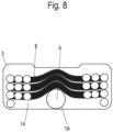
- In 8 1 is a sectional view of the drain fitting 1 looking at the drain opening 19 according to a modified embodiment of the present invention.
- the feed line 6 is designed as a triple helix. Each helix is guided with a respectively smaller winding radius within the respectively larger helix in the respective opposite vertical direction with a bend upwards over the outflow opening 19 .
- the inlet line 6 is bent upwards around the outlet opening 19 at all turns.
- the vertical distance between the turns arranged one above the other above the drain opening 19 can be reduced in order to ensure a compact structure.
- This curved arrangement of the windings enables the drain 9 to be cleaned more easily, since the drain opening 19 is freely accessible and is preferably covered by less than 20% by a winding of the inlet line 6 in plan view.
- the installation device includes the waste fitting 1, which is connected to the sanitary tub 2.
- a mixing valve 15 is connected to a hot water line 16 .
- a cold water line 17 which is connected to the mixing valve 15 and the input 7 of the inlet line 6 .
- the outlet 8 of the feed line 6 is connected to the mixing fitting 15 via the connecting line 18 .
- heated water flowing onto the sanitary tub 2 can be introduced from the mixing fitting 15 into the drain fitting 1 in order to then heat the inlet line 6 there.
- the preheated water from the inlet line 6 can then be fed to the mixing fitting 15 via the connecting line 18 .
- the drain fitting 1 can also be bypassed if water is drawn directly from the cold water line 17, for example because no hot water is added to the mixing fitting 15.
Landscapes
- Engineering & Computer Science (AREA)
- Health & Medical Sciences (AREA)
- Life Sciences & Earth Sciences (AREA)
- Hydrology & Water Resources (AREA)
- Public Health (AREA)
- Water Supply & Treatment (AREA)
- Environmental & Geological Engineering (AREA)
- Physics & Mathematics (AREA)
- Thermal Sciences (AREA)
- Chemical & Material Sciences (AREA)
- Combustion & Propulsion (AREA)
- Mechanical Engineering (AREA)
- General Engineering & Computer Science (AREA)
- Heat-Exchange Devices With Radiators And Conduit Assemblies (AREA)
- Sink And Installation For Waste Water (AREA)
Applications Claiming Priority (1)
| Application Number | Priority Date | Filing Date | Title |
|---|---|---|---|
| DE102022103889.0A DE102022103889A1 (de) | 2022-02-18 | 2022-02-18 | Ablaufgarnitur für eine Sanitärwanne |
Publications (1)
| Publication Number | Publication Date |
|---|---|
| EP4230813A1 true EP4230813A1 (fr) | 2023-08-23 |
Family
ID=85150313
Family Applications (1)
| Application Number | Title | Priority Date | Filing Date |
|---|---|---|---|
| EP23154216.8A Pending EP4230813A1 (fr) | 2022-02-18 | 2023-01-31 | Garniture d'écoulement avec récupération de chaleur pour une baignoire sanitaire |
Country Status (2)
| Country | Link |
|---|---|
| EP (1) | EP4230813A1 (fr) |
| DE (1) | DE102022103889A1 (fr) |
Citations (3)
| Publication number | Priority date | Publication date | Assignee | Title |
|---|---|---|---|---|
| DE2743333A1 (de) * | 1977-09-27 | 1979-03-29 | Brunsemann Karl Ernst | Vorrichtung zur rueckgewinnung von waermeenergie aus dem abwasser von waschbecken, spuelbecken, bidets, duschen und anderen sanitaeren einrichtungen |
| US4372372A (en) * | 1981-01-26 | 1983-02-08 | Raymond Hunter | Shower bath economizer |
| EP3372939A2 (fr) | 2014-01-17 | 2018-09-12 | Joulia AG | Échangeur thermique pour une douche ou une baignoire |
-
2022
- 2022-02-18 DE DE102022103889.0A patent/DE102022103889A1/de active Pending
-
2023
- 2023-01-31 EP EP23154216.8A patent/EP4230813A1/fr active Pending
Patent Citations (3)
| Publication number | Priority date | Publication date | Assignee | Title |
|---|---|---|---|---|
| DE2743333A1 (de) * | 1977-09-27 | 1979-03-29 | Brunsemann Karl Ernst | Vorrichtung zur rueckgewinnung von waermeenergie aus dem abwasser von waschbecken, spuelbecken, bidets, duschen und anderen sanitaeren einrichtungen |
| US4372372A (en) * | 1981-01-26 | 1983-02-08 | Raymond Hunter | Shower bath economizer |
| EP3372939A2 (fr) | 2014-01-17 | 2018-09-12 | Joulia AG | Échangeur thermique pour une douche ou une baignoire |
Also Published As
| Publication number | Publication date |
|---|---|
| DE102022103889A1 (de) | 2023-08-24 |
Similar Documents
| Publication | Publication Date | Title |
|---|---|---|
| DE202016106313U1 (de) | Wassersystem mit einem Durchflusserwärmer und einer Spülstation | |
| EP4230813A1 (fr) | Garniture d'écoulement avec récupération de chaleur pour une baignoire sanitaire | |
| DE102018112362A1 (de) | Vorrichtung und Verfahren zur Reinigung einer Trinkwasseraufbereitungsanlage | |
| EP3567170B1 (fr) | Dispositif d'évacuation pour une douche ou une baignoire | |
| DE19846515C2 (de) | Wasserinstallation mit einer Verbrauchsstelle und einem Wärmetauscher zur Vorwärmung des zufließenden Wassers | |
| DE102022109937A1 (de) | Ablaufgarnitur mit Wärmetauscher | |
| DE102015010472A1 (de) | Duschanordnung | |
| EP4306728A1 (fr) | Installation de cuvette sanitaire et dispositif d'installation | |
| WO2010111998A2 (fr) | Conduite d'eaux usées comportant un dispositif de guidage d'eau fraîche et échangeur de chaleur | |
| AT507426A4 (de) | Montageblock für den anschluss von geräten | |
| DE3045740A1 (de) | Vorrichtung zum rueckgewinnen von waerme an einem geruchsverschluss einer abwasserleitung | |
| EP4116629A1 (fr) | Dispositif et procédé de récupération de chaleur de l'eau industrielle | |
| DE3840534C2 (de) | Duschanlage | |
| EP3061877B1 (fr) | Robinetterie comprenant un raccord de tuyau fixe a l'aide d'une pince | |
| DE3246586A1 (de) | Verfahren und vorrichtung zur rueckgewinnung der in abwaessern enthaltenen waerme | |
| DE60114615T2 (de) | Heizeinheit für wärmetransportflüssigkeit für eine zentralheizungsanlage | |
| DE8203297U1 (de) | Geruchsverschluss | |
| DE102007063111A1 (de) | Verfahren zur Rückgewinnung der Abwasserwärme von Duschen | |
| AT501333B1 (de) | Brunnenstube | |
| AT507233B1 (de) | Verfahren zur nutzung der abwärme insbesondere häuslicher abwässer | |
| DE202019001248U1 (de) | Vorrichtung zur Druckentlastung eines Wassersystems und Anschlussmodul mit einer solchen Vorrichtung | |
| DE10107671A1 (de) | Absicherung gegen Rücksaugen von Unterniveau-Badewannen-Mischwasserzuflüssen mittels eines in horizontale Drehgriffe auf dem oberen Wannenrand integrierten miniaturisierten Hydraulischen-Drei-Kammer-Systemtrenngerätes | |
| DE3315219A1 (de) | Mit fernwaerme als heizmedium betreibbarer vorratswasserheizer | |
| WO2020178174A1 (fr) | Filtre comportant une périphérie variable destiné à une vanne thermostatique | |
| DE3818273A1 (de) | Badeabwasserauffangbehaelter zur waermerueckgewinnung aus warmem bade- und duschabwasser |
Legal Events
| Date | Code | Title | Description |
|---|---|---|---|
| PUAI | Public reference made under article 153(3) epc to a published international application that has entered the european phase |
Free format text: ORIGINAL CODE: 0009012 |
|
| STAA | Information on the status of an ep patent application or granted ep patent |
Free format text: STATUS: THE APPLICATION HAS BEEN PUBLISHED |
|
| AK | Designated contracting states |
Kind code of ref document: A1 Designated state(s): AL AT BE BG CH CY CZ DE DK EE ES FI FR GB GR HR HU IE IS IT LI LT LU LV MC ME MK MT NL NO PL PT RO RS SE SI SK SM TR |
|
| STAA | Information on the status of an ep patent application or granted ep patent |
Free format text: STATUS: REQUEST FOR EXAMINATION WAS MADE |
|
| 17P | Request for examination filed |
Effective date: 20231116 |
|
| RBV | Designated contracting states (corrected) |
Designated state(s): AL AT BE BG CH CY CZ DE DK EE ES FI FR GB GR HR HU IE IS IT LI LT LU LV MC ME MK MT NL NO PL PT RO RS SE SI SK SM TR |