EP3372939A2 - Échangeur thermique pour une douche ou une baignoire - Google Patents
Échangeur thermique pour une douche ou une baignoire Download PDFInfo
- Publication number
- EP3372939A2 EP3372939A2 EP18169632.9A EP18169632A EP3372939A2 EP 3372939 A2 EP3372939 A2 EP 3372939A2 EP 18169632 A EP18169632 A EP 18169632A EP 3372939 A2 EP3372939 A2 EP 3372939A2
- Authority
- EP
- European Patent Office
- Prior art keywords
- heat exchanger
- drain pan
- unit
- fresh water
- connection
- Prior art date
- Legal status (The legal status is an assumption and is not a legal conclusion. Google has not performed a legal analysis and makes no representation as to the accuracy of the status listed.)
- Withdrawn
Links
- 239000013505 freshwater Substances 0.000 claims abstract description 122
- XLYOFNOQVPJJNP-UHFFFAOYSA-N water Substances O XLYOFNOQVPJJNP-UHFFFAOYSA-N 0.000 claims abstract description 65
- 238000009434 installation Methods 0.000 claims abstract description 12
- 239000002351 wastewater Substances 0.000 claims description 100
- 238000009826 distribution Methods 0.000 claims description 84
- 238000000926 separation method Methods 0.000 claims description 24
- 239000007788 liquid Substances 0.000 claims description 13
- 238000010438 heat treatment Methods 0.000 claims description 8
- 239000010865 sewage Substances 0.000 claims description 6
- 238000010792 warming Methods 0.000 claims description 4
- 238000003860 storage Methods 0.000 description 66
- 238000007789 sealing Methods 0.000 description 45
- 238000004140 cleaning Methods 0.000 description 19
- 239000011324 bead Substances 0.000 description 13
- 239000000463 material Substances 0.000 description 13
- 239000004033 plastic Substances 0.000 description 10
- 229920003023 plastic Polymers 0.000 description 10
- 239000003570 air Substances 0.000 description 9
- 230000007704 transition Effects 0.000 description 8
- 239000002184 metal Substances 0.000 description 7
- 238000005452 bending Methods 0.000 description 6
- 230000015572 biosynthetic process Effects 0.000 description 6
- 238000005755 formation reaction Methods 0.000 description 6
- 238000000034 method Methods 0.000 description 6
- 229920001296 polysiloxane Polymers 0.000 description 6
- 239000003599 detergent Substances 0.000 description 5
- 239000006260 foam Substances 0.000 description 5
- 239000007789 gas Substances 0.000 description 5
- 150000001875 compounds Chemical class 0.000 description 4
- 238000003825 pressing Methods 0.000 description 4
- 230000008569 process Effects 0.000 description 4
- 239000012459 cleaning agent Substances 0.000 description 3
- 238000007599 discharging Methods 0.000 description 3
- 239000012530 fluid Substances 0.000 description 3
- 230000006870 function Effects 0.000 description 3
- 238000007689 inspection Methods 0.000 description 3
- 230000000284 resting effect Effects 0.000 description 3
- 238000012546 transfer Methods 0.000 description 3
- 240000003517 Elaeocarpus dentatus Species 0.000 description 2
- 241001295925 Gegenes Species 0.000 description 2
- 206010053648 Vascular occlusion Diseases 0.000 description 2
- 238000010521 absorption reaction Methods 0.000 description 2
- 238000005266 casting Methods 0.000 description 2
- 238000004891 communication Methods 0.000 description 2
- 238000010276 construction Methods 0.000 description 2
- 238000013461 design Methods 0.000 description 2
- 229920001971 elastomer Polymers 0.000 description 2
- 230000010354 integration Effects 0.000 description 2
- 230000007246 mechanism Effects 0.000 description 2
- 238000005192 partition Methods 0.000 description 2
- 229920002635 polyurethane Polymers 0.000 description 2
- 230000000717 retained effect Effects 0.000 description 2
- 239000002699 waste material Substances 0.000 description 2
- 241000272525 Anas platyrhynchos Species 0.000 description 1
- 241000589248 Legionella Species 0.000 description 1
- 208000007764 Legionnaires' Disease Diseases 0.000 description 1
- 244000089486 Phragmites australis subsp australis Species 0.000 description 1
- 208000012886 Vertigo Diseases 0.000 description 1
- 230000009471 action Effects 0.000 description 1
- 239000012080 ambient air Substances 0.000 description 1
- 230000004888 barrier function Effects 0.000 description 1
- 230000008901 benefit Effects 0.000 description 1
- 230000008859 change Effects 0.000 description 1
- 239000003795 chemical substances by application Substances 0.000 description 1
- 230000008878 coupling Effects 0.000 description 1
- 238000010168 coupling process Methods 0.000 description 1
- 238000005859 coupling reaction Methods 0.000 description 1
- 230000001419 dependent effect Effects 0.000 description 1
- 238000001514 detection method Methods 0.000 description 1
- 239000003651 drinking water Substances 0.000 description 1
- 235000020188 drinking water Nutrition 0.000 description 1
- 238000005108 dry cleaning Methods 0.000 description 1
- 239000000428 dust Substances 0.000 description 1
- 230000003670 easy-to-clean Effects 0.000 description 1
- 239000000806 elastomer Substances 0.000 description 1
- 239000011552 falling film Substances 0.000 description 1
- 239000010408 film Substances 0.000 description 1
- 238000007667 floating Methods 0.000 description 1
- 239000011521 glass Substances 0.000 description 1
- 239000008187 granular material Substances 0.000 description 1
- 239000012535 impurity Substances 0.000 description 1
- 238000007373 indentation Methods 0.000 description 1
- 230000003993 interaction Effects 0.000 description 1
- 238000010409 ironing Methods 0.000 description 1
- 238000003698 laser cutting Methods 0.000 description 1
- 238000012423 maintenance Methods 0.000 description 1
- 238000004519 manufacturing process Methods 0.000 description 1
- 239000012528 membrane Substances 0.000 description 1
- 238000003801 milling Methods 0.000 description 1
- 239000000203 mixture Substances 0.000 description 1
- 244000052769 pathogen Species 0.000 description 1
- 230000000149 penetrating effect Effects 0.000 description 1
- 230000002093 peripheral effect Effects 0.000 description 1
- 229920000642 polymer Polymers 0.000 description 1
- 239000004814 polyurethane Substances 0.000 description 1
- 230000009467 reduction Effects 0.000 description 1
- 239000000565 sealant Substances 0.000 description 1
- 125000006850 spacer group Chemical group 0.000 description 1
- 238000005507 spraying Methods 0.000 description 1
- 239000008400 supply water Substances 0.000 description 1
- 239000012780 transparent material Substances 0.000 description 1
- 230000000007 visual effect Effects 0.000 description 1
- 238000003466 welding Methods 0.000 description 1
Images


Classifications
-
- F—MECHANICAL ENGINEERING; LIGHTING; HEATING; WEAPONS; BLASTING
- F28—HEAT EXCHANGE IN GENERAL
- F28D—HEAT-EXCHANGE APPARATUS, NOT PROVIDED FOR IN ANOTHER SUBCLASS, IN WHICH THE HEAT-EXCHANGE MEDIA DO NOT COME INTO DIRECT CONTACT
- F28D21/00—Heat-exchange apparatus not covered by any of the groups F28D1/00 - F28D20/00
- F28D21/0001—Recuperative heat exchangers
- F28D21/0012—Recuperative heat exchangers the heat being recuperated from waste water or from condensates
-
- F—MECHANICAL ENGINEERING; LIGHTING; HEATING; WEAPONS; BLASTING
- F28—HEAT EXCHANGE IN GENERAL
- F28F—DETAILS OF HEAT-EXCHANGE AND HEAT-TRANSFER APPARATUS, OF GENERAL APPLICATION
- F28F1/00—Tubular elements; Assemblies of tubular elements
- F28F1/02—Tubular elements of cross-section which is non-circular
-
- F—MECHANICAL ENGINEERING; LIGHTING; HEATING; WEAPONS; BLASTING
- F24—HEATING; RANGES; VENTILATING
- F24D—DOMESTIC- OR SPACE-HEATING SYSTEMS, e.g. CENTRAL HEATING SYSTEMS; DOMESTIC HOT-WATER SUPPLY SYSTEMS; ELEMENTS OR COMPONENTS THEREFOR
- F24D17/00—Domestic hot-water supply systems
- F24D17/0005—Domestic hot-water supply systems using recuperation of waste heat
-
- F—MECHANICAL ENGINEERING; LIGHTING; HEATING; WEAPONS; BLASTING
- F28—HEAT EXCHANGE IN GENERAL
- F28D—HEAT-EXCHANGE APPARATUS, NOT PROVIDED FOR IN ANOTHER SUBCLASS, IN WHICH THE HEAT-EXCHANGE MEDIA DO NOT COME INTO DIRECT CONTACT
- F28D1/00—Heat-exchange apparatus having stationary conduit assemblies for one heat-exchange medium only, the media being in contact with different sides of the conduit wall, in which the other heat-exchange medium is a large body of fluid, e.g. domestic or motor car radiators
- F28D1/02—Heat-exchange apparatus having stationary conduit assemblies for one heat-exchange medium only, the media being in contact with different sides of the conduit wall, in which the other heat-exchange medium is a large body of fluid, e.g. domestic or motor car radiators with heat-exchange conduits immersed in the body of fluid
- F28D1/0206—Heat exchangers immersed in a large body of liquid
- F28D1/0213—Heat exchangers immersed in a large body of liquid for heating or cooling a liquid in a tank
-
- F—MECHANICAL ENGINEERING; LIGHTING; HEATING; WEAPONS; BLASTING
- F28—HEAT EXCHANGE IN GENERAL
- F28D—HEAT-EXCHANGE APPARATUS, NOT PROVIDED FOR IN ANOTHER SUBCLASS, IN WHICH THE HEAT-EXCHANGE MEDIA DO NOT COME INTO DIRECT CONTACT
- F28D1/00—Heat-exchange apparatus having stationary conduit assemblies for one heat-exchange medium only, the media being in contact with different sides of the conduit wall, in which the other heat-exchange medium is a large body of fluid, e.g. domestic or motor car radiators
- F28D1/02—Heat-exchange apparatus having stationary conduit assemblies for one heat-exchange medium only, the media being in contact with different sides of the conduit wall, in which the other heat-exchange medium is a large body of fluid, e.g. domestic or motor car radiators with heat-exchange conduits immersed in the body of fluid
- F28D1/04—Heat-exchange apparatus having stationary conduit assemblies for one heat-exchange medium only, the media being in contact with different sides of the conduit wall, in which the other heat-exchange medium is a large body of fluid, e.g. domestic or motor car radiators with heat-exchange conduits immersed in the body of fluid with tubular conduits
- F28D1/047—Heat-exchange apparatus having stationary conduit assemblies for one heat-exchange medium only, the media being in contact with different sides of the conduit wall, in which the other heat-exchange medium is a large body of fluid, e.g. domestic or motor car radiators with heat-exchange conduits immersed in the body of fluid with tubular conduits the conduits being bent, e.g. in a serpentine or zig-zag
- F28D1/0477—Heat-exchange apparatus having stationary conduit assemblies for one heat-exchange medium only, the media being in contact with different sides of the conduit wall, in which the other heat-exchange medium is a large body of fluid, e.g. domestic or motor car radiators with heat-exchange conduits immersed in the body of fluid with tubular conduits the conduits being bent, e.g. in a serpentine or zig-zag the conduits being bent in a serpentine or zig-zag
-
- F—MECHANICAL ENGINEERING; LIGHTING; HEATING; WEAPONS; BLASTING
- F28—HEAT EXCHANGE IN GENERAL
- F28D—HEAT-EXCHANGE APPARATUS, NOT PROVIDED FOR IN ANOTHER SUBCLASS, IN WHICH THE HEAT-EXCHANGE MEDIA DO NOT COME INTO DIRECT CONTACT
- F28D3/00—Heat-exchange apparatus having stationary conduit assemblies for one heat-exchange medium only, the media being in contact with different sides of the conduit wall, in which the other heat-exchange medium flows in a continuous film, or trickles freely, over the conduits
- F28D3/02—Heat-exchange apparatus having stationary conduit assemblies for one heat-exchange medium only, the media being in contact with different sides of the conduit wall, in which the other heat-exchange medium flows in a continuous film, or trickles freely, over the conduits with tubular conduits
-
- F—MECHANICAL ENGINEERING; LIGHTING; HEATING; WEAPONS; BLASTING
- F28—HEAT EXCHANGE IN GENERAL
- F28D—HEAT-EXCHANGE APPARATUS, NOT PROVIDED FOR IN ANOTHER SUBCLASS, IN WHICH THE HEAT-EXCHANGE MEDIA DO NOT COME INTO DIRECT CONTACT
- F28D3/00—Heat-exchange apparatus having stationary conduit assemblies for one heat-exchange medium only, the media being in contact with different sides of the conduit wall, in which the other heat-exchange medium flows in a continuous film, or trickles freely, over the conduits
- F28D3/04—Distributing arrangements
-
- F—MECHANICAL ENGINEERING; LIGHTING; HEATING; WEAPONS; BLASTING
- F28—HEAT EXCHANGE IN GENERAL
- F28F—DETAILS OF HEAT-EXCHANGE AND HEAT-TRANSFER APPARATUS, OF GENERAL APPLICATION
- F28F1/00—Tubular elements; Assemblies of tubular elements
- F28F1/003—Multiple wall conduits, e.g. for leak detection
-
- F—MECHANICAL ENGINEERING; LIGHTING; HEATING; WEAPONS; BLASTING
- F28—HEAT EXCHANGE IN GENERAL
- F28F—DETAILS OF HEAT-EXCHANGE AND HEAT-TRANSFER APPARATUS, OF GENERAL APPLICATION
- F28F27/00—Control arrangements or safety devices specially adapted for heat-exchange or heat-transfer apparatus
- F28F27/02—Control arrangements or safety devices specially adapted for heat-exchange or heat-transfer apparatus for controlling the distribution of heat-exchange media between different channels
-
- F—MECHANICAL ENGINEERING; LIGHTING; HEATING; WEAPONS; BLASTING
- F28—HEAT EXCHANGE IN GENERAL
- F28F—DETAILS OF HEAT-EXCHANGE AND HEAT-TRANSFER APPARATUS, OF GENERAL APPLICATION
- F28F9/00—Casings; Header boxes; Auxiliary supports for elements; Auxiliary members within casings
- F28F9/26—Arrangements for connecting different sections of heat-exchange elements, e.g. of radiators
-
- E—FIXED CONSTRUCTIONS
- E03—WATER SUPPLY; SEWERAGE
- E03C—DOMESTIC PLUMBING INSTALLATIONS FOR FRESH WATER OR WASTE WATER; SINKS
- E03C1/00—Domestic plumbing installations for fresh water or waste water; Sinks
- E03C2001/005—Installations allowing recovery of heat from waste water for warming up fresh water
-
- F—MECHANICAL ENGINEERING; LIGHTING; HEATING; WEAPONS; BLASTING
- F24—HEATING; RANGES; VENTILATING
- F24D—DOMESTIC- OR SPACE-HEATING SYSTEMS, e.g. CENTRAL HEATING SYSTEMS; DOMESTIC HOT-WATER SUPPLY SYSTEMS; ELEMENTS OR COMPONENTS THEREFOR
- F24D2200/00—Heat sources or energy sources
- F24D2200/16—Waste heat
- F24D2200/20—Sewage water
-
- F—MECHANICAL ENGINEERING; LIGHTING; HEATING; WEAPONS; BLASTING
- F24—HEATING; RANGES; VENTILATING
- F24D—DOMESTIC- OR SPACE-HEATING SYSTEMS, e.g. CENTRAL HEATING SYSTEMS; DOMESTIC HOT-WATER SUPPLY SYSTEMS; ELEMENTS OR COMPONENTS THEREFOR
- F24D2220/00—Components of central heating installations excluding heat sources
- F24D2220/04—Sensors
- F24D2220/044—Flow sensors
-
- F—MECHANICAL ENGINEERING; LIGHTING; HEATING; WEAPONS; BLASTING
- F28—HEAT EXCHANGE IN GENERAL
- F28D—HEAT-EXCHANGE APPARATUS, NOT PROVIDED FOR IN ANOTHER SUBCLASS, IN WHICH THE HEAT-EXCHANGE MEDIA DO NOT COME INTO DIRECT CONTACT
- F28D7/00—Heat-exchange apparatus having stationary tubular conduit assemblies for both heat-exchange media, the media being in contact with different sides of a conduit wall
- F28D7/08—Heat-exchange apparatus having stationary tubular conduit assemblies for both heat-exchange media, the media being in contact with different sides of a conduit wall the conduits being otherwise bent, e.g. in a serpentine or zig-zag
- F28D7/082—Heat-exchange apparatus having stationary tubular conduit assemblies for both heat-exchange media, the media being in contact with different sides of a conduit wall the conduits being otherwise bent, e.g. in a serpentine or zig-zag with serpentine or zig-zag configuration
- F28D7/085—Heat-exchange apparatus having stationary tubular conduit assemblies for both heat-exchange media, the media being in contact with different sides of a conduit wall the conduits being otherwise bent, e.g. in a serpentine or zig-zag with serpentine or zig-zag configuration in the form of parallel conduits coupled by bent portions
-
- F—MECHANICAL ENGINEERING; LIGHTING; HEATING; WEAPONS; BLASTING
- F28—HEAT EXCHANGE IN GENERAL
- F28F—DETAILS OF HEAT-EXCHANGE AND HEAT-TRANSFER APPARATUS, OF GENERAL APPLICATION
- F28F2230/00—Sealing means
-
- F—MECHANICAL ENGINEERING; LIGHTING; HEATING; WEAPONS; BLASTING
- F28—HEAT EXCHANGE IN GENERAL
- F28F—DETAILS OF HEAT-EXCHANGE AND HEAT-TRANSFER APPARATUS, OF GENERAL APPLICATION
- F28F2265/00—Safety or protection arrangements; Arrangements for preventing malfunction
- F28F2265/16—Safety or protection arrangements; Arrangements for preventing malfunction for preventing leakage
-
- F—MECHANICAL ENGINEERING; LIGHTING; HEATING; WEAPONS; BLASTING
- F28—HEAT EXCHANGE IN GENERAL
- F28F—DETAILS OF HEAT-EXCHANGE AND HEAT-TRANSFER APPARATUS, OF GENERAL APPLICATION
- F28F2265/00—Safety or protection arrangements; Arrangements for preventing malfunction
- F28F2265/22—Safety or protection arrangements; Arrangements for preventing malfunction for draining
-
- F—MECHANICAL ENGINEERING; LIGHTING; HEATING; WEAPONS; BLASTING
- F28—HEAT EXCHANGE IN GENERAL
- F28F—DETAILS OF HEAT-EXCHANGE AND HEAT-TRANSFER APPARATUS, OF GENERAL APPLICATION
- F28F2280/00—Mounting arrangements; Arrangements for facilitating assembling or disassembling of heat exchanger parts
- F28F2280/10—Movable elements, e.g. being pivotable
-
- Y—GENERAL TAGGING OF NEW TECHNOLOGICAL DEVELOPMENTS; GENERAL TAGGING OF CROSS-SECTIONAL TECHNOLOGIES SPANNING OVER SEVERAL SECTIONS OF THE IPC; TECHNICAL SUBJECTS COVERED BY FORMER USPC CROSS-REFERENCE ART COLLECTIONS [XRACs] AND DIGESTS
- Y02—TECHNOLOGIES OR APPLICATIONS FOR MITIGATION OR ADAPTATION AGAINST CLIMATE CHANGE
- Y02B—CLIMATE CHANGE MITIGATION TECHNOLOGIES RELATED TO BUILDINGS, e.g. HOUSING, HOUSE APPLIANCES OR RELATED END-USER APPLICATIONS
- Y02B30/00—Energy efficient heating, ventilation or air conditioning [HVAC]
- Y02B30/18—Domestic hot-water supply systems using recuperated or waste heat
-
- Y—GENERAL TAGGING OF NEW TECHNOLOGICAL DEVELOPMENTS; GENERAL TAGGING OF CROSS-SECTIONAL TECHNOLOGIES SPANNING OVER SEVERAL SECTIONS OF THE IPC; TECHNICAL SUBJECTS COVERED BY FORMER USPC CROSS-REFERENCE ART COLLECTIONS [XRACs] AND DIGESTS
- Y02—TECHNOLOGIES OR APPLICATIONS FOR MITIGATION OR ADAPTATION AGAINST CLIMATE CHANGE
- Y02B—CLIMATE CHANGE MITIGATION TECHNOLOGIES RELATED TO BUILDINGS, e.g. HOUSING, HOUSE APPLIANCES OR RELATED END-USER APPLICATIONS
- Y02B30/00—Energy efficient heating, ventilation or air conditioning [HVAC]
- Y02B30/56—Heat recovery units
Definitions
- the invention relates to the field of heat exchangers and more particularly to a heat exchanger for a shower or a bathtub according to the preamble of claim 1.
- EP 2273223 A1 shows a heat exchanger, which is mounted as a drain of a shower tray and is arranged elongated along one side of the shower tray. Outflowing water flows through a siphon and then substantially vertically downwards along a flat plate of a heat exchanger. Lines for fresh water are connected to this plate, for example, with webs to create a gap in which flows in the event of a leak sewage or fresh water and thus the leak is detectable.
- the bars have a maximum width of 2 millimeters. Runoff flows first through an elongated siphon and then over a diverter that distributes the water along the heat exchanger.
- the siphon is arranged in a space between two heat exchangers.
- the distribution plate may be formed integrally with a wall of the siphon.
- EP 2453194 A1 discloses a heat exchanger for a drain of a shower tray, in which the draining water is passed over elongated turns of a pipe with fresh water. Seen from above, the turns lie on loops with straight sections connected by semicircular sections. Outflowing water first flows through an elongated one Siphon and then a perforated plate, which distributes the water above the turns on this. The siphon is arranged in a space between the turns. The distribution plate is formed integrally with a wall of the siphon.
- FR 2868796 A1 shows a heat exchanger with a siphon, which is arranged in the middle of a spiral-shaped heat exchanger tube.
- the heat exchanger itself is arranged in a container acting as a siphon.
- the heat exchanger tube is located in the effluent water.
- Another possible object of the invention is to provide a heat exchanger which is easy to control, maintain and / or clean or descale.
- Another possible object of the invention is to provide a heat exchanger which is easy to assemble and / or can be used in a variety of ways.
- Another possible object of the invention is to provide a heat exchanger which has a high security with regard to leakage and building damage by leaking.
- Another possible object of the invention is to provide a heat exchanger which has a low overall height.
- Another possible object of the invention is to provide a heat exchanger that supports a hygienic operation of a shower.
- Heat exchanger for heating fresh water by means of heat from waste water in a shower or bathtub comprising a drain pan, at least one arranged in the drain pan and provided for connection to a fresh water supply heat exchanger unit, and a distribution element, which distributes effluent effluent through the at least one heat exchanger unit is arranged.
- the at least one heat exchanger unit a plurality of sequentially successive (ie, successively flowed through) pipe sections, which are interconnected by flowed deflection sections and extend substantially horizontally in an orientation of the heat exchanger as in operation of the heat exchanger.
- two horizontally extending, successive, ie interconnected only by a deflection section, pipe sections are arranged one above the other and are sequentially dripped or flooded by herabtropfendem or herab secureddem wastewater.
- a first pipe section leads in a first direction, and after a deflection section it leads a second pipe section below the first one Pipe section in the opposite direction. It is thus, along the heat exchanger tubes (respectively along the flow through the tubes) seen between the first and the second pipe section no further horizontally extending pipe section. Seen in the vertical (along the flow over the tubes), the two described pipe sections are usually also consecutive. Alternatively, however, a different sequence can also be realized in the vertical, for example by arranging a third tube section, which follows the second tube section along the tubes, in the vertical direction between the first and the second tube section.
- tubes of a heat exchanger unit are arranged one above the other, they are successively overflowed or drizzled (depending on the volume flow of the waste water) from the dripping or run-off wastewater. This can also be referred to as a falling film. It takes place between two superimposed pipe sections a new mixing in the wastewater, whereby the heat transfer to the pipes is improved.
- indications such as “horizontal” and “vertical” refer to the orientation of the heat exchanger in a built-in and operational state.
- successive pipe sections of a heat exchanger unit are arranged vertically one above the other and extend the pipe sections at least approximately horizontally.
- heat exchanger unit denotes a series of fresh water lines leading from a fresh water supply to a Frischwasserweg entry the heat exchanger and is flowed through by fresh water sequentially. There may be several heat exchanger units connected in parallel.
- the pipe sections are arranged vertically one above the other.
- the pipe sections are substantially straight.
- all the straight pipe sections of a heat exchanger unit extend in the same vertical plane.
- a second heat exchanger unit may be arranged substantially parallel thereto in another vertical plane.
- Such an arrangement is to be distinguished from a single heat exchanger unit whose straight pipe sections run in two or more vertical planes, for example with deflecting sections, which lead the pipe or the fresh water flow from one of these two planes to the other.
- connection points and / or a double separation in the drain pan can also be realized if the pipe sections run differently than described above.
- connection points can be separation points which allow mounting and dismounting, in particular without tools, ie purely manually, the at least one heat exchanger unit.
- a connection point for example, have a holding element, such as a manually operable bracket or a retaining ring with bayonet lock, etc.
- a manually detachable with a tool and restore reproducible connection for example with one or more screws.
- connection points can be movable connections, for example pivoting elements or flexible (hose) connections, which pivot out or removing the at least one heat exchanger unit from the drain pan allow. This can be done without interruption of the fresh water flow through the heat exchanger.
- the pivoting elements can, according to the other elements of the heat exchanger, be single-walled or double-walled.
- connection points can also be realized if the pipe sections run differently than described above.
- mountable heat exchanger units and / or connecting pieces can also be realized if the pipe sections run differently than described above.
- the drain pan itself may be shaped substantially symmetrical, but with a laterally led out drain or drain pipe. Then, when installing the drain pan, for example, in a shower, the drain pan can be mounted either in one of two by 180 ° about a vertical axis against each other rotated positions. This makes it possible to adapt the orientation of the drain outlet to the local conditions.
- the orientation of the connecting piece is also adaptable to the local conditions as described above.
- the heat exchanger unit itself can also be mounted in two orientations, the supply and discharge of the fresh water can be connected to the drain pan at will.
- the heat exchanger unit (s) or of fittings that lead within the drain pan to the / the heat exchanger unit (s) can then be chosen according to their orientation. This simplifies the installation greatly, and there can be no errors due to a twisted installation of the drain pan. Errors in the twisted installation of a heat exchanger unit are easily correctable.
- Heat exchanger for heating fresh water by means of heat from waste water in a shower or bathtub comprising a drain pan, at least one arranged in the drain pan and provided for connection to a fresh water supply heat exchanger unit, and a distribution element, which distributes effluent effluent through the at least one heat exchanger unit is arranged, wherein the at least one heat exchanger unit has a plurality of sequentially successive pipe sections, which are connected to one another by deflection sections, and wherein in the drain pan, an inlet area, a siphon area and a drain area are arranged, which are flowed through during operation of the heat exchanger in succession and in this order of waste water, wherein the inlet area is in air exchange with the environment above the heat exchanger, the drainage area is in the air exchange with a discharge spigot, which is intended for connection to a sewage system, and the
- the siphon area (viewed along a horizontal direction) is disposed on a first side of the heat exchanger unit, and the drain area is disposed on a second, first opposing side of the heat exchanger unit. This is a space-saving and material-saving siphon realized.
- the fresh water supply and a fresh water discharge of the heat exchanger unit is guided through a tub wall on the second side of the heat exchanger unit. This is a heat exchanger with low height realized.
- the fresh water supply and the fresh water discharge are guided by detachable pipe connections arranged within the drain pan and, in particular, these pipe connections can be produced or interrupted by a horizontal movement of the heat exchanger unit.
- the heat exchanger unit is removable by a horizontal movement and removable by a subsequent vertical movement of the drain pan.
- the fresh water supply and the fresh water discharge are arranged by releasable within disposed within the drain pan Passed pipe connections and these pipe connections by a vertical movement of the heat exchanger unit can be produced or interrupted.
- the heat exchanger unit can be removed by a vertical movement and removed from the drain pan.
- Connecting pieces for connecting the connecting pieces can be guided through the tank bottom, or led through a tank wall and then be angled upwards, so that the fittings can be inserted from above into the connecting piece respectively removable.
- the fresh water supply and the fresh water discharge are guided by detachable pipe connections arranged within the drain pan and, in particular, these pipe connections can be produced or interrupted by a diagonal movement of the heat exchanger unit.
- a movement direction for interrupting or producing the pipe connections runs at an angle of between 30 ° and 60 °, and in particular of approximately 45 ° to the horizontal (in a built-in state of the heat exchanger).
- the pipe sections of the heat exchanger unit form precisely one set of pipe sections arranged one above the other, which are successively drizzled or overflowed by dripping or running-down waste water.
- the horizontal space-saving heat exchanger unit can be realized.
- the pipe sections are arranged one above the other and offset from one another in the horizontal direction. They can be viewed in succession along a vertical direction. For example, there is a first series of pipe sections lying substantially vertically above one another and a second series of pipe sections lying substantially vertically above one another, wherein the first and the second row are offset from one another in the horizontal direction.
- the siphon area is sealed off from the drainage area by a seal arranged between the tank bottom and the damming element. This seal prevents liquid from draining from the siphon area into the drain area.
- the inlet region is sealed off from the drainage area by a seal arranged between the tank wall and a storage cover, wherein the storage cover prevents air from passing from the drainage area into the inlet region.
- This seal may be integrally formed with a seal against the tub bottom. Alternatively, it may be formed as a separate seal.
- the circumferential seal extends between the storage cover and drain pan in respectively along a plane. It may be inclined relative to the horizontal, in particular by an angle between 20 ° and 80 ° and for example between 30 ° and 70 °. Alternatively, this plane of the seal can extend in the vertical direction, ie at an angle of 90 ° to the horizontal. In this case, the seal is pressed against a tub wall.
- the gasket is a multilayer foamed gasket. It has seen in cross-section at least two first sealing beads, which are spaced from each other and between which a second sealing bead extends and is supported by the first sealing beads.
- first two sealing beads which run next to one another and at a substantially constant distance from one another, are applied to a carrier object.
- the first two sealing beads are partially or fully cured.
- a further sealing bead between and / or applied to the two first sealing beads and cured.
- the first two sealing beads stabilize the further sealing bead, so that the Material of the same does not run on the carrier object during application.
- the further sealing bead is made of a different material than the first two sealing beads, in particular of a softer material in the cured state.
- a stable and yet resilient seal can be realized.
- Such a multi-layer seal can be realized completely independently of the application shown here for heat exchangers and sewage channels for other applications.
- a heat exchanger which promotes hygienic operation of a shower, having the following characteristics: Heat exchanger for heating fresh water by means of heat from waste water in a shower or bathtub, comprising a drain pan, at least one arranged in the drain pan and provided for connection to a fresh water supply heat exchanger unit, a fresh water line through the heat exchanger and before or after the heat exchanger, a drain valve is arranged in the fresh water line, which allows emptying a portion of the fresh water line in the drain pan.
- This section also includes, for example, a supply to a shower or a tap.
- the drain valve can be actuated automatically or manually. By discharging the said section of the fresh water line, standing water is prevented from being present at temperatures at which pathogens such as Legionella can multiply.
- the deflection sections are formed by curved tubes and a bending diameter in the deflection sections is greater than a vertical distance between successive tube sections.
- a deflection section extends between successive straight pipe sections at least in sections outside the plane in which the two straight pipe sections lie.
- the deflection section may extend at least in sections in a plane which lies outside the plane in which the two straight pipe sections lie.
- the deflection section extends at least in sections in a plane which is parallel to the plane in which the two straight pipe sections lie and is spaced from this plane.
- the tube in this sequence can have first, second, third and fourth tube sections, and a first deflection section between the first and the second tube section, a second deflection section between the second and third tube sections, and a third deflection section between the third section and the fourth pipe section.
- the first and the third deflection section in a projection onto the plane in which the pipe sections run, are at least partially overlapping. Because the first and the third deflection section extend at least in sections in different planes, they can be guided past each other.
- the heat exchanger unit is connected to a first connection piece for supplying fresh water and a second connection piece for discharging fresh water
- the drain pan has a first and a second connection piece, which lead into and out of the drainage tub, respectively first connection piece on the first connection piece and the second connection piece on the second connection piece detachably mounted.
- the two connecting pieces and correspondingly also the connecting pieces can both be arranged on the same side of the heat exchanger, or on opposite sides, or in an area in the middle of the heat exchanger. If they are arranged on the same side, then there is an even number of pipe sections in a heat exchanger unit. If they are arranged on opposite sides, then there is an odd number. If they are arranged in an area in the middle, then two heat exchanger units, which extend in opposite directions, can be connected to the connection pieces.
- the fittings are manual, in particular tool-free, so purely manual, mountable and disassembled.
- the connecting pieces with screws are detachably mounted on the connecting piece.
- the first connection piece has a stopcock for interrupting a fresh water supply.
- At least one of the fittings mounted on the corresponding connection piece, by means of a pivotable closure bracket.
- the lock strap can be latching.
- the closure bar can be shaped such that one or more of the elements arranged above it (distribution element and / or storage element, eg realized as a drip tray, cover or cover plate) can only be completely and correctly inserted when the closure bar is in an end position in the connected state of the corresponding connector is.
- the corresponding element for example, the distribution element or storage element, have elements which project inwardly and collide with the closure bracket, if it is not in said end position.
- At least one of the closure clips pushes the corresponding connection piece from the corresponding connection piece when opening.
- the closure clip can be mounted on the connecting piece, in particular rotatable, wherein at least one corresponding pressing element is arranged on the connecting piece.
- the pressure element is detected by the closure bracket and thus pulled the connection piece against the connection piece.
- the closure clip can also be mounted on the connecting piece, in particular rotatable, and the corresponding pressing element can correspondingly be arranged on the connecting piece. The operation when closing and opening is analog.
- the closure bar has at least one locking element which blocks or impedes an opening movement of the closure bar when a force is present between the connection piece and Connecting piece acts, which drives the two apart. This can be prevented that the shutter bracket is opened unintentionally, as long as the at least one heat exchanger unit is under pressure (of the fresh water).
- the locking element can be realized, for example, by having a contact surface of the closure strap, which is in operative connection with a corresponding pressure element, a curvature or a discontinuity or detent.
- Sensors for measuring an inlet temperature, an outlet temperature and / or a flow meter for the fresh water can be arranged at the connecting piece. Furthermore, a sensor for a waste water temperature may be present. In this way, an efficiency of the device can be determined at least approximately and transmitted or displayed to a user.
- filter elements may be arranged at the connection piece or the connecting pieces, in particular at that for the supply of fresh water.
- backflow preventer for example, one-way valves, arranged, in particular in the fresh water supply.
- At least one of the two connecting pieces in the vertical direction through a trough bottom of the drain pan and is designed as an angle, for example, at an angle of 90 ° to the horizontal connection of a fresh water supply respectively a fresh water discharge.
- connection piece rotatable or in different, each rotated by 90 ° about a vertical axis to each other positions mounted.
- orientation of the connection piece can be easily adapted to the local conditions during assembly of the heat exchanger, depending on the direction from which the lines for the fresh water are brought to the heat exchanger.
- the trough bottom has a depression, which drainage effluent to at least one outlet nozzle for connection to a sewer, and the orifices or the connecting pieces are arranged in a region adjacent to the recess.
- connection piece protrudes into the connection piece.
- this section of the connection piece can be fixed to a corresponding element inside the connection piece.
- connection between the connecting piece and connector is secured before pulling out.
- the interior of the fitting may be accessible through an opening, which may be open or closed with a transparent or non-transparent lid.
- the tray odor trap may be realized by a vertical wall portion which blocks an upper portion of the downcomer and by a subsequent portion of the downcomer has an elevation, which accumulates effluent waste water at least up to the level of a lower edge of said wall portion.
- the outlet nozzle may have a closure element or drainage barrier, with which the flow can be closed.
- a heat exchanger unit or a set of heat exchanger units is movably mounted in the drain pan and is movable out of the drain pan without interruption of the fresh water supply passing through the heat exchanger, in particular by a pivotal movement about a pivot axis.
- connection unit in particular a pivot unit with a first rotatable connection for fresh water supply to at least one heat exchanger unit and a second rotatable connection for fresh water discharge from the at least one heat exchanger unit, wherein the two rotatable connections are arranged to rotate about a common pivot axis.
- the pivot axis can be horizontal. Then, the pivotal movement of the at least one heat exchanger unit extends in a vertical plane.
- the pivot axis may be at an angle to the horizontal, for example at an angle of at least 5 °, 10 °, or 20 ° to the horizontal. Then, the pivoting movement of the at least one heat exchanger unit extends in a plane which extends at a corresponding angle to the vertical. In this way it can be avoided that the at least one heat exchanger unit collides when swinging out with permanently installed sanitary elements, for example a shower bar.
- the swing-out at least one heat exchanger unit may be mechanically coupled to a further pivotable further element, such as a cover and / or a distribution element.
- the coupling can be a scissors mechanism. It causes the heat exchanger unit is also swung out when swinging out of the other element.
- the fittings and optionally also the connecting pieces can therefore be double-walled, for example, with an inner and an outer wall, which are interconnected by webs.
- the connecting pieces can be double-walled, at least in the region which lies within the drain pan and thus can come into contact with waste water. Then, when connecting a fitting to a fitting, the interstices of the fitting are also connected to those of the fitting.
- At least one of the connecting pieces on one or more deflecting elements each corresponding to a line section with a deflection by 180 °.
- the two ends of such a line section are each connected to a pipe section.
- the deflecting elements are also double-walled, and an intermediate space of the deflecting elements is connected to the intermediate space of the double-walled pipes.
- the deflecting elements can be formed at least partially as part of the connecting pieces.
- the deflecting elements thus form deflecting sections as far as the liquid guidance of the fresh water is concerned.
- the deflecting elements are not formed as tubes but as hollow regions in the connecting piece, for example as recesses in the production of the connecting piece by casting, spraying or milling.
- the tubes are used for connection with the deflection elements in the fittings. They can be sealed with sealing rings, a sealant such as silicone or a two-component elastomer. If the pipe sections are superimposed, the deflection runs in a substantially vertical plane.
- a further alternative is to provide a connection piece with an elastic covering as outer skin, for example made of silicone, wherein a section of the outer skin is designed to seal to an inserted tube section.
- one of the connecting pieces has an envelope made of an elastic plastic, which covers at least part of the connecting piece and forms a second separation between fresh water-carrying areas and waste-water-conducting areas of the heat exchanger.
- This embodiment can also be realized if there are no deflecting elements of a deflection by 180 ° or if there are no deflecting elements. If there are no deflecting elements, the fittings are pure collectors.
- An intermediate region between the casing and the respective connection piece is connected to a space between the pipes and / or other elements, so that leakage water can flow from the intermediate space to the intermediate area and vice versa. If there is no leak water, the wrapper may be snug against the fitting. If leak water leaks, the envelope may expand due to their elasticity and absorb the leak water and continue.
- an area of the enclosure forms a sealing area between the connection piece and the drainage trough, in particular a trough wall or the trough floor.
- This sealing area thus seals the fresh water supply or the fresh water discharge with respect to the interior of the drain pan, in particular as a second separation.
- This separation can also be referred to as outer separation or outer wall - starting from fresh water area.
- a portion of the enclosure forms a sealing area between the fitting and a pipe section inserted therein.
- This sealing area thus seals a pipe section with respect to the interior of the drain pan, in particular as a second, external separation.
- the sheath abuts the outer tube of the tube section, either as a collar leading away from the fitting, following the tube section, or as a sleeve inserted into the fitting and located between the fitting and the tube section.
- a portion of the enclosure forms a sealing area between the fitting, and a closure of a viewing opening inserted into the fitting.
- This sealing region thus seals the intermediate space of the connecting piece with respect to the interior of the drain pan, as part of a second, external separation.
- the sealing area overlaps For example, the viewing port and is pressed by the inserted closure inward against the edge of the viewing port.
- a portion of the envelope forms a sealing area between the fitting and a lid resting on the fitting, in particular a jam lid, or other element, with an opening of the lid and sealing the opening with respect to a region around the fitting through this sealing area ,
- This area around the fitting is the drain area.
- this sealing area typically seals the inlet area in relation to the drainage area.
- the opening in the cover or storage cover allows, for example, a view of the enclosure or through the enclosure (if it is transparent) or through a hole in the enclosure and through a view opening arranged behind this hole in the connector.
- a material is introduced in an intermediate region between the sheath and the connecting piece, which changes color upon absorption of water and wherein the sheath is transparent or semitransparent (ie not opaque). Leakage water entering the intermediate area thus leads to a change in color which can be recognized from outside through the covering, for example through an opening in a cover or storage cover as described above.
- the deflecting elements may be formed in connecting pieces which do not also have the function of connecting pieces or collecting pieces. Such connecting pieces have only one, two or more deflecting elements and thereby connect two, four or a higher, even number of pipe sections to one another.
- a heat exchanger unit at one end may have such a connector and at the other end a connector, which has a connection of a pipe section for fresh water supply and another Pipe section for fresh water removal forms, and optionally also one or more deflecting elements.
- the pipe sections are bent, each of the pipe sections extending in an associated horizontal plane.
- one end of a bent pipe section may be arranged in the vicinity of a beginning of the same pipe section.
- a bent pipe section can thus almost form a closed loop.
- it may be formed following a circular section, for example by an angle of more than 270 °.
- Several such pipe sections are arranged one above the other, for example exactly above one another. Alternatively, they can be arranged offset from one another in the radial direction, for example by pipe sections lying one above the other following in each case circular sections with different radii.
- fittings or connectors are arranged.
- these fittings or connectors may be combined into a single part.
- Such a combined connecting piece or connecting piece thus has deflecting elements for the beginning and the end of the pipe sections.
- connecting pieces may be present, each having one or more deflection elements as deflection, wherein a deflection corresponds to a line section, which realizes a vertical offset of the line, so the two ends of such a line section are connected to pipe sections that are vertical to each other are offset and continue the line in the same direction or in the same sense of circulation.
- fittings or connectors made of plastic or metal can be cast or injected. They can be single-walled or double-walled. They may be made of only one material, or of a combination, for example, with an inner part of metal, in which the fresh water is guided, and with an outer part or a sheath, for example made of plastic, in particular silicone, which realizes the second partition.
- connection unit can also be a double-walled connection piece or connecting piece.
- Connecting elements such as webs, spacers, welding points, etc., which bridge the gap have, for example, a diameter or in at least one direction, a maximum extension of two millimeters. This corresponds to common standards for the design of heat exchangers between fresh water and wastewater.
- connection unit as a whole is pivotable with respect to the drain pan and connected to pivotal connections, and the at least one heat exchanger unit is substantially rigidly connected to the connection unit and pivotable by pivoting the connection unit from the drain pan.
- connection unit is substantially rigidly mounted in the drain pan and has single-wall freshwater lines, in particular pipes and / or flexible hoses, in particular armored hoses, in the interior, to the transition between connecting pieces and heat exchanger units, and is the at least one heat exchanger unit on the connection unit connected to a first and a second rotatable terminal, wherein the two rotatable terminals are arranged to rotate about a common pivot axis.
- the attachment unit is substantially rigidly mounted in the drain pan but has pivotal elements which are pivotally mounted relative to other elements of the attachment unit and with these other elements with elastic and liquid-tight elements, for example a bellows or membranes of rubber or other Plastic are connected liquid-tight and thereby a separation of the inner region cause the connection unit of the waste water bearing areas.
- the at least one heat exchanger unit is fastened to the pivotable elements and the connections of the heat exchanger unit lead through the pivotable elements, for example to flexible hoses, in particular hoses, in the interior of the connection unit.
- the heat exchanger has a siphon, through which wastewater passes to the distribution element, wherein the siphon surrounds the at least one heat exchanger unit.
- the siphon viewed in a horizontal sectional plane in the area of the heat exchanger unit, surrounds the at least one heat exchanger unit.
- the siphon thus runs around the at least one heat exchanger unit. Passage gases which pass through the distribution openings are retained by the siphon, in particular on all sides around the at least one heat exchange unit.
- This is in contrast to heat exchangers from the prior art, where there is only one cover between the channel gases and the environment, which consequently must rest as gas-tight as possible on its base.
- this construction allows no further siphon to be needed after the heat exchanger (for example, the above-mentioned tray odor trap), whereby the overall height of the heat exchanger can be kept low.
- the siphon may be multi-level, i. consist of several serially connected in series siphons or siphon stages.
- a legally required damming height of the siphon for example, 5 cm, so-called sealing water level
- a low overall height for example, 5 cm, so-called sealing water level
- the heat exchanger on a storage element, which surrounds the at least one heat exchanger unit, and a distribution element for Distributing wastewater over the at least one heat exchanger unit, wherein the damming element retains effluent flowing, so that it flows over the distribution element.
- the distribution element may have distribution openings. These are arranged substantially perpendicularly at least above one or more of straight pipe sections. They can also be arranged above bent pipe sections, for example if a plurality of bent pipe sections, which in each case run essentially horizontally, form a deflection arranged one above the other.
- the distribution element can be formed integrally with the storage element, for example in the form of a downwardly open elongated container with holes in the cover.
- the heat exchanger has a lid which surrounds the baffle element with a lid edge
- the lid viewed in a horizontal sectional plane in the region of the damming element, surrounds the damming element.
- Expiring water thus passes under the lid edge and through the baffle element to the distribution element and through the distribution openings.
- the damming element lies in particular with a lower edge on the trough bottom, with a peripheral seal between the damming element and the trough bottom.
- the seal can be attached to the storage element.
- the seal may be secured to the tub bottom, and the baffle member rests on the seal or is plugged into the seal.
- this has at least two heat exchanger units, wherein depending on a volume flow of the waste water, only one of the heat exchanger unit is operated or two heat exchanger units are operated.
- one of the at least two heat exchanger units is fed by a pressure-controlled valve which opens when an inlet pressure of the valve exceeds a first pressure threshold.
- the valve closes again when falling below a second pressure threshold at the input of the valve.
- the second pressure threshold may be smaller than the first one.
- the distribution element has a first and a second group of distribution openings, wherein the distribution openings of the first group are arranged above a first heat exchanger unit and already at a low volume flow of the waste water are flowed through, and the distribution openings of the second group are arranged above a second heat exchanger unit and are only flowed through when the volume flow of the waste water exceeds a threshold value.
- an overflow or dust area of the damming element leading to the distribution openings of the second group may be higher than a corresponding overflow, It may alternatively or additionally be a dividing wall or a separating web between the regions of the two groups of distribution openings, for example, the web is only flooded with wastewater when its volume flow exceeds the threshold value.
- the distribution element has at least one overflow opening, which allows waste water to drain off when the distribution openings can not discharge the wastewater.
- the overflow opening can lead the wastewater past the at least one heat exchanger unit and / or flow into the drain pan via the tubes of the heat exchanger unit.
- the heat exchanger can be arranged because of its low height in an edge region of a shower tray. However, it can not be arranged directly at the end of a shower or bath, for example, in or on a wall next to a shower or bath, or in the area of a bathtub rim.
- the heat exchanger can be supplied with wastewater from a plurality of, for example, juxtaposed showers or a shower and arranged for example next to the shower bath.
- the heat exchanger is combined with a shower partition to form a structural unit. This makes a splash-proof transition between the two reliable and easy to implement and simplifies final assembly.
- the heat exchanger has a stopper, wherein in a first position of the stopper, the stopper prevents drainage of water from the drain pan and in a second position the stopper allows drainage of water from the drain pan.
- the stopper may have an overflow opening, which allows a drainage of water in both positions when it exceeds a certain height in the drain pan.
- the heat exchanger according to the various aspects of the heat exchange between wastewater and fresh water is provided. But there are also other applications possible in which, for example, a low height with good efficiency, and / or high flexibility in the assembly and / or good maintainability and ease of cleaning and / or high security with regard to leakage are required.
- the two fluids or media between which the heat is exchanged will be referred to as waste water and fresh water, but in general also a first (heat energy emitting) medium and a second (heat energy absorbing) medium may be used
- the heat exchanger units are usually operated as a countercurrent or cross-countercurrent heat exchanger. However, operation as a DC or cross-DC heat exchanger is also possible.
- the drain pan or the heat exchanger can be arranged to receive wastewater from a shower tray or a sink or a bathtub. In principle, applications are also possible in other areas.
- FIG. 1b a single heat exchanger unit 2
- FIG. 1c two heat exchanger units 2.
- the latter are connected in parallel, which means that the flow of fresh water is split between the two heat exchanger units 2.
- the one or both heat exchanger units 2 are connected to a first connecting piece 21 and a second connecting piece 22 (connecting pieces can generally also be referred to as collecting pieces).
- the first connection piece 21 is detachably connected to a first connection piece 31.
- the second connecting piece 22 is detachably connected to a second connecting piece 32.
- the one or more heat exchanger units 2 are arranged in a drain pan 3 or simply trough, and the connecting pieces 31, 32 pass through a trough bottom 33.
- the heat exchanger unit (s) 2 are supplied with fresh water through the first connecting piece 31 and the first connecting piece 21 second connector 22 and the second port 32, the fresh water from the resp. the heat exchanger units 2 directly to a consumer, such as a shower or a faucet, or indirectly via a mixer tap, a water heater or a boiler etc. passed on.
- the first fitting 21 may include a stopcock 312.
- a temperature sensor 311, 321 for measuring the inlet temperature and the outlet temperature of the fresh water can each be arranged at the two connecting pieces 21, 22 or the connecting pieces 31, 32.
- a flow sensor 322 may be arranged to measure the volume flow of the fresh water. From the flow and the temperatures, the energy recovered in the heat exchanger can be calculated. Alternatively, one or more of these sensors may be disposed on pipe sections 24, respectively.
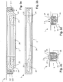
- a heat exchanger unit 2 has a plurality of, in the present embodiment, there are three, vertically stacked straight pipe sections 24 on.
- straight pipe sections 24 are the two fittings 21, 22 at opposite ends of the heat exchanger unit 2.
- the straight pipe sections 24 of a heat exchanger unit 2 are successively flowed through by the fresh water, wherein in each case between two consecutive straight pipe sections 24, a deflection section 25 is present.
- a diameter of a bend in the deflection section 25 is substantially equal to a distance of the tubes of the straight pipe sections 24.
- the tubes are double-walled, to achieve such a small deflection radius, the deflection can not be generated by bending the tubes, but by connecting the straight Pipe sections 24 with separately produced double-walled deflection tubes.
- the drain pan 3 has a trough bottom 33 with a recess 35, as well as the trough bottom 33 subsequent tub walls 34.
- the recess 35 leads wastewater to a drain pipe 36 which is provided for connection to the sewer.
- the outlet nozzle 36 may have a projecting from the top of the outlet nozzle 36 wall or drain 361, which arranged with a drain in the direction of the drain 361 increase 362nd forms another siphon or tub odor trap 37 in the process.
- a tray odor trap 37 can also be realized in all other embodiments.
- the tub bottom 33 can be considered as a shoulder. On this shoulder, so on the tub bottom 33 in an area around the recess 35 around, and in particular on a flat portion of the tub bottom 33, is located on a baffle element 4, which prevents effluent drainage to drain into the recess 35, and thereby to a Dammed up dammed. So there is only a single sealing level at the bottom of the siphon.
- the distribution element 42 has distribution openings 43 which distribute the wastewater over the at least one heat exchanger unit 2.
- the wastewater is distributed as above the straight pipe sections 24 and passed over them.
- the distribution openings 43 are a linear arrangement of holes in the distribution element 42.
- the distribution openings 43 can also be a plurality of slits arranged linearly one behind the other or a single long slit per heat exchanger unit 2.
- the distribution element 42 may be formed integrally with the storage element 4.
- the storage element 4 is a downwardly open container whose side walls accumulate the waste water, and whose upper surface acts as a distributor element 42 and is provided with the distribution openings 43.
- the lower edges of the storage element 4 may be provided with a seal 41 to seal the storage element 4 against the tub bottom 33.
- the seal 41 may be secured to the tub bottom 33 and the baffle 4 may be placed on the seal 41 or inserted into a groove in the seal 41, such as in the Figure 1d shown.
- a channel 45 in particular a channel surrounding the baffle element 4 and the heat exchanger unit 2.
- a cover 5 is arranged above the damming element 4 and the distribution element 42.
- the lid 5 is also a downwardly open container. Its side walls, also called cover wall 51 or siphon wall, protrude into the area in which the waste water is dammed up by the damming element 4. The waste water is thus forced to flow outside around the lid 5 and the lid wall 51, and then inwardly under the lid wall 51, and then up the side walls of the baffle 4 along the distribution member 42. Thereby, a siphon or trap is formed right at the beginning of the waste water flow into the heat exchanger 1 inside, and without gas-tight seals (between the channel gases and the ambient air) are required.
- the upper surface of the lid 5 may be arranged substantially flat in the plane of the bottom of a shower tray. Around the lid 5 around is formed between the lid 5 and an upper edge of the drain pan 3, a narrow drain slot 53rd
- an inlet region E , a siphon region S and a discharge region A are arranged in the drain pan 3, which are flowed through in succession and in this order of wastewater during operation of the heat exchanger 1.
- FIG. 2 shows a variant of the first embodiment.
- a cover 54 arranged on the lid 5 is wider in one or in two directions than the storage element 4 and the heat exchanger unit (s) 2.
- the drain pan 3 or a base plate surrounding the drain pan 3 has a feed area which extends around the Cover 54 around running water into the drain pan 3 and thus into the siphon leads. This makes it possible to produce a heat exchanger 1 in standard sizes and adapt with covers 54 of different sizes, the length of the drain slot formed at the edge of the cover 53 to showers of different sizes.
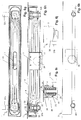
- FIGS 3a-3d show a second embodiment of a heat exchanger in various sectional views and variants.
- the deflection sections 25 have here a larger diameter than the vertical distance between the straight pipe sections 24. This makes it possible to produce the pipe sections 24 and the deflection section 25 from the same tubes. This is particularly the case when the tubes are double-walled and the minimum bending radius of these tubes is correspondingly large.
- FIGS. 3c and 3d show two of the heat exchanger units 2 according to the Figures 3a-3b parallel to each other in a drain pan.
- the tubes are compressed at least in the straight pipe sections 24 in the vertical. This gives them, for example, an oval or elliptical cross-section. Their diameter in the vertical direction is thus smaller than in the horizontal direction. Leave it to achieve a reduction in the height of the heat exchanger unit 2.
- Such compressed tubes are of course used in all other described embodiments and can be combined with their features.
- FIGS. 4a-4d show a third embodiment of a heat exchanger in various sectional views. Most of the elements are functionally the same as in the preceding figures, the description is therefore not repeated, but only the differences are described:
- the heat exchanger unit 2 shown has several, in the present embodiment, there are six, vertically stacked straight pipe sections 24 on , In an even number of straight pipe sections 24, the two connecting pieces 21, 22 are located at the same end of the heat exchanger unit 2.
- the deflection portions 25 have a larger diameter than the vertical distance between the straight pipe sections 24, and are single of Deflection sections 25 led out of the plane of the straight pipe sections 24.
- the FIG. 4a shows a single heat exchanger unit 2, in a variant of the embodiment, two heat exchanger units 2 are arranged parallel to each other, analogous to the embodiment of Figures 3b or 3c ,
- FIG. 4d shows in addition to the already described upset tubes 23 a mechanical tub odor trap 37. This closes the drain pipe 36 against the sewer system. It may be manually operable, or it may be mechanically coupled to the baffle element 4, so that when lifting or removing the baffle element 4 of the tub odor trap 37 is closed.
- FIG. 5a-5b show the main installation variants of heat exchangers:
- FIG. 5a schematically shows the installation already described in a gutter of a shower tray and the connection of the drain nozzle 36 to a drain pipe 363 to the sewer.
- FIG. 5b shows a combination with another drain 55, for example from a bathtub.
- the further process 55 leads from the outside the drain pan 3, specifically in its siphon area, that is to say in a region outside the damming element 4.
- the wastewater supplied by the further drain 55 is therefore also guided by the siphon onto the distributor element 42.
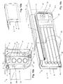
- FIGS 6a-6m show a fourth embodiment of a heat exchanger in various sections and views.
- the elements are functionally the same as in the preceding figures, the description is therefore not completely repeated, but the differences are mainly described:
- the heat exchanger 1 two parallel heat exchanger units 2, which at opposite ends to a first connector 21st and a second connector 22 are connected.
- the two connecting pieces 31, 32 are designed in two parts: in each case an upper part 31a, 32a and a lower part 31b, 32b are connected to each other, in particular releasably connected.
- the upper part 31a, 32a is located substantially within the drain pan 3 and can be double-walled
- the lower part 31b, 32b is located substantially outside the drain pan 3 and is usually not double-walled.
- the lower part 31b, 32b can be connected in different orientations to the corresponding upper part 31a, 32a, which are offset for example by 90 ° or 180 ° from each other.
- the orientation of the connections can be adapted to the circumstances during installation.
- FIGS. 6b and 6f show:
- the connecting pieces 21, 22 are detachably mounted by means of closure clips 314, 324 to the connecting piece 31, 32.
- closure clips 314, 324 To connect, for example, the first connection piece 21 with the first connection piece 31, the first closure clip 314 is pivoted to the side and the first connection piece 21 is placed on the first connection piece 31.
- the latter grasps a part (or pressure element) 315 of the first connection piece 21 with an upper control surface and presses it so that the first connecting piece 21 against the first connecting piece 31. In an end position of the locking clip 314 this preferably engages.
- the first connection piece 21 is securely pressed against the first connection piece 31 and a liquid-tight connection can be realized.
- the upper ironing surface has, as a locking element, a discontinuity or bend 315 which, when the heat exchanger unit 2 is under pressure and the first connection piece 21 is pushed upwards, impedes or blocks an opening of the closure clip 314.
- the stopcock 312 has a valve, for example a ball valve, and an actuator, here a lever.
- This shut-off lever is shaped and arranged so that the locking bar 314 is locked in its closed position as long as the stopcock 312 is open.
- the lock bracket 314 can only be opened when the shut-off lever is turned to the position in which the stopcock 312 is closed.
- FIGS. 6d and 6e show: The straight pipe sections 24 and the fittings 21, 22 are double-walled. Likewise, the connecting pieces 31, 32 are double-walled. A gap 212 of a first connecting piece 21 is connected to a gap 315 of the first connecting piece 31. To seal the fresh water line and the interstices, O-rings 213 are arranged concentrically between the first connection piece 21 and the first connection piece 31.
- the double-walled tube 23 is connected to an outer tube 23 a at an outer part 21 a of the first connector 21 and an inner tube 23 b with an inner part 21 b of the first connector 21. A gap of the tube 23 (not visible in the figure) is with the gap 212 of the first connector 21 is connected.
- the outer and inner parts 21a, 21b of the first connecting piece 21 are interconnected by webs. The webs have, for example, a thickness of less than 2 millimeters, according to legal regulations on heat exchangers in the drinking water sector.
- a viewing aperture 211 made of, for example, a clear plastic or glass provides insight into the gap 212 and allows detection of whether liquid is in the gap 212.
- the Figures 6g and 6h show in addition to the elements already described a plug 7 for selectively closing the drain or the drain neck 36 itself.
- the heat exchanger units 2 are arranged so that a gap remains between them, in which the plug 7 is arranged.
- the plug 7 is manually operable and can be in at least two different positions. In a first position, which is provided for the operation of the heat exchanger 1, the plug 7 releases the flow. In a second position, which is provided for a dry cleaning of the heat exchanger 1, the stopper 7 closes the drain.
- the drain pan 3 can be filled with water. A cleaning and / or descaling agent can be added to the water and act.
- the plug 7 may act as an overflow, i. that water, which flows over an upper edge of the plug 7, flows through the plug 7 through to the drain.
- the water flows in this case first through the overflow opening 44 of the distributor 42 and then through the plug 7.
- the plug 7 can be arranged one-way valves, such as diaphragm valves 77, which allow the drainage of water, but an increase of duct gases prevent. This is relevant only when cleaning, because in operation, the process is open anyway and the channel gases are retained by the siphon.
- the plug 7 is higher in the second position (ie, when the drain is closed) than in the first. Then, when mounting the damming element 4, respectively, of the distribution element 42, this pushes the plug 7 downwards, whereby the flow is opened. This prevents the process from being mistakenly closed. Generally speaking, therefore, when mounting the storage element 4 moves the plug 7 in an open position.
- Knurled screws serve as fasteners 56 to hold the baffle 4 downwardly against buoyancy and to provide a secure seal by means of the seal 41 with respect to the well bottom 33.
- These fastening elements can be fastened to the two connecting pieces 21, 31.
- the fasteners 56 may act against a spring or be designed so that when loosening the fasteners 56, the baffle element 4 is raised a little, for example by a few millimeters. As a result, the channel 45 is emptied and can be rinsed through for cleaning.
- the cover 5 may have one or more closable openings. Thereby, the following method for cleaning the heat exchanger unit 2 can be realized Through these openings, a detergent in foam form is injected under the baffle 4. After an exposure time, the foam is washed away together with dissolved impurities. Because it is present as a foam, the cleaning agent does not flow through the outlet pipe 36 but can act on the tubes 23 and other elements of the heat exchanger unit 2 during the entire exposure time. The method is particularly suitable for removing a biofilm.
- Distance elements or support elements 52 may support the cover 5 on the storage element 4 respectively the distribution element 42.
- FIG. 6i shows a cross-sectional view of the short side of the heat exchanger. 1
- FIGS. 6j and 6k each show a lateral view of the heat exchanger 1, visible from the outside are only the drain pan 3, the outer parts of the connecting piece and the drain pipe 36th
- Figure 6l shows a plan view of a heat exchanger 1 with removed cover. 5
- FIG. 6m shows a plan view of a heat exchanger 1 with inserted cover. 5
- FIGS. 7a-7d show a fifth embodiment of a heat exchanger in a sectional view from above ( Figure 7a ), two lateral sectional views on the longitudinal side ( FIGS. 7c and 7d ) with partially and completely swung-out heat exchanger unit 2 and a lateral sectional view on the narrow side ( FIG. 7b ).
- a heat exchanger unit 2 with a coiled tubing is rotatably arranged respectively pivotally.
- the swing mechanism is also feasible for heat exchanger units 2 or pairs of heat exchanger units 2 as in the other embodiments.
- the heat exchanger 1 has a connection unit 6, which is watertight with respect to the remaining drain pan 3.
- the fresh water supply and fresh water discharge leads from outside the drain pan 3 in the connection unit 6 and in an inner region 61 of the connection unit 6 by flexible lines 62 through two rotatable connections 63 in the heat exchanger unit 2.
- the two rotatable connections 63 are arranged to rotate about a common pivot axis 64 ,
- the tubes of the heat exchanger unit 2 may be double-walled.
- a gap 23c of the tubes (see Figures 12a and 12b ) is then in communication with the inner region 61, so that penetrating leak water enters the inner region 61 and becomes visible, for example through a control opening or a viewing window.
- the leak water may be directly visible, or it may move or move a movable indicator element, such as a float, so that in the presence of leakage water, this indicator element will be visible through the inspection port or window.
- FIG. 8 shows a multi-stage siphon. Such a multi-stage siphon can be combined with all embodiments and be realized independently in other applications.
- the lid 5 has not only one but two lid edges 51a, 51b. These are arranged one inside the other, so to speak, concentric with one another.
- the storage element 4 has at least one circumferential and upwardly open first or inner channel 45a.
- An inner lid edge 51a extends within the first groove 45a.
- An outer lid edge 51b extends outside the first groove 45a. Outgoing wastewater thus flows under the outer lid edge 51b, over the edge of the first groove 45a, under the inner lid edge 51a and over the baffle element 4.
- a seal 41 may seal the first groove 45a with respect to the drain pan 3.
- a further or outer groove 45b is thus formed between the inner groove 45a and the tub wall 34.
- the outer groove 45b be part of the storage element 4, respectively with the first groove 45a connected or shaped together.
- a seal may then also be present at the location designated 41b.
- FIG. 9a shows a cross section through a distributor element 42 with various distribution openings 43.
- a group of first distribution openings 43a is arranged above a first heat exchanger unit 2a
- a group of second distribution openings 43b is arranged above a second heat exchanger unit 2b.
- a group of third distribution openings 43c may be arranged above a third heat exchanger unit 2c.
- the first distribution openings 43a lie in depressions and are therefore flowed through in front of the second distribution openings 43b.
- the second distribution openings 43b have no or only slightly raised edge and are substantially only flowed through when the flow of waste water exceeds a first threshold and is so large that it is no longer absorbed by the first distribution openings 43a.
- the third distribution openings 43c have a raised edge, and accordingly flow through only when the wastewater flow exceeds an even higher threshold.
- the supply of the heat exchanger units is shown schematically:
- the first heat exchanger unit 2a is always flowed through, the second heat exchanger unit 2b is powered by a first pressure-controlled valve 245b and only fed when the volume flow of fresh water and thus a pressure at the inlet of the valve 245 a threshold exceeds.
- the optional third heat exchanger unit 2c is fed analogously by a second pressure-controlled valve 245c and is only supplied when the volume flow of the fresh water exceeds a further, higher threshold value.
- FIG. 9b An alternative form of the distribution openings 43 is in the FIG. 9b schematically at a section showing only the distribution element 42 shown.
- the first distribution openings 43a have no edge.
- the second distribution openings 43b have a raised edge and are therefore only flowed through when the current of the waste water is so large that it is no longer completely absorbed by the first distribution openings 43a.
- the third distribution openings 43c have a still further increased edge, and accordingly flow through only when the wastewater flow exceeds an even higher threshold.
- distribution openings may also be present, which are only flowed through at an even higher volume flow, for example with even higher edges than the second distribution openings 43b, and accordingly, a further heat exchanger unit 2 is fed by a further pressure-controlled valve, which only at a still higher pressure threshold responds.
- controlled valves for example, electric, hydraulic, mechanical, etc.
- a flow meter instead of pressure-controlled valves and a flow meter can be used, and controlled valves (for example, electric, hydraulic, mechanical, etc.), which are opened when a corresponding threshold is exceeded and closed when falling below another threshold.
- FIG. 9a also shows, similar to the FIG. 8 in that a single circumferential channel 45 for the siphon can also be formed on the baffle element 4.
- a single circumferential channel 45 for the siphon can also be formed on the baffle element 4.
- the contents of the channel 45 can be emptied into the drain pan 3.
- This variant of the storage element 4 can be combined with the other described embodiments.
- the various groups of distribution openings 43 can also be realized with a storage element 4 without a channel 45 formed thereon, as in the other embodiments.
- FIG. 10 shows a circumferential groove 45 which is formed by the baffle element 4 is integrally formed on the drain pan 3 or fixedly connected thereto.
- the distribution element 42 is placed on the storage element 4, that is removable from the storage element 4 for cleaning the heat exchanger 1. It can seals 41 between the baffle 4 and the distribution element 42 may be arranged. So that the channel 45 can be emptied for cleaning, a removable part 46 of the storage element 4 may be present, and may optionally be sealed with a further seal 41 on the tub bottom 33 and on the storage element 4.
- the distribution element 42 may be attached to the cover 5, for example, with a simple, purely manually or tool-free releasable connection. When lifting the lid 5 then the distribution element 42 is lifted off, which makes the disassembly easier.
- FIG. 11 schematically shows a possible course of a pipe 23 a heat exchanger unit 2.
- the two described straight tube sections 24a, 24b are not sequential. Instead, a different sequence is realized vertically: for example, in that a third straight pipe section 24c, which follows the second straight pipe section 24b along the pipes (after a second turning section 25b), extends vertically between the first straight pipe section 24a and the second straight pipe section 24c arranged.
- a third straight pipe section 24c which follows the second straight pipe section 24b along the pipes (after a second turning section 25b)
- Figures 12a-12b show double-walled tubes 23, each with an outer tube 23a and an inner tube 23b and spaces 23c.
- the gaps are formed on the inner tube 23b, in the embodiment of FIG. 12b analogous to the outer tube 23a.
- the gaps can be formed by notches or grooves or knurls.
- protruding ribs may also be formed on one of the tubes.
- Ribs may be formed on the inside of the inner tube 23b. You can have a twist. As a result, the heat transfer between the flowing medium in the pipe, here fresh water, and the inner tube 23 b can be improved. If, as in the FIG.
- the gaps are formed on the outer tube 23 a, so the sealing of the inner tube 23 b in a connector easier to implement, for example, if to seal rings are used.
- flow obstacles can be arranged in the pipe sections, which generate turbulence and thereby improve the heat transfer to the inner tube.
- FIG. 13 shows a connection unit 6 with pivoting elements or rotatable connections 63 in a schematic plan view.
- the rotatable connections 63 are here angled pipe sockets.
- the connections 63 are connected to the at least one heat exchanger unit 2 outside the connection unit 6.
- the two rotatable connections 63 are arranged rotating about a common pivot axis 64.
- a seal The rotatable connections 63 can be made by being mounted in concentric seals.
- the rotatable ports 63 may be single-walled or, as shown here, double-walled, with outer tube walls 63a and inner tube walls 63b and intermediate spaces (not shown, but for example as in Figs Figures 12a or 12b running).
- the gaps of the rotatable terminals 63 are connected to the spaces 23c of the connected pipes and to gaps of the terminal unit 6.
- the internal structure of a double-walled connection unit 6 can be analogous to the structure of the double-walled connection pieces.
- FIG. 14 shows a sixth embodiment of a heat exchanger.
- the deflecting sections 25 each extend in a horizontal or inclined plane, and all the straight pipe sections 24 of the heat exchanger unit 2 are arranged one above the other, vertically in a single plane (ie not in two or more planes).
- the deflecting sections 25 each lead around the connecting pieces 21, 22 in the area of the connecting pieces 21, 22.
- Figures 15a-15b show a connecting piece 21, 22 with integrated deflecting elements 26. These deflecting elements take the place of deflecting sections, which are designed on the pipe.
- the deflection elements 26 are formed as hollow regions in the connection piece.
- Pipe sections, in particular horizontal pipe sections, can each be inserted into pipe inlets 30 of the connecting pieces 21, 22 and sealed. That in the Figures 15a 15b shown connecting piece 21, 22 is single-walled.
- a lid or an additional cover or hood 74 (not shown here, see Figures 17a 17e ) of the same or a different material, for example made of silicone, it can be formed from a two-walled connector.
- the fitting may be integrally molded or molded with a lost shape of plastic or metal, or it may be multi-piece as shown, with a diverter insert 27 which is insertable into the remaining fitting so that both parts can be produced in a casting process without lost shape ,
- the deflecting insert 27 can be inserted in two positions. In a first position (as shown) connects a transition channel 26b of the Umlenknices 27 a lowermost pipe inlet 30 with a fresh water supply respectively fresh water drainage through a connecting piece 31, 32 and connecting deflecting 26, the remaining, overlying pipe entries 30 in pairs with each other.
- a second, inverted position (not shown) connects the transition channel 26b of the Umlenkjanes 27 a top pipe inlet 30 with a connecting piece 31, 32 and connect deflecting elements 26, the remaining, underlying pipe entries 30 in pairs together.
- the connector is provided for five horizontal pipe sections 24, but may be formed in an analogous manner for three or another, in particular odd number of pipe sections 24.
- Figures 16a-16d show a double-walled connector 21, 22.
- the tube entries 30 are provided in accordance with the inclusion of double-walled pipe sections 24. For this purpose, they may have grooves 30a for receiving sealing rings in each case to an outer tube 23a and an inner tube 23b.
- a gap 23c of an inserted tube 23 (see FIG. 12a or 12b ) is connected to the gap 212 of the fitting 21, 22 via communication holes 212a.
- the fitting can be cast or injected with a lost form of plastic or metal.
- the connector can also be made only single-walled, for example, made of metal, and with a sheath example of plastic, especially silicone.
- a receptacle 56b for fastening elements allows, for example, the inclusion of a screw or a bayonet closure element for fastening one or more further elements, for example a storage element, a storage tub or a storage cover.
- the fixation elements can be inserted or removed through the viewing opening 211.
- the viewing aperture 211 may be open or closed with a transparent or non-transparent lid.
- the pin 28b may be stepped. When the fresh water is under pressure, so acts a force that pushes the connector 21, 22 from the connection piece 31, 32. The connecting piece 21, 22 thereby moves slightly out of the connecting piece 31, 32 until it rests on the pin 28b. The gradation of the pin 28b then prevents the pin 28b can be pulled out while the fresh water is under pressure.
- the connecting piece 31, 32 can be guided from the inside by a tub wall 34 and can be screwed with a nut on an external thread 315 of the connecting piece 31, 32 from the outside to the tub wall 34.
- a nozzle space 29 may be present, which is in the liquid flow between the connecting piece 21, 22 and the fresh water supply 38 respectively fresh water discharge 39.
- the socket space 29 is accessible from the inside of the drain pan 3 forth.
- the nozzle space 29 can accommodate elements such as a filter, a valve or a stopcock. These elements are thus accessible from the interior of the drain pan 3, interchangeable and maintainable. You are in an area where leakage water runs into the drain pan 3 inside. Therefore, elements can be used that meet less stringent requirements for leak safety.
- the double-walled connection piece shown is provided for three horizontal pipe sections 24, but can also be formed in an analogous manner for five or another, in particular odd, number of pipe sections 24.
- FIGS. 17a-17f show a seventh embodiment of a heat exchanger 1.
- This comprises: a drain pan 3 with a discharge nozzle 36.
- a drain pan 3 In the drain pan 3 is a jam 7 and therein again a heat exchanger unit 2 with pipe sections 24 and fittings 21, 22.
- the fittings 21, 22 can be implemented with integrated deflection 26 one or two walls, so for example as in the embodiments of FIGS. 15a -b and 16a-d.
- the pipe sections 24 extend within the storage tub 7, the connecting pieces 21, 22 are arranged in end caps 74, which form a watertight enclosure around the connecting pieces 21, 22 and thus contribute to a double-walled seal between fresh water and wastewater, which is particularly useful if the Connection pieces 21, 22 are only single-walled themselves.
- the connecting pieces 21, 22 are connected by connecting pieces 31, 32 (shown in broken lines) to a fresh water supply and drainage. These each lead through the walls of the storage tub 7 and the drain pan 3. In a non-illustrated embodiment, these connections through the bottom of the storage tub 7 and the drain pan. 3
- the connecting pieces 21, 22 are each releasably connected to the connecting piece 31, 32, in particular by a tool-free producible and detachable connection (This also applies to the Stauwannenablauf 73 and the drain pipe 36, said compound is not under pressure).
- the storage tub 7 can be removed together with the heat exchanger unit 2 arranged therein from the drain pan 3, and can thus be cleaned and maintained.
- the jam trough 7 has the siphon opening 71 arranged for the entry of waste water in a lower region of the jam trough 7 and a jam trough outlet 73.
- waste water flows out of the drain sump 3 through the siphon opening 71, a side wall of the jam trough 7 acting as a siphon wall.
- the wastewater must therefore flow under this siphon wall.
- the wastewater flows through a distributor element 42, which in this embodiment has a horizontal edge up to which the wastewater flowing through the siphon opening 71 accumulates.
- a distribution surface 75 adjoining the horizontal edge guides the wastewater flowing over the horizontal edge over a discharge edge 76 and over the pipe sections 24 of the heat exchanger unit.
- the waste water collects and flows through the storage drain 73 in the drain pipe 36 of the drain pan.
- the drain pipe 36, the Stauwannenablauf 73 and the interior of the Stauwanne 7 are of course sealed against the rest of the drain pan 3, so that in normal operation that wastewater from the interior of the Stauwanne 7, after flowing over the pipe sections 24, not in the drain pan 3, and wastewater from the drain pan 3 only passes through the siphon opening 71 and the distribution element 42 to the pipe sections 24.
- the interior of the storage tub 7 is open to the sewer through the storage drain 73 and the drain pipe 36.
- An odor-tight hood panel 72 therefore closes the interior from the environment.
- the cover 5 can be arranged above the stowage cover 72, or the cover 5 can be combined with the stowage cover 72.
- FIGS. 15a -b and 16a-d show an eighth embodiment of a heat exchanger.
- This comprises: a drain pan 3 with a drain neck 36.
- a heat exchanger unit 2 with pipe sections 24 and fittings 21, 22nd used.
- the connecting pieces 21, 22 may be designed with integrated deflection elements 26 one or two-walled, so for example as in the embodiments of FIGS. 15a -b and 16a-d.
- the pipe sections 24 extend within the drain pan 3.
- the fittings 21, 22 may be double-walled or single-walled, or single-walled and provided with a sheath.
- the heat exchanger unit is connected to a fresh water supply and -ab réelle. These each lead through the walls of the drain pan 3. In a non-illustrated embodiment, these connections lead through the bottom of the drain pan. 3
- the connecting pieces 21, 22 are each detachably connected to the connecting pieces 31, 32, in particular by a detachable and tool-free producible connection.
- the connection can be secured by a fixing element such as a bracket or a pin 28b, which leads through a bore or a groove of both one of the connecting pieces 21, 22 and the corresponding connecting piece 31, 32.
- this compound can be designed so that the fixing element is not solvable, as long as the fresh water is under pressure.
- a bracket as a fixing element one or more of the functions of a bracket as in the FIGS. 6b and 6f realize realized, ie in particular the pushing away of a fitting from the corresponding connection piece when opening the bracket and / or the engagement of the bracket and / or the interaction with a Absperrhebel.
- the heat exchanger 1 has a storage cover 8, which an air space, also called discharge area to the heat exchanger unit 2 and the drain pipe 36 with respect to the remaining area of the drain pan 3 and a waste water flow from this remaining area in a region below the storage cover 8 only by a Siphon allows.
- the siphon is formed by a siphon wall 81 of the storage cover 8.
- the waste water must therefore flow under this siphon wall 81 through a siphon opening 71 between the siphon wall 81 and the storage element 4.
- the wastewater flows via a distributor element 42, which in this embodiment has a horizontal edge, up to which the wastewater flowing under the siphon wall 81 accumulates.
- a distribution surface 75 adjoining the horizontal edge guides the wastewater flowing over the horizontal edge over the pipe sections 24 of the heat exchanger unit.
- the waste water collects and flows through the drain pipe 36 of the drain pan. 3
- the outlet pipe 36, and the area below the storage cover 8 are sealed relative to the remaining region of the drain pan 3, for example, with a circumferential seal 41 between the storage cover 8 and drain pan 3. This ensures that in normal operation, the wastewater from the area below the storage cover. 8 after the overflow of the pipe sections 24 does not reach the rest of the drain pan 3, and wastewater from the remaining area of the drain pan 3 only passes through the siphon opening 71 and the distribution element 42 to the pipe sections 24.
- the seal 41 between the stowage lid 8 and the drain pan 3 runs continuously along a first, horizontal portion 41a along the trough bottom 33, then merges into a second, vertical portion 41b along the trough wall 34, a third, horizontal portion 41c along the trough wall 34 and a fourth vertical section along the tub wall 34 back to the first section.
- the drain pan 3 may be shaped so that a transition region between the tub wall 34 and tub bottom 33 is formed in cross section following a circular section. This makes the sealing easier. Transition regions 41u of the seal 41 between the first and the second and the fourth and the first portion of the seal 41 are accordingly formed at least approximately a sequence of two circular arcs (one vertical, one horizontal) or a portion of an ellipse, according to the shape of the Transition region of the drain pan 3.
- the seal 41 forms an odor trap between the drain pipe 36 and the surroundings of the heat exchanger 1.
- the siphon wall 81 may each have a different distance from the tub wall 34 at different locations along the heat exchanger unit. At the points at which the distance of the siphon wall 81 to the tub wall 34 is greater, a distance of the siphon wall 81 to the baffle element 4 is smaller and vice versa. This can ensure that, according to legal regulations, an object of prescribed size (for example a ball) can pass the siphon. A first, downwardly leading portion of the siphon, the object may pass in at least one area in which the distance between the tub wall 34 and siphon wall 81 is greater, and a second, leading upwards section of the siphon, it may happen in at least one area, in which the distance between the baffle element 4 and siphon wall 81 is greater.
- fasteners and corresponding receptacles 56b may be designed for fasteners so that they obliquely the storage cover 8 against the tub bottom 33 and tub wall 34 pull.
- fasteners and corresponding receptacles 56b for fasteners as in the FIGS. 16a-16d shown used.
- Screws or bayonet locks can be used in these or other fixtures. These may have levers which protrude in the unlocked state and hinder closure of the lid 5.
- FIGS. 19a-19b show a heat exchanger unit 2 in which the pipe sections 24 are bent.
- the pipe sections 24 each follow a circular section.
- the connecting pieces 21, 22 are formed separately, but combined in another embodiment may be formed as a single connector, in which all deflecting elements are realized. Instead of deflecting elements which realize a deflection by 180 °, deflecting elements can also be present which guide the fresh water line (viewed from above) in substantially the same direction, but lead to another plane. For this purpose, these deflecting elements may have an S-shaped course within the connecting piece 21. As already described in connection with the other embodiments of fittings this connector 21 may be single-walled or double-walled and realized from different materials or combinations of materials.
- drain pipe 36 in which the drain pipe 36 is drawn horizontally weggregd, he can also lead vertically through the tub bottom 33, or diagonally through trough bottom 33 and / or tub wall 34. There may also be more drain sockets.
- FIG. 20 shows in the middle and on the right side horizontal pipe sections 24, which are arranged one above the other and in the horizontal direction offset from each other. This achieves a lower overall height than in the arrangement on the left-hand side (in which the pipe sections lie substantially vertically one above the other). A good flow over the pipe sections 24 is still ensured by a draining film of water by adhesion and cohesion on both sides of the pipe sections 24 distributed.
- the tube sections 24 are viewed through one after the other along a vertical direction.
- the pipe sections 24 form a row with three and a staggered row with two pipe sections 24.
- the pipe sections are substantially vertically one above the other.
- Such arrangements with staggered rows of pipe sections 24 may, for example, in the embodiments of FIGS. 17 to 19 be used.
- the distribution element 42 after the overflow, a number of distribution openings 43 in the distribution surface 75, wherein the distribution openings 43 are arranged above one row of pipe sections 24, and a drain edge 76 above the other series of pipe sections 24.
- more rows of pipe sections are available.
- FIG. 21 shows a cleaning device 85 for cleaning a plurality of superimposed pipe sections 24.
- the cleaning device 85 has two arms 86 which, starting from a base element or holding element 87, extend in the same direction substantially parallel to one another.
- the arms may be applied to a set of tube sections 24 so as to enclose them.
- the arms 86 may have a spring action and be removable and easily replaceable by being slightly bent from the pipe sections 24.
- the arms 86 may be formed with mechanical cleaning elements such as brushes or scrapers or a strip of a rough material. For example, they can be manually pushed along the set of pipe sections 24 and thereby mechanically clean the pipe sections 24.
- a Be applied cleaning agent and / or the cleaning elements can be soaked with detergent or interspersed. It can also be a storage element with a supply of detergent, which flows for example by capillarity to the cleaning elements. If the cleaning agent is used up, the cleaning device can be replaced.
- the holding member 87 is here drawn vertically, but it can also be horizontal or diagonal, and have a handle or anatomically shaped portion for manual operation.
- the cleaning device 85 can also be used for spacing the pipe sections 24 during transport and / or operation of the heat exchanger 1.
- FIG. 22 shows a connector 21, 32, for example made of metal, with a sheath 214 made of an elastic plastic.
- the connecting piece 21, 32 pipe sections 24 are inserted, with a first, inner separation between fresh water-carrying areas and waste water-carrying areas of the heat exchanger 1, which is sealed by O-rings 219.
- the enclosure 214 forms a second, outer separation.
- the enclosure 214 engages closely on the fitting 21, 31 and is spaced therefrom in other areas.
- the connection piece 21, 31 has a flange region 218 in a region in addition to deflecting elements 26 and feed or discharge, with which the connecting piece 21, 31 is mounted on the corresponding connecting piece 31.
- the sheath 214 forms a hood and a cavity adjacent to this flange portion 218.
- the sheath may include a viewing aperture 211 with a closure 217.
- the shutter 217 may be made of a transparent material.
- a material 215 may be introduced, which changes its color when receiving water. If the wrapper is transparent or semi-transparent, the color of the material 215 is visible through the wrapper 214 and can visually detect the presence of liquid and thus a leak.
- one or more floating bodies 216 may be present as a display body in the intermediate area. These are lighter than water and are pushed up when there is leakage water in the intermediate area.
- the floats 216 may be granules or a set of beads or other bodies. But it can also be a single float. What they all have in common is that they drift upward when leakage water occurs and become visible through a viewing port 211 or through a transparent sheath 214, indicating the presence of a leak.
- FIG. 23 shows a drain pan 3 with a drain valve 9 arranged therein a shower.
- the drain pan 3 captures the wastewater from the corresponding shower tray and arranged in the drain pan 3 heat exchanger 1 so warms up fresh water for use in the shower.
- the drain valve 9 allows a line 92 to drain to the shower when the shower is not in operation.
- the emptying can be done automatically, for example, when the fresh water flow is turned off or is depressurized.
- the emptying of the line 92 is done by, for example, a discharge nozzle 91 into the drain pan 3 inside.
- the drain valve 9 may be disposed between the fresh water discharge 39 of the heat exchanger 1 and the line 92 to the shower.
- the drain valve 9 may alternatively (drawn in broken lines) between an outer fresh water supply 90 to the heat exchanger 1 and the fresh water supply 38 of the heat exchanger 1 may be arranged.
- FIG. 24 shows in addition to the elements already mentioned as a heat exchanger 1 can be integrated into an existing installation.
- an expansion unit 94 is used, which is connected to existing cold and hot water connections 93.
- the expansion unit 94 can be mounted on an existing wall, so that the wall does not have to be broken to lay the lines.
- the fresh water supply 90 from the cold water connection is at least partially guided to the heat exchanger 1, and the line 92 is at least partially performed by the heat exchanger 1 to the shower or to a mixer 95.
- the mixer 95 can mix water from the fresh water outlet 39 of the heat exchanger 1 with water from the hot water connection.
- the expansion unit 94 covers or includes those conduit sections to and from the heat exchanger 1 that run vertically along a wall.
- the expansion unit 94 can cover the existing cold and hot water connections 93.
- the expansion unit 94 may be the mixer 95 and cover or contain at least a portion of a conduit to the shower or other outlet.
- the expansion unit has a local water heating device, in particular an electric water heater.
- the expansion unit has measuring means, in particular temperature and flow meters, with which a consumption of water and / or energy and an efficiency of the heat exchanger can be determined and optionally a user can be displayed.
- FIG. 25 shows an embodiment of a seal assembly in which the circumferential seal 41 between the storage cover 8 and drain pan 3 in respectively along a plane.
- the plane along which the seal 41 extends is inclined at an angle of, for example, between 30 ° and 80 °, and in particular about 60 ° to the horizontal (in a built-in state of the heat exchanger).
- the seal 41 rests on a likewise extending in this plane surface of the drain pan 3.
- This surface may be formed as a shoulder or sealing shoulder 47 on the tub bottom 33 and on one of the tub walls 34. In a transition region between these two, the surface (drawn in dashed lines) may be formed on frontal side walls or extending from the frontal side walls against the inside of the drain pan.
- FIG. 27 shows a further embodiment of a heat exchanger unit 2, based on an exploded view with a first connector 21 and a second connector 22, which are detachably mounted on a first respectively second connection piece 31, 32, and a plurality of pipe sections 24, which may be particularly double-walled.
- For mounting bolts or pins 28b are provided as fixing elements. These can be used for fixation, similar to the embodiment of the FIG. 18a , are pushed through a bore or indentation 221 in a connecting piece 21, 22 and a corresponding bore 321 in the corresponding connecting piece 31, 32.
- the connecting pieces 21, 22 may be enveloped by a first casing 214 and a second casing 224, respectively, which, as in the embodiment of FIGS FIG. 22 forms a second separation between fresh water and wastewater.
- a cap 28c serves to close a viewing opening 211 of the respective enclosure.
- the heat exchanger unit 2 is as in the embodiments of FIGS. 15 to 18 shown mounted in a drain pan. It can, analogous to the embodiment of FIG. 18 be covered with a storage cover 8, which separates a region around the heat exchanger unit 2 from the remaining areas of the drain pan 3 and seals by means of a seal 41.
- FIGS. 28a-28d show details of the caisson 8 of the FIG. 27 , This dam cover also with another embodiment of heat exchanger unit 2 than that of FIG. 27 can be combined.
- the storage cover 8 has substantially the same functional elements as those of FIG. 18 , in particular siphon wall 81, siphon opening 71, baffle element 4 and distribution element 42.
- the storage cover 8 and in particular the said elements can be formed from a single piece of sheet metal by bending operations, and without deep drawing operations.
- FIG. 28a shows a view from below and FIG. 28b a view from the inlet region E ago, so facing the siphon wall 81st
- FIGS. 28c and 28d show cross sections AA and BB according to the FIG.
- a drain opening 78 is visible. This is the opening under the baffle cover 8 to the drain pipe 36 out.
- the seal 41 may be arranged to seal the storage cover 8 against the drain pan 3 (only in the FIG. 27 shown).
- On an upper side of the storage cover 8 are holes 83 for receiving fasteners, for example, for bayonet connections or screw, for attaching the storage cover to the fittings 21, 22 are arranged.
- On front side walls of the storage cover 8 guide elements or guide plates 82 are arranged. These abut on corresponding guide projections 82b of Connecting pieces 21, 22, thereby stabilize the position of the storage cover and uniform contact pressure of the seal 41 along its course.
- Figures 29a-29b show a fitting 21 of the heat exchanger unit of FIG. 27 , Most elements are analogous to those of the Figures 16 and 22 educated. To emphasize is the receptacle 56b for fasteners 56 for attachment of a storage element, a storage tub or a storage cover according to the FIG. 16 and the enclosure 214 for forming a second, external separation between fresh water and wastewater according to the FIG. 22 ,
- FIG. 30a-30b show cross sections through a connector 21 and a connecting piece 31 of the FIG. 29 , with a stowage cover 8 mounted on the fitting FIG. 30a is also still the drain pan 3 located.
- a fastening element 56 in this case a bayonet closure
- the circumferential seal 41 is pressed against the tub wall 34 and the tub bottom 33 and seals the drain area A against the inlet region E.
- the fixation of the connecting piece 21 on the connecting piece 31 by means of a fixing element can be seen.
- the already mentioned bolts or pins 28b as fixing elements can as in the FIG.
- the cap 28c Shaped so that they can only be removed (especially light), when the fresh water line is not under pressure.
- the cap 28c closes the same opening or viewing opening 211, through which the fixing elements are mounted and dismounted.
- the cap 28c also allows control of whether there is water in the space 212 of the fitting 21.
- the cap 28c may be attached to the fixation element 28b or to the enclosure 214 or be held on both pluggable and removable.
- cap 28c and fixing member 28b are shown shaped as a single part.
- the sheath 214 may have an overpressure-opening valve, on which water present in the intermediate space 212 can emerge.
- the valve may be formed as part of the enclosure 214, such as the duck bill valve.
- FIG. 31b shows the mutual position of connection piece 21 and connection piece 31 with the omission of the cover 214, so that the mutual position of the formations 220, 320 is visible. See also FIG. 30a ,
Landscapes
- Engineering & Computer Science (AREA)
- Physics & Mathematics (AREA)
- Thermal Sciences (AREA)
- Mechanical Engineering (AREA)
- General Engineering & Computer Science (AREA)
- Chemical & Material Sciences (AREA)
- Combustion & Propulsion (AREA)
- Geometry (AREA)
- Heat-Exchange Devices With Radiators And Conduit Assemblies (AREA)
- Details Of Fluid Heaters (AREA)
- Instantaneous Water Boilers, Portable Hot-Water Supply Apparatuses, And Control Of Portable Hot-Water Supply Apparatuses (AREA)
- Bathtubs, Showers, And Their Attachments (AREA)
Applications Claiming Priority (4)
| Application Number | Priority Date | Filing Date | Title |
|---|---|---|---|
| CH672014 | 2014-01-17 | ||
| CH01266/14A CH709194A2 (de) | 2014-01-17 | 2014-08-25 | Wärmetauscher für eine Dusche oder Badewanne. |
| EP15701293.1A EP3094937B1 (fr) | 2014-01-17 | 2015-01-16 | Échangeur de chaleur pour douche ou baignoire |
| PCT/CH2015/000003 WO2015106362A1 (fr) | 2014-01-17 | 2015-01-16 | Échangeur de chaleur pour douche ou baignoire |
Related Parent Applications (1)
| Application Number | Title | Priority Date | Filing Date |
|---|---|---|---|
| EP15701293.1A Division EP3094937B1 (fr) | 2014-01-17 | 2015-01-16 | Échangeur de chaleur pour douche ou baignoire |
Publications (2)
| Publication Number | Publication Date |
|---|---|
| EP3372939A2 true EP3372939A2 (fr) | 2018-09-12 |
| EP3372939A3 EP3372939A3 (fr) | 2019-01-02 |
Family
ID=52423525
Family Applications (2)
| Application Number | Title | Priority Date | Filing Date |
|---|---|---|---|
| EP18169632.9A Withdrawn EP3372939A3 (fr) | 2014-01-17 | 2015-01-16 | Échangeur thermique pour une douche ou une baignoire |
| EP15701293.1A Active EP3094937B1 (fr) | 2014-01-17 | 2015-01-16 | Échangeur de chaleur pour douche ou baignoire |
Family Applications After (1)
| Application Number | Title | Priority Date | Filing Date |
|---|---|---|---|
| EP15701293.1A Active EP3094937B1 (fr) | 2014-01-17 | 2015-01-16 | Échangeur de chaleur pour douche ou baignoire |
Country Status (8)
| Country | Link |
|---|---|
| US (1) | US10072897B2 (fr) |
| EP (2) | EP3372939A3 (fr) |
| CN (1) | CN106170674B (fr) |
| CA (1) | CA2936468C (fr) |
| CH (1) | CH709194A2 (fr) |
| DK (1) | DK3094937T3 (fr) |
| RU (1) | RU2683058C2 (fr) |
| WO (1) | WO2015106362A1 (fr) |
Cited By (3)
| Publication number | Priority date | Publication date | Assignee | Title |
|---|---|---|---|---|
| WO2021054821A1 (fr) | 2019-09-18 | 2021-03-25 | Sanura Vof | Système de récupération de chaleur à partir de l'eau d'écoulement de douche |
| EP4230813A1 (fr) | 2022-02-18 | 2023-08-23 | Bette GmbH & Co. KG | Garniture d'écoulement avec récupération de chaleur pour une baignoire sanitaire |
| DE102022109937A1 (de) | 2022-04-25 | 2023-10-26 | Bette Gesellschaft mit beschränkter Haftung & Co. K.G. | Ablaufgarnitur mit Wärmetauscher |
Families Citing this family (31)
| Publication number | Priority date | Publication date | Assignee | Title |
|---|---|---|---|---|
| US9410744B2 (en) | 2010-05-12 | 2016-08-09 | Molten Metal Equipment Innovations, Llc | Vessel transfer insert and system |
| US9156087B2 (en) | 2007-06-21 | 2015-10-13 | Molten Metal Equipment Innovations, Llc | Molten metal transfer system and rotor |
| US8337746B2 (en) | 2007-06-21 | 2012-12-25 | Cooper Paul V | Transferring molten metal from one structure to another |
| US8524146B2 (en) | 2009-08-07 | 2013-09-03 | Paul V. Cooper | Rotary degassers and components therefor |
| US9108244B2 (en) | 2009-09-09 | 2015-08-18 | Paul V. Cooper | Immersion heater for molten metal |
| US9903383B2 (en) | 2013-03-13 | 2018-02-27 | Molten Metal Equipment Innovations, Llc | Molten metal rotor with hardened top |
| US9011761B2 (en) | 2013-03-14 | 2015-04-21 | Paul V. Cooper | Ladle with transfer conduit |
| US10052688B2 (en) | 2013-03-15 | 2018-08-21 | Molten Metal Equipment Innovations, Llc | Transfer pump launder system |
| US10138892B2 (en) | 2014-07-02 | 2018-11-27 | Molten Metal Equipment Innovations, Llc | Rotor and rotor shaft for molten metal |
| US10947980B2 (en) | 2015-02-02 | 2021-03-16 | Molten Metal Equipment Innovations, Llc | Molten metal rotor with hardened blade tips |
| US10267314B2 (en) | 2016-01-13 | 2019-04-23 | Molten Metal Equipment Innovations, Llc | Tensioned support shaft and other molten metal devices |
| ES2641283B1 (es) * | 2016-04-06 | 2018-09-13 | César González Valiente | Plato de ducha eficiente con recuperador de calor estático integrado en superficie, accesible y de fácil limpieza |
| CH712471A1 (de) * | 2016-05-18 | 2017-11-30 | Joulia Ag | Vorrichtung zur Detektion und Signalisierung eines Lecks und Wärmetauscher. |
| US10876794B2 (en) * | 2017-06-12 | 2020-12-29 | Ingersoll-Rand Industrial U.S., Inc. | Gasketed plate and shell heat exchanger |
| US11149747B2 (en) | 2017-11-17 | 2021-10-19 | Molten Metal Equipment Innovations, Llc | Tensioned support post and other molten metal devices |
| CA2991210A1 (fr) | 2018-01-08 | 2018-07-24 | Mario M. V. Vaillancourt | Recuperateur de chaleur pour eau grise dote d'une methode et de dispositif de protection contre la contamination de l'eau potable |
| DE102018208952A1 (de) * | 2018-06-06 | 2019-12-12 | Werner & Pfleiderer Industrielle Backtechnik Gmbh | Rohrwärmetauscher für einen Backofen |
| CN108592162A (zh) * | 2018-06-07 | 2018-09-28 | 威海双信节能环保设备有限公司 | 热泵集成余热多效回用洗浴热水制备机组和制备方法 |
| CN108801008B (zh) * | 2018-09-13 | 2023-09-26 | 西安热工研究院有限公司 | 一种横向连通结构印刷电路板式换热器芯体 |
| CN109185192A (zh) * | 2018-09-29 | 2019-01-11 | 瑞安市宇宙汽车部件有限公司 | 一种散热器风扇总成 |
| DE202019101999U1 (de) * | 2019-04-08 | 2020-07-09 | Schlüter-Systems Kg | Bodenablaufsystem |
| US11358216B2 (en) | 2019-05-17 | 2022-06-14 | Molten Metal Equipment Innovations, Llc | System for melting solid metal |
| FR3106878B1 (fr) | 2020-02-05 | 2022-12-02 | Tineko | Echangeur de chaleur notamment pour bac à douche |
| DE202020106719U1 (de) | 2020-11-23 | 2022-02-24 | Viega Technology Gmbh & Co. Kg | Ablauf für einen Sanitärbereich |
| EP4256242A4 (fr) * | 2020-12-07 | 2024-09-04 | Idehuset Gasellen I Varberg Ab | Échangeur de chaleur pour un compartiment de vidange, et système échangeur de chaleur |
| US11873845B2 (en) | 2021-05-28 | 2024-01-16 | Molten Metal Equipment Innovations, Llc | Molten metal transfer device |
| EP4239134A1 (fr) | 2022-03-04 | 2023-09-06 | Warmduscher GmbH | Bac de douche avec échangeur de chaleur |
| WO2023220115A1 (fr) * | 2022-05-11 | 2023-11-16 | BGA Technology LLC | Couvercle de regard de nettoyage d'égout |
| SE2251553A1 (en) * | 2022-12-22 | 2024-06-23 | Enduce Ab | A drain system and a shower or shower cabin |
| DE102023105166A1 (de) | 2023-03-02 | 2024-09-05 | Aco Ahlmann Se & Co. Kg | Entwässerungsrinne und Verwendung einer Entwässerungsrinne in einer Sanitäreinrichtung, insbesondere Duscheinrichtung |
| WO2024184363A1 (fr) | 2023-03-09 | 2024-09-12 | Joulia Ag | Unité d'échangeur de chaleur et corps de canal |
Citations (3)
| Publication number | Priority date | Publication date | Assignee | Title |
|---|---|---|---|---|
| FR2868796A1 (fr) | 2004-04-09 | 2005-10-14 | Cao Fao Solutions | Installation sanitaire comp0rtant un dispositif de recuperation d'energie a echangeur thermique |
| EP2273223A1 (fr) | 2009-06-09 | 2011-01-12 | Hei-Tech B.V. | Échangeur de chaleur pour douche |
| EP2453194A1 (fr) | 2010-11-16 | 2012-05-16 | Gertjan Jelle Wit de | Drain pourvu d'un échangeur de chaleur, et bac de douche muni d'un tel drain |
Family Cites Families (30)
| Publication number | Priority date | Publication date | Assignee | Title |
|---|---|---|---|---|
| US4398308A (en) * | 1980-05-07 | 1983-08-16 | Berg Charles A | Energy conservation in shower bathing |
| SE8006391L (sv) * | 1980-09-12 | 1982-03-13 | Jacob Weitman | Sett att reglera en vermevexlare |
| US4372372A (en) * | 1981-01-26 | 1983-02-08 | Raymond Hunter | Shower bath economizer |
| US4766553A (en) * | 1984-03-23 | 1988-08-23 | Azmi Kaya | Heat exchanger performance monitor |
| DD252739A3 (de) * | 1985-10-30 | 1987-12-30 | Bauakademie Ddr | Duscheinrichtung zur abwasserwaermenutzung |
| US4821793A (en) * | 1987-08-06 | 1989-04-18 | Sheffield Robert D | Tub and shower floor heat exchanger |
| AT395654B (de) * | 1987-11-27 | 1993-02-25 | Fercher Josef | Vorrichtung zur rueckgewinnung der waerme aus abwaessern |
| JPH06142001A (ja) * | 1992-11-05 | 1994-05-24 | Kvk Corp | シャワー装置 |
| CN2214656Y (zh) * | 1994-07-13 | 1995-12-06 | 胡云 | 热水器 |
| CN2401129Y (zh) * | 1999-12-02 | 2000-10-18 | 淮阴辉煌太阳能有限公司 | 一种带节能型热水器的洗浴装置 |
| RU2186309C1 (ru) * | 2001-04-12 | 2002-07-27 | Федеральное государственное унитарное предприятие Межотраслевой научно-исследовательский институт экологии топливно-энергетического комплекса | Теплообменный модуль |
| US6748759B2 (en) | 2001-08-02 | 2004-06-15 | Ho-Hsin Wu | High efficiency heat exchanger |
| NL1020068C1 (nl) * | 2002-02-26 | 2003-08-27 | Gertjan Jelle De Wit | Warmtewisselaar voor het terugwinnen van warmte uit afvalwater. |
| KR100502514B1 (ko) * | 2003-03-04 | 2005-07-25 | 정아라 | 폐열 회수기 |
| DE10311807A1 (de) | 2003-03-12 | 2004-09-23 | Hansgrohe Ag | Brauseanordnung |
| NZ535969A (en) * | 2004-10-15 | 2006-07-28 | Garth Kennedy Mcgregor | Wastewater heat recovery |
| GB2434207A (en) * | 2006-01-12 | 2007-07-18 | David John Marchant | Water and energy cost monitor for domestic appliances |
| DE102006050922A1 (de) * | 2006-10-28 | 2008-04-30 | Hans Huber Ag Maschinen- Und Anlagenbau | Verfahren und Vorrichtung zum Übertragen von Wärme zwischen in einem Behälter befindlichem Abwasser und einer Flüssigkeit |
| WO2009047586A1 (fr) | 2007-10-10 | 2009-04-16 | Simoneschi S.R.L. | Dispositif d'alimentation en eau pour douches et analogues |
| DE102007063111A1 (de) * | 2007-12-23 | 2009-06-25 | Sögtrop, Michael, Dipl.-Phys. | Verfahren zur Rückgewinnung der Abwasserwärme von Duschen |
| GB0802486D0 (en) * | 2008-02-12 | 2008-03-19 | Gilbert Patrick C | Warm water economy device |
| DE102008022462A1 (de) * | 2008-05-07 | 2009-11-19 | Elektro Herbst Gebäudetechnik GmbH | Vorrichtung zur Rückgewinnung von Wärme von aus einer Wanne ablaufendem Warmwasser |
| EP2128551A1 (fr) * | 2008-05-29 | 2009-12-02 | Siemens Aktiengesellschaft | Surveillance d'échangeurs thermiques dans des systèmes de conduites de processus |
| NL1035800C2 (nl) * | 2008-08-07 | 2010-02-09 | Ecoplay Int Bv | Inrichting en werkwijze voor het hergebruik van grijswater. |
| DE102008064677A1 (de) * | 2008-08-23 | 2010-12-02 | Amphiro Ag | Verfahren und Anordnung zur Ermittlung des Ressourcenverbrauches |
| KR100971774B1 (ko) | 2009-04-22 | 2010-07-21 | 주식회사 고명에너텍 | 폐온수를 이용한 폐열회수 장치 |
| DE102009051789A1 (de) * | 2009-11-03 | 2011-05-05 | Prehkeytec Gmbh | Bedieneinheit für Duschen und dergleichen insbesondere im Nassbereich |
| RU105410U1 (ru) * | 2011-02-17 | 2011-06-10 | Евгений Александрович Крюков | Двухступенчатый регенератор теплоты для системы горячего водоснабжения |
| US20170198982A1 (en) * | 2014-05-27 | 2017-07-13 | Recalor Ab | Floor drain |
| US10203166B2 (en) * | 2014-09-05 | 2019-02-12 | 2078095 Ontario Limited | Heat recovery apparatus and method |
-
2014
- 2014-08-25 CH CH01266/14A patent/CH709194A2/de not_active Application Discontinuation
-
2015
- 2015-01-16 CA CA2936468A patent/CA2936468C/fr active Active
- 2015-01-16 US US15/111,380 patent/US10072897B2/en active Active
- 2015-01-16 DK DK15701293.1T patent/DK3094937T3/en active
- 2015-01-16 EP EP18169632.9A patent/EP3372939A3/fr not_active Withdrawn
- 2015-01-16 EP EP15701293.1A patent/EP3094937B1/fr active Active
- 2015-01-16 WO PCT/CH2015/000003 patent/WO2015106362A1/fr active Application Filing
- 2015-01-16 CN CN201580014539.5A patent/CN106170674B/zh active Active
- 2015-01-16 RU RU2016133402A patent/RU2683058C2/ru active
Patent Citations (3)
| Publication number | Priority date | Publication date | Assignee | Title |
|---|---|---|---|---|
| FR2868796A1 (fr) | 2004-04-09 | 2005-10-14 | Cao Fao Solutions | Installation sanitaire comp0rtant un dispositif de recuperation d'energie a echangeur thermique |
| EP2273223A1 (fr) | 2009-06-09 | 2011-01-12 | Hei-Tech B.V. | Échangeur de chaleur pour douche |
| EP2453194A1 (fr) | 2010-11-16 | 2012-05-16 | Gertjan Jelle Wit de | Drain pourvu d'un échangeur de chaleur, et bac de douche muni d'un tel drain |
Cited By (5)
| Publication number | Priority date | Publication date | Assignee | Title |
|---|---|---|---|---|
| WO2021054821A1 (fr) | 2019-09-18 | 2021-03-25 | Sanura Vof | Système de récupération de chaleur à partir de l'eau d'écoulement de douche |
| NL2023849B1 (en) | 2019-09-18 | 2021-05-25 | Sanura Vof | System for heat recovery from shower drain water |
| EP4230813A1 (fr) | 2022-02-18 | 2023-08-23 | Bette GmbH & Co. KG | Garniture d'écoulement avec récupération de chaleur pour une baignoire sanitaire |
| DE102022103889A1 (de) | 2022-02-18 | 2023-08-24 | Bette Gesellschaft mit beschränkter Haftung & Co. K.G. | Ablaufgarnitur für eine Sanitärwanne |
| DE102022109937A1 (de) | 2022-04-25 | 2023-10-26 | Bette Gesellschaft mit beschränkter Haftung & Co. K.G. | Ablaufgarnitur mit Wärmetauscher |
Also Published As
| Publication number | Publication date |
|---|---|
| RU2683058C2 (ru) | 2019-03-26 |
| RU2016133402A3 (fr) | 2018-09-03 |
| CN106170674A (zh) | 2016-11-30 |
| CH709194A2 (de) | 2015-07-31 |
| EP3094937A1 (fr) | 2016-11-23 |
| EP3094937B1 (fr) | 2018-05-23 |
| CN106170674B (zh) | 2019-01-04 |
| WO2015106362A1 (fr) | 2015-07-23 |
| CA2936468C (fr) | 2021-09-14 |
| CA2936468A1 (fr) | 2015-07-23 |
| DK3094937T3 (en) | 2018-08-13 |
| RU2016133402A (ru) | 2018-02-22 |
| US20160341490A1 (en) | 2016-11-24 |
| EP3372939A3 (fr) | 2019-01-02 |
| US10072897B2 (en) | 2018-09-11 |
Similar Documents
| Publication | Publication Date | Title |
|---|---|---|
| EP3094937B1 (fr) | Échangeur de chaleur pour douche ou baignoire | |
| CH700393A1 (de) | Wärmetauscher. | |
| AT508270B1 (de) | Siphon | |
| WO2018104411A2 (fr) | Système de chasse sous pression pour cuvette de wc | |
| EP3748094B1 (fr) | Wc douche avec dispositif de sécurité contre l'aspiration d'eau sale dans le tuyau d'eau potable | |
| DE112005000262T5 (de) | Abwasserrohrleitung mit Wärmetauscher für sanitäre Einrichtungen | |
| DE102012213306A1 (de) | Wärmenutzung in Abwasserkanälen | |
| EP2868816A1 (fr) | Siphon de trop-plein et citerne d'eau de pluie | |
| DE102010007726A1 (de) | Wärmetauscheranordnung | |
| DE102010003090A1 (de) | Verfahren und Vorrichtung zum Reinigen einer Wasserleitung | |
| EP4116629A1 (fr) | Dispositif et procédé de récupération de chaleur de l'eau industrielle | |
| DE202011106449U1 (de) | Einrichtung zur Gewinnung von Wärmeenergie aus sowohl in Abwasserkanälen als auch in Abwasserdruckleitungen fließendem Abwasser | |
| DE8203297U1 (de) | Geruchsverschluss | |
| DE102012203268A1 (de) | Gargerät mit Befüllöffnung zum Einfüllen von Reinigungsflüssigkeit sowie Verfahren zum Befüllen eines Gargerätes mit Reinigungsflüssigkeit | |
| DE202012104006U1 (de) | Gargerät mit Befüllöffnung für Reinigungsflüssigkeit sowie System aus Behältnis und Gargerät | |
| DE102013102379A1 (de) | Ablaufanordnung | |
| EP2425064B1 (fr) | Siphon et meuble | |
| DE10220996A1 (de) | Stopfen für ein Abflußrohr | |
| EP4242531A2 (fr) | Dispositif antigel pour dispositif d'alimentation en eau dans un véhicule de loisir | |
| DE3103511C2 (de) | Sanitärgerät, das auf einem um seine senkrechte Mittelachse drehbaren Drehteller angeordnet ist | |
| DE102015015349A1 (de) | Element zur Wärmerückgewinnung, welches aus einem Wärmetauscher, ausgebildet durch eine Kapillarrohrmatte, und einer Duschrinne für den Einbau in den Fußboden besteht | |
| DE102013104104B4 (de) | Quellsammelschacht | |
| DE102008022462A1 (de) | Vorrichtung zur Rückgewinnung von Wärme von aus einer Wanne ablaufendem Warmwasser | |
| DE102009009077A1 (de) | Unterputz-Badewannen-Armatur mit einem leicht auswechselbaren Amaturenblock, mit integriertem, durchflußgesteuerten, mechanischen Rohrtrenner GB | |
| DE2454065B2 (de) | Anschlusseinrichtung eines elektrischen heisswasserbereiters |
Legal Events
| Date | Code | Title | Description |
|---|---|---|---|
| PUAI | Public reference made under article 153(3) epc to a published international application that has entered the european phase |
Free format text: ORIGINAL CODE: 0009012 |
|
| STAA | Information on the status of an ep patent application or granted ep patent |
Free format text: STATUS: THE APPLICATION HAS BEEN PUBLISHED |
|
| AC | Divisional application: reference to earlier application |
Ref document number: 3094937 Country of ref document: EP Kind code of ref document: P |
|
| AK | Designated contracting states |
Kind code of ref document: A2 Designated state(s): AL AT BE BG CH CY CZ DE DK EE ES FI FR GB GR HR HU IE IS IT LI LT LU LV MC MK MT NL NO PL PT RO RS SE SI SK SM TR |
|
| PUAL | Search report despatched |
Free format text: ORIGINAL CODE: 0009013 |
|
| AK | Designated contracting states |
Kind code of ref document: A3 Designated state(s): AL AT BE BG CH CY CZ DE DK EE ES FI FR GB GR HR HU IE IS IT LI LT LU LV MC MK MT NL NO PL PT RO RS SE SI SK SM TR |
|
| RIC1 | Information provided on ipc code assigned before grant |
Ipc: F24D 19/10 20060101ALI20181126BHEP Ipc: F28D 3/04 20060101ALI20181126BHEP Ipc: F28F 9/26 20060101ALI20181126BHEP Ipc: F28D 1/047 20060101ALI20181126BHEP Ipc: F28F 9/02 20060101ALI20181126BHEP Ipc: F28D 7/08 20060101ALN20181126BHEP Ipc: F28D 3/02 20060101ALI20181126BHEP Ipc: F24D 17/00 20060101ALI20181126BHEP Ipc: F28D 21/00 20060101AFI20181126BHEP Ipc: E03C 1/00 20060101ALN20181126BHEP Ipc: F28D 1/02 20060101ALI20181126BHEP |
|
| STAA | Information on the status of an ep patent application or granted ep patent |
Free format text: STATUS: THE APPLICATION IS DEEMED TO BE WITHDRAWN |
|
| 18D | Application deemed to be withdrawn |
Effective date: 20190703 |