EP4230397A1 - Panel - Google Patents
Panel Download PDFInfo
- Publication number
- EP4230397A1 EP4230397A1 EP21880107.4A EP21880107A EP4230397A1 EP 4230397 A1 EP4230397 A1 EP 4230397A1 EP 21880107 A EP21880107 A EP 21880107A EP 4230397 A1 EP4230397 A1 EP 4230397A1
- Authority
- EP
- European Patent Office
- Prior art keywords
- panel
- surface material
- base material
- reinforcing
- rear wall
- Prior art date
- Legal status (The legal status is an assumption and is not a legal conclusion. Google has not performed a legal analysis and makes no representation as to the accuracy of the status listed.)
- Pending
Links
Images




Classifications
-
- B—PERFORMING OPERATIONS; TRANSPORTING
- B60—VEHICLES IN GENERAL
- B60R—VEHICLES, VEHICLE FITTINGS, OR VEHICLE PARTS, NOT OTHERWISE PROVIDED FOR
- B60R13/00—Elements for body-finishing, identifying, or decorating; Arrangements or adaptations for advertising purposes
- B60R13/01—Liners for load platforms or load compartments
- B60R13/011—Liners for load platforms or load compartments for internal load compartments, e.g. car trunks
-
- B—PERFORMING OPERATIONS; TRANSPORTING
- B32—LAYERED PRODUCTS
- B32B—LAYERED PRODUCTS, i.e. PRODUCTS BUILT-UP OF STRATA OF FLAT OR NON-FLAT, e.g. CELLULAR OR HONEYCOMB, FORM
- B32B15/00—Layered products comprising a layer of metal
- B32B15/04—Layered products comprising a layer of metal comprising metal as the main or only constituent of a layer, which is next to another layer of the same or of a different material
- B32B15/046—Layered products comprising a layer of metal comprising metal as the main or only constituent of a layer, which is next to another layer of the same or of a different material of foam
-
- B—PERFORMING OPERATIONS; TRANSPORTING
- B32—LAYERED PRODUCTS
- B32B—LAYERED PRODUCTS, i.e. PRODUCTS BUILT-UP OF STRATA OF FLAT OR NON-FLAT, e.g. CELLULAR OR HONEYCOMB, FORM
- B32B15/00—Layered products comprising a layer of metal
- B32B15/04—Layered products comprising a layer of metal comprising metal as the main or only constituent of a layer, which is next to another layer of the same or of a different material
- B32B15/08—Layered products comprising a layer of metal comprising metal as the main or only constituent of a layer, which is next to another layer of the same or of a different material of synthetic resin
- B32B15/085—Layered products comprising a layer of metal comprising metal as the main or only constituent of a layer, which is next to another layer of the same or of a different material of synthetic resin comprising polyolefins
-
- B—PERFORMING OPERATIONS; TRANSPORTING
- B32—LAYERED PRODUCTS
- B32B—LAYERED PRODUCTS, i.e. PRODUCTS BUILT-UP OF STRATA OF FLAT OR NON-FLAT, e.g. CELLULAR OR HONEYCOMB, FORM
- B32B15/00—Layered products comprising a layer of metal
- B32B15/14—Layered products comprising a layer of metal next to a fibrous or filamentary layer
-
- B—PERFORMING OPERATIONS; TRANSPORTING
- B32—LAYERED PRODUCTS
- B32B—LAYERED PRODUCTS, i.e. PRODUCTS BUILT-UP OF STRATA OF FLAT OR NON-FLAT, e.g. CELLULAR OR HONEYCOMB, FORM
- B32B15/00—Layered products comprising a layer of metal
- B32B15/18—Layered products comprising a layer of metal comprising iron or steel
-
- B—PERFORMING OPERATIONS; TRANSPORTING
- B32—LAYERED PRODUCTS
- B32B—LAYERED PRODUCTS, i.e. PRODUCTS BUILT-UP OF STRATA OF FLAT OR NON-FLAT, e.g. CELLULAR OR HONEYCOMB, FORM
- B32B15/00—Layered products comprising a layer of metal
- B32B15/20—Layered products comprising a layer of metal comprising aluminium or copper
-
- B—PERFORMING OPERATIONS; TRANSPORTING
- B32—LAYERED PRODUCTS
- B32B—LAYERED PRODUCTS, i.e. PRODUCTS BUILT-UP OF STRATA OF FLAT OR NON-FLAT, e.g. CELLULAR OR HONEYCOMB, FORM
- B32B21/00—Layered products comprising a layer of wood, e.g. wood board, veneer, wood particle board
- B32B21/04—Layered products comprising a layer of wood, e.g. wood board, veneer, wood particle board comprising wood as the main or only constituent of a layer, which is next to another layer of the same or of a different material
- B32B21/08—Layered products comprising a layer of wood, e.g. wood board, veneer, wood particle board comprising wood as the main or only constituent of a layer, which is next to another layer of the same or of a different material of synthetic resin
-
- B—PERFORMING OPERATIONS; TRANSPORTING
- B32—LAYERED PRODUCTS
- B32B—LAYERED PRODUCTS, i.e. PRODUCTS BUILT-UP OF STRATA OF FLAT OR NON-FLAT, e.g. CELLULAR OR HONEYCOMB, FORM
- B32B27/00—Layered products comprising a layer of synthetic resin
- B32B27/06—Layered products comprising a layer of synthetic resin as the main or only constituent of a layer, which is next to another layer of the same or of a different material
- B32B27/08—Layered products comprising a layer of synthetic resin as the main or only constituent of a layer, which is next to another layer of the same or of a different material of synthetic resin
-
- B—PERFORMING OPERATIONS; TRANSPORTING
- B32—LAYERED PRODUCTS
- B32B—LAYERED PRODUCTS, i.e. PRODUCTS BUILT-UP OF STRATA OF FLAT OR NON-FLAT, e.g. CELLULAR OR HONEYCOMB, FORM
- B32B27/00—Layered products comprising a layer of synthetic resin
- B32B27/32—Layered products comprising a layer of synthetic resin comprising polyolefins
-
- B—PERFORMING OPERATIONS; TRANSPORTING
- B32—LAYERED PRODUCTS
- B32B—LAYERED PRODUCTS, i.e. PRODUCTS BUILT-UP OF STRATA OF FLAT OR NON-FLAT, e.g. CELLULAR OR HONEYCOMB, FORM
- B32B3/00—Layered products comprising a layer with external or internal discontinuities or unevennesses, or a layer of non-planar shape; Layered products comprising a layer having particular features of form
- B32B3/26—Layered products comprising a layer with external or internal discontinuities or unevennesses, or a layer of non-planar shape; Layered products comprising a layer having particular features of form characterised by a particular shape of the outline of the cross-section of a continuous layer; characterised by a layer with cavities or internal voids ; characterised by an apertured layer
- B32B3/30—Layered products comprising a layer with external or internal discontinuities or unevennesses, or a layer of non-planar shape; Layered products comprising a layer having particular features of form characterised by a particular shape of the outline of the cross-section of a continuous layer; characterised by a layer with cavities or internal voids ; characterised by an apertured layer characterised by a layer formed with recesses or projections, e.g. hollows, grooves, protuberances, ribs
-
- B—PERFORMING OPERATIONS; TRANSPORTING
- B32—LAYERED PRODUCTS
- B32B—LAYERED PRODUCTS, i.e. PRODUCTS BUILT-UP OF STRATA OF FLAT OR NON-FLAT, e.g. CELLULAR OR HONEYCOMB, FORM
- B32B37/00—Methods or apparatus for laminating, e.g. by curing or by ultrasonic bonding
- B32B37/14—Methods or apparatus for laminating, e.g. by curing or by ultrasonic bonding characterised by the properties of the layers
-
- B—PERFORMING OPERATIONS; TRANSPORTING
- B32—LAYERED PRODUCTS
- B32B—LAYERED PRODUCTS, i.e. PRODUCTS BUILT-UP OF STRATA OF FLAT OR NON-FLAT, e.g. CELLULAR OR HONEYCOMB, FORM
- B32B5/00—Layered products characterised by the non- homogeneity or physical structure, i.e. comprising a fibrous, filamentary, particulate or foam layer; Layered products characterised by having a layer differing constitutionally or physically in different parts
- B32B5/02—Layered products characterised by the non- homogeneity or physical structure, i.e. comprising a fibrous, filamentary, particulate or foam layer; Layered products characterised by having a layer differing constitutionally or physically in different parts characterised by structural features of a fibrous or filamentary layer
- B32B5/022—Non-woven fabric
-
- B—PERFORMING OPERATIONS; TRANSPORTING
- B32—LAYERED PRODUCTS
- B32B—LAYERED PRODUCTS, i.e. PRODUCTS BUILT-UP OF STRATA OF FLAT OR NON-FLAT, e.g. CELLULAR OR HONEYCOMB, FORM
- B32B5/00—Layered products characterised by the non- homogeneity or physical structure, i.e. comprising a fibrous, filamentary, particulate or foam layer; Layered products characterised by having a layer differing constitutionally or physically in different parts
- B32B5/18—Layered products characterised by the non- homogeneity or physical structure, i.e. comprising a fibrous, filamentary, particulate or foam layer; Layered products characterised by having a layer differing constitutionally or physically in different parts characterised by features of a layer of foamed material
-
- B—PERFORMING OPERATIONS; TRANSPORTING
- B32—LAYERED PRODUCTS
- B32B—LAYERED PRODUCTS, i.e. PRODUCTS BUILT-UP OF STRATA OF FLAT OR NON-FLAT, e.g. CELLULAR OR HONEYCOMB, FORM
- B32B5/00—Layered products characterised by the non- homogeneity or physical structure, i.e. comprising a fibrous, filamentary, particulate or foam layer; Layered products characterised by having a layer differing constitutionally or physically in different parts
- B32B5/22—Layered products characterised by the non- homogeneity or physical structure, i.e. comprising a fibrous, filamentary, particulate or foam layer; Layered products characterised by having a layer differing constitutionally or physically in different parts characterised by the presence of two or more layers which are next to each other and are fibrous, filamentary, formed of particles or foamed
- B32B5/24—Layered products characterised by the non- homogeneity or physical structure, i.e. comprising a fibrous, filamentary, particulate or foam layer; Layered products characterised by having a layer differing constitutionally or physically in different parts characterised by the presence of two or more layers which are next to each other and are fibrous, filamentary, formed of particles or foamed one layer being a fibrous or filamentary layer
- B32B5/26—Layered products characterised by the non- homogeneity or physical structure, i.e. comprising a fibrous, filamentary, particulate or foam layer; Layered products characterised by having a layer differing constitutionally or physically in different parts characterised by the presence of two or more layers which are next to each other and are fibrous, filamentary, formed of particles or foamed one layer being a fibrous or filamentary layer another layer next to it also being fibrous or filamentary
-
- B—PERFORMING OPERATIONS; TRANSPORTING
- B32—LAYERED PRODUCTS
- B32B—LAYERED PRODUCTS, i.e. PRODUCTS BUILT-UP OF STRATA OF FLAT OR NON-FLAT, e.g. CELLULAR OR HONEYCOMB, FORM
- B32B7/00—Layered products characterised by the relation between layers; Layered products characterised by the relative orientation of features between layers, or by the relative values of a measurable parameter between layers, i.e. products comprising layers having different physical, chemical or physicochemical properties; Layered products characterised by the interconnection of layers
- B32B7/02—Physical, chemical or physicochemical properties
- B32B7/022—Mechanical properties
-
- B—PERFORMING OPERATIONS; TRANSPORTING
- B32—LAYERED PRODUCTS
- B32B—LAYERED PRODUCTS, i.e. PRODUCTS BUILT-UP OF STRATA OF FLAT OR NON-FLAT, e.g. CELLULAR OR HONEYCOMB, FORM
- B32B7/00—Layered products characterised by the relation between layers; Layered products characterised by the relative orientation of features between layers, or by the relative values of a measurable parameter between layers, i.e. products comprising layers having different physical, chemical or physicochemical properties; Layered products characterised by the interconnection of layers
- B32B7/04—Interconnection of layers
- B32B7/08—Interconnection of layers by mechanical means
-
- B—PERFORMING OPERATIONS; TRANSPORTING
- B32—LAYERED PRODUCTS
- B32B—LAYERED PRODUCTS, i.e. PRODUCTS BUILT-UP OF STRATA OF FLAT OR NON-FLAT, e.g. CELLULAR OR HONEYCOMB, FORM
- B32B7/00—Layered products characterised by the relation between layers; Layered products characterised by the relative orientation of features between layers, or by the relative values of a measurable parameter between layers, i.e. products comprising layers having different physical, chemical or physicochemical properties; Layered products characterised by the interconnection of layers
- B32B7/04—Interconnection of layers
- B32B7/12—Interconnection of layers using interposed adhesives or interposed materials with bonding properties
-
- B—PERFORMING OPERATIONS; TRANSPORTING
- B60—VEHICLES IN GENERAL
- B60R—VEHICLES, VEHICLE FITTINGS, OR VEHICLE PARTS, NOT OTHERWISE PROVIDED FOR
- B60R5/00—Compartments within vehicle body primarily intended or sufficiently spacious for trunks, suit-cases, or the like
- B60R5/04—Compartments within vehicle body primarily intended or sufficiently spacious for trunks, suit-cases, or the like arranged at rear of vehicle
-
- E—FIXED CONSTRUCTIONS
- E04—BUILDING
- E04C—STRUCTURAL ELEMENTS; BUILDING MATERIALS
- E04C2/00—Building elements of relatively thin form for the construction of parts of buildings, e.g. sheet materials, slabs, or panels
- E04C2/30—Building elements of relatively thin form for the construction of parts of buildings, e.g. sheet materials, slabs, or panels characterised by the shape or structure
- E04C2/34—Building elements of relatively thin form for the construction of parts of buildings, e.g. sheet materials, slabs, or panels characterised by the shape or structure composed of two or more spaced sheet-like parts
-
- B—PERFORMING OPERATIONS; TRANSPORTING
- B32—LAYERED PRODUCTS
- B32B—LAYERED PRODUCTS, i.e. PRODUCTS BUILT-UP OF STRATA OF FLAT OR NON-FLAT, e.g. CELLULAR OR HONEYCOMB, FORM
- B32B2255/00—Coating on the layer surface
- B32B2255/10—Coating on the layer surface on synthetic resin layer or on natural or synthetic rubber layer
-
- B—PERFORMING OPERATIONS; TRANSPORTING
- B32—LAYERED PRODUCTS
- B32B—LAYERED PRODUCTS, i.e. PRODUCTS BUILT-UP OF STRATA OF FLAT OR NON-FLAT, e.g. CELLULAR OR HONEYCOMB, FORM
- B32B2255/00—Coating on the layer surface
- B32B2255/10—Coating on the layer surface on synthetic resin layer or on natural or synthetic rubber layer
- B32B2255/102—Coating on the layer surface on synthetic resin layer or on natural or synthetic rubber layer synthetic resin or rubber layer being a foamed layer
-
- B—PERFORMING OPERATIONS; TRANSPORTING
- B32—LAYERED PRODUCTS
- B32B—LAYERED PRODUCTS, i.e. PRODUCTS BUILT-UP OF STRATA OF FLAT OR NON-FLAT, e.g. CELLULAR OR HONEYCOMB, FORM
- B32B2255/00—Coating on the layer surface
- B32B2255/26—Polymeric coating
-
- B—PERFORMING OPERATIONS; TRANSPORTING
- B32—LAYERED PRODUCTS
- B32B—LAYERED PRODUCTS, i.e. PRODUCTS BUILT-UP OF STRATA OF FLAT OR NON-FLAT, e.g. CELLULAR OR HONEYCOMB, FORM
- B32B2260/00—Layered product comprising an impregnated, embedded, or bonded layer wherein the layer comprises an impregnation, embedding, or binder material
- B32B2260/02—Composition of the impregnated, bonded or embedded layer
- B32B2260/021—Fibrous or filamentary layer
-
- B—PERFORMING OPERATIONS; TRANSPORTING
- B32—LAYERED PRODUCTS
- B32B—LAYERED PRODUCTS, i.e. PRODUCTS BUILT-UP OF STRATA OF FLAT OR NON-FLAT, e.g. CELLULAR OR HONEYCOMB, FORM
- B32B2260/00—Layered product comprising an impregnated, embedded, or bonded layer wherein the layer comprises an impregnation, embedding, or binder material
- B32B2260/04—Impregnation, embedding, or binder material
- B32B2260/046—Synthetic resin
-
- B—PERFORMING OPERATIONS; TRANSPORTING
- B32—LAYERED PRODUCTS
- B32B—LAYERED PRODUCTS, i.e. PRODUCTS BUILT-UP OF STRATA OF FLAT OR NON-FLAT, e.g. CELLULAR OR HONEYCOMB, FORM
- B32B2262/00—Composition or structural features of fibres which form a fibrous or filamentary layer or are present as additives
- B32B2262/10—Inorganic fibres
- B32B2262/101—Glass fibres
-
- B—PERFORMING OPERATIONS; TRANSPORTING
- B32—LAYERED PRODUCTS
- B32B—LAYERED PRODUCTS, i.e. PRODUCTS BUILT-UP OF STRATA OF FLAT OR NON-FLAT, e.g. CELLULAR OR HONEYCOMB, FORM
- B32B2262/00—Composition or structural features of fibres which form a fibrous or filamentary layer or are present as additives
- B32B2262/10—Inorganic fibres
- B32B2262/106—Carbon fibres, e.g. graphite fibres
-
- B—PERFORMING OPERATIONS; TRANSPORTING
- B32—LAYERED PRODUCTS
- B32B—LAYERED PRODUCTS, i.e. PRODUCTS BUILT-UP OF STRATA OF FLAT OR NON-FLAT, e.g. CELLULAR OR HONEYCOMB, FORM
- B32B2264/00—Composition or properties of particles which form a particulate layer or are present as additives
- B32B2264/10—Inorganic particles
- B32B2264/102—Oxide or hydroxide
- B32B2264/1026—Mica
-
- B—PERFORMING OPERATIONS; TRANSPORTING
- B32—LAYERED PRODUCTS
- B32B—LAYERED PRODUCTS, i.e. PRODUCTS BUILT-UP OF STRATA OF FLAT OR NON-FLAT, e.g. CELLULAR OR HONEYCOMB, FORM
- B32B2266/00—Composition of foam
- B32B2266/02—Organic
- B32B2266/0214—Materials belonging to B32B27/00
- B32B2266/0221—Vinyl resin
- B32B2266/0228—Aromatic vinyl resin, e.g. styrenic (co)polymers
-
- B—PERFORMING OPERATIONS; TRANSPORTING
- B32—LAYERED PRODUCTS
- B32B—LAYERED PRODUCTS, i.e. PRODUCTS BUILT-UP OF STRATA OF FLAT OR NON-FLAT, e.g. CELLULAR OR HONEYCOMB, FORM
- B32B2266/00—Composition of foam
- B32B2266/02—Organic
- B32B2266/0214—Materials belonging to B32B27/00
- B32B2266/025—Polyolefin
-
- B—PERFORMING OPERATIONS; TRANSPORTING
- B32—LAYERED PRODUCTS
- B32B—LAYERED PRODUCTS, i.e. PRODUCTS BUILT-UP OF STRATA OF FLAT OR NON-FLAT, e.g. CELLULAR OR HONEYCOMB, FORM
- B32B2307/00—Properties of the layers or laminate
- B32B2307/50—Properties of the layers or laminate having particular mechanical properties
-
- B—PERFORMING OPERATIONS; TRANSPORTING
- B32—LAYERED PRODUCTS
- B32B—LAYERED PRODUCTS, i.e. PRODUCTS BUILT-UP OF STRATA OF FLAT OR NON-FLAT, e.g. CELLULAR OR HONEYCOMB, FORM
- B32B2307/00—Properties of the layers or laminate
- B32B2307/70—Other properties
- B32B2307/72—Density
-
- B—PERFORMING OPERATIONS; TRANSPORTING
- B32—LAYERED PRODUCTS
- B32B—LAYERED PRODUCTS, i.e. PRODUCTS BUILT-UP OF STRATA OF FLAT OR NON-FLAT, e.g. CELLULAR OR HONEYCOMB, FORM
- B32B2307/00—Properties of the layers or laminate
- B32B2307/70—Other properties
- B32B2307/732—Dimensional properties
- B32B2307/737—Dimensions, e.g. volume or area
- B32B2307/7375—Linear, e.g. length, distance or width
- B32B2307/7376—Thickness
-
- B—PERFORMING OPERATIONS; TRANSPORTING
- B32—LAYERED PRODUCTS
- B32B—LAYERED PRODUCTS, i.e. PRODUCTS BUILT-UP OF STRATA OF FLAT OR NON-FLAT, e.g. CELLULAR OR HONEYCOMB, FORM
- B32B2307/00—Properties of the layers or laminate
- B32B2307/70—Other properties
- B32B2307/748—Releasability
-
- B—PERFORMING OPERATIONS; TRANSPORTING
- B32—LAYERED PRODUCTS
- B32B—LAYERED PRODUCTS, i.e. PRODUCTS BUILT-UP OF STRATA OF FLAT OR NON-FLAT, e.g. CELLULAR OR HONEYCOMB, FORM
- B32B2605/00—Vehicles
-
- B—PERFORMING OPERATIONS; TRANSPORTING
- B32—LAYERED PRODUCTS
- B32B—LAYERED PRODUCTS, i.e. PRODUCTS BUILT-UP OF STRATA OF FLAT OR NON-FLAT, e.g. CELLULAR OR HONEYCOMB, FORM
- B32B2607/00—Walls, panels
-
- E—FIXED CONSTRUCTIONS
- E04—BUILDING
- E04C—STRUCTURAL ELEMENTS; BUILDING MATERIALS
- E04C2/00—Building elements of relatively thin form for the construction of parts of buildings, e.g. sheet materials, slabs, or panels
- E04C2/30—Building elements of relatively thin form for the construction of parts of buildings, e.g. sheet materials, slabs, or panels characterised by the shape or structure
- E04C2/34—Building elements of relatively thin form for the construction of parts of buildings, e.g. sheet materials, slabs, or panels characterised by the shape or structure composed of two or more spaced sheet-like parts
- E04C2/3405—Building elements of relatively thin form for the construction of parts of buildings, e.g. sheet materials, slabs, or panels characterised by the shape or structure composed of two or more spaced sheet-like parts spaced apart by profiled spacer sheets
- E04C2002/3444—Corrugated sheets
- E04C2002/3466—Corrugated sheets with sinusoidal corrugations
Definitions
- the present invention relates to a panel that can be used as a luggage board or the like installed in the luggage compartment of a vehicle.
- Patent Literature 1 disclosed is a panel material configured by attaching a thin plate-shaped steel plate to a hollow plate.
- Patent Literature 2 disclosed is a panel having a plurality of ribs configured by recessing a part of the rear wall toward the front wall and welding the part of the rear wall to an inner surface of the front wall.
- Patent Literature 1 disclosed is a panel configured by attaching a thin plate-shaped surface material to a core material.
- the interface between the steel plate and the hollow plate is arranged at a position where external force is easily applied, and delamination of the steel plate and the hollow plate may occur when external force is applied to the interface.
- the present invention has been made in view of such a circumstance, and aims to provide a panel capable of suppressing delamination of a base material and a surface material.
- the panel of Patent Literature 2 is provided with a bar-shaped reinforcing material inside thereof to increase rigidity. Since the bar-shaped reinforcing material is relatively heavy, the overall weight of the panel is increased by providing the reinforcing material. In addition, since the rib provided on the rear wall are exposed, the panel of Patent Literature 2 does not have excellent designability of the rear surface.
- the present invention has been made in view of such circumstances, and aims to provide a panel capable of reducing weight and excellent in designability of the rear surface.
- Patent Literature 1 strength is increased by attaching the steel plate to the hollow plate. However, in some cases, the strength may still be insufficient. To increase the strength, the thickness of the steel plate may be increased. In such a case, however, the weight of the panel is significantly increased.
- the present invention has been made in view of such a circumstance, and aims to provide a panel capable of increasing the panel strength while suppressing the significant increase in the panel weight.
- Patent Literature 1 Although such a panel as disclosed in Patent Literature 1 has excellent strength, the inventors conducted a detailed study of the strength of the panel and found that buckling deformation that the panel is bended when a local load is applied to the surface material is likely to occur.
- the present invention has been made in view of such a circumstance, and aims to provide a panel capable of suppressing occurrence of buckling deformation.
- a panel comprising a base material and a surface material, wherein the surface material is fixed inside a recessed part provided on a base material.
- the surface material is fixed inside the recessed part provided on the base material. For this reason, the interface between the base material and the surface material is arranged inside the recessed part, and external force is not applied easily to the interface, thereby suppressing delamination of the base material and the surface material.
- the panel described above wherein the base material and the surface material are covered with a skin material.
- a width of a periphery between an edge of the recessed part and a side end of the base material is 1 to 20 mm.
- the panel described above wherein S/T1 is 0.8 or less, where S represents a step difference between the edge of the recessed part and an edge of the surface material, and T1 represents a thickness of the surface material.
- a panel comprising a base material and a surface material, wherein the base material comprises a front wall and a rear wall, and comprises a rib configured by recessing a part of the rear wall toward the front wall and welding the part of the rear wall to an inner surface of the front wall, and the surface material is fixed to the rear wall to cover an opening of the rib.
- the panel of the present invention Since the surface material is fixed to the rear wall, the panel of the present invention has high rigidity. In addition, since there is no need to provide a reinforcing material inside the panel, it is possible to reduce the weight. Besides, since the surface material covers the opening of the rib on the rear surface of the panel, the rib is not exposed and designability of the rear surface of the panel is excellent.
- the panel described above wherein a recessed part is provided on the rear wall, and the surface material is provided inside the recessed part.
- the panel described above wherein a parting line formed on the base material is provided at a position adjacent to an edge on a side of the rear wall of the base material.
- a panel comprising a core material and a surface material, wherein the core material comprises a base material and a reinforcing material, the reinforcing material is configured of a material having strength higher than that of the base material, and each of the base material and the reinforcing material is adhered to the surface material.
- the core material is configured of the base material and the reinforcing material, and the reinforcing material is adhered to the surface material.
- the reinforcing material since strength can be increased by arranging the reinforcing material only where strength is needed, the amount of the reinforcing material used can be minimized. For this reason, it is possible to increase the panel strength while suppressing the significant increase in the panel weight.
- the panel described above wherein the base material and the reinforcing material are configured of a foamed body, and a foaming rate of the foamed body configuring the reinforcing material is lower than that of the foamed body configuring the base material.
- the panel described above wherein the reinforcing material comprises a column part and a flange part, the flange part is provided at one end or both ends of the column part, and the flange part is adhered to the surface material.
- a panel comprising a core material, a first surface material, and a second surface material, wherein the core material is interposed between the first surface material and the second surface material, a thickness of the core material is 15 to 25 mm, the first surface material and the second surface material are adhered to the core material, a first surface material strength index is defined by (a Young's modulus of the first surface material [GPa]) x (a thickness of the first surface material [mm]) 2 , a second surface material strength index is defined by (a Young's modulus of the second surface material [GPa]) x (a thickness of the second surface material [mm]) 2 , an average surface material strength index is defined as an average value of the first surface material strength index and the second surface material strength index, and a panel strength index defined by (the average surface strength index) x (10% compressive stress of the core material [MPa]) is 0.7 or greater.
- the inventors conducted an intensive study and found that buckling deformation occurs by local deformation of the panel when a local load is applied to the panel. Based on this finding, the inventors found that occurrence of buckling deformation can be effectively suppressed by setting the panel strength index, which correlates to the local strength of the panel, to 0.7 or greater, thereby leading to completion of the invention.
- the panel described above, wherein the panel strength index is 5.0 or less.
- the panel described above, wherein an areal density of the panel is 3000 g/m 2 or lower.
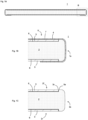
- a panel 1 according to one embodiment of the present invention has a base material 2, a surface material 3, and a skin material 4.
- the panel 1 has a substantially rectangular parallelepiped shape.
- the panel 1 can be used as a luggage board or the like installed in the luggage compartment of a vehicle.
- the base material 2 is a plate-shaped member.
- the base material 2 may be a foamed body or a non-foamed body.
- the base material 2 may also be a hollow body or a solid body.
- the base material 2 is formed by molding with a mold. In this case, since the base material 2 can be made into the desired shape before the panel 1 is manufactured, handleability is excellent. In addition, since the base material 2 can be made into the shape corresponding to the desired panel shape, a shape-optimized product can be obtained.
- Examples of the base material 2 include a bead foam molded body obtained by bead foam molding, a foamed or non-foamed sheet molded body obtained by imparting an uneven shape to one foamed or non-foamed resin sheet, and a foamed or non-foamed hollow molded body obtained by molding a tubular parison or two resin sheets which is foamed or non-foamed.
- the bead foam molded body can be configured of, for example, a foamed polystyrene, a foamed acrylonitrilestyrene, a foamed polypropylene, or the like.
- the foaming rate is, for example, 20 to 50 times, specifically for example, 20, 25, 30, 35, 40, 45, or 50 times, and may be in the range between the two values exemplified herein.
- the foamed parison or the foamed resin sheet can be configured of a polyolefin such as polyethylene and polypropylene.
- the foaming rate of the foamed body using this is, for example, 1.1 to 8 times, specifically for example, 1.1, 1.5, 2, 3, 4, 5, 6, 7, or 8 times, and may be in the range between the two values exemplified herein.
- the thickness of the base material 2 is, for example, 5 to 25 mm, and preferably 8 to 20 mm.
- the thickness is, specifically for example, 5, 6, 7, 8, 9, 10, 11, 12, 13, 14, 15, 20, or 25 mm, and may be in the range between the two values exemplified herein.
- the thickness of the base material 2 represents a distance at a part where the distance between the front surface 2f and the rear surface 2r of the base material 2 is the longest.
- the base material 2 is provided with a recessed part 5.
- Each of the front surface 2f and the rear surface 2r of the base material 2 is provided with one recessed part 5.
- the surface material 3 is fixed inside each of the recessed parts 5.
- the planar shape of the recessed part 5 (the shape when the base material 2 is viewed from the upper direction in Fig. 1A ) is a substantially rectangular shape.
- the surface material 3 is a plate-shaped member, and rigidity of the panel 1 can be increased by fixing the surface material 3 inside the recessed part 5. For this reason, the thickness of the base material 2 can be reduced, thereby enabling to reduce the weight of the panel 1.
- the surface material 3 can be configured of a material having higher rigidity per unit thickness than that of the base material 2.
- the surface material 3 can be configured of a metal such as aluminum and iron, a fiber reinforced resin, or the like.
- the thickness of the surface material 3 is, for example, 0.1 to 3 mm, and preferably 0.3 to 1.5 mm.
- the thickness is, specifically for example, 0.1, 0.2, 0.3, 0.4, 0.5, 0.6, 0.7, 0.8, 0.9, 1.0, 1.5, 2.0, 2.5, or 3.0 mm, and may be in the range between the two values exemplified herein. In the present specification, values such as thickness and depth represent average values, unless otherwise specified.
- the method of fixing the surface material 3 inside the recessed part 5 is not particularly limited.
- the surface material 3 may be welded to the base material 2, or adhered to the base material 2 via an adhesion layer 6.
- the adhesive constituting the adhesive layer 6 include urethane-based adhesives and olefin-based adhesives.
- the thickness of the adhesion layer 6 is, for example, 0.01 to 0.5 mm, specifically for example, 0.01, 0.05, 0.1, 0.2, 0.3, 0.4, or 0.5 mm, and may be in the range between the two values exemplified herein.
- S2/S1 is, for example, 0.8 to 1, and preferably 0.9 to 1. In this case, almost all of the recessed part 5 is covered by the surface material 3, increasing the rigidity of the panel 1.
- S2/S1 is, specifically for example, 0.80, 0.81, 0.82, 0.83, 0.84, 0.85, 0.86, 0.87, 0.88, 0.89, 0.90, 0.91, 0.92, 0.93, 0.94, 0.95, 0.96, 0.97, 0.98, 0.99, or 1.00, and may be in the range between the two values exemplified herein.
- the depth of the recessed part 5 is set such that the step difference between the edge 5a of the recessed part 5 and the edge 3c of the surface material 3 is small, and preferably it is set such that no step difference exists. If the step difference exists, the edge 5a may be higher, or the edge 3c may be higher. If the step difference is defined as S and the thickness of the surface material 3 is defined as T1, S/T1 is preferably 0.8 or less. In this case, the step difference is smaller than in the case that the surface material 3 is arranged on the base material 2 without providing the recessed part 5.
- the value is, for example, 0 to 0.8, specifically for example, 0, 0.1, 0.2, 0.3, 0.4, 0.5, 0.6, 0.7, or 0.8, and may be in the range between the two values exemplified herein.
- the depth of the recessed part 5 is made consistent with the total thickness of the surface material 3 and the adhesion layer 6. In this case, the step difference between the edge 5a of the recessed part 5 and the edge 3c of the surface material 3 can be eliminated.
- the depth of the recessed part 5 is, for example, 0.1 to 3 mm, and preferably 0.3 to 1.5 mm.
- the depth is, specifically for example, 0.1, 0.2, 0.3, 0.4, 0.5, 0.6, 0.7, 0.8, 0.9, 1.0, 1.5, 2.0, 2.5, or 3.0 mm, and may be in the range between the two values exemplified herein.
- D/T is, for example, 0.01 to 0.3, and preferably 0.02 to 0.2.
- the value is, specifically for example, 0.01, 0.02, 0.03, 0.04, 0.05, 0.06 ,0.07 0.08, 0.09, 0.1, 0.2, or 0.3, and may be in the range between the two values exemplified herein.
- the width W of a periphery 2b between the edge 5a of the recessed part 5 and a side end 2a of the base material 2 is 1 to 20 mm.
- the width W is, specifically for example, 1, 2, 3, 4, 5, 6, 7, 8, 9, 10, 11, 12, 13, 14, 15, 16, 17, 18, 19, or 20 mm, and may be in the range between the two values exemplified herein.
- the width W of the periphery 2b is constant over the entire circumference of the base material 2. If the width W is not constant over the entire circumference, preferably the average value thereof is within the range described above, and more preferably both of the minimum and maximum values thereof are within the range described above.
- the skin material 4 is arranged to cover the base material 2 and the surface material 3.
- the skin material 4 covers the surface material 3 arranged inside the recessed part 5 of the front surface 2f of the base material 2, the periphery 2b of the front surface 2f of the base material 2, and the side surface 2s of the base material 2. This improves the aesthetic appearance in applications where the front surface 1f and the side surface 1s of the panel 1 are easily viewed by the user (e.g., luggage board).
- the interface between the base material 2 and the surface material 3 is covered by the skin material 4, delamination of the surface material 3 from the base material 2 is suppressed.
- the skin material 4 covers a part or all of the surface material 3 arranged inside the recessed part 5 of the rear surface 2r of the base material 2 and the periphery 2b of the rear surface 2r of the base material 2. This suppresses delamination of the surface material 3 on the side of the rear surface 2r from the base material 2 because the interface between the base material 2 and the surface material 3 on the side of the rear surface 2r is covered by the skin material 4.
- the skin material 4 is, in one example, a nonwoven fabric, and can be adhered to the surface material 3 and the base material 2 via the adhesive layer 7.
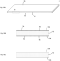
- the panel 1 can be manufactured by the following method.
- the base material preparation step the base material 2 having the recessed part 5 is prepared.
- the surface material 3 is fixed inside the recessed part 5 of the base material 2.
- the surface material 3 can be fixed by, for example, welding or adhesion.
- adhesion an adhesion layer is arranged between the base material 2 and the surface material 3, and thereafter the surface material 3 is pressed against the bottom surface 5c of the recessed part 5, thereby enabling to fix the surface material 3 to the bottom surface 5c of the recessed part 5.
- the adhesion layer can be arranged by applying an adhesive to the bottom surface 5c of the recessed part 5 or the surface material 3 (e.g., spray coating and bead coating).
- an adhesive is applied to the part to fix the skin material 4 (the surface material 3 and the base material 2), and then the skin material 4 is pressed against the part to which the adhesive is applied, thereby enabling to fixing the skin material 4 to the surface material 3 and the base material 2.
- the base material 2 having the recessed part 5 was prepared and then the surface material 3 was fixed inside the recessed part 5.
- the recessed part 5 may be formed on the base material 2 by preparing the base material 2 not having the recessed part 5 and by pressing the surface material 3 against the base material 2 with the surface material 3 placed on the base material 2 to sink the surface material 3 into the base material 2.
- the surface material 3 can also be fixed inside the recessed part 5 by such a method.
- the base material 2 is preferably configured of a material that is easily recessed by pressing (e.g., a foam, especially a bead foam molded body).
- the step of pressing the surface material 3 against the base material 2 may be performed with or without an adhesive layer arranged between the base material 2 and the surface material 3.
- the surface material 3 can be fixed to the base material 2 by pressing the surface material 3 against the base material 2 to form the recessed part 5, and then pressing the surface material 3 against the base material 2 with the adhesive layer arranged between the base material 2 and the surface material 3.
- the former is preferable because the number of steps is small.
- the pressing can be performed using, for example, a pressing roller, a pressing machine, or the like.
- the skin material fixing step can be performed similarly to "2. Method of Manufacturing Panel 1".
- a panel 1 according to one embodiment of the present invention has a base material 2, a surface material 3, and a skin material 4.
- the panel 1 has a substantially rectangular parallelepiped shape.
- the panel 1 can be used as a luggage board or the like installed in the luggage compartment of a vehicle.
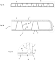
- the base material 2 comprises a front wall 21 and a rear wall 22, and comprises a rib 23 configured by recessing a part of the rear wall 22 toward the front wall 21 and welding the part of the rear wall 22 to an inner surface of the front wall 21.
- the front wall 21 and the rear wall 22 can be configured of a resin composition.
- the resin composition contains a resin and may contain an additive such as a filler.
- the resin include olefin resins such as polyethylene and polypropylene.
- the filler include fibrous fillers such as glass fibers and carbon fibers, and particle fillers such as talc and mica.
- the addition of the filler can increase the rigidity and decrease the linear expansion coefficient.
- the filler content is, for example, 20 to 50 mass%, and preferably 30 to 40 mass%. The content is, for example, 20, 25, 30, 35, 40, 45, or 50 mass%, and may be in the range between the two values exemplified herein.
- the filler content of the rear wall 22 is preferably lower than that of the front wall 21.
- the rigidity of the panel 1 on the side of the rear wall 22 is low, but it can be increased by providing the surface material 3.
- the panel 1 that is particularly lightweight and highly rigid can be obtained by making the filler content of the rear wall 22 lower than that of the front wall 21 and reinforcing the rear wall 22 with the surface material 3.
- Each of the wall thicknesses of the front wall 21 and the rear wall 22 at parts other than the rib 23 is, for example, 0.5 to 2.0 mm, and preferably 0.8 to 1.5 mm.
- the thicknesses are, for example, 0.5, 0.6, 0.7, 0.8, 0.9, 1.0, 1.1, 1.2, 1.3, 1.4, 1.5, 1.6, 1.7, 1.8, 1.9, or 2.0 mm, and may be in the range between the two values exemplified herein.
- values such as wall thickness, thickness, and depth represent average values, unless otherwise specified.
- the wall thickness of the rear wall 22 is preferably smaller than that of the front wall 21.
- the weight of the panel 1 can be reduced while increasing the rigidity of the panel 1 on the side of the front wall 21.
- the rigidity of the panel 1 on the side of the rear surface 22 can be increased by providing the surface material 3.
- the panel 1 that is particularly lightweight and highly rigid can be obtained by making the wall thickness of the rear wall 22 smaller than that of the front wall 21 and reinforcing the rear wall 22 with the surface material 3.
- Tr/Tf is, for example, 0.1 to 0.9, and preferably 0.3 to 0.7. Tr/Tf is, for example, 0.1, 0.2, 0.3, 0.4, 0.5, 0.6, 0.7, 0.8, or 0.9, and may be in the range between the two values exemplified herein.
- the front wall 21 and the rear wall 22 may be foamed or non-foamed.
- the foaming rate of the rear wall 22 is preferably higher than that of the front wall 21.
- the rigidity of the panel 1 on the side of the rear wall 22 is low, but it can be increased by providing the surface material 3.
- the panel 1 that is particularly lightweight and highly rigid can be obtained by making the foaming rate of the rear wall 22 higher than that of the front wall 21 and reinforcing the rear wall 22 with the surface material 3.
- the opening shape of the rib 23 is not particularly limited and may be a circular shape, an elliptic shape, a rectangular shape, a polygonal shape, or the like.
- the bottom part of the rib 23 is a welded part 8 at which the front wall 21 and the rear wall 22 are welded together. At the welded part 8, the front wall 21 and the rear wall 22 are preferably compressed, and the wall thickness of the welded part 8 is preferably smaller than the total of the wall thicknesses of the front wall 21 and the rear wall 22.
- Tw/ (Tf/Tr) is, for example, 0.5 to 0.95, for example, 0.50, 0.55, 0.60, 0.65, 0.70, 0.75, 0.80, 0.85, 0.90, or 0.95, and may be in the range between the two values exemplified herein.
- Tw/Tf is, for example, 0.8 to 1.2, for example, 0.80, 0.85, 0.90, 0.95, 1.00, 1.05, 1.10, 1.15, or 1.20, and may be in the range between the two values exemplified herein.
- the base material 2 is provided with a plurality of ribs 23.
- the plurality of ribs 23 are arranged regularly and dispersedly. In this case, the rigidity of the panel 1 is particularly high.
- the thickness T of the thickest part of the base material 2 is, for example, 5 to 25 mm, and preferably 8 to 20 mm.
- the thickness is, specifically for example, 5, 6, 7, 8, 9, 10, 11, 12, 13, 14, 15, 20, or 25 mm, and may be in the range between the two values exemplified herein.
- the base material 2 can be formed by molding a pair of resin sheets 31 and 32 using a pair of molds 41 and 42, as shown in Fig. 5 .
- a parting line PL is formed on the base material 2 at a position corresponding to the parting surface of the molds 41 and 42.
- the front wall 21 and the rear wall 22 are welded at the parting line PL.
- the parting line PL formed on the base material 2 is preferably provided at the position adjacent to the edge 2c on the side of the rear wall 22 in a thickness direction of the base material 2.
- the skin material 4 is integrally molded, although the skin material 4 arranged on the side of the front wall 21 is supposed to cover the region leading to the position of the parting line PL, almost the entire side surface 2s of the base material 2 is covered with the skin material 4 by providing the parting line PL at the position adjacent to the edge 2c, thereby leading to the advantage of excellent aesthetical appearance.
- edge 2c is preferably provided at the protruding part 2d that protrudes from the side surface 2s of the base material 2.
- the welded width of the front wall 21 and the rear wall 22 is increased by providing the protruding part 2d and the strength of the parting line PL is improved.
- the surface material 3 is a plate-shaped member, and is fixed on the rear wall 22 to cover the opening 23a of the rib 23. This can increase the rigidity of the panel 1. For this reason, it becomes unnecessary to provide the bar-shaped reinforcing material in the panel 1, thereby enabling to reduce the weight of the panel 1.
- designability of the rear surface 1r of the panel 1 can be enhanced by covering the opening 23a of the rib 23 by the surface material 3.
- the surface material 3 covers the opening 23a of at least one of the ribs 23 provided on the rear wall 22. It preferably covers the openings 23a of the plurality of the ribs 23, and more preferably covers the openings 23a of all the ribs 23. Descriptions of the material, thickness, and the like of the surface material 3 are the same as those in the first perspective.
- the method of fixing the surface material 3 to the rear wall 22 is the same as the method of fixing the surface material 3 inside the recessed part 5 in the first perspective.
- the recessed part 5 is provided on the rear wall 22 and the surface material 3 is provided inside the recessed part 5. Owing to this, the interface between the rear wall 22 and the surface material 3 is arranged inside the recessed part 5, and thus external force is not likely to be applied, thereby suppressing delamination of the rear wall 22 and the surface material 3.
- the recessed part 5 is preferably provided in the area including the plurality of ribs 23.
- the planar shape of the outer circumference of the recessed part 5 (the shape when the base material 2 is viewed from the lower direction in Fig. 4A ) is a substantially rectangular shape.
- S1 the area of the region encompassed by the outer circumference of the recessed part 5
- S2 the area of the surface of the surface material 3 opposing to the recessed part 5
- T thickness of the thickest part of the base material 2
- D depth of the recessed part 5
- the skin material 4 is arranged to cover the front surface 2f and the side surface 2s of the base material 2, thereby enabling to improve the designability of the front surface 2f and the side surface 2s.
- the skin material 4 may cover the base material 2 and the surface material 3 on the rear surface 2r of the base material 2.
- the skin material 4 is a nonwoven fabric. The skin material 4 can be omitted if unnecessary.
- the panel 1 can be manufactured by the following method.
- a pair of resin sheets 31 and 32 in a molten state can be molded using a pair of openable/closable molds 41 and 42, as shown in Fig. 5 .
- the resin sheets 31 and 32 become the front wall 21 and the rear wall 22, respectively.
- the skin material 4 can be welded to the front wall 21 (i.e., integrally molded) when manufacturing the base material 2.
- the resin sheets 31 and 32 can be formed by extruding the resin composition from a T-die.
- the base material 2 with the skin material 4 welded thereto can be obtained by vacuum-suctioning the resin sheets 31 and 32 with the molds 41 and 42, then forming the resin sheets 31 and 32 into the shapes of the molding surfaces 41a and 42a of the molds 41 and 42, respectively, and thereafter closing the molds 41 and 42.
- the skin material 4 may be welded or adhered to the base material after the base material 2 is manufactured, without arranging the skin material 4 between the mold 41 and the resin sheet 31.
- the surface material 3 is fixed to the rear wall 22.
- the surface material 3 can be fixed by welding or adhesion, for example.
- adhesion the surface 3 can be fixed to the rear wall 22 by applying an adhesive to the rear wall 22 (e.g., spray coating, bead coating) and then pressing the surface material 3 against the rear wall 22.
- the panel 1 has a core material 12 and a surface material 3.
- the panel 1 has a substantially rectangular parallelepiped shape.
- the panel 1 can be used as a luggage board or the like installed in the luggage compartment of a vehicle.
- the core material 12 is preferably a plate-shaped member.
- the thickness of the core material 12 is, for example, 5 to 25 mm, and preferably 8 to 20 mm.
- the thickness is, specifically for example, 5, 6, 7, 8, 9, 10, 11 ,12, 13, 14, 15, 20, or 25 mm, and may be in the range between the two values exemplified herein.
- the thickness of the core material 12 represents a distance at a part where the distance between a first major surface 12a and a second major surface 12b of the core material 12 opposing to each other is the longest.
- the core material 12 is preferably provided with a recessed part, and the surface material 3 is fixed inside the recessed part, which suppresses delamination of the surface material 3 from the core material 12.
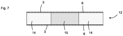
- the core material 12 has a base material 14 and a reinforcing material 15.
- the reinforcing material 15 is configured of a material having strength higher than that of the base material 14.
- the reinforcing material 15 include a metal, a wood, and a resin.
- the resin may be a foamed body or a non-foamed body.
- "strength” represents a Young's modulus at 25°C.
- the value of ⁇ strength of the reinforcing material 15/strength of the base material 14 ⁇ is, for example, 1.1 or greater, preferably 1.5 or greater, and preferably 2 or greater.
- the value is, for example, 1.1 to 1000, specifically for example, 1.1, 1.5, 2, 3, 4, 5, 6, 7, 8, 9, 10, 20, 50, 100, or 1000, and may be in the range between the two values exemplified herein.
- the base material 14 and the reinforcing material 15 are formed of a foamed body, and the foaming rate of the reinforcing material 15 is lower than that of the base material 14. Since strength of a foamed body is higher as the foaming rate is lower, the strength of the reinforcing material 15 can be made higher than that of the base material 14 by making the foaming rate of the reinforcing material 15 lower than that of the base material 14.
- the base material 14 and the reinforcing material 15 are configured of the same resin. In this case, since the base material 14 and the reinforcing material 15 are easily welded together, the base material 14 and the reinforcing material 15 are easily integrated by insert molding, for example.
- M1/M2 is, for example, 0.1 to 0.9, specifically for example, 0.1, 0.2, 0.3, 0.4, 0.5, 0.6, 0.7, 0.8, or 0.9, and may be in the range between the two values exemplified herein.
- the specific gravity of the reinforcing material 15 is normally greater than that of the base material 14.
- the value of ⁇ the specific gravity of the reinforcing material 15/the specific gravity of the base material 14 ⁇ is, for example, 1.1 or greater.
- the value is, for example, 1.1 to 1000, specifically for example, 1.1, 1.5, 2, 3, 4, 5, 6, 7, 8, 9, 10, 20, 50, 100, or 1000, and may be in the range between the two values exemplified herein.
- the reinforcing material 15 is preferably an elongated member. If the length in the longitudinal direction is defined as L and the diameter of the circumscribed circle at the part where the diameter of the circumscribed circle is the largest in the cross-section perpendicular to the longitudinal direction is defined as D, L/D is preferably 5 or greater, more preferably 10 or greater, and even more preferably 20 or greater. L/D is, for example, 5 to 1000, specifically for example, 5, 10, 15, 20, 50, 100, or 1000, and may be in the range between the two values exemplified herein. Preferably, the cross-sectional shape of the reinforcing material 15 is constant along the longitudinal direction.
- the reinforcing material 15 can be provided at an arbitrary position in the core material 12 and provided in an arbitrary size. However, since the specific gravity of the reinforcing material 15 is usually greater than that of the base material 14, the amount of the reinforcing material 15 used is preferably minimized to suppress the increase in weight.
- V2/V1 is preferably 0.5 or less, and more preferably 0.3 or less.
- V2/V1 is, for example, 0.001 to 0.5, specifically for example, 0.001, 0.01, 0.1, 0.2, 0.3, 0.4, or 0.5, and may be in the range between the two values exemplified herein.
- W2/W1 is preferably 0.8 or less, more preferably 0.5 or less, and even more preferably 0.3 or less.
- W2/W1 is, for example, 0.001 to 0.8, specifically for example, 0.001, 0.01, 0.1, 0.2, 0.3, 0.4, 0.5, 0.6, 0.7, or 0.8, and may be in the range between the two values exemplified herein.
- the reinforcing material 15 is arranged such that the longitudinal direction of the reinforcing material 15 is along the longitudinal or lateral direction of the core material 12.
- L/LC is preferably 0.5 or greater, and preferably 0.8 or greater.
- the strength of the panel 1 can be increased over a wide area of the panel 1.
- L/LC is, for example, 0.5 to 1.0, specifically for example, 0.5, 0.6, 0.7, 0.8, 0.9, or 1.0, and may be in the range between the two values exemplified herein.
- the ratio of the thickness of the reinforcing material 15 to the thickness of the core material 12 is, for example, 0.1 to 1.0, specifically for example, 0.1, 0.2, 0.3, 0.4, 0.5, 0.6, 0.7, 0.8, 0.9, or 1.0, and may be in the range between the two values exemplified herein.
- the length of the core material in the lateral direction is, for example, 10 to 100 mm, and preferably 20 to 40 mm.
- the length is, specifically for example, 10, 20, 30, 40, 50, 60, 70, 80, 90, or 100 mm, and may be in the range between the two values exemplified herein.
- the reinforcing material 15 is preferably arranged at the position where DILL becomes 0.20 to 0.45 such that the longitudinal direction of the reinforcing material 15 is along the lateral direction of the core material 12.
- a relatively large luggage 18 is placed near the center of the longitudinal direction of the panel 1 while both ends of the longitudinal direction of the panel 1 are supported by the support member 17, the panel 1 tends to buckle at the position where DILL becomes 0.20 to 0.45.
- D/LL is, specifically for example, 0.20, 0.25, 0.30, 0.35, 0.40, or 0.45, and may be in the range between the two values exemplified herein.
- the reinforcing material 15 may be provided throughout the entire thickness of the core material 12, or only in a part in the thickness direction. The reinforcing material 15 may be exposed on only one side of the core material 12 or on both sides of the core material 12.
- the base material 14 and the reinforcing material 15 is preferably flush with each other. This makes it easy to adhere the base material 14 and the reinforcing material 15 to the surface material 3.
- the surface material 3 is a plate-shaped member and is fixed to the core material 12 by being adhered to the base material 14 and the reinforcing material 15. By adhering the surface material 3 to the reinforcing material 15 as well as the base material 14, the surface material 3 and the reinforcing material 15 are integrated, by which the reinforcing effect due to providing the reinforcing material 15 becomes prominent and an abnormal noise generated by the reinforcing material 15 interfering with other members during vibration is suppressed.
- the surface material 3 can be configured of a material having the strength per unit thickness higher than that of the base material 14. Descriptions of the material, thickness, and the like of the surface material 3 are the same as those in the first perspective.
- the method of adhering the surface material 3 to the base material 14 and the reinforcing material 15 via the adhesive layer 6 is the same as the method of fixing the surface material 3 inside the recessed part 5 in the first perspective.
- the surface material 3 may be provided on only one of the first major surface 12a and the second major surface 12b of the core material 12, or on both the first major surface 12a and the second major surface 12b.
- the panel 1 can be manufactured by the following method.
- the core material 12 is prepared.
- the core material 12 can be formed by insert molding in which the reinforcing material 15 is inserted during molding of the base material 14, or by preparing the base material 14 and the reinforcing material 15 separately and then joining (fitting, gluing, welding, etc.) both.
- each of the base material 14 and the reinforcing material 15 is adhered to the surface material 3.
- This adhesion can be performed by applying an adhesive onto the base material 14 and the reinforcing material 15 (e.g., spray coating, bead coating) and then pressing the surface material 3 against the base material 14 and the reinforcing material 15.
- an adhesive onto the base material 14 and the reinforcing material 15 e.g., spray coating, bead coating
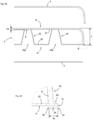
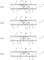
- the second embodiment of the present invention will be described with reference to Fig. 9A .
- the present embodiment is similar to the first embodiment, and the main difference is the configuration of the reinforcing material 15. Hereinafter, the difference will mainly be described.
- the reinforcing material 15 is H-shaped.
- the reinforcing material 15 has a column part 15a and flange parts 15b and 15c at both ends of the column part 15a, both the flange parts 15b and 15c adhered to the surface material 3.
- the H-shaped reinforcing material 15 has a high strength improving effect per volume, the strength of the panel 1 can be significantly increased by using the reinforcing material having such a shape.
- the strength improving effect is more prominent.
- the thicknesses of the flange parts 15b and 15c are, for example, 0.5 to 5 mm, and preferably 1 to 3 mm.
- the thicknesses are, specifically for example, 0.5, 1.0, 1.5, 2.0, 2.5, 3.0, 3.5, 4.0, 4.5, or 5.0 mm, and may be in the range between the two values exemplified herein.
- the third embodiment of the present invention will be described with reference to Fig. 9B .
- the present embodiment is similar to the second embodiment, and the main difference is a form in which the reinforcing material 15 is adhered to the surface material 3.
- the difference will mainly be described.
- the configuration of the reinforcing material 15 is the same as that in the second embodiment. However, only the flange part 15b is adhered to the surface material 3 and the flange part 15c is not adhered to the surface material 3. Effects of strength improvement and noise suppression are achieved even in such a form.
- the fourth embodiment of the present invention will be described with reference to Fig. 9C .
- the present embodiment is similar to the third embodiment, and the main difference is the configuration of the reinforcing material 15. Hereinafter, the difference will mainly be described.
- the reinforcing material 15 has the flange part 15b at one end of the column part 15a, and no flange part is provided at the other end of the column part 15a.
- the flange part 15b is adhered to the surface material 3.
- the other end of the column part 15a may or may not be adhered to the surface material. Effects of strength improvement and noise suppression are achieved even in such a form.
- the fifth embodiment of the present invention will be described with reference to Fig. 9D .
- the present embodiment is similar to the fourth embodiment, and the main difference is the configuration of the reinforcing material 15. Hereinafter, the difference will mainly be described.
- the reinforcing material 15 has the flange part 15b at one end of the column part 15a, and no flange is provided at the other end of the column part 15a.
- the flange part 15b is adhered to the surface material 3.
- the other end of the column part 15a does not reach the surface material 3, and extends to the middle part of the core material 12. Effects of strength improvement and noise suppression are achieved even in such a form.
- a skin material may be provided to cover the core material 12 and the surface material 3 if necessary. This enables to improve the aesthetic appearance and to suppress delamination of the surface material 3 from the core material 12.
- the skin material is a nonwoven fabric, and can be adhered to the surface material 3 and the core material 12 via an adhesive layer.
- the panel 1 has the core material 12, the first surface material 3a, and the second surface material 3b.
- the core material 12 is interposed between the surface materials 3a and 3b.
- the panel 1 has a substantially rectangular parallelepiped shape.
- the panel 1 can be used as a luggage board or the like installed in the luggage compartment of a vehicle.
- L1 is, for example, 600 to 1200 mm, specifically for example, 600, 700, 800, 900, 1000, 1100, or 1200 mm, and may be in the range between the two values exemplified herein.
- L2 is 300 to 1200 mm, specifically for example, 300, 400, 500, 600, 700, 800, 900, 1000, 1100, or 1200 mm, and may be in the range between the two values exemplified herein.
- the value of L2/L1 is, for example, 0.3 to 1, specifically for example, 0.3, 0.4, 0.5, 0.6, 0.7, 0.8, 0.9, or 1.0, and may be in the range between the two values exemplified herein.
- the areal density of the panel 1 is preferably 3000 g/m 2 or lower from the viewpoint of reducing the weight of the panel 1.
- the areal density is, for example, 1500 to 3000 g/m 2 , specifically for example, 1500, 1600, 1700, 1800, 1900, 2000, 2100, 2200, 2300, 2400, 2500, 2600, 2700, 2800, 2900, or 3000 g/m 2 , and may be in the range between the two values exemplified herein.
- the core material 12 is preferably a plate-shaped member.
- the thickness of the core material 12 is 15 to 25 mm, and preferably 18 to 22 mm. When the core material 12 is too thin, the overall deflection of the panel 1 is too large. On the other hand, when the core material 12 is too thick, the weight of the panel 1 is too large.
- the thickness is, specifically for example, 15, 16, 17, 18, 19, 20, 21, 22, 23, 24, or 25 mm, and may be in the range between the two values exemplified herein.
- the thickness of the core material 12 represents a distance at a part where the distance between the first major surface 12a and the second major surface 12b of the core material 12 opposing to each other is the greatest.
- the core material 12 is preferably provided with a recessed part, and the surface materials 3a and 3b are fixed inside the recessed part. This suppresses delamination of the surface materials 3a and 3b from the core material 12.
- the 10% compressive stress of the core material 12 is, for example, 0.1 to 1.0 MPa. When the value is too small, buckling deformation is likely to occur. When the value is too large, the weight of the panel 1 is likely to be excessive.
- the value is, specifically for example, 0.10, 0.15, 0.20, 0.25, 0.30, 0.35, 0.40, 0.45, 0.50, 0.55, 0.60, 0.65, 0.70, 0.75, 0.80, 0.85, 0.90, 0.95, or 1.00 MPa, and may be in the range between the two values exemplified herein.
- the 10% compressive stress of the core material 12 can be measured in accordance with JIS K 7220.
- the areal density of the core material 12 is, for example, 400 to 1000 g/m 2 , specifically for example, 400, 500, 600, 700, 800, 900, or 1000 g/m 2 , and may be in the range between the two values exemplified herein.
- the surface materials 3a and 3b are each a plate-shaped member and are adhered to the major surfaces 12a and 12b of the core material 12, respectively.
- the surface materials 3a and 3b can be configured of a material having rigidity per unit thickness higher than that of the core material 12.
- they can be configured of a metal such as aluminum and iron, a fiber reinforced resin, or the like.
- Each of the thicknesses of the surface materials 3a and 3b is, for example, 0.05 to 1 mm, and preferably 0.08 to 0.5 mm.
- the thicknesses are, for example, 0.05, 0.08, 0.10, 0.15, 0.20, 0.25, 0.30, 0.35, 0.40, 0.45, 0.50, 0.60, 0.70, 0.80, 0.90, or 1.00 mm, and may be in the range between the two values exemplified herein. In the present specification, values such as thickness and depth represent average values, unless otherwise specified.
- Each of the areal densities of the surface materials 3a and 3b is, for example, 400 to 1000 g/m 2 , specifically for example, 400, 500, 600, 700, 800, 900, or 1000 g/m 2 , and may be in the range between the two values exemplified herein.
- the surface materials 3a and 3b can be adhered to the core material 12 via the adhesive layers 6a and 6b, respectively.
- the adhesive constituting the adhesive layers 6a and 6b include urethane-based adhesives and olefin-based adhesives, and a one-pack type urethane-based adhesive is preferred.
- Each of the thicknesses of the adhesive layers 6a and 6b is, for example, 0.01 to 0.5 mm, specifically for example, 0.01, 0.05, 0.1, 0.2, 0.3, 0.4, or 0.5 mm, and may be in the range between the two values exemplified herein.
- Each of the areal densities of the adhesive layers 6a and 6b is, for example, 10 to 100 g/m 2 , specifically for example, 10, 20, 30, 40, 50, 60, 70, 80, 90, or 100 g/m 2 , and may be in the range between the two values exemplified herein.
- the first surface material strength index is defined by (the Young's modulus of the first surface material 3a [GPa]) x (the thickness of the first surface material 3a [mm]) 2
- the second surface material strength index is defined by (the Young's modulus of the second surface material 3b [GPa]) x (the thickness of the second surface material 3b [mm]) 2
- the average surface material strength index is defined as the average value of the first surface material strength index and the second surface material strength index
- the panel strength index defined by (the average surface material strength index) x (10% compressive stress of the core material [MPa]) is 0.7 or greater.
- the surface material strength index represents the strength of the surface material 3a or 3b.
- Each of the first surface material strength index, the second surface material strength index, and the average surface material strength index is preferably 1.5 or greater, and more preferably 10 or less.
- the value is, specifically for example, 1.5, 2.0, 2.5, 3.0, 3.5, 4.0, 4.5, 5.0, 5.5, 6.0, 6.5, 7.0, 7.5, 8.0, 8.5, 9.0, 9.5, or 10.0, and may be in the range between the two values exemplified herein.
- the panel strength index represents the strength correlated to the local strength in the panel 1.
- the panel strength index is 0.7 or greater, and preferably 5.0 or less. When the value is too small, buckling deformation is likely to occur. When the value is too large, the weight of the panel 1 is likely to be excessive.
- the value is, specifically for example, 0.7, 0.8, 0.9, 1.0, 1.1, 1.2, 1.3, 1.4, 1.5, 1.6, 1.7, 1.8, 1.9, 2.0, 2.1, 2.2, 2.3, 2.4, 2.5, 2.6, 2.7, 2.8, 2.9, 3.0, 3.1, 3.2, 3.3, 3.4, 3.5, 3.6, 3.7, 3.8, 3.9, 4.0, 4.1, 4.2, 4.3, 4.4, 4.5, 4.6, 4.7, 4.8, 4.9, or 5.0, and may be in the range between the two values exemplified herein.
- the buckling load (minimum value of load that causes buckling deformation) when the load is applied to the center of the panel 1 in the first direction by a pressing element whose contact surface is 50 mm in diameter in a state that two sides at both ends of the panel 1 in the first direction are supported is preferably 40 kg or more and 300 kg or less.
- the value is, specifically for example, 40, 50, 60, 70, 80, 90, 100, 150, 200, 250, or 300 kg, and may be in the range between the two values exemplified herein.
- the panel 1 can be manufactured by applying an adhesive onto the core material 12 (e.g., spray coating, bead coating) and then pressing the surface materials 3a and 3b against the core material 12.
- an adhesive e.g., spray coating, bead coating
- a skin material may be provided to cover the core material 12 and the surface materials 3a and 3b if necessary. This enables to obtain the improved aesthetic appearance and suppresses delamination of the surface materials 3a and 3b from the core material 12.
- the skin material is a nonwoven fabric, and can be adhered to the surface material 3a, the surface material 3b, and the core material 12 via an adhesive layer.
- the panel 1 with a flat shape of 1000 mm x 450 mm was manufactured using the core material 12, the surface material 3a, and the surface material 3b shown in Table 1.
- a one-pack type urethane-based adhesive was used as the adhesive to adhere the core material 12 to the surface materials 3a and 3b, and was applied such that the areal density is 60 g/m 2 .
- the materials and thicknesses of the surface materials 3a and 3b were identical.
- Al5052 was used as Al
- SUS304 was used as SUS.
- the core material 12 manufactured with heat pole GR (made by JSP Corporation) was used.
- a load was applied to the center of the panel 1 in the longitudinal direction by a pressing element whose contact surface is 50 mm in diameter in a state that two sides at both ends of the panel 1 in the longitudinal direction are supported.
- the load was increased by 10 kg and the buckling load was defined as the load when buckling deformation occurred.
- Table 1 The results are shown in Table 1.
Landscapes
- Engineering & Computer Science (AREA)
- Mechanical Engineering (AREA)
- Architecture (AREA)
- Civil Engineering (AREA)
- Structural Engineering (AREA)
- Life Sciences & Earth Sciences (AREA)
- Wood Science & Technology (AREA)
- Textile Engineering (AREA)
- Laminated Bodies (AREA)
Abstract


Description
- The present invention relates to a panel that can be used as a luggage board or the like installed in the luggage compartment of a vehicle.
- In
Patent Literature 1, disclosed is a panel material configured by attaching a thin plate-shaped steel plate to a hollow plate. - In
Patent Literature 2, disclosed is a panel having a plurality of ribs configured by recessing a part of the rear wall toward the front wall and welding the part of the rear wall to an inner surface of the front wall. - In
Patent Literature 1, disclosed is a panel configured by attaching a thin plate-shaped surface material to a core material. -
- [Patent Literature 1]
JP-A-2016-7900 - [Patent Literature 2]
WO2013/077198 - In the configuration of
Patent Literature 1, the interface between the steel plate and the hollow plate is arranged at a position where external force is easily applied, and delamination of the steel plate and the hollow plate may occur when external force is applied to the interface. - The present invention has been made in view of such a circumstance, and aims to provide a panel capable of suppressing delamination of a base material and a surface material.
- The panel of
Patent Literature 2 is provided with a bar-shaped reinforcing material inside thereof to increase rigidity. Since the bar-shaped reinforcing material is relatively heavy, the overall weight of the panel is increased by providing the reinforcing material. In addition, since the rib provided on the rear wall are exposed, the panel ofPatent Literature 2 does not have excellent designability of the rear surface. - The present invention has been made in view of such circumstances, and aims to provide a panel capable of reducing weight and excellent in designability of the rear surface.
- In
Patent Literature 1, strength is increased by attaching the steel plate to the hollow plate. However, in some cases, the strength may still be insufficient. To increase the strength, the thickness of the steel plate may be increased. In such a case, however, the weight of the panel is significantly increased. - The present invention has been made in view of such a circumstance, and aims to provide a panel capable of increasing the panel strength while suppressing the significant increase in the panel weight.
- Although such a panel as disclosed in
Patent Literature 1 has excellent strength, the inventors conducted a detailed study of the strength of the panel and found that buckling deformation that the panel is bended when a local load is applied to the surface material is likely to occur. - The present invention has been made in view of such a circumstance, and aims to provide a panel capable of suppressing occurrence of buckling deformation.
- According to the present invention, provided is a panel comprising a base material and a surface material, wherein the surface material is fixed inside a recessed part provided on a base material.
- In the panel of the present invention, the surface material is fixed inside the recessed part provided on the base material. For this reason, the interface between the base material and the surface material is arranged inside the recessed part, and external force is not applied easily to the interface, thereby suppressing delamination of the base material and the surface material.
- Hereinafter, various embodiments of the present invention are exemplified. The embodiments shown below can be combined with each other.
- Preferably, the panel described above, wherein the base material and the surface material are covered with a skin material.
- Preferably, the panel described above, wherein a width of a periphery between an edge of the recessed part and a side end of the base material is 1 to 20 mm.
- Preferably, the panel described above, wherein S/T1 is 0.8 or less, where S represents a step difference between the edge of the recessed part and an edge of the surface material, and T1 represents a thickness of the surface material.
- According to the present invention, provided is a panel comprising a base material and a surface material, wherein the base material comprises a front wall and a rear wall, and comprises a rib configured by recessing a part of the rear wall toward the front wall and welding the part of the rear wall to an inner surface of the front wall, and the surface material is fixed to the rear wall to cover an opening of the rib.
- Since the surface material is fixed to the rear wall, the panel of the present invention has high rigidity. In addition, since there is no need to provide a reinforcing material inside the panel, it is possible to reduce the weight. Besides, since the surface material covers the opening of the rib on the rear surface of the panel, the rib is not exposed and designability of the rear surface of the panel is excellent.
- Hereinafter, various embodiments of the present invention are exemplified. The embodiments shown below can be combined with each other.
- Preferably, the panel described above, wherein a recessed part is provided on the rear wall, and the surface material is provided inside the recessed part.
- Preferably, the panel described above, wherein a parting line formed on the base material is provided at a position adjacent to an edge on a side of the rear wall of the base material.
- According to the present invention, provided is a panel comprising a core material and a surface material, wherein the core material comprises a base material and a reinforcing material, the reinforcing material is configured of a material having strength higher than that of the base material, and each of the base material and the reinforcing material is adhered to the surface material.
- In the panel of the present invention, the core material is configured of the base material and the reinforcing material, and the reinforcing material is adhered to the surface material. In such a form, since strength can be increased by arranging the reinforcing material only where strength is needed, the amount of the reinforcing material used can be minimized. For this reason, it is possible to increase the panel strength while suppressing the significant increase in the panel weight.
- Hereinafter, various embodiments of the present invention are exemplified. The embodiments shown below can be combined with each other.
- Preferably, the panel described above, wherein the base material and the reinforcing material are configured of a foamed body, and a foaming rate of the foamed body configuring the reinforcing material is lower than that of the foamed body configuring the base material.
- Preferably, the panel described above, wherein the reinforcing material comprises a column part and a flange part, the flange part is provided at one end or both ends of the column part, and the flange part is adhered to the surface material.
- According to the present invention, provided is a panel comprising a core material, a first surface material, and a second surface material, wherein the core material is interposed between the first surface material and the second surface material, a thickness of the core material is 15 to 25 mm, the first surface material and the second surface material are adhered to the core material, a first surface material strength index is defined by (a Young's modulus of the first surface material [GPa]) x (a thickness of the first surface material [mm])2, a second surface material strength index is defined by (a Young's modulus of the second surface material [GPa]) x (a thickness of the second surface material [mm])2, an average surface material strength index is defined as an average value of the first surface material strength index and the second surface material strength index, and a panel strength index defined by (the average surface strength index) x (10% compressive stress of the core material [MPa]) is 0.7 or greater.
- The inventors conducted an intensive study and found that buckling deformation occurs by local deformation of the panel when a local load is applied to the panel. Based on this finding, the inventors found that occurrence of buckling deformation can be effectively suppressed by setting the panel strength index, which correlates to the local strength of the panel, to 0.7 or greater, thereby leading to completion of the invention.
- Hereinafter, various embodiments of the present invention are exemplified. The embodiments shown below can be combined with each other.
- Preferably, the panel described above, wherein the panel strength index is 5.0 or less.
- Preferably, the panel described above, wherein an areal density of the panel is 3000 g/m2 or lower.
-
-
Fig. 1A is a cross-sectional view of apanel 1 of one embodiment of the present invention. -
Fig. 1B is an enlarged view of a region B inFig. 1A . -
Fig. 1C is a figure showingFig. 1B without askin material 4 and anadhesive layer 7. -
Fig. 2 is an exploded view ofFig. 1B (adhesive layers -
-
Fig. 3A is a cross-sectional view of apanel 1 of one embodiment of the present invention. -
Fig. 3B is an enlarged view of a region B inFig. 3A . -
Fig. 3C is an enlarged view of a region C inFig. 3B . -
Fig. 4A is an exploded view ofFig. 3B . -
Fig. 4B is an enlarged view of a region B inFig. 4A . -
Fig. 5 is a cross-sectional view to explain a step of manufacturing abase material 2 with askin material 4 welded thereto. -
-
Fig. 6A is a perspective view of apanel 1 of one embodiment of the present invention. -
Fig. 6B is a perspective view of acore material 12. -
Fig. 7 is an enlarged view of an end surface in a region A inFig. 6A . -
Fig. 8 is a perspective view showing a state in which both ends of apanel 1 in a longitudinal direction are supported bysupport members 17. -
Figs. 9A to 9D are figures corresponding toFig. 7 , showing the second to fifth embodiments, respectively. -
-
Fig. 10A is a perspective view of apanel 1 of one embodiment of the present invention. -
Fig. 10B is an enlarged view of an end surface at a region B inFig. 10A . -
Fig. 10C is a figure showing only acore material 12 extracted fromFig. 10B . - Hereinafter, embodiments of the present invention will be described. Various distinctive features shown in the following embodiments can be combined with each other. In addition, the invention can be established independently for each of the distinctive features. The features described in embodiments of the first to fourth perspectives can be combined with each other.
- As shown in
Figs. 1A to 2 , apanel 1 according to one embodiment of the present invention has abase material 2, asurface material 3, and askin material 4. Preferably, thepanel 1 has a substantially rectangular parallelepiped shape. Thepanel 1 can be used as a luggage board or the like installed in the luggage compartment of a vehicle. - Preferably, the
base material 2 is a plate-shaped member. Thebase material 2 may be a foamed body or a non-foamed body. Thebase material 2 may also be a hollow body or a solid body. Preferably, thebase material 2 is formed by molding with a mold. In this case, since thebase material 2 can be made into the desired shape before thepanel 1 is manufactured, handleability is excellent. In addition, since thebase material 2 can be made into the shape corresponding to the desired panel shape, a shape-optimized product can be obtained. - Examples of the
base material 2 include a bead foam molded body obtained by bead foam molding, a foamed or non-foamed sheet molded body obtained by imparting an uneven shape to one foamed or non-foamed resin sheet, and a foamed or non-foamed hollow molded body obtained by molding a tubular parison or two resin sheets which is foamed or non-foamed. - The bead foam molded body can be configured of, for example, a foamed polystyrene, a foamed acrylonitrilestyrene, a foamed polypropylene, or the like. The foaming rate is, for example, 20 to 50 times, specifically for example, 20, 25, 30, 35, 40, 45, or 50 times, and may be in the range between the two values exemplified herein.
- The foamed parison or the foamed resin sheet can be configured of a polyolefin such as polyethylene and polypropylene. The foaming rate of the foamed body using this is, for example, 1.1 to 8 times, specifically for example, 1.1, 1.5, 2, 3, 4, 5, 6, 7, or 8 times, and may be in the range between the two values exemplified herein.
- The thickness of the
base material 2 is, for example, 5 to 25 mm, and preferably 8 to 20 mm. The thickness is, specifically for example, 5, 6, 7, 8, 9, 10, 11, 12, 13, 14, 15, 20, or 25 mm, and may be in the range between the two values exemplified herein. The thickness of thebase material 2 represents a distance at a part where the distance between thefront surface 2f and therear surface 2r of thebase material 2 is the longest. - The
base material 2 is provided with a recessedpart 5. Each of thefront surface 2f and therear surface 2r of thebase material 2 is provided with one recessedpart 5. Thesurface material 3 is fixed inside each of the recessedparts 5. Preferably, the planar shape of the recessed part 5 (the shape when thebase material 2 is viewed from the upper direction inFig. 1A ) is a substantially rectangular shape. - The
surface material 3 is a plate-shaped member, and rigidity of thepanel 1 can be increased by fixing thesurface material 3 inside the recessedpart 5. For this reason, the thickness of thebase material 2 can be reduced, thereby enabling to reduce the weight of thepanel 1. Thesurface material 3 can be configured of a material having higher rigidity per unit thickness than that of thebase material 2. For example, thesurface material 3 can be configured of a metal such as aluminum and iron, a fiber reinforced resin, or the like. The thickness of thesurface material 3 is, for example, 0.1 to 3 mm, and preferably 0.3 to 1.5 mm. The thickness is, specifically for example, 0.1, 0.2, 0.3, 0.4, 0.5, 0.6, 0.7, 0.8, 0.9, 1.0, 1.5, 2.0, 2.5, or 3.0 mm, and may be in the range between the two values exemplified herein. In the present specification, values such as thickness and depth represent average values, unless otherwise specified. - The method of fixing the
surface material 3 inside the recessedpart 5 is not particularly limited. Thesurface material 3 may be welded to thebase material 2, or adhered to thebase material 2 via anadhesion layer 6. Examples of the adhesive constituting theadhesive layer 6 include urethane-based adhesives and olefin-based adhesives. The thickness of theadhesion layer 6 is, for example, 0.01 to 0.5 mm, specifically for example, 0.01, 0.05, 0.1, 0.2, 0.3, 0.4, or 0.5 mm, and may be in the range between the two values exemplified herein. - If an area of a
bottom surface 5c of the recessedpart 5 is defined as S1 and an area of a surface of thesurface material 3 opposing to thebottom surface 5c of the recessedpart 5 is defined as S2, S2/S1 is, for example, 0.8 to 1, and preferably 0.9 to 1. In this case, almost all of the recessedpart 5 is covered by thesurface material 3, increasing the rigidity of thepanel 1. S2/S1 is, specifically for example, 0.80, 0.81, 0.82, 0.83, 0.84, 0.85, 0.86, 0.87, 0.88, 0.89, 0.90, 0.91, 0.92, 0.93, 0.94, 0.95, 0.96, 0.97, 0.98, 0.99, or 1.00, and may be in the range between the two values exemplified herein. - Preferably, the depth of the recessed
part 5 is set such that the step difference between theedge 5a of the recessedpart 5 and theedge 3c of thesurface material 3 is small, and preferably it is set such that no step difference exists. If the step difference exists, theedge 5a may be higher, or theedge 3c may be higher. If the step difference is defined as S and the thickness of thesurface material 3 is defined as T1, S/T1 is preferably 0.8 or less. In this case, the step difference is smaller than in the case that thesurface material 3 is arranged on thebase material 2 without providing the recessedpart 5. The value is, for example, 0 to 0.8, specifically for example, 0, 0.1, 0.2, 0.3, 0.4, 0.5, 0.6, 0.7, or 0.8, and may be in the range between the two values exemplified herein. Preferably, the depth of the recessedpart 5 is made consistent with the total thickness of thesurface material 3 and theadhesion layer 6. In this case, the step difference between theedge 5a of the recessedpart 5 and theedge 3c of thesurface material 3 can be eliminated. - The depth of the recessed
part 5 is, for example, 0.1 to 3 mm, and preferably 0.3 to 1.5 mm. The depth is, specifically for example, 0.1, 0.2, 0.3, 0.4, 0.5, 0.6, 0.7, 0.8, 0.9, 1.0, 1.5, 2.0, 2.5, or 3.0 mm, and may be in the range between the two values exemplified herein. - If the thickness of the
base material 2 is defined as T and the depth of the recessedpart 5 is defined as D, D/T is, for example, 0.01 to 0.3, and preferably 0.02 to 0.2. The value is, specifically for example, 0.01, 0.02, 0.03, 0.04, 0.05, 0.06 ,0.07 0.08, 0.09, 0.1, 0.2, or 0.3, and may be in the range between the two values exemplified herein. - Preferably, the width W of a
periphery 2b between theedge 5a of the recessedpart 5 and aside end 2a of thebase material 2 is 1 to 20 mm. When the width W is too small, the strength of theperiphery 2b may be too low and theperiphery 2b may be destroyed by external force. When the width W is too large, the region where thesurface material 3 does not exist may be too large, resulting in insufficient rigidity of thepanel 1. The width W is, specifically for example, 1, 2, 3, 4, 5, 6, 7, 8, 9, 10, 11, 12, 13, 14, 15, 16, 17, 18, 19, or 20 mm, and may be in the range between the two values exemplified herein. Preferably, the width W of theperiphery 2b is constant over the entire circumference of thebase material 2. If the width W is not constant over the entire circumference, preferably the average value thereof is within the range described above, and more preferably both of the minimum and maximum values thereof are within the range described above. - The
skin material 4 is arranged to cover thebase material 2 and thesurface material 3. Preferably, theskin material 4 covers thesurface material 3 arranged inside the recessedpart 5 of thefront surface 2f of thebase material 2, theperiphery 2b of thefront surface 2f of thebase material 2, and theside surface 2s of thebase material 2. This improves the aesthetic appearance in applications where thefront surface 1f and theside surface 1s of thepanel 1 are easily viewed by the user (e.g., luggage board). In addition, since the interface between thebase material 2 and thesurface material 3 is covered by theskin material 4, delamination of thesurface material 3 from thebase material 2 is suppressed. Preferably, theskin material 4 covers a part or all of thesurface material 3 arranged inside the recessedpart 5 of therear surface 2r of thebase material 2 and theperiphery 2b of therear surface 2r of thebase material 2. This suppresses delamination of thesurface material 3 on the side of therear surface 2r from thebase material 2 because the interface between thebase material 2 and thesurface material 3 on the side of therear surface 2r is covered by theskin material 4. - The
skin material 4 is, in one example, a nonwoven fabric, and can be adhered to thesurface material 3 and thebase material 2 via theadhesive layer 7. - The
panel 1 can be manufactured by the following method. - In the base material preparation step, the
base material 2 having the recessedpart 5 is prepared. - In the surface material fixing step, the
surface material 3 is fixed inside the recessedpart 5 of thebase material 2. Thesurface material 3 can be fixed by, for example, welding or adhesion. In the case of adhesion, an adhesion layer is arranged between thebase material 2 and thesurface material 3, and thereafter thesurface material 3 is pressed against thebottom surface 5c of the recessedpart 5, thereby enabling to fix thesurface material 3 to thebottom surface 5c of the recessedpart 5. The adhesion layer can be arranged by applying an adhesive to thebottom surface 5c of the recessedpart 5 or the surface material 3 (e.g., spray coating and bead coating). - In the skin material fixing step, an adhesive is applied to the part to fix the skin material 4 (the
surface material 3 and the base material 2), and then theskin material 4 is pressed against the part to which the adhesive is applied, thereby enabling to fixing theskin material 4 to thesurface material 3 and thebase material 2. - In "2. Method For
Manufacturing Panel 1," thebase material 2 having the recessedpart 5 was prepared and then thesurface material 3 was fixed inside the recessedpart 5. The recessedpart 5 may be formed on thebase material 2 by preparing thebase material 2 not having the recessedpart 5 and by pressing thesurface material 3 against thebase material 2 with thesurface material 3 placed on thebase material 2 to sink thesurface material 3 into thebase material 2. Thesurface material 3 can also be fixed inside the recessedpart 5 by such a method. In this case, thebase material 2 is preferably configured of a material that is easily recessed by pressing (e.g., a foam, especially a bead foam molded body). - The step of pressing the
surface material 3 against thebase material 2 may be performed with or without an adhesive layer arranged between thebase material 2 and thesurface material 3. In the latter case, thesurface material 3 can be fixed to thebase material 2 by pressing thesurface material 3 against thebase material 2 to form the recessedpart 5, and then pressing thesurface material 3 against thebase material 2 with the adhesive layer arranged between thebase material 2 and thesurface material 3. The former is preferable because the number of steps is small. The pressing can be performed using, for example, a pressing roller, a pressing machine, or the like. - In this manufacturing method, the skin material fixing step can be performed similarly to "2. Method of
Manufacturing Panel 1". -
- The
skin material 4 can be omitted if unnecessary. - The recessed
part 5 may be provided only on one of thefront surface 2f and therear surface 2r of thebase material 2. In this case, thesurface material 3 is arranged only on the surface where the recessedpart 5 exists. - As shown in
Figs. 3A and4B , apanel 1 according to one embodiment of the present invention has abase material 2, asurface material 3, and askin material 4. Preferably, thepanel 1 has a substantially rectangular parallelepiped shape. Thepanel 1 can be used as a luggage board or the like installed in the luggage compartment of a vehicle. - The
base material 2 comprises afront wall 21 and arear wall 22, and comprises arib 23 configured by recessing a part of therear wall 22 toward thefront wall 21 and welding the part of therear wall 22 to an inner surface of thefront wall 21. - The
front wall 21 and therear wall 22 can be configured of a resin composition. The resin composition contains a resin and may contain an additive such as a filler. Examples of the resin include olefin resins such as polyethylene and polypropylene. Examples of the filler include fibrous fillers such as glass fibers and carbon fibers, and particle fillers such as talc and mica. The addition of the filler can increase the rigidity and decrease the linear expansion coefficient. When the total of the resin and the filler is 100 mass%, the filler content is, for example, 20 to 50 mass%, and preferably 30 to 40 mass%. The content is, for example, 20, 25, 30, 35, 40, 45, or 50 mass%, and may be in the range between the two values exemplified herein. - The filler content of the
rear wall 22 is preferably lower than that of thefront wall 21. In this case, the rigidity of thepanel 1 on the side of therear wall 22 is low, but it can be increased by providing thesurface material 3. For this reason, thepanel 1 that is particularly lightweight and highly rigid can be obtained by making the filler content of therear wall 22 lower than that of thefront wall 21 and reinforcing therear wall 22 with thesurface material 3. - Each of the wall thicknesses of the
front wall 21 and therear wall 22 at parts other than therib 23 is, for example, 0.5 to 2.0 mm, and preferably 0.8 to 1.5 mm. The thicknesses are, for example, 0.5, 0.6, 0.7, 0.8, 0.9, 1.0, 1.1, 1.2, 1.3, 1.4, 1.5, 1.6, 1.7, 1.8, 1.9, or 2.0 mm, and may be in the range between the two values exemplified herein. In the present specification, values such as wall thickness, thickness, and depth represent average values, unless otherwise specified. - The wall thickness of the
rear wall 22 is preferably smaller than that of thefront wall 21. In this case, the weight of thepanel 1 can be reduced while increasing the rigidity of thepanel 1 on the side of thefront wall 21. In addition, the rigidity of thepanel 1 on the side of therear surface 22 can be increased by providing thesurface material 3. For this reason, thepanel 1 that is particularly lightweight and highly rigid can be obtained by making the wall thickness of therear wall 22 smaller than that of thefront wall 21 and reinforcing therear wall 22 with thesurface material 3. If the wall thickness of therear wall 22 is defined as Tr and the wall thickness of thefront wall 21 is defined as Tf, Tr/Tf is, for example, 0.1 to 0.9, and preferably 0.3 to 0.7. Tr/Tf is, for example, 0.1, 0.2, 0.3, 0.4, 0.5, 0.6, 0.7, 0.8, or 0.9, and may be in the range between the two values exemplified herein. - The
front wall 21 and therear wall 22 may be foamed or non-foamed. The foaming rate of therear wall 22 is preferably higher than that of thefront wall 21. In this case, the rigidity of thepanel 1 on the side of therear wall 22 is low, but it can be increased by providing thesurface material 3. For this reason, thepanel 1 that is particularly lightweight and highly rigid can be obtained by making the foaming rate of therear wall 22 higher than that of thefront wall 21 and reinforcing therear wall 22 with thesurface material 3. - The opening shape of the
rib 23 is not particularly limited and may be a circular shape, an elliptic shape, a rectangular shape, a polygonal shape, or the like. The bottom part of therib 23 is a weldedpart 8 at which thefront wall 21 and therear wall 22 are welded together. At the weldedpart 8, thefront wall 21 and therear wall 22 are preferably compressed, and the wall thickness of the weldedpart 8 is preferably smaller than the total of the wall thicknesses of thefront wall 21 and therear wall 22. If the wall thickness of the weldedpart 8 is defined as Tw, Tw/ (Tf/Tr) is, for example, 0.5 to 0.95, for example, 0.50, 0.55, 0.60, 0.65, 0.70, 0.75, 0.80, 0.85, 0.90, or 0.95, and may be in the range between the two values exemplified herein. In addition, Tw/Tf is, for example, 0.8 to 1.2, for example, 0.80, 0.85, 0.90, 0.95, 1.00, 1.05, 1.10, 1.15, or 1.20, and may be in the range between the two values exemplified herein. - Preferably, the
base material 2 is provided with a plurality ofribs 23. Preferably, the plurality ofribs 23 are arranged regularly and dispersedly. In this case, the rigidity of thepanel 1 is particularly high. - The thickness T of the thickest part of the
base material 2 is, for example, 5 to 25 mm, and preferably 8 to 20 mm. The thickness is, specifically for example, 5, 6, 7, 8, 9, 10, 11, 12, 13, 14, 15, 20, or 25 mm, and may be in the range between the two values exemplified herein. - In one example, the
base material 2 can be formed by molding a pair ofresin sheets molds Fig. 5 . A parting line PL is formed on thebase material 2 at a position corresponding to the parting surface of themolds front wall 21 and therear wall 22 are welded at the parting line PL. The parting line PL formed on thebase material 2 is preferably provided at the position adjacent to theedge 2c on the side of therear wall 22 in a thickness direction of thebase material 2. The advantages of providing the parting line PL at this position are that the parting line PL is inconspicuous and excellent in aesthetic appearance, and that the user is restrained from touching the parting line PL and feeling a sense of harm. In addition, in the case that theskin material 4 is integrally molded, although theskin material 4 arranged on the side of thefront wall 21 is supposed to cover the region leading to the position of the parting line PL, almost theentire side surface 2s of thebase material 2 is covered with theskin material 4 by providing the parting line PL at the position adjacent to theedge 2c, thereby leading to the advantage of excellent aesthetical appearance. - In addition, the
edge 2c is preferably provided at theprotruding part 2d that protrudes from theside surface 2s of thebase material 2. The welded width of thefront wall 21 and therear wall 22 is increased by providing theprotruding part 2d and the strength of the parting line PL is improved. - The
surface material 3 is a plate-shaped member, and is fixed on therear wall 22 to cover theopening 23a of therib 23. This can increase the rigidity of thepanel 1. For this reason, it becomes unnecessary to provide the bar-shaped reinforcing material in thepanel 1, thereby enabling to reduce the weight of thepanel 1. In addition, designability of therear surface 1r of thepanel 1 can be enhanced by covering theopening 23a of therib 23 by thesurface material 3. Thesurface material 3 covers theopening 23a of at least one of theribs 23 provided on therear wall 22. It preferably covers theopenings 23a of the plurality of theribs 23, and more preferably covers theopenings 23a of all theribs 23. Descriptions of the material, thickness, and the like of thesurface material 3 are the same as those in the first perspective. - The method of fixing the
surface material 3 to therear wall 22 is the same as the method of fixing thesurface material 3 inside the recessedpart 5 in the first perspective. - Preferably, the recessed
part 5 is provided on therear wall 22 and thesurface material 3 is provided inside the recessedpart 5. Owing to this, the interface between therear wall 22 and thesurface material 3 is arranged inside the recessedpart 5, and thus external force is not likely to be applied, thereby suppressing delamination of therear wall 22 and thesurface material 3. The recessedpart 5 is preferably provided in the area including the plurality ofribs 23. Preferably, the planar shape of the outer circumference of the recessed part 5 (the shape when thebase material 2 is viewed from the lower direction inFig. 4A ) is a substantially rectangular shape. - If the area of the region encompassed by the outer circumference of the recessed
part 5 is defined as S1 and the area of the surface of thesurface material 3 opposing to the recessedpart 5 is defined as S2, descriptions of S2/S1 are the same as those of S2/S1 in the first perspective. - Descriptions of the depth of the recessed
part 5 are the same as those of the recessedpart 5 in the first perspective. - If the thickness of the thickest part of the
base material 2 is defined as T and the depth of the recessedpart 5 is defined as D, descriptions of D/T are the same as those in the first perspective. - Descriptions of the width W of the
periphery 2b between theedge 5a of the recessedpart 5 and theedge 2c on the side ofrear wall 22 of thebase material 2 are the same as those in the first perspective. - Preferably, the
skin material 4 is arranged to cover thefront surface 2f and theside surface 2s of thebase material 2, thereby enabling to improve the designability of thefront surface 2f and theside surface 2s. Theskin material 4 may cover thebase material 2 and thesurface material 3 on therear surface 2r of thebase material 2. In one example, theskin material 4 is a nonwoven fabric. Theskin material 4 can be omitted if unnecessary. - The
panel 1 can be manufactured by the following method. - In one example, in the base material preparation step, a pair of
resin sheets closable molds Fig. 5 . Theresin sheets front wall 21 and therear wall 22, respectively. By arranging theskin material 4 between themold 41 and theresin sheet 31, theskin material 4 can be welded to the front wall 21 (i.e., integrally molded) when manufacturing thebase material 2. Theresin sheets - In one example, the
base material 2 with theskin material 4 welded thereto can be obtained by vacuum-suctioning theresin sheets molds resin sheets molds molds - The
skin material 4 may be welded or adhered to the base material after thebase material 2 is manufactured, without arranging theskin material 4 between themold 41 and theresin sheet 31. - In the surface material fixing step, the
surface material 3 is fixed to therear wall 22. Thesurface material 3 can be fixed by welding or adhesion, for example. In the case of adhesion, thesurface 3 can be fixed to therear wall 22 by applying an adhesive to the rear wall 22 (e.g., spray coating, bead coating) and then pressing thesurface material 3 against therear wall 22. - As shown in
Figs. 6A to 7 , thepanel 1 according to one embodiment of the present invention has acore material 12 and asurface material 3. Preferably, thepanel 1 has a substantially rectangular parallelepiped shape. Thepanel 1 can be used as a luggage board or the like installed in the luggage compartment of a vehicle. - The
core material 12 is preferably a plate-shaped member. The thickness of thecore material 12 is, for example, 5 to 25 mm, and preferably 8 to 20 mm. The thickness is, specifically for example, 5, 6, 7, 8, 9, 10, 11 ,12, 13, 14, 15, 20, or 25 mm, and may be in the range between the two values exemplified herein. The thickness of thecore material 12 represents a distance at a part where the distance between a firstmajor surface 12a and a secondmajor surface 12b of thecore material 12 opposing to each other is the longest. Thecore material 12 is preferably provided with a recessed part, and thesurface material 3 is fixed inside the recessed part, which suppresses delamination of thesurface material 3 from thecore material 12. Thecore material 12 has abase material 14 and a reinforcingmaterial 15. - Descriptions of the
base material 14 are the same as those of thebase material 2 in the first perspective. - The reinforcing
material 15 is configured of a material having strength higher than that of thebase material 14. Examples of the reinforcingmaterial 15 include a metal, a wood, and a resin. The resin may be a foamed body or a non-foamed body. In the present specification, "strength" represents a Young's modulus at 25°C. The value of {strength of the reinforcingmaterial 15/strength of the base material 14} is, for example, 1.1 or greater, preferably 1.5 or greater, and preferably 2 or greater. The value is, for example, 1.1 to 1000, specifically for example, 1.1, 1.5, 2, 3, 4, 5, 6, 7, 8, 9, 10, 20, 50, 100, or 1000, and may be in the range between the two values exemplified herein. - In the present embodiment, the
base material 14 and the reinforcingmaterial 15 are formed of a foamed body, and the foaming rate of the reinforcingmaterial 15 is lower than that of thebase material 14. Since strength of a foamed body is higher as the foaming rate is lower, the strength of the reinforcingmaterial 15 can be made higher than that of thebase material 14 by making the foaming rate of the reinforcingmaterial 15 lower than that of thebase material 14. Preferably, thebase material 14 and the reinforcingmaterial 15 are configured of the same resin. In this case, since thebase material 14 and the reinforcingmaterial 15 are easily welded together, thebase material 14 and the reinforcingmaterial 15 are easily integrated by insert molding, for example. If the foaming rate of the reinforcingmaterial 15 is defined as M1 and the foaming rate of thebase material 14 is defined as M2, M1/M2 is, for example, 0.1 to 0.9, specifically for example, 0.1, 0.2, 0.3, 0.4, 0.5, 0.6, 0.7, 0.8, or 0.9, and may be in the range between the two values exemplified herein. - The specific gravity of the reinforcing
material 15 is normally greater than that of thebase material 14. The value of {the specific gravity of the reinforcingmaterial 15/the specific gravity of the base material 14} is, for example, 1.1 or greater. The value is, for example, 1.1 to 1000, specifically for example, 1.1, 1.5, 2, 3, 4, 5, 6, 7, 8, 9, 10, 20, 50, 100, or 1000, and may be in the range between the two values exemplified herein. - The reinforcing
material 15 is preferably an elongated member. If the length in the longitudinal direction is defined as L and the diameter of the circumscribed circle at the part where the diameter of the circumscribed circle is the largest in the cross-section perpendicular to the longitudinal direction is defined as D, L/D is preferably 5 or greater, more preferably 10 or greater, and even more preferably 20 or greater. L/D is, for example, 5 to 1000, specifically for example, 5, 10, 15, 20, 50, 100, or 1000, and may be in the range between the two values exemplified herein. Preferably, the cross-sectional shape of the reinforcingmaterial 15 is constant along the longitudinal direction. - The reinforcing
material 15 can be provided at an arbitrary position in thecore material 12 and provided in an arbitrary size. However, since the specific gravity of the reinforcingmaterial 15 is usually greater than that of thebase material 14, the amount of the reinforcingmaterial 15 used is preferably minimized to suppress the increase in weight. If the volume of thecore material 12 is defined as V1 and the volume of the reinforcingmaterial 15 is defined as V2, V2/V1 is preferably 0.5 or less, and more preferably 0.3 or less. V2/V1 is, for example, 0.001 to 0.5, specifically for example, 0.001, 0.01, 0.1, 0.2, 0.3, 0.4, or 0.5, and may be in the range between the two values exemplified herein. If the weight of thecore material 12 is defined as W1 and the weight of the reinforcingmaterial 15 is defined as W2, W2/W1 is preferably 0.8 or less, more preferably 0.5 or less, and even more preferably 0.3 or less. W2/W1 is, for example, 0.001 to 0.8, specifically for example, 0.001, 0.01, 0.1, 0.2, 0.3, 0.4, 0.5, 0.6, 0.7, or 0.8, and may be in the range between the two values exemplified herein. - In one example, the reinforcing
material 15 is arranged such that the longitudinal direction of the reinforcingmaterial 15 is along the longitudinal or lateral direction of thecore material 12. If the length of thecore material 12 along the longitudinal direction of the reinforcingmaterial 15 is defined as LC and the length of the reinforcingmaterial 15 in the longitudinal direction is defined as L, L/LC is preferably 0.5 or greater, and preferably 0.8 or greater. In this case, the strength of thepanel 1 can be increased over a wide area of thepanel 1. L/LC is, for example, 0.5 to 1.0, specifically for example, 0.5, 0.6, 0.7, 0.8, 0.9, or 1.0, and may be in the range between the two values exemplified herein. - The ratio of the thickness of the reinforcing
material 15 to the thickness of thecore material 12 is, for example, 0.1 to 1.0, specifically for example, 0.1, 0.2, 0.3, 0.4, 0.5, 0.6, 0.7, 0.8, 0.9, or 1.0, and may be in the range between the two values exemplified herein. - The length of the core material in the lateral direction (the length in a direction perpendicular to both the longitudinal direction and the thickness direction) is, for example, 10 to 100 mm, and preferably 20 to 40 mm. The length is, specifically for example, 10, 20, 30, 40, 50, 60, 70, 80, 90, or 100 mm, and may be in the range between the two values exemplified herein.
- In one example, if the length of the
core material 12 in the longitudinal direction is defined as LL and the distance of the reinforcingmaterial 15 from the center of thecore material 12 in the longitudinal direction is defined as D, the reinforcingmaterial 15 is preferably arranged at the position where DILL becomes 0.20 to 0.45 such that the longitudinal direction of the reinforcingmaterial 15 is along the lateral direction of thecore material 12. As shown inFig. 8 , if a relativelylarge luggage 18 is placed near the center of the longitudinal direction of thepanel 1 while both ends of the longitudinal direction of thepanel 1 are supported by thesupport member 17, thepanel 1 tends to buckle at the position where DILL becomes 0.20 to 0.45. Therefore, the buckling of thepanel 1 can be suppressed by providing the reinforcingmaterial 15 at such a position. D/LL is, specifically for example, 0.20, 0.25, 0.30, 0.35, 0.40, or 0.45, and may be in the range between the two values exemplified herein. - The reinforcing
material 15 may be provided throughout the entire thickness of thecore material 12, or only in a part in the thickness direction. The reinforcingmaterial 15 may be exposed on only one side of thecore material 12 or on both sides of thecore material 12. - On the surface where the reinforcing
material 15 is exposed, thebase material 14 and the reinforcingmaterial 15 is preferably flush with each other. This makes it easy to adhere thebase material 14 and the reinforcingmaterial 15 to thesurface material 3. - The
surface material 3 is a plate-shaped member and is fixed to thecore material 12 by being adhered to thebase material 14 and the reinforcingmaterial 15. By adhering thesurface material 3 to the reinforcingmaterial 15 as well as thebase material 14, thesurface material 3 and the reinforcingmaterial 15 are integrated, by which the reinforcing effect due to providing the reinforcingmaterial 15 becomes prominent and an abnormal noise generated by the reinforcingmaterial 15 interfering with other members during vibration is suppressed. Thesurface material 3 can be configured of a material having the strength per unit thickness higher than that of thebase material 14. Descriptions of the material, thickness, and the like of thesurface material 3 are the same as those in the first perspective. - The method of adhering the
surface material 3 to thebase material 14 and the reinforcingmaterial 15 via theadhesive layer 6 is the same as the method of fixing thesurface material 3 inside the recessedpart 5 in the first perspective. - The
surface material 3 may be provided on only one of the firstmajor surface 12a and the secondmajor surface 12b of thecore material 12, or on both the firstmajor surface 12a and the secondmajor surface 12b. - The
panel 1 can be manufactured by the following method. - In the core material preparation step, the
core material 12 is prepared. Thecore material 12 can be formed by insert molding in which the reinforcingmaterial 15 is inserted during molding of thebase material 14, or by preparing thebase material 14 and the reinforcingmaterial 15 separately and then joining (fitting, gluing, welding, etc.) both. - In the surface material fixing step, each of the
base material 14 and the reinforcingmaterial 15 is adhered to thesurface material 3. This adhesion can be performed by applying an adhesive onto thebase material 14 and the reinforcing material 15 (e.g., spray coating, bead coating) and then pressing thesurface material 3 against thebase material 14 and the reinforcingmaterial 15. - The second embodiment of the present invention will be described with reference to
Fig. 9A . The present embodiment is similar to the first embodiment, and the main difference is the configuration of the reinforcingmaterial 15. Hereinafter, the difference will mainly be described. - In the present embodiment, the reinforcing
material 15 is H-shaped. The reinforcingmaterial 15 has acolumn part 15a andflange parts column part 15a, both theflange parts surface material 3. - Since the H-shaped reinforcing
material 15 has a high strength improving effect per volume, the strength of thepanel 1 can be significantly increased by using the reinforcing material having such a shape. In addition, in the present embodiment, since each of theflange parts surface material 3, the strength improving effect is more prominent. - The thicknesses of the
flange parts - The third embodiment of the present invention will be described with reference to
Fig. 9B . The present embodiment is similar to the second embodiment, and the main difference is a form in which the reinforcingmaterial 15 is adhered to thesurface material 3. Hereinafter, the difference will mainly be described. - In the present embodiment, the configuration of the reinforcing
material 15 is the same as that in the second embodiment. However, only theflange part 15b is adhered to thesurface material 3 and theflange part 15c is not adhered to thesurface material 3. Effects of strength improvement and noise suppression are achieved even in such a form. - The fourth embodiment of the present invention will be described with reference to
Fig. 9C . The present embodiment is similar to the third embodiment, and the main difference is the configuration of the reinforcingmaterial 15. Hereinafter, the difference will mainly be described. - In the present embodiment, the reinforcing
material 15 has theflange part 15b at one end of thecolumn part 15a, and no flange part is provided at the other end of thecolumn part 15a. Theflange part 15b is adhered to thesurface material 3. The other end of thecolumn part 15a may or may not be adhered to the surface material. Effects of strength improvement and noise suppression are achieved even in such a form. - The fifth embodiment of the present invention will be described with reference to
Fig. 9D . The present embodiment is similar to the fourth embodiment, and the main difference is the configuration of the reinforcingmaterial 15. Hereinafter, the difference will mainly be described. - In the present embodiment, the reinforcing
material 15 has theflange part 15b at one end of thecolumn part 15a, and no flange is provided at the other end of thecolumn part 15a. Theflange part 15b is adhered to thesurface material 3. The other end of thecolumn part 15a does not reach thesurface material 3, and extends to the middle part of thecore material 12. Effects of strength improvement and noise suppression are achieved even in such a form. - A skin material may be provided to cover the
core material 12 and thesurface material 3 if necessary. This enables to improve the aesthetic appearance and to suppress delamination of thesurface material 3 from thecore material 12. In one example, the skin material is a nonwoven fabric, and can be adhered to thesurface material 3 and thecore material 12 via an adhesive layer. - As shown in
Figs. 10A to 10C , thepanel 1 according to one embodiment of the present invention has thecore material 12, thefirst surface material 3a, and thesecond surface material 3b. Thecore material 12 is interposed between thesurface materials panel 1 has a substantially rectangular parallelepiped shape. Thepanel 1 can be used as a luggage board or the like installed in the luggage compartment of a vehicle. - The length of the
panel 1 in the first direction is defined as L1, the length of thepanel 1 in the second direction perpendicular to the first direction is defined as L2, and L1 is defined to be equal to or greater than L2. L1 is, for example, 600 to 1200 mm, specifically for example, 600, 700, 800, 900, 1000, 1100, or 1200 mm, and may be in the range between the two values exemplified herein. L2 is 300 to 1200 mm, specifically for example, 300, 400, 500, 600, 700, 800, 900, 1000, 1100, or 1200 mm, and may be in the range between the two values exemplified herein. The value of L2/L1 is, for example, 0.3 to 1, specifically for example, 0.3, 0.4, 0.5, 0.6, 0.7, 0.8, 0.9, or 1.0, and may be in the range between the two values exemplified herein. - The areal density of the panel 1 (mass per unit area) is preferably 3000 g/m2 or lower from the viewpoint of reducing the weight of the
panel 1. The areal density is, for example, 1500 to 3000 g/m2, specifically for example, 1500, 1600, 1700, 1800, 1900, 2000, 2100, 2200, 2300, 2400, 2500, 2600, 2700, 2800, 2900, or 3000 g/m2, and may be in the range between the two values exemplified herein. - The
core material 12 is preferably a plate-shaped member. The thickness of thecore material 12 is 15 to 25 mm, and preferably 18 to 22 mm. When thecore material 12 is too thin, the overall deflection of thepanel 1 is too large. On the other hand, when thecore material 12 is too thick, the weight of thepanel 1 is too large. The thickness is, specifically for example, 15, 16, 17, 18, 19, 20, 21, 22, 23, 24, or 25 mm, and may be in the range between the two values exemplified herein. The thickness of thecore material 12 represents a distance at a part where the distance between the firstmajor surface 12a and the secondmajor surface 12b of thecore material 12 opposing to each other is the greatest. Thecore material 12 is preferably provided with a recessed part, and thesurface materials surface materials core material 12. - Descriptions of the
core material 12 are the same as those of thebase material 2 in the first perspective, except for the matters described in this perspective. - The 10% compressive stress of the
core material 12 is, for example, 0.1 to 1.0 MPa. When the value is too small, buckling deformation is likely to occur. When the value is too large, the weight of thepanel 1 is likely to be excessive. The value is, specifically for example, 0.10, 0.15, 0.20, 0.25, 0.30, 0.35, 0.40, 0.45, 0.50, 0.55, 0.60, 0.65, 0.70, 0.75, 0.80, 0.85, 0.90, 0.95, or 1.00 MPa, and may be in the range between the two values exemplified herein. The 10% compressive stress of thecore material 12 can be measured in accordance with JIS K 7220. - The areal density of the
core material 12 is, for example, 400 to 1000 g/m2, specifically for example, 400, 500, 600, 700, 800, 900, or 1000 g/m2, and may be in the range between the two values exemplified herein. - The
surface materials major surfaces core material 12, respectively. Thesurface materials core material 12. For example, they can be configured of a metal such as aluminum and iron, a fiber reinforced resin, or the like. Each of the thicknesses of thesurface materials - Each of the areal densities of the
surface materials - The
surface materials core material 12 via theadhesive layers adhesive layers adhesive layers adhesive layers - If the first surface material strength index is defined by (the Young's modulus of the
first surface material 3a [GPa]) x (the thickness of thefirst surface material 3a [mm])2, the second surface material strength index is defined by (the Young's modulus of thesecond surface material 3b [GPa]) x (the thickness of thesecond surface material 3b [mm])2, and the average surface material strength index is defined as the average value of the first surface material strength index and the second surface material strength index, the panel strength index defined by (the average surface material strength index) x (10% compressive stress of the core material [MPa]) is 0.7 or greater. - The surface material strength index represents the strength of the
surface material panel 1 is likely to be excessive. The value is, specifically for example, 1.5, 2.0, 2.5, 3.0, 3.5, 4.0, 4.5, 5.0, 5.5, 6.0, 6.5, 7.0, 7.5, 8.0, 8.5, 9.0, 9.5, or 10.0, and may be in the range between the two values exemplified herein. - The panel strength index represents the strength correlated to the local strength in the
panel 1. The panel strength index is 0.7 or greater, and preferably 5.0 or less. When the value is too small, buckling deformation is likely to occur. When the value is too large, the weight of thepanel 1 is likely to be excessive. The value is, specifically for example, 0.7, 0.8, 0.9, 1.0, 1.1, 1.2, 1.3, 1.4, 1.5, 1.6, 1.7, 1.8, 1.9, 2.0, 2.1, 2.2, 2.3, 2.4, 2.5, 2.6, 2.7, 2.8, 2.9, 3.0, 3.1, 3.2, 3.3, 3.4, 3.5, 3.6, 3.7, 3.8, 3.9, 4.0, 4.1, 4.2, 4.3, 4.4, 4.5, 4.6, 4.7, 4.8, 4.9, or 5.0, and may be in the range between the two values exemplified herein. - The buckling load (minimum value of load that causes buckling deformation) when the load is applied to the center of the
panel 1 in the first direction by a pressing element whose contact surface is 50 mm in diameter in a state that two sides at both ends of thepanel 1 in the first direction are supported is preferably 40 kg or more and 300 kg or less. When the value is too small, buckling deformation is likely to occur. When the value is too large, the weight of thepanel 1 is likely to be excessive. The value is, specifically for example, 40, 50, 60, 70, 80, 90, 100, 150, 200, 250, or 300 kg, and may be in the range between the two values exemplified herein. - The
panel 1 can be manufactured by applying an adhesive onto the core material 12 (e.g., spray coating, bead coating) and then pressing thesurface materials core material 12. - A skin material may be provided to cover the
core material 12 and thesurface materials surface materials core material 12. In one example, the skin material is a nonwoven fabric, and can be adhered to thesurface material 3a, thesurface material 3b, and thecore material 12 via an adhesive layer. - The
panel 1 with a flat shape of 1000 mm x 450 mm was manufactured using thecore material 12, thesurface material 3a, and thesurface material 3b shown in Table 1. A one-pack type urethane-based adhesive was used as the adhesive to adhere thecore material 12 to thesurface materials surface materials core material 12 manufactured with heat pole GR (made by JSP Corporation) was used. - A load was applied to the center of the
panel 1 in the longitudinal direction by a pressing element whose contact surface is 50 mm in diameter in a state that two sides at both ends of thepanel 1 in the longitudinal direction are supported. The load was increased by 10 kg and the buckling load was defined as the load when buckling deformation occurred. The results are shown in Table 1.[Table 1] Table 1 Examples Comparative Examples 1 2 3 4 1 2 3 4 Surface Material Material Al Al Al SUS Al SUS SUS SUS Young's Modulus [GPa] 70 70 70 193 70 193 193 193 Thickness [mm] 0.3 0.3 0.2 0.1 0.2 0.1 0.05 0.05 Core Material Foaming Rate [times] 40 20 20 20 40 40 40 20 Thickness of Core Material [mm] 20 20 20 20 20 20 20 20 10% Compressive Stress [MPa] 0.18 0.45 0.45 0.45 0.18 0.18 0.18 0.45 Areal Density [g/m2] 2240 2740 2200 2700 1700 2200 1410 1910 Average Surface Strength Index 6.3 6.3 2.8 1.9 2.8 1.9 0.5 0.5 Panel Strength Index 1.1 2.8 1.3 0.9 0.5 0.3 0.1 0.2 Buckling Load [kg] 60 100 70 60 30 20 20 30 - As shown in Table 1, in all Examples in which the panel strength index is 0.7 or greater, buckling deformation was less likely to occur.
-
- 1:
- panel,
- 1f:
- front surface,
- 1r:
- rear surface,
- 1s:
- side surface,
- 2:
- base material,
- 2a:
- side end,
- 2b:
- periphery,
- 2c:
- edge,
- 2d:
- protruding part,
- 2f:
- front surface,
- 2r:
- rear surface,
- 2s:
- side surface,
- 3:
- surface material,
- 3a:
- first surface material,
- 3b:
- second surface material,
- 3c:
- edge,
- 4:
- skin material,
- 5:
- recessed part,
- 5a:
- edge,
- 5c:
- bottom surface,
- 6:
- adhesive layer,
- 6a:
- adhesive layer,
- 6b:
- adhesive layer,
- 7:
- adhesive layer,
- 8:
- welded part,
- 12:
- core material,
- 12a:
- first major surface,
- 12b:
- second major surface,
- 14:
- base material,
- 15:
- reinforcing material,
- 15a:
- column part,
- 15b:
- flange part,
- 15c:
- flange part,
- 17:
- support member,
- 18:
- luggage,
- 21:
- front wall,
- 22:
- rear wall,
- 23:
- rib,
- 23a:
- opening,
- 31:
- resin sheet,
- 32:
- resin sheet,
- 41:
- mold,
- 41a:
- molding surface,
- 42:
- mold,
- 42a:
- molding surface,
- A:
- region,
- B:
- region,
- C:
- region,
- PL:
- parting line,
- T:
- thickness
Claims (13)
- A panel comprising a base material and a surface material, wherein the surface material is fixed inside a recessed part provided on the base material.
- The panel of Claim 1, wherein the base material and the surface material are covered with a skin material.
- The panel of Claim 1 or 2, wherein a width of a periphery between an edge of the recessed part and a side end of the base material is 1 to 20 mm.
- The panel of any one of Claims 1 to 3, wherein S/T1 is 0.8 or less, where S represents a step difference between an edge of the recessed part and an edge of the surface material, and T1 represents a thickness of the surface material.
- A panel comprising a base material and a surface material, wherein:the base material comprises a front wall and a rear wall, and comprises a rib configured by recessing a part of the rear wall toward the front wall and welding the part of the rear wall to an inner surface of the front wall, andthe surface material is fixed to the rear wall to cover an opening of the rib.
- The panel of Claim 5, wherein:a recessed part is provided on the rear wall, andthe surface material is provided inside the recessed part.
- The panel of Claim 5 or 6, wherein a parting line formed on the base material is provided at a position adjacent to an edge on a side of the rear wall of the base material.
- A panel comprising a base material and a surface material, wherein:the core material comprises a base material and a reinforcing material,the reinforcing material is configured of a material having strength higher than that of the base material, andeach of the base material and the reinforcing material is adhered to the surface material.
- The panel of Claim 8, wherein:the base material and the reinforcing material are configured of a foamed body, anda foaming rate of the foamed body configuring the reinforcing material is lower than that of the foamed body configuring the base material.
- The panel of Claim 8 or 9, wherein:the reinforcing material comprises a column part and a flange part,the flange part is provided at one end or both ends of the column part, andthe flange part is adhered to the surface material.
- A panel comprising a core material, a first surface material, and a second surface material, wherein:the core material is interposed between the first surface material and the second surface material,a thickness of the core material is 15 to 25 mm,the first surface material and the second surface material are adhered to the core material,a first surface material strength index is defined by (a Young's modulus of the first surface material [GPa]) x (a thickness of the first surface material [mm])2,a second surface material strength index is defined by (a Young's modulus of the second surface material [GPa]) x (a thickness of the second surface material [mm])2,an average surface material strength index is defined as an average value of the first surface material strength index and the second surface material strength index, anda panel strength index defined by (the average surface material strength index) x (10% compressive stress of the core material [MPa]) is 0.7 or greater.
- The panel of Claim 11, wherein the panel strength index is 5.0 or less.
- The panel of Claim 11 or 12, wherein an areal density of the panel is 3000 g/m2 or lower.
Applications Claiming Priority (6)
| Application Number | Priority Date | Filing Date | Title |
|---|---|---|---|
| JP2020174238 | 2020-10-15 | ||
| JP2020176226A JP2022067492A (en) | 2020-10-20 | 2020-10-20 | panel |
| JP2021069029A JP7656181B2 (en) | 2021-04-15 | 2021-04-15 | panel |
| JP2021069028 | 2021-04-15 | ||
| JP2021153632A JP7688265B2 (en) | 2020-10-15 | 2021-09-21 | panel |
| PCT/JP2021/037746 WO2022080369A1 (en) | 2020-10-15 | 2021-10-12 | Panel |
Publications (2)
| Publication Number | Publication Date |
|---|---|
| EP4230397A1 true EP4230397A1 (en) | 2023-08-23 |
| EP4230397A4 EP4230397A4 (en) | 2024-03-06 |
Family
ID=81208065
Family Applications (1)
| Application Number | Title | Priority Date | Filing Date |
|---|---|---|---|
| EP21880107.4A Pending EP4230397A4 (en) | 2020-10-15 | 2021-10-12 | PANEL |
Country Status (5)
| Country | Link |
|---|---|
| US (1) | US12570221B2 (en) |
| EP (1) | EP4230397A4 (en) |
| KR (1) | KR20230088345A (en) |
| CN (1) | CN116323172A (en) |
| WO (1) | WO2022080369A1 (en) |
Family Cites Families (32)
| Publication number | Priority date | Publication date | Assignee | Title |
|---|---|---|---|---|
| JPH0645727U (en) | 1992-11-27 | 1994-06-21 | 積水化学工業株式会社 | Low greenhouse insulation door plate |
| JP2003343036A (en) | 2002-05-24 | 2003-12-03 | Sekisui Chem Co Ltd | Exterior wall panel structure and method of manufacturing the same |
| JP2005054338A (en) | 2003-08-07 | 2005-03-03 | Suzuki Warper Ltd | Warping drum, sectional warping machine, method for producing the warping drum, and method for producing each component |
| JP2005271759A (en) * | 2004-03-25 | 2005-10-06 | Yokohama Seiki Kk | Interior panel for vehicle |
| US9399319B2 (en) * | 2004-10-19 | 2016-07-26 | Kyoraku Co., Ltd. | Blow molded article with surface skin and method for production thereof |
| JP2007321167A (en) | 2006-05-30 | 2007-12-13 | Furukawa Sky Kk | Quenching method |
| JP2009090522A (en) * | 2007-10-05 | 2009-04-30 | Kobe Steel Ltd | Composite board and composite molded object |
| DE102009039534A1 (en) * | 2009-07-23 | 2011-02-03 | Hydroflex Technologies Gmbh | Composite body |
| EP2460652B1 (en) * | 2009-07-31 | 2016-02-17 | Nippon Steel & Sumitomo Metal Corporation | Laminated steel plate |
| JP5616650B2 (en) | 2010-02-17 | 2014-10-29 | セーレン株式会社 | Airbag base fabric, airbag comprising the same, and method for producing airbag base fabric |
| JP2012181468A (en) | 2011-03-03 | 2012-09-20 | Ricoh Co Ltd | Image forming device |
| KR20170069305A (en) | 2011-11-24 | 2017-06-20 | 교라꾸 가부시끼가이샤 | Resin panel and forming method |
| KR101341813B1 (en) | 2011-12-29 | 2013-12-17 | 대한민국 | SNP Markers for identification of pig and diagnosing method using the same |
| US9539958B2 (en) * | 2012-04-23 | 2017-01-10 | Global Ip Holdings, Llc | Assembly including a compression-molded, composite panel having a cellulose-based core and a hinged mounting flange |
| JP5953189B2 (en) | 2012-09-06 | 2016-07-20 | 盟和産業株式会社 | Vehicle interior material and method for manufacturing the same |
| JP6013892B2 (en) * | 2012-11-29 | 2016-10-25 | 盟和産業株式会社 | Interior parts for vehicles |
| WO2014123165A1 (en) * | 2013-02-06 | 2014-08-14 | 旭硝子株式会社 | Transparent surface material and display device using same |
| JP2016153166A (en) * | 2013-06-28 | 2016-08-25 | 日産自動車株式会社 | Hollow plate |
| JP6315313B2 (en) | 2014-02-28 | 2018-04-25 | キョーラク株式会社 | Sandwich panel and method for manufacturing sandwich panel |
| CN105038621A (en) * | 2014-04-17 | 2015-11-11 | 日东电工株式会社 | Substrate-less double-coated pressure-sensitive adhesive sheet |
| JP6607664B2 (en) | 2014-06-23 | 2019-11-20 | 日産自動車株式会社 | Panel material for car luggage compartment |
| DE102014016329B4 (en) * | 2014-11-05 | 2018-12-27 | Audi Ag | composite component |
| FR3037016B1 (en) * | 2015-06-08 | 2017-07-07 | Cera Aps | FLOOR FLOOR FOR LUGGAGE COMPARTMENT OF A MOTOR VEHICLE |
| JP6655348B2 (en) | 2015-10-22 | 2020-02-26 | 三菱重工エンジン&ターボチャージャ株式会社 | Internal combustion engine |
| US10343380B2 (en) * | 2016-06-01 | 2019-07-09 | Ufp Technologies, Inc. | Trim component for a vehicle interior |
| CN109923271A (en) * | 2016-11-07 | 2019-06-21 | 株式会社冈村制作所 | The manufacturing method of panel body, partition apparatus, the articles for daily use with top plate and panel body |
| DE102017201834A1 (en) | 2017-02-06 | 2018-08-09 | Thyssenkrupp Ag | Semi-finished product with different properties |
| CN206797269U (en) * | 2017-06-08 | 2017-12-26 | 江苏辰熠机械科技有限公司 | A kind of automobile trunk |
| CN107433755B (en) * | 2017-07-24 | 2019-04-05 | 中国林业科学研究院林业新技术研究所 | Structure wooden heat preservation plate and the preparation method and application thereof |
| WO2019026224A1 (en) | 2017-08-03 | 2019-02-07 | 株式会社森傳 | Vehicle interior board and production method therefor |
| CN113715418B (en) * | 2021-09-07 | 2023-02-24 | 常州市新创智能科技有限公司 | Foam sandwich composite board and forming process thereof |
| KR20230156218A (en) * | 2022-05-04 | 2023-11-14 | 현대자동차주식회사 | Luggage board for car, menufacutring frame of luggage board for car and method of manufacutring luggage board for car |
-
2021
- 2021-10-12 KR KR1020237010044A patent/KR20230088345A/en active Pending
- 2021-10-12 US US18/247,785 patent/US12570221B2/en active Active
- 2021-10-12 CN CN202180068655.0A patent/CN116323172A/en active Pending
- 2021-10-12 WO PCT/JP2021/037746 patent/WO2022080369A1/en not_active Ceased
- 2021-10-12 EP EP21880107.4A patent/EP4230397A4/en active Pending
Also Published As
| Publication number | Publication date |
|---|---|
| US20230398953A1 (en) | 2023-12-14 |
| CN116323172A (en) | 2023-06-23 |
| WO2022080369A1 (en) | 2022-04-21 |
| US12570221B2 (en) | 2026-03-10 |
| KR20230088345A (en) | 2023-06-19 |
| EP4230397A4 (en) | 2024-03-06 |
Similar Documents
| Publication | Publication Date | Title |
|---|---|---|
| US8507069B2 (en) | Laminated plate | |
| CN103958274B (en) | Resin plate material and forming method | |
| KR102009526B1 (en) | Glued composite plastic part, method for the production thereof, and part made therefrom | |
| WO2010050242A1 (en) | Sandwich panel, method of forming core material for sandwich panel, and method of forming sandwich panel | |
| EP4671052A2 (en) | NETWORK STRUCTURES FOR THE FORMATION OF VEHICLE BARRIER SYSTEMS | |
| JP2018095006A (en) | Vehicle structure | |
| US8562064B2 (en) | Vehicle interior part | |
| CN206933606U (en) | Luggage case article | |
| US12570221B2 (en) | Panel | |
| US6966592B2 (en) | Resin-made floor panel structure | |
| JP2005119588A (en) | Hollow member reinforcement structure | |
| JP2003040138A (en) | Structure of foaming and filling hollow panel and its foaming and filling tool | |
| KR102134192B1 (en) | Foam structure, resin panel | |
| JP2022067492A (en) | panel | |
| CN117048717A (en) | Luggage board for vehicles, its manufacturing frame and manufacturing method | |
| JP2022164592A (en) | panel | |
| JP2019064579A (en) | Plate-like member of fiber-reinforced resin material | |
| JP2013178071A (en) | Heat insulating box, refrigerator and method for manufacturing heat insulating box | |
| JP6169866B2 (en) | Weather strip | |
| US11945379B2 (en) | Sound-absorbing material for vehicles | |
| JP7656181B2 (en) | panel | |
| JPH04201750A (en) | car interior parts | |
| JP2023175421A (en) | panel | |
| JP5495437B2 (en) | Multilayer foam substrate and method for producing the same | |
| CN210911400U (en) | Compression-resistant sound-absorbing sandwich composite board |
Legal Events
| Date | Code | Title | Description |
|---|---|---|---|
| STAA | Information on the status of an ep patent application or granted ep patent |
Free format text: STATUS: THE INTERNATIONAL PUBLICATION HAS BEEN MADE |
|
| PUAI | Public reference made under article 153(3) epc to a published international application that has entered the european phase |
Free format text: ORIGINAL CODE: 0009012 |
|
| STAA | Information on the status of an ep patent application or granted ep patent |
Free format text: STATUS: REQUEST FOR EXAMINATION WAS MADE |
|
| 17P | Request for examination filed |
Effective date: 20230504 |
|
| AK | Designated contracting states |
Kind code of ref document: A1 Designated state(s): AL AT BE BG CH CY CZ DE DK EE ES FI FR GB GR HR HU IE IS IT LI LT LU LV MC MK MT NL NO PL PT RO RS SE SI SK SM TR |
|
| DAV | Request for validation of the european patent (deleted) | ||
| DAX | Request for extension of the european patent (deleted) | ||
| REG | Reference to a national code |
Ref country code: DE Ref legal event code: R079 Free format text: PREVIOUS MAIN CLASS: B32B0005180000 Ipc: B32B0003300000 |
|
| A4 | Supplementary search report drawn up and despatched |
Effective date: 20240201 |
|
| RIC1 | Information provided on ipc code assigned before grant |
Ipc: E04C 2/34 20060101ALI20240126BHEP Ipc: B60R 5/04 20060101ALI20240126BHEP Ipc: B32B 7/12 20060101ALI20240126BHEP Ipc: B32B 7/08 20190101ALI20240126BHEP Ipc: B32B 7/022 20190101ALI20240126BHEP Ipc: B32B 5/18 20060101ALI20240126BHEP Ipc: B32B 3/30 20060101AFI20240126BHEP |
|
| STAA | Information on the status of an ep patent application or granted ep patent |
Free format text: STATUS: EXAMINATION IS IN PROGRESS |
|
| 17Q | First examination report despatched |
Effective date: 20260306 |