EP4228969B1 - Ablassventil für luftfahrzeuge und entsprechendes verfahren - Google Patents
Ablassventil für luftfahrzeuge und entsprechendes verfahren Download PDFInfo
- Publication number
- EP4228969B1 EP4228969B1 EP21807176.9A EP21807176A EP4228969B1 EP 4228969 B1 EP4228969 B1 EP 4228969B1 EP 21807176 A EP21807176 A EP 21807176A EP 4228969 B1 EP4228969 B1 EP 4228969B1
- Authority
- EP
- European Patent Office
- Prior art keywords
- valve
- interface
- drive device
- flap
- control lever
- Prior art date
- Legal status (The legal status is an assumption and is not a legal conclusion. Google has not performed a legal analysis and makes no representation as to the accuracy of the status listed.)
- Active
Links
Images


Classifications
-
- B—PERFORMING OPERATIONS; TRANSPORTING
- B64—AIRCRAFT; AVIATION; COSMONAUTICS
- B64D—EQUIPMENT FOR FITTING IN OR TO AIRCRAFT; FLIGHT SUITS; PARACHUTES; ARRANGEMENT OR MOUNTING OF POWER PLANTS OR PROPULSION TRANSMISSIONS IN AIRCRAFT
- B64D11/00—Passenger or crew accommodation; Flight-deck installations not otherwise provided for
- B64D11/02—Toilet fittings
Definitions
- the invention relates to the technical field of aircraft drain valves.
- the invention relates to the technical field of double-flap drain valves for aircraft.
- Aircraft are typically equipped with a tank that collects wastewater during flight. The wastewater is then discharged after the aircraft lands.
- the aircraft is equipped with a drain valve arranged on the aircraft fuselage. Wastewater flows from the tank through the drain valve by gravity, or by suction and is collected in a wastewater collection device.
- the drain valve allows the tank to be opened and allowed to be emptied during aircraft maintenance after landing. It also allows the tank to be closed when the aircraft is in operation.
- the drain valve comprises a cylindrical body having an inlet and an outlet.
- the inlet is in fluid communication with the tank and the outlet is intended to receive a wastewater collection device and possibly a suction device to empty the tank.
- the latter comprises a first valve and a second valve which is arranged inside the body. of the valve.
- the flaps are rotatable between an open and closed position. When the flaps are in the open position, the tank can be emptied through the valve, while when the flaps are in the closed position, the valve prevents wastewater from escaping from the tank.
- the second flap is in direct contact with the wastewater and thus constitutes the first sealing barrier of the valve.
- the first flap reinforces the sealing of the valve and thus constitutes a second sealing barrier of the valve.
- the closure of the second valve is particularly important in the design of the drain valve.
- improper closure of the second valve can cause wastewater to leak through the second valve. Wastewater can thus accumulate in the space between the first and second valves. Simply opening the first valve in this case leads to wastewater leaking through the valve, before the water collection and possibly suction device can be installed.
- a drain valve for an aircraft comprising a cylindrical body, a first valve and a second valve which is arranged in the cylindrical body and a mechanism for locking the second valve in the closed position.
- the mechanism for locking the second valve comprises an interface arranged on the second valve and a means for rotating a lever mounted around an axis. In the closed position of the valve, the interface engages in the driving means and locks the second valve. When opening, the lever is rotated to release the interface.
- Such a locking mechanism is not entirely satisfactory. Indeed, deposits from the wastewater can accumulate and interfere with the locking mechanism of the second valve. In such a case, there is nothing to ensure that the interface is properly engaged in the drive system and that the second valve is therefore correctly locked. failure of the locking mechanism of the second valve is therefore not detectable in such a valve.
- the invention provides an aircraft drain valve according to claim 1.
- the drain valve according to the invention therefore comprises a mechanism for locking the second valve in the closed position comprising a control lever that can rotate between a locking and unlocking position.
- a control lever In the unlocked position, the interface is in abutment against the drive device and in the locking position, the interface is engaged in the drive device.
- the rotational movement of the control lever between these two positions is visible to the operator and thus confirms that the second valve is properly closed and locked.
- the absence of a second rotational movement of the control lever alerts the operator to the absence of correct locking of the second valve.
- the valve thus has a reliable second valve locking mechanism.
- the invention also relates to an aircraft comprising at least one valve according to any one of the characteristics set out above.
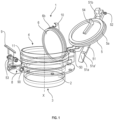
- a drain valve 1 for an aircraft (not shown) is for example shown on the Figure 1 in the open position.
- Valve 1 is typically arranged in an aircraft fuselage.
- Valve 1 is used, for example, to close or open a wastewater tank of the aircraft.
- the valve 1 comprises a cylindrical body 2.
- the body 2 extends along a longitudinal axis X.
- the body 2 is for example made of a metallic material such as stainless steel.
- the body 2 is hollow to allow the circulation of wastewater in the valve 1.
- the body 2 has an orifice inlet 3 and an outlet 4.
- the inlet 3 is intended to be in fluid communication with the tank.
- the outlet 4 is intended to be connected to a device for collecting and possibly sucking up (not shown) wastewater.
- the valve 1 further comprises a first valve 5 and a second valve 6.
- the first valve 5 and the second valve 6 are movable in rotation or pivoting between a closed position and an open position.
- the first valve 5 and the second valve 6 open in the same direction.
- the first valve 5 and the second valve 6 open outwards relative to the body 2 of the valve 1.
- the main lever 51 is rotatable about a lever axis 52 arranged on the first end.
- the locking hook 51b cooperates with a locking rod 53 arranged on the cylindrical body 2.
- the locking rod 53 extends perpendicular to the longitudinal axis X and parallel to the first axis 50.
- the locking rod 53 is arranged opposite the first axis 50 relative to the longitudinal axis X.
- the first valve 5 comprises a cam 54 extending in projection on an internal surface of the first valve 5.
- the cam 54 is capable of cooperating with the second valve 6 when closing the first and second valves 5, 6.
- the second valve 6 forms a first sealing barrier for the valve 1.
- the second valve 6 is intended to be in direct contact with the wastewater from the tank.
- the second valve 6 is arranged inside the cylindrical body 2. In the closed position, the second valve 6 is in contact with the wastewater.
- the second valve 6 is advantageously circular.
- the diameter of the second valve 6 is less than the diameter of the first valve 5.
- the second valve 6 comprises a peripheral annular groove in which a second seal 6b is arranged.
- the second valve 6 is movable in rotation or pivoting around a second axis 60.
- the second axis 60 extends parallel to the first axis 50 and is arranged inside the cylindrical body 2.
- the valve 1 advantageously comprises an intermediate space 7 delimited by the first valve 5 and the second valve 6.
- the first valve 5 and the second valve 6 are driven into the closed position simultaneously.
- the first valve 5 is able to come into abutment with the second valve 6 to drive the second valve 6 into the closed position.
- valve 1 comprises a locking mechanism 8 for locking the second valve member 6 in the closed position.
- the locking mechanism 8 comprises a control lever 9 arranged around a third axis 90, an interface 10 arranged on the second valve member 6 and a drive device 11 for rotating the third axis 90.
- the interface 10 has a height measured along the longitudinal axis X equal to the height of the intermediate space 7.
- the interface 10 projects on an external surface of the second valve 6.
- the interface 10 is arranged in the intermediate space 7.
- the interface 10 cooperates with the first valve 5, in particular with the cam 54, when closing the first and second valves 5, 6 in order to facilitate the driving of the second valve 6 by the first valve 5 in the closed position.
- the control lever 9 is rotatable about the third axis 90 between a locking position and an unlocking position.
- the interface 10 In the locking position, the interface 10 is engaged in the drive device 11.
- the interface 10 In the unlocking position, the interface 10 abuts against the drive device 11.
- the control lever 9 is rotatable in a first direction in the locking position and in a second direction opposite to the first direction in the unlocking position.
- the second valve 6 is driven into the closing position, the interface 10 abuts against the drive device 11 defining the unlocking position.
- the interface 10 is supported on the drive device 11.
- the force exerted by the interface 10 on the drive device 11 has the effect of driving the third axis 90 and the control lever 9 in rotation in the second direction.
- the interface 10 is then engaged, that is to say housed in the drive device 10 and no longer exerts force on the drive device 11 which has the effect of driving the third 90 and the control lever 9 in rotation in the first direction in the locked position.
- the control lever 9 extends along an axis parallel to the longitudinal axis X when the second valve 6 is closed and locked. It has one end arranged around the third axis 90 and an opposite free end. Preferably, a seal (not shown) is arranged between the control lever 9 and the third axis 90.
- the third axis 90 extends parallel to the first axis 50 and the second axis 60.
- the third axis 90 is arranged in a wall mounted on the cylindrical body 2, opposite the first axis 50 and the second axis 60 relative to the longitudinal axis X.
- the third axis 90 has a first free end on which the control lever 9 is arranged and a second free end opposite the first free end.
- the drive device 11 comprises a rack.
- the rack extends along an axis perpendicular to the third axis 90 and to the longitudinal axis X.
- the rack comprises a notched body 110 cooperating with the third axis 90 and an end portion 111 capable of cooperating with the interface 10.
- a third seal 112 is arranged between the notched body 110 and the end portion 111.
- the end portion 111 comprises a notch 111a in which the interface 10 is capable of engaging and a free end 111b with which the interface 10 is capable of coming into abutment.
- the free end 111b has a first surface 111b' capable of coming into abutment with a hook 101 of the interface 10 when the second valve 6 is opened.
- the free end 111b further comprises a second surface 111b" capable of coming into abutment with a first complementary surface 100 of the interface 10 when the second valve 6 is closed.
- the hook 101 is also capable of engaging in the notch 111a when the second valve 6 is closed and locked.
- the drive device 11 advantageously comprises a spring 113 arranged on one end of the rack opposite the end portion 111.
- the operator drives the first valve 5 in rotation into the closed position driving the second valve 6 in rotation into the closed position.
- the main lever 51 is then locked in order to lock the first valve 5.
- the interface 10 of the second valve 6 comes into abutment with the free end 111b of the end portion 111 of the rack.
- This has the effect of driving the main body 110 in translation in a plane perpendicular to the longitudinal axis X in a first direction driving the third axis 90 in rotation.
- the control lever 9 is then driven in rotation into the unlocked position, in the first direction.
- the rack is driven in translation in a second direction opposite to the first direction.
- the interface 10 then engages in the notch 111a locking the second valve 6 in the locking position.
- the third axis 90 is rotated by the rack, rotating the control lever 9 into the locking position, in a second direction opposite to the first direction. This can also be carried out by the operator, if the return force is not sufficient, in particular in the event of deposits on the second valve 6.
- the operator actuates the control lever 9 in the first direction to rotate the third axis 90.
- the rack is then driven in translation until the first surface 111b' of the free end 111b of the end portion 111 of the rack comes into abutment against the hook 101 of the interface 10.
- the force exerted on the interface 10 by the rack makes it possible to rotate the second valve 6 to open it.
- the drive device 11 comprises a ring 211 secured to the third axis 90.
- the ring 211 is advantageously arranged on the second end of the third axis 90 opposite the control lever 9.
- the ring 211 and the third axis 90 form, for example, a single-piece body.
- the ring 211 has a surface 212 with which the interface 10 is able to come into abutment when the second valve 6 is closed and a groove 213 in which the interface 10 is able to engage when locking.
- the operator rotates the first valve 5 into the closed position, rotating the second valve 6 into the closed position.
- the main lever 51 is then locked in order to lock the first valve 5.
- the interface 10 of the second valve 6 comes into abutment with the external surface 212 of the ring 211. This has the effect of rotating the ring 211 in a first direction, rotating the third axis 90.
- the control lever 9 is then rotated into the unlocked position, in the first direction.
- the force exerted by the operator allows the interface 10 to engage in the groove 213 of the ring 211, which has the effect of rotating the ring 211 in a second direction opposite to the first direction.
- the interface 10 is then engaged in the groove 213 locking the second valve 6 in the locking position.
- the third axis 90 is simultaneously rotated, rotating the control lever 9 into the locking position, in a second direction opposite to the first direction.
- the operator actuates the control lever 9 in the first direction to rotate the third axis 90.
- the ring 211 is rotated and an internal surface 214 comes into abutment with a complementary surface 400 of the interface 10.
- the force exerted on the interface 10 by the ring 211 makes it possible to rotate the second valve 6 to open it.
- the drive device 11 comprises a first cylinder 311 having a first cylindrical body 311a and a first free end 311b capable of cooperating with the interface 10, and a second cylinder 312 having a second cylindrical body 312a and a second free end 312b capable of cooperating with the interface 10, the third axis 90 being engaged in the first and the second cylindrical body 311a, 312a.
- the second free end 312b is beveled.
- the first cylinder 311 and the second cylinder 312 are advantageously parallel. They further extend along an axis perpendicular to the third axis 90 and to the longitudinal axis X.
- the free end of the third axis 90 comprises a tenon 313.
- the first cylindrical body 311a has a first housing 311c and the second cylindrical body 312a has a second housing 312c, the tenon 313 being engaged in the first and second housings 311c, 312c.
- the operator drives the first valve 5 in rotation into the closed position driving the second valve 6 in rotation into the closed position.
- the main lever 51 is then locked in order to lock the first valve 5.
- the interface 10 of the second valve 6 comes into abutment with the free end 311b of the first cylinder 311. This has the effect of driving the first cylinder 311 in translation in a first direction driving the tenon 313 in rotation in the first and second housing 311c, 312c and thus the third axis 90 in rotation.
- the control lever 9 is then driven in rotation into the unlocking position, in the first direction.
- the force exerted by the operator allows the interface 10 to be inserted between the first cylinder 311 and the second cylinder 312.
- the operator actuates the control lever 9 in the first direction to rotate the third axis 90.
- the tenon 313 is rotated in each housing 311c, 312c. This has the effect of driving the second cylinder 312 in translation.
- the free end 312b of the second cylinder 312 comes into abutment with the interface 10.
- the interface 10 has a free end 500 having a surface of complementary shape to the beveled free end 312b to facilitate cooperation with the free end 312b of the second cylinder 312.
- the force exerted on the interface 10 by the second cylinder 312 makes it possible to drive the second valve 6 in rotation to open it.
- the valve 1 comprises a locking indicator 12 of the second valve 6.
- the locking indicator 12 is arranged on the control lever 9 and on the main lever 51.
- the locking indicator 12 comprises for example a first visual marker 12a arranged on the control lever 9 and a second visual marker 12b arranged on the main lever 51. In the closed and locking position of the second valve 6, the visual markers 12a, 12b are aligned. This makes it possible to reinforce the reliability of the locking of the second valve 6.
- a step (b) of opening the second valve 6 is carried out.
- the opening is done according to the following sub-step: (b1) rotating the control lever 9 in the first direction. This has the effect of driving the drive device 11 and disengaging the interface 10 from the drive device 11. Once the interface 10 is released from the drive device 11, the control lever 9 is driven back in the second direction.
- Step (a') advantageously comprises the sub-step (a1') of driving the first valve 5 and the second valve 6 in rotation by the first valve 5.
- This sub-step is for example carried out by driving the main lever 51 in rotation.
- a sub-step (a2') of locking the first valve 5 is carried out by locking the main lever 51.
- the first valve 5 and the second valve 6 are then closed and locked.
- the control lever 9 is rotatable in two opposite directions indicating the correct locking of the second valve 6. Furthermore, in the event of a deposit preventing the correct closing of the second valve 6 and therefore the return in rotation of the control lever 9 in the second direction, in the locking position, the operator can directly operate the control lever 9 and force the control lever 9 into the locking position. This further improves the reliability of the locking mechanism 8 of the second valve 6.
- control lever 9 is arranged around the third axis 90 and is rotationally integral with the third axis 90.
- the second valve 6 is rotatable between three positions. A first open position. A second unlocked closing position and a third locked closing position.
- the drive device 11 is movable between two states.
- the second valve 6 When the second valve 6 is in the second position, the drive device 11 is in the first state.
- the second valve 6 When the second valve 6 is in the third position, the drive device 11 is in the second state.
- the second valve 6 When the second valve 6 is in the first open position, the drive device 11 is in the second state.
- the interface 10 In the first state of the drive device 11 associated with the second position of the second valve 6, the interface 10 is in abutment against the drive device 11.
- the drive device 11 rotates the third axis 90, rotating the control lever 9, which is integral in rotation with the third axis 90.
- the locking mechanism 8 of the invention is reversible. This allows the opening of the second valve 6.
- the control lever 9 rotates the third axis 90 and drives the drive device 11, which cooperates with the interface 10 to open the second valve 6.
- the drive device 11 cooperates with the third axis 90 and the interface 10. More particularly, in all the exemplary embodiments, the interface 10 comprises a hook 101 capable of engaging in a housing of the drive device 11 when the second valve 6 is in the closed and locked position.
- the housing is formed by the notch 111a.
- the housing is formed by a space 300 delimited by the free ends 311b, 312b of the first and second cylinders 311, 312.
- the free end 311b of the first cylinder 311 is offset radially relative to the free end 312b of the second cylinder 312, thus forming the space 300.
- the drive device 11 comprises the ring 211.
- the ring 211 is housed in the body 2 of the valve 1.
- the ring 211 is integral with the third axis 90 as in the second example of realization shown on the Figure 4 .
- the third axis 90 is therefore housed in the body 2.
- the second surface 214 is perpendicular to the first surface 212.
- the ring 211 further comprises a third internal surface 215 parallel to the second surface 214 and connected to the first surface 212.
- the third internal surface 215 is connected to the second surface 214 by a rounded internal surface 216.
- the hook 101 has a shape complementary to the ring 211.
- the hook 101 comprises the complementary surface 400 to the second surface 214 and a rounded portion 401 complementary to the rounded surface 216.
- the rounded portion 401 projects.
- the rounded portion 401 is housed in the groove 213 in the locking position.
- the hook 101 For closing, the hook 101, and in particular the rounded portion 401, comes into abutment with the first surface 212, which causes the control lever 9 to rotate into its unlocking position.
- the hook 101, and in particular the rounded portion 401 is then housed in the groove 213, which causes the control lever 9 to rotate into its locking position.
- the ring 211 has a pointed end 214' which makes it easier to open the second valve 6 via the interface 10 when the control lever 9 is actuated for its opening.
- the pointed end 214' comes into contact with the complementary surface 400 of the interface 10 making it possible to rotate the second valve 6 for its opening with an effect lever. More particularly, the second surface 214 is connected to an external surface 216 of the ring 211 by an edge forming the pointed end 214'.
- the distance L between the center of the ring 211 and the pointed end 214' and as measured radially relative to the longitudinal axis X is between 2 mm and 5 mm, preferably between 3 mm and 3.5 mm. Such a distance L makes it possible to exert sufficient leverage to force the opening of the second valve 6, for example in the event of deposits, such as ice, preventing the opening of the second valve 6.
Landscapes
- Engineering & Computer Science (AREA)
- Aviation & Aerospace Engineering (AREA)
- Preventing Unauthorised Actuation Of Valves (AREA)
- Mechanically-Actuated Valves (AREA)
- Sliding Valves (AREA)
Claims (6)
- Ablassventil (1) für ein Luftfahrzeug, umfassend:einen zylindrischen Körper (2), der eine Einlassöffnung (3) und eine Auslassöffnung (4) aufweist,eine erste Klappe (5),eine zweite Klappe (6), angeordnet im Inneren des Körpers (2), wobei die erste und die zweite Klappe (5, 6) jeweils zwischen einer geschlossenen Position und einer offenen Position um eine erste Achse (50) und eine zweite Achse (60) herum drehbeweglich sind,einen Verriegelungsmechanismus (8) der zweiten Klappe (6) in der geschlossenen Position, umfassend:- einen Steuerhebel (9), der um eine dritte Achse (90) herum angeordnet ist,- eine auf der zweiten Klappe (6) angeordnete Schnittstelle (10) und- eine Vorrichtung zum Drehantrieb (11) der dritten Achse (90),wobei der Steuerhebel (9) zwischen einer Entriegelungsposition, in der die Schnittstelle (10) gegen die Antriebsvorrichtung (11) in Anlage vorliegt, und einer Verriegelungsposition, in der die Schnittstelle (10) mit der Antriebsvorrichtung (11) in Eingriff vorliegt, mit der dritten Achse (90) drehfest ist, wobei die Antriebsvorrichtung (11) einen mit der dritten Achse (90) fest verbundenen Dichtungsring (211) umfasst und eine Oberfläche (212) aufweist, mit der die Schnittstelle (10) in Anlage kommen kann, und eine Aussparung (213), mit der die Schnittstelle (10) in Eingriff kommen kann, dadurch gekennzeichnet, dass der Dichtungsring (211) ein spitzes Ende (214') umfasst, das bei dem Öffnen der zweiten Klappe (6) mit einer komplementären Oberfläche (400) der Schnittstelle (10) in Anlage kommen kann.
- Ventil nach dem vorstehenden Anspruch, dadurch gekennzeichnet, dass in Bezug auf eine Längsachse (X) des zylindrischen Körpers (2) die dritte Achse (90) in einer an dem zylindrischen Körper (2) des Ventils (1) montierten Wand gegenüber der ersten und zweiten Achse (50, 60) angeordnet ist.
- Ventil nach einem der vorstehenden Ansprüche, dadurch gekennzeichnet, dass es einen Haupthebel (51) umfasst, der sich auf der ersten Klappe (5) erstreckt, der die erste Klappe (5) und die zweite Klappe (6) von der offenen Position in die geschlossene Position antreiben kann.
- Ventil nach einem der vorstehenden Ansprüche, dadurch gekennzeichnet, dass der Dichtungsring (211) eine interne Oberfläche (214) aufweist, die bei dem Öffnen der zweiten Klappe (6) mit der komplementären Oberfläche (400) der Schnittstelle (10) in Anlage kommen kann, wobei die interne Oberfläche (214) mit einer externen Oberfläche (216) des Dichtungsrings (211) durch eine Kante, die das spitze Ende (214') bildet, verbunden ist.
- Ventil nach einem der vorstehenden Ansprüche, dadurch gekennzeichnet, dass der Steuerhebel (9) in der Entriegelungsposition gemäß einer ersten Richtung und in der Verriegelungsposition gemäß einer zweiten Richtung, entgegengesetzt zu der ersten Richtung, beweglich ist.
- Verfahren zur Verriegelung einer zweiten Klappe (6) eines Ventils (1) nach einem der vorstehenden Ansprüche, umfassend die folgenden Schritte:(a') Schließen der zweiten Klappe (6),(b') Drehantreiben des Steuerhebels (9) in die Entriegelungsposition, in der die Schnittstelle (10) gegen die Antriebsvorrichtung (11) in Anlage vorliegt,(c') Drehantreiben des Steuerhebels (9) in die Verriegelungsposition, in der die Schnittstelle (10) mit der Antriebsvorrichtung (11) in Eingriff vorliegt.
Applications Claiming Priority (2)
| Application Number | Priority Date | Filing Date | Title |
|---|---|---|---|
| FR2010536A FR3115343B1 (fr) | 2020-10-15 | 2020-10-15 | Vanne de vidange pour aeronef et procede associe |
| PCT/FR2021/051803 WO2022079398A1 (fr) | 2020-10-15 | 2021-10-15 | Vanne de vidange pour aeronef et procede associe |
Publications (3)
| Publication Number | Publication Date |
|---|---|
| EP4228969A1 EP4228969A1 (de) | 2023-08-23 |
| EP4228969B1 true EP4228969B1 (de) | 2025-06-25 |
| EP4228969B8 EP4228969B8 (de) | 2025-07-16 |
Family
ID=74125405
Family Applications (1)
| Application Number | Title | Priority Date | Filing Date |
|---|---|---|---|
| EP21807176.9A Active EP4228969B8 (de) | 2020-10-15 | 2021-10-15 | Ablassventil für luftfahrzeuge und entsprechendes verfahren |
Country Status (6)
| Country | Link |
|---|---|
| US (1) | US20230406507A1 (de) |
| EP (1) | EP4228969B8 (de) |
| CN (1) | CN116472222B (de) |
| CA (1) | CA3195400A1 (de) |
| FR (1) | FR3115343B1 (de) |
| WO (1) | WO2022079398A1 (de) |
Families Citing this family (1)
| Publication number | Priority date | Publication date | Assignee | Title |
|---|---|---|---|---|
| CN119173317A (zh) * | 2022-05-09 | 2024-12-20 | 百事可乐公司 | 饮料分配器消耗品系统和方法 |
Family Cites Families (11)
| Publication number | Priority date | Publication date | Assignee | Title |
|---|---|---|---|---|
| US4098427A (en) * | 1977-03-17 | 1978-07-04 | Duckworth Jr Milton Donald | Sealing cap assembly for aircraft lavatory drain port |
| FR2561744A1 (fr) * | 1984-03-26 | 1985-09-27 | Soceman | Clapet de vidange notamment pour cuve de water-closet d'avion |
| US4690296A (en) * | 1985-12-09 | 1987-09-01 | Kaiser Aerospace & Electronics Corporation | Open flow valve assembly |
| US5237709A (en) * | 1989-05-19 | 1993-08-24 | Ta Mfg. Co. | Apparatus for providing a controlled flow of waste material from a waste storage tank |
| US5246131A (en) | 1990-10-29 | 1993-09-21 | Shaw Aero Devices, Inc. | Positive lift pin for aircraft drain valve |
| US5197515A (en) * | 1991-06-14 | 1993-03-30 | Pneu-Draulics, Inc. | Aircraft waste system drain valve |
| US5535784A (en) * | 1993-03-25 | 1996-07-16 | Pneu-Draulics, Inc. | Aircraft waste system drain valve |
| US20050166983A1 (en) * | 2004-02-03 | 2005-08-04 | Shaw James R. | Flush mounted waste disposal service panel assembly |
| US9067680B2 (en) * | 2011-09-29 | 2015-06-30 | The Boeing Company | Aircraft outflow valve |
| US9797522B1 (en) * | 2015-04-28 | 2017-10-24 | Scorpion Safety Handles | Foldable handle for manually-operated quarter-turn valves |
| DE102016200206B4 (de) * | 2016-01-11 | 2020-08-13 | Protechna S.A. | Entnahmearmatur für flüssigkeitsbehälter |
-
2020
- 2020-10-15 FR FR2010536A patent/FR3115343B1/fr active Active
-
2021
- 2021-10-15 EP EP21807176.9A patent/EP4228969B8/de active Active
- 2021-10-15 WO PCT/FR2021/051803 patent/WO2022079398A1/fr not_active Ceased
- 2021-10-15 CA CA3195400A patent/CA3195400A1/en active Pending
- 2021-10-15 CN CN202180075808.4A patent/CN116472222B/zh active Active
- 2021-10-15 US US18/248,550 patent/US20230406507A1/en active Pending
Also Published As
| Publication number | Publication date |
|---|---|
| US20230406507A1 (en) | 2023-12-21 |
| EP4228969A1 (de) | 2023-08-23 |
| CA3195400A1 (en) | 2022-04-21 |
| EP4228969B8 (de) | 2025-07-16 |
| WO2022079398A1 (fr) | 2022-04-21 |
| FR3115343A1 (fr) | 2022-04-22 |
| FR3115343B1 (fr) | 2024-10-18 |
| CN116472222A (zh) | 2023-07-21 |
| CN116472222B (zh) | 2026-02-06 |
Similar Documents
| Publication | Publication Date | Title |
|---|---|---|
| EP2699837B1 (de) | Ventil für eine unter druck stehende flüssigkeit, entsprechender behälter und füllverfahren | |
| EP1526319B1 (de) | Vorrichtung zur Befüllung eines Fahrzeuges mit Flüssigem Krafstoff | |
| FR2523255A1 (fr) | Soupape a coulisse | |
| FR2714709A1 (fr) | Accouplement à ouverture d'urgence alimenté par une double vanne à boisseau sphérique à débordement nul. | |
| FR2981386A1 (fr) | Mecanisme de commande a haut niveau de securite pour un dispositif de transfert etanche entre deux volumes clos | |
| EP1454328B1 (de) | Schutzeinrichtung für eine sterile kammer | |
| EP3693653B1 (de) | Liefervorrichtung für ein unter druck stehendes fluid, und speichereinheit für unter druck stehendes fluid, die eine solche vorrichtung umfasst | |
| WO2013026975A1 (fr) | Dispositif de verrouillage à détection mécanique de fermeture et ouverture | |
| EP4228969A1 (de) | Auslassventil für ein flugzeug und zugehöriges verfahren | |
| CA2015663C (fr) | Robinet a tournant spherique | |
| EP2623835A1 (de) | Schnellanschluss und Temperaturkontrollsystem, bei dem dieser Anschluss integriert ist | |
| FR2538498A1 (fr) | Connecteur hydraulique automatique notamment pour appareil immerge | |
| WO2012052659A2 (fr) | Vanne d'isolement commandee a etancheite renforcee. | |
| EP4034803B1 (de) | Verpackungsvorrichtung, anordnung mit einer solchen vorrichtung und einem behälter, deren verwendung und verfahren zum füllen oder entnehmen | |
| EP0466564B1 (de) | Auseinandernehmbarer Behälter, der für einen internen Druck ausgelegt ist | |
| EP4463618B1 (de) | Vorrichtung zur montage auf einem ölreservoir einer flugzeugturbomaschine, zugehörige ölversorgungsanordnung und zugehöriges verfahren zur verwendung | |
| FR2710720A1 (fr) | Tête de remplissage d'un réservoir de carburant de véhicule automobile. | |
| EP1023513B1 (de) | Sicherheitsschloss, insbesondere für aufzugsschachttür | |
| EP0773395B1 (de) | Betätigungsgriff mit geschütztem Riegel für einen Hahn und damit ausgestatteter Hahn | |
| EP2025818B1 (de) | Abdeckanordnung | |
| FR2772455A1 (fr) | Dispositif adaptable en amont d'une vanne ou analogue de dechargement de liquides, a fonctions multiples notamment de verrouillage et controle | |
| EP0985111B1 (de) | Mischmechanismus für eine sanitärarmatur | |
| EP1630101A1 (de) | Vorrichtung zum Befüllen von Aerosolbehältern | |
| FR2900168A1 (fr) | Coupleur pour engin de travaux a deverrouillage mixte | |
| WO2024099603A1 (fr) | Drain muni d'un dispositif de débrayage |
Legal Events
| Date | Code | Title | Description |
|---|---|---|---|
| STAA | Information on the status of an ep patent application or granted ep patent |
Free format text: STATUS: UNKNOWN |
|
| STAA | Information on the status of an ep patent application or granted ep patent |
Free format text: STATUS: THE INTERNATIONAL PUBLICATION HAS BEEN MADE |
|
| PUAI | Public reference made under article 153(3) epc to a published international application that has entered the european phase |
Free format text: ORIGINAL CODE: 0009012 |
|
| STAA | Information on the status of an ep patent application or granted ep patent |
Free format text: STATUS: REQUEST FOR EXAMINATION WAS MADE |
|
| 17P | Request for examination filed |
Effective date: 20230512 |
|
| AK | Designated contracting states |
Kind code of ref document: A1 Designated state(s): AL AT BE BG CH CY CZ DE DK EE ES FI FR GB GR HR HU IE IS IT LI LT LU LV MC MK MT NL NO PL PT RO RS SE SI SK SM TR |
|
| DAV | Request for validation of the european patent (deleted) | ||
| DAX | Request for extension of the european patent (deleted) | ||
| GRAP | Despatch of communication of intention to grant a patent |
Free format text: ORIGINAL CODE: EPIDOSNIGR1 |
|
| STAA | Information on the status of an ep patent application or granted ep patent |
Free format text: STATUS: GRANT OF PATENT IS INTENDED |
|
| INTG | Intention to grant announced |
Effective date: 20250128 |
|
| GRAS | Grant fee paid |
Free format text: ORIGINAL CODE: EPIDOSNIGR3 |
|
| GRAA | (expected) grant |
Free format text: ORIGINAL CODE: 0009210 |
|
| STAA | Information on the status of an ep patent application or granted ep patent |
Free format text: STATUS: THE PATENT HAS BEEN GRANTED |
|
| AK | Designated contracting states |
Kind code of ref document: B1 Designated state(s): AL AT BE BG CH CY CZ DE DK EE ES FI FR GB GR HR HU IE IS IT LI LT LU LV MC MK MT NL NO PL PT RO RS SE SI SK SM TR |
|
| REG | Reference to a national code |
Ref country code: GB Ref legal event code: FG4D Free format text: NOT ENGLISH |
|
| REG | Reference to a national code |
Ref country code: CH Ref legal event code: EP |
|
| RAP2 | Party data changed (patent owner data changed or rights of a patent transferred) |
Owner name: SAFRAN AEROSYSTEMS |
|
| REG | Reference to a national code |
Ref country code: CH Ref legal event code: EP |
|
| REG | Reference to a national code |
Ref country code: IE Ref legal event code: FG4D Free format text: LANGUAGE OF EP DOCUMENT: FRENCH |
|
| REG | Reference to a national code |
Ref country code: DE Ref legal event code: R096 Ref document number: 602021032994 Country of ref document: DE |
|
| PG25 | Lapsed in a contracting state [announced via postgrant information from national office to epo] |
Ref country code: FI Free format text: LAPSE BECAUSE OF FAILURE TO SUBMIT A TRANSLATION OF THE DESCRIPTION OR TO PAY THE FEE WITHIN THE PRESCRIBED TIME-LIMIT Effective date: 20250625 |
|
| REG | Reference to a national code |
Ref country code: LT Ref legal event code: MG9D |
|
| PG25 | Lapsed in a contracting state [announced via postgrant information from national office to epo] |
Ref country code: NO Free format text: LAPSE BECAUSE OF FAILURE TO SUBMIT A TRANSLATION OF THE DESCRIPTION OR TO PAY THE FEE WITHIN THE PRESCRIBED TIME-LIMIT Effective date: 20250925 Ref country code: GR Free format text: LAPSE BECAUSE OF FAILURE TO SUBMIT A TRANSLATION OF THE DESCRIPTION OR TO PAY THE FEE WITHIN THE PRESCRIBED TIME-LIMIT Effective date: 20250926 |
|
| PG25 | Lapsed in a contracting state [announced via postgrant information from national office to epo] |
Ref country code: BG Free format text: LAPSE BECAUSE OF FAILURE TO SUBMIT A TRANSLATION OF THE DESCRIPTION OR TO PAY THE FEE WITHIN THE PRESCRIBED TIME-LIMIT Effective date: 20250625 |
|
| PG25 | Lapsed in a contracting state [announced via postgrant information from national office to epo] |
Ref country code: HR Free format text: LAPSE BECAUSE OF FAILURE TO SUBMIT A TRANSLATION OF THE DESCRIPTION OR TO PAY THE FEE WITHIN THE PRESCRIBED TIME-LIMIT Effective date: 20250625 |
|
| PG25 | Lapsed in a contracting state [announced via postgrant information from national office to epo] |
Ref country code: RS Free format text: LAPSE BECAUSE OF FAILURE TO SUBMIT A TRANSLATION OF THE DESCRIPTION OR TO PAY THE FEE WITHIN THE PRESCRIBED TIME-LIMIT Effective date: 20250925 |
|
| PG25 | Lapsed in a contracting state [announced via postgrant information from national office to epo] |
Ref country code: LV Free format text: LAPSE BECAUSE OF FAILURE TO SUBMIT A TRANSLATION OF THE DESCRIPTION OR TO PAY THE FEE WITHIN THE PRESCRIBED TIME-LIMIT Effective date: 20250625 |
|
| REG | Reference to a national code |
Ref country code: NL Ref legal event code: MP Effective date: 20250625 |
|
| PG25 | Lapsed in a contracting state [announced via postgrant information from national office to epo] |
Ref country code: NL Free format text: LAPSE BECAUSE OF FAILURE TO SUBMIT A TRANSLATION OF THE DESCRIPTION OR TO PAY THE FEE WITHIN THE PRESCRIBED TIME-LIMIT Effective date: 20250625 |
|
| PG25 | Lapsed in a contracting state [announced via postgrant information from national office to epo] |
Ref country code: PT Free format text: LAPSE BECAUSE OF FAILURE TO SUBMIT A TRANSLATION OF THE DESCRIPTION OR TO PAY THE FEE WITHIN THE PRESCRIBED TIME-LIMIT Effective date: 20251027 |
|
| REG | Reference to a national code |
Ref country code: AT Ref legal event code: MK05 Ref document number: 1806247 Country of ref document: AT Kind code of ref document: T Effective date: 20250625 |
|
| PG25 | Lapsed in a contracting state [announced via postgrant information from national office to epo] |
Ref country code: IS Free format text: LAPSE BECAUSE OF FAILURE TO SUBMIT A TRANSLATION OF THE DESCRIPTION OR TO PAY THE FEE WITHIN THE PRESCRIBED TIME-LIMIT Effective date: 20251025 |
|
| PGFP | Annual fee paid to national office [announced via postgrant information from national office to epo] |
Ref country code: DE Payment date: 20251020 Year of fee payment: 5 |
|
| PG25 | Lapsed in a contracting state [announced via postgrant information from national office to epo] |
Ref country code: AT Free format text: LAPSE BECAUSE OF FAILURE TO SUBMIT A TRANSLATION OF THE DESCRIPTION OR TO PAY THE FEE WITHIN THE PRESCRIBED TIME-LIMIT Effective date: 20250625 Ref country code: SM Free format text: LAPSE BECAUSE OF FAILURE TO SUBMIT A TRANSLATION OF THE DESCRIPTION OR TO PAY THE FEE WITHIN THE PRESCRIBED TIME-LIMIT Effective date: 20250625 |
|
| PGFP | Annual fee paid to national office [announced via postgrant information from national office to epo] |
Ref country code: FR Payment date: 20251023 Year of fee payment: 5 |
|
| PG25 | Lapsed in a contracting state [announced via postgrant information from national office to epo] |
Ref country code: CZ Free format text: LAPSE BECAUSE OF FAILURE TO SUBMIT A TRANSLATION OF THE DESCRIPTION OR TO PAY THE FEE WITHIN THE PRESCRIBED TIME-LIMIT Effective date: 20250625 |
|
| PG25 | Lapsed in a contracting state [announced via postgrant information from national office to epo] |
Ref country code: PL Free format text: LAPSE BECAUSE OF FAILURE TO SUBMIT A TRANSLATION OF THE DESCRIPTION OR TO PAY THE FEE WITHIN THE PRESCRIBED TIME-LIMIT Effective date: 20250625 |
|
| PG25 | Lapsed in a contracting state [announced via postgrant information from national office to epo] |
Ref country code: SK Free format text: LAPSE BECAUSE OF FAILURE TO SUBMIT A TRANSLATION OF THE DESCRIPTION OR TO PAY THE FEE WITHIN THE PRESCRIBED TIME-LIMIT Effective date: 20250625 |
|
| PG25 | Lapsed in a contracting state [announced via postgrant information from national office to epo] |
Ref country code: ES Free format text: LAPSE BECAUSE OF FAILURE TO SUBMIT A TRANSLATION OF THE DESCRIPTION OR TO PAY THE FEE WITHIN THE PRESCRIBED TIME-LIMIT Effective date: 20250625 |
|
| PG25 | Lapsed in a contracting state [announced via postgrant information from national office to epo] |
Ref country code: RO Free format text: LAPSE BECAUSE OF FAILURE TO SUBMIT A TRANSLATION OF THE DESCRIPTION OR TO PAY THE FEE WITHIN THE PRESCRIBED TIME-LIMIT Effective date: 20250625 |
|
| PG25 | Lapsed in a contracting state [announced via postgrant information from national office to epo] |
Ref country code: DK Free format text: LAPSE BECAUSE OF FAILURE TO SUBMIT A TRANSLATION OF THE DESCRIPTION OR TO PAY THE FEE WITHIN THE PRESCRIBED TIME-LIMIT Effective date: 20250625 |
|
| PG25 | Lapsed in a contracting state [announced via postgrant information from national office to epo] |
Ref country code: IT Free format text: LAPSE BECAUSE OF FAILURE TO SUBMIT A TRANSLATION OF THE DESCRIPTION OR TO PAY THE FEE WITHIN THE PRESCRIBED TIME-LIMIT Effective date: 20250625 |
|
| PLBE | No opposition filed within time limit |
Free format text: ORIGINAL CODE: 0009261 |
|
| STAA | Information on the status of an ep patent application or granted ep patent |
Free format text: STATUS: NO OPPOSITION FILED WITHIN TIME LIMIT |
|
| REG | Reference to a national code |
Ref country code: CH Ref legal event code: L10 Free format text: ST27 STATUS EVENT CODE: U-0-0-L10-L00 (AS PROVIDED BY THE NATIONAL OFFICE) Effective date: 20260507 |