EP0466564B1 - Auseinandernehmbarer Behälter, der für einen internen Druck ausgelegt ist - Google Patents
Auseinandernehmbarer Behälter, der für einen internen Druck ausgelegt ist Download PDFInfo
- Publication number
- EP0466564B1 EP0466564B1 EP91401872A EP91401872A EP0466564B1 EP 0466564 B1 EP0466564 B1 EP 0466564B1 EP 91401872 A EP91401872 A EP 91401872A EP 91401872 A EP91401872 A EP 91401872A EP 0466564 B1 EP0466564 B1 EP 0466564B1
- Authority
- EP
- European Patent Office
- Prior art keywords
- container
- cylindrical portion
- shutter
- lid
- movable piece
- Prior art date
- Legal status (The legal status is an assumption and is not a legal conclusion. Google has not performed a legal analysis and makes no representation as to the accuracy of the status listed.)
- Expired - Lifetime
Links
Images

Classifications
-
- F—MECHANICAL ENGINEERING; LIGHTING; HEATING; WEAPONS; BLASTING
- F16—ENGINEERING ELEMENTS AND UNITS; GENERAL MEASURES FOR PRODUCING AND MAINTAINING EFFECTIVE FUNCTIONING OF MACHINES OR INSTALLATIONS; THERMAL INSULATION IN GENERAL
- F16J—PISTONS; CYLINDERS; SEALINGS
- F16J13/00—Covers or similar closure members for pressure vessels in general
- F16J13/24—Covers or similar closure members for pressure vessels in general with safety devices, e.g. to prevent opening prior to pressure release
Definitions
- the present invention relates to a container which can be dismantled in two elements, intended to withstand internal pressure and comprising a first element of which a cylindrical part penetrates into a cylindrical part of a second element, and a seal inserted between these two parts. cylindrical.
- junction line of the two elements of a pressure-resistant, two-part container has a long length
- a connection is often used by parallel flanges between which a seal is interposed.
- This arrangement is safe, but heavy and bulky, and the assembly and disassembly operations of the container are long.
- the container which is for example cylindrical with two possibly curved bottoms, consists of two elements joined in the part of maximum diameter, to facilitate inspections and cleaning for example.
- At least one of the two elements may have closable orifices of smaller diameter for filling or emptying, the obturation of these orifices generally presents less acute problems.
- Removable containers which require the penetration of one cylindrical part (male part) into another (female part) are lighter and less bulky, thanks to the absence of the flanges. Above all, they have the advantage of allowing rapid assembly and disassembly. On the other hand, they present the risk, inherent in rapid disassembly, that this disassembly takes place while the container is still under pressure, which can cause accidents.
- a shut-off valve to the atmosphere has a moving part linked to a valve, and a movable locking member has a surface which moves perpendicular to the axis of the valve and has a cavity capable of receiving the moving part.
- the valve closes, allowing the pressurization, and at the same time the locking member is immobilized by the moving part in a locking position of the cover.
- the valve is kept open, and at the same time the locking member can move.
- This locking member causes a complication, and therefore an increase in cost.
- the object of the present invention is to provide a container provided with a safety device combining the blocking of the cover and the venting, which is simpler to operate and less costly to produce than those of the prior art.
- the sealing means comprises a membrane in the form of an annular disc, the outer edge of which is tightly fixed to the wall of a passage passing through the wall of the container, this passage containing the movable part and the valve. , the inner edge of the membrane constituting a movable sealing ring with play along the movable part and capable of coming, by one face, in sealed contact with the valve or bearing on at least one stop, this ring being pushed towards the valve or the stop by an elastic means which bears on the body of the container.
- this elastic means is to push, via the sealing ring, the moving part towards the interior of the container, when the internal pressure is low, in order to facilitate the installation or the removal. of the cover.
- the membrane is elastic and constitutes in itself said elastic means.
- the container comprises an additional elastic means which maintains a sealed contact between the sealing means and the valve as long as an opposing force resulting from a voluntary action on the moving part, from an incorrect positioning. of the cover, or of an internal overpressure, does not overcome the force of said additional elastic means.
- the valve is thus kept securely closed when the container is opened, which facilitates a subsequent increase in pressure.
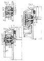
- Figure 1 is an overall view of a container according to the invention.
- FIGS 2, 3 and 4 show in section the locking device respectively in the situation of opening the container, venting and maintaining pressure.
- the device described in the figures is a portable spraying device tank, fitted with a manually actuated pump. It comprises a body 1, provided with a foot 2, and of generally cylindrical shape with a vertical axis.
- a cover 3 has, at its lower part, an inner skirt 4 and an outer skirt 5.
- the inner skirt comes inside the body, the seal being ensured by a seal 6.
- the outer skirt surrounds the upper edge 7 of the body, at a certain distance from it. It carries projections 8 directed radially inwards, and which engage under projections 9 directed radially outwards and carried by the body. All of these projections constitute a quick-lock assembly, of the bayonet type.
- the cover also carries a side handle 10, intended to facilitate the locking of all of the projections, by a rotation of the cover about the vertical axis.
- a handle 11 which controls an interior pump, intended to pressurize the interior of the container, once it is closed.
- Reference 12 designates a valve.
- a side handle 13 integral with the body, and which serves to immobilize the latter while the quick-lock assembly is used.
- the outer skirt has a circular lateral opening 14, through which passes, in the closed position, the control button 15 of a valve device which will now be described in more detail with the aid of FIGS. 2 to 4.
- the safety mechanism is housed, as a whole, inside one of the projections 9 provided on the outer face of the body, near its upper edge. More specifically, the safety mechanism is placed in a radial housing, which passes through the wall of the projection 9 and comprises an enlarged part 16, threaded, on the side of the external wall of the projection 9, and a narrower part 17 located at right the entire upper edge 7 of the body. These two parts are connected by a shoulder 18, radial with respect to the housing.
- a retaining part 19 is screwed into the enlarged part 16, and maintains, between its end 20 and the shoulder 18, the outer edge of an elastic membrane 21, in the form of a roughly flat ring.
- the internal edge of the membrane 21 has an extra thickness, and constitutes a sealing ring 22.
- the valve 23 is a roughly cylindrical part of general shape, which can move along the axis of the radial housing while being guided on one side by an internal flange 24 of the holding part, and on the other side by the wall of the narrower housing part 17.
- This valve comprises an enlarged part 25 in the form of a disc capable of coming to bear on the face of the membrane 21 which is turned towards the inside of the body 1.
- This enlarged part is extended by a rod 26, which passes, with play, through the central opening of the membrane, and carries the control button 15, which projects outwards.
- a rib 27, at the base of the control button, comes to bear on the internal flange 24 of the holding part, to prevent the valve from going out.
- the outer face of the control button 15 has a rounded edge 28 for a reason which will be explained below.
- a helical spring 29 surrounds the rod 26 and bears on the one hand on the control button 15, and on the other hand, on the sealing ring 22, and tends to press the latter against the surface of the projection 25 of the valve, to ensure sealing.
- FIG. 2 shows the situation of the parts of the safety mechanism, in the situation where the cover 3 is removed.
- the inherent elasticity of the membrane 21 keeps it in abutment on the shoulder 18.
- the valve 23 occupies a position where the control button 15 projects outwards from the projection 9 by a small distance e 1 , which is only very little greater than the height of the bevelled part 28.
- Figure 3 shows the situation while the cover 3 has been simply placed on the body 1, without being locked.
- the rounded edge 28 of the button 15 has made it possible to place the cover 3 without being hindered by the button 15. This positioning is further facilitated by the presence of an inclined edge 31 on the outer skirt 5.
- the apparatus is very simple, and nevertheless provides great security.
- the device described alone constitutes double security: on the one hand, it prevents the opening of the container as long as the internal pressure is too high, and on the other hand, it constitutes a safety valve, preventing overpressures .
Landscapes
- Engineering & Computer Science (AREA)
- General Engineering & Computer Science (AREA)
- Mechanical Engineering (AREA)
- Closures For Containers (AREA)
- Pressure Vessels And Lids Thereof (AREA)
Claims (4)
- Behälter mit einem Körper (1), der einen ersten zylindrischen Abschnitt aufweist, und einem Deckel (3), der einen zweiten zylindrischen Abschnitt (5) mit einem Innendurchmesser aufweist, der größer als der Außendurchmesser des ersten zylindrischen Abschnittes des Körpers ist, wobei der Deckel dadurch positioniert wird, daß der zweite zylindrische Abschnitt durch Verschrauben oder in anderer Weise über den ersten zylindrischen Abschnitt bewegt wird, wobei der Behälter ferner eine Sicherheitsvorrichtung aufweist, die versehen ist mit:- einem beweglichen Teil (15), das mit einem Ventilteil (23) fest verbunden ist, welches durch den Innendruck des Behälters in Dichtungsanlage mit einem Abdichtungsmittel (22) geschlossen gehalten wird und welches durch eine von außen kommende Kraft offengehalten werden kann,- einer Außenfläche, die einen Teil des Deckels selbst bildet, wobei der Deckel den zweiten zylindrischen Abschnitt (5) enthält, der senkrecht zu dem Ventilteil (23) beweglich und in der Lage ist, die besagte Kraft auf das bewegliche Teil auszuüben, um das Ventilteil offenzuhalten,- einem Hohlraum (14), der in der besagten Außenfläche vorgesehen ist und in den das bewegliche Teil eindringen kann, wenn es zu dem Hohlraum ausgerichtet ist, wobei das Ventilteil (23) dann in die Schließstellung bewegbar ist,
dadurch gekennzeichnet, daß die besagte Außenfläche von dem Deckel selbst oder dem zweiten zylindrischen Abschnitt (5) gebildet wird und der Hohlraum (14) durch die Wand des Deckels oder des besagten zylindrischen Abschnittes hindurch verläuft. - Behälter nach Anspruch 1, dadurch gekennzeichnet, daß das Abdichtungsmittel eine Membran (21) in Form einer ringförmigen Scheibe aufweist, deren Außenrand abgedichtet an der Wand eines die Behälterwand durchquerenden Kanals (16,17) festgelegt ist, wobei dieser Kanal das bewegliche Teil (15,26) und das Ventilteil (23) enthält, der Innenrand der Membran einen Dichtring (22) bildet, der mit Spiel entlang des beweglichen Teils bewegbar und in der Lage ist, mit einer Stirnfläche in Dichtungsanlage mit einer Fläche des Ventilteils (22) zu kommen oder sich an mindestens einen Anschlag (18) anzulegen, wobei dieser Dichtring in Richtung des Ventilteils oder des Anschlags von einem elastischen Mittel gedrückt wird, das an dem Körper (1) des Behälters anliegt.
- Behälter nach Anspruch 2, dadurch gekennzeichnet, daß die Membran (21) elastisch ist und ihrerseits das elastische Mittel bildet.
- Behälter nach einem der Ansprüche 1 bis 3, dadurch gekennzeichnet, daß er ein zusätzliches elastisches Mittel (29) aufweist, das eine Dichtungsanlage zwischen dem Abdichtungsmittel (22) und dem Ventilteil (23) aufrechterhält, solange eine Gegenkraft, die von einer willkürlichen Einwirkung auf das bewegliche Teil (15), einem fehlerhaften Sitz des Deckels (3) oder einem zu großen Innendruck herrührt, nicht die Kraft des zusätzlichen elastischen Mittels übersteigt.
Applications Claiming Priority (2)
| Application Number | Priority Date | Filing Date | Title |
|---|---|---|---|
| FR9008676 | 1990-07-09 | ||
| FR9008676A FR2664348B1 (fr) | 1990-07-09 | 1990-07-09 | Recipient demontable, pouvant supporter une pression interne. |
Publications (2)
| Publication Number | Publication Date |
|---|---|
| EP0466564A1 EP0466564A1 (de) | 1992-01-15 |
| EP0466564B1 true EP0466564B1 (de) | 1994-09-07 |
Family
ID=9398496
Family Applications (1)
| Application Number | Title | Priority Date | Filing Date |
|---|---|---|---|
| EP91401872A Expired - Lifetime EP0466564B1 (de) | 1990-07-09 | 1991-07-05 | Auseinandernehmbarer Behälter, der für einen internen Druck ausgelegt ist |
Country Status (5)
| Country | Link |
|---|---|
| US (1) | US5176276A (de) |
| EP (1) | EP0466564B1 (de) |
| DE (1) | DE69103838T2 (de) |
| ES (1) | ES2066388T3 (de) |
| FR (1) | FR2664348B1 (de) |
Families Citing this family (7)
| Publication number | Priority date | Publication date | Assignee | Title |
|---|---|---|---|---|
| US5687870A (en) * | 1996-03-04 | 1997-11-18 | Eastman Kodak Company | Pressure lock assembly and pressure vessel |
| US6053541A (en) * | 1998-07-14 | 2000-04-25 | Alliance Laundry Systems Llc | Automatic safety lock-out mechanism for a pressure vessel door |
| EP1215138B1 (de) * | 2000-12-11 | 2004-03-17 | Stöcklin Logistik AG | Container |
| US7600649B1 (en) * | 2005-02-08 | 2009-10-13 | Baker Hughes Incorporated | Methods and devices for preventing extrusion failure of o-ring seal assemblies |
| TWM305811U (en) * | 2006-09-07 | 2007-02-01 | Michilin Prosperity Co Ltd | Coupling mechanism of buckling switch and air release valve of vacuum storage container |
| US9091347B2 (en) * | 2012-01-26 | 2015-07-28 | Halliburton Energy Services, Inc. | Safety cap |
| CA2920185C (en) * | 2013-09-23 | 2019-05-21 | Halliburton Energy Services, Inc. | Threaded safety cap |
Family Cites Families (11)
| Publication number | Priority date | Publication date | Assignee | Title |
|---|---|---|---|---|
| GB874640A (en) * | 1959-01-28 | 1961-08-10 | Geartyht Unions Ltd | Improvements in or relating to closure means for pressure vessels |
| US3135417A (en) * | 1960-05-19 | 1964-06-02 | Bristol Aerojet Ltd | Plugs for pipes and locking means therefor |
| FR1366745A (fr) * | 1962-10-22 | 1964-07-17 | Bochumer Eisen Heintzmann | Perfectionnements apportés aux soupapes, plus spécialement aux soupapes de surpression ou de sûreté pour pressions élevées |
| CH436886A (de) * | 1965-01-22 | 1967-05-31 | Christoff Gerhard Ingenieur | Schnellverschluss für Druckbehälter aller Art, insbesondere für Härtekessel in der Kalksteinindustrie |
| AT328809B (de) * | 1973-11-28 | 1976-04-12 | Oemv Ag | Verschluss fur kreisrunde offnungen mit grossem durchmesser |
| DE7824088U1 (de) * | 1978-08-11 | 1978-11-23 | Carl Prinz Ag, 5650 Solingen | Sicherheitsventil fuer dampfdruckkochtoepfe |
| US4444331A (en) * | 1982-11-08 | 1984-04-24 | Gulf & Western Manufacturing Co. | Closure assembly |
| US4452372A (en) * | 1983-07-08 | 1984-06-05 | Modco Industries, Incorporation | Closure safety device |
| FR2560027B1 (fr) * | 1984-02-29 | 1986-11-14 | Seb Sa | Dispositif de securite a la fermeture et a l'ouverture d'un appareil de cuisson sous pression |
| FR2625979B1 (fr) * | 1988-01-20 | 1990-06-08 | Tecnoma | Recipient demontable, pouvant supporter une pression interne |
| US4840287A (en) * | 1988-04-29 | 1989-06-20 | Henny Penny Corporation | Locking mechanism for a pressure cooker |
-
1990
- 1990-07-09 FR FR9008676A patent/FR2664348B1/fr not_active Expired - Fee Related
-
1991
- 1991-07-05 EP EP91401872A patent/EP0466564B1/de not_active Expired - Lifetime
- 1991-07-05 US US07/726,191 patent/US5176276A/en not_active Expired - Fee Related
- 1991-07-05 ES ES91401872T patent/ES2066388T3/es not_active Expired - Lifetime
- 1991-07-05 DE DE69103838T patent/DE69103838T2/de not_active Expired - Fee Related
Also Published As
| Publication number | Publication date |
|---|---|
| ES2066388T3 (es) | 1995-03-01 |
| DE69103838D1 (de) | 1994-10-13 |
| FR2664348B1 (fr) | 1993-11-05 |
| US5176276A (en) | 1993-01-05 |
| FR2664348A1 (fr) | 1992-01-10 |
| DE69103838T2 (de) | 1995-01-12 |
| EP0466564A1 (de) | 1992-01-15 |
Similar Documents
| Publication | Publication Date | Title |
|---|---|---|
| EP3238580B1 (de) | Schnellkochtopf, der mit einer öffnung im deckel ausgestattet ist | |
| EP0631482B1 (de) | Automatische betätigungsvorrichtung für ein durchflussregelventil | |
| EP0156669B1 (de) | Dampfdruckkochtopf mit Sicherheitsverriegelung des Deckels | |
| EP1032295A1 (de) | Vorrichtung zum verriegeln/entriegeln eines dampfdruck-kochtopfs mit bajonettverschluss | |
| WO2000018279A1 (fr) | Dispositif de securite a l'ouverture d'un appareil de cuisson sous pression a fermeture a baionnettes | |
| EP1547497B1 (de) | Haushaltsdampfdruckkochgerät mit verbesserter Verriegelungsvorrichtung | |
| EP0466564B1 (de) | Auseinandernehmbarer Behälter, der für einen internen Druck ausgelegt ist | |
| WO1998009558A1 (fr) | Appareil a infusion | |
| FR2502591A1 (fr) | Assemblage de liaison pour systemes a deux composantes | |
| EP1568301B1 (de) | Haushaltsdampfdruckkochgerät für Nahrung mit Öffnungssicherheitssystem | |
| EP0879191B1 (de) | Vorrichtung zum dosieren eines fliessfähigen mediums in einem hermetisch geschlossenen behälter | |
| EP3972929A1 (de) | Getränkespender | |
| EP0722689A1 (de) | Sicherheitsdeckel für Kochgefäss | |
| FR2692559A1 (fr) | Dispositif de sécurité pour récipient de conditionnement muni d'un organe de distribution comportant une tige de manÓoeuvre. | |
| EP0522426B1 (de) | Verschluss einer mit einer Sicherung versehenen Öffnung, insbesondere zum Schliessen einer Öffnung eines Behälters für Chemie-, Öl- oder dergleichen Produkte | |
| EP0645274A1 (de) | Füllkopf für einen Kraftstofftank eines Fahrzeuges | |
| FR2702194A1 (fr) | Dispositif de fermeture destiné à un tube à presser. | |
| EP0188156B1 (de) | Überdruckanzeigevorrichtung | |
| EP1027278B1 (de) | Abgabeventil für flüssigkeiten | |
| WO2005089880A1 (fr) | Extincteur portatif | |
| CA3172189A1 (fr) | Dispositif de conditionnement et de distribution de produit avec securite enfant | |
| EP0816721A1 (de) | Abgedicheter Verschlussdeckel | |
| FR3114306A1 (fr) | Capuchon de sécurité pour dispositif de conditionnement de produits pharmaceutiques | |
| FR2655667A1 (fr) | Dispositif d'injection d'eau pour fer a repasser a vapeur et fer a repasser a vapeur comportant un tel dispositif. | |
| FR2616505A1 (fr) | Obturateur pour un orifice perce dans une paroi |
Legal Events
| Date | Code | Title | Description |
|---|---|---|---|
| PUAI | Public reference made under article 153(3) epc to a published international application that has entered the european phase |
Free format text: ORIGINAL CODE: 0009012 |
|
| 17P | Request for examination filed |
Effective date: 19910710 |
|
| AK | Designated contracting states |
Kind code of ref document: A1 Designated state(s): DE ES FR GB IT |
|
| 17Q | First examination report despatched |
Effective date: 19931027 |
|
| GRAA | (expected) grant |
Free format text: ORIGINAL CODE: 0009210 |
|
| AK | Designated contracting states |
Kind code of ref document: B1 Designated state(s): DE ES FR GB IT |
|
| GBT | Gb: translation of ep patent filed (gb section 77(6)(a)/1977) |
Effective date: 19940909 |
|
| REF | Corresponds to: |
Ref document number: 69103838 Country of ref document: DE Date of ref document: 19941013 |
|
| ITF | It: translation for a ep patent filed |
Owner name: STUDIO CONS. BREVETTUALE S.R.L. |
|
| REG | Reference to a national code |
Ref country code: ES Ref legal event code: FG2A Ref document number: 2066388 Country of ref document: ES Kind code of ref document: T3 |
|
| PLBE | No opposition filed within time limit |
Free format text: ORIGINAL CODE: 0009261 |
|
| STAA | Information on the status of an ep patent application or granted ep patent |
Free format text: STATUS: NO OPPOSITION FILED WITHIN TIME LIMIT |
|
| 26N | No opposition filed | ||
| PGFP | Annual fee paid to national office [announced via postgrant information from national office to epo] |
Ref country code: ES Payment date: 20010731 Year of fee payment: 11 |
|
| PGFP | Annual fee paid to national office [announced via postgrant information from national office to epo] |
Ref country code: DE Payment date: 20010827 Year of fee payment: 11 |
|
| REG | Reference to a national code |
Ref country code: GB Ref legal event code: IF02 |
|
| PG25 | Lapsed in a contracting state [announced via postgrant information from national office to epo] |
Ref country code: ES Free format text: LAPSE BECAUSE OF NON-PAYMENT OF DUE FEES Effective date: 20020706 |
|
| PGFP | Annual fee paid to national office [announced via postgrant information from national office to epo] |
Ref country code: GB Payment date: 20020716 Year of fee payment: 12 |
|
| PG25 | Lapsed in a contracting state [announced via postgrant information from national office to epo] |
Ref country code: DE Free format text: LAPSE BECAUSE OF NON-PAYMENT OF DUE FEES Effective date: 20030201 |
|
| PG25 | Lapsed in a contracting state [announced via postgrant information from national office to epo] |
Ref country code: GB Free format text: LAPSE BECAUSE OF NON-PAYMENT OF DUE FEES Effective date: 20030705 |
|
| GBPC | Gb: european patent ceased through non-payment of renewal fee |
Effective date: 20030705 |
|
| REG | Reference to a national code |
Ref country code: ES Ref legal event code: FD2A Effective date: 20030811 |
|
| PG25 | Lapsed in a contracting state [announced via postgrant information from national office to epo] |
Ref country code: IT Free format text: LAPSE BECAUSE OF NON-PAYMENT OF DUE FEES;WARNING: LAPSES OF ITALIAN PATENTS WITH EFFECTIVE DATE BEFORE 2007 MAY HAVE OCCURRED AT ANY TIME BEFORE 2007. THE CORRECT EFFECTIVE DATE MAY BE DIFFERENT FROM THE ONE RECORDED. Effective date: 20050705 |
|
| PGFP | Annual fee paid to national office [announced via postgrant information from national office to epo] |
Ref country code: FR Payment date: 20070530 Year of fee payment: 17 |
|
| REG | Reference to a national code |
Ref country code: FR Ref legal event code: ST Effective date: 20090331 |
|
| PG25 | Lapsed in a contracting state [announced via postgrant information from national office to epo] |
Ref country code: FR Free format text: LAPSE BECAUSE OF NON-PAYMENT OF DUE FEES Effective date: 20080731 |