EP4227652B1 - Flaschenwaage - Google Patents
Flaschenwaage Download PDFInfo
- Publication number
- EP4227652B1 EP4227652B1 EP23156881.7A EP23156881A EP4227652B1 EP 4227652 B1 EP4227652 B1 EP 4227652B1 EP 23156881 A EP23156881 A EP 23156881A EP 4227652 B1 EP4227652 B1 EP 4227652B1
- Authority
- EP
- European Patent Office
- Prior art keywords
- bottle
- feet
- standing
- scale
- contour
- Prior art date
- Legal status (The legal status is an assumption and is not a legal conclusion. Google has not performed a legal analysis and makes no representation as to the accuracy of the status listed.)
- Active
Links
Images


Classifications
-
- G—PHYSICS
- G01—MEASURING; TESTING
- G01G—WEIGHING
- G01G17/00—Apparatus for or methods of weighing material of special form or property
- G01G17/04—Apparatus for or methods of weighing material of special form or property for weighing fluids, e.g. gases, pastes
-
- G—PHYSICS
- G01—MEASURING; TESTING
- G01G—WEIGHING
- G01G21/00—Details of weighing apparatus
- G01G21/28—Frames, Housings
-
- G—PHYSICS
- G01—MEASURING; TESTING
- G01G—WEIGHING
- G01G21/00—Details of weighing apparatus
- G01G21/22—Weigh pans or other weighing receptacles; Weighing platforms
Definitions
- the invention describes a bottle scale, with an upper part on which a support surface for a product to be weighed is formed, and a lower part on which at least one stand is formed, wherein a weight determination takes place by a change in position between the upper part and the lower part.
- Such scales are used, for example, to weigh cylinders, such as refrigerant or gas cylinders. This is done in the field, for example, upon delivery, rather than in a controlled environment. Measurement errors can occur due to stones on the ground or other uneven surfaces.
- the DE 10 2008 040740 B4 describes a food processor with a base part on which a plurality N of feet are arranged for setting up the food processor on a base, and a weighing device, wherein the weighing device has a number M with 0 ⁇ M ⁇ N of weighing modules, characterized in that in order to determine a weight placed on the base part, the center of gravity of the weight to be determined is divided into several center of gravity components, and wherein the center of gravity of the weight to be determined is divided into a center of gravity component of the food processor, a constant center of gravity component of the food to be prepared with the food processor and a dynamic center of gravity component.
- the CN 208 383 263 U describes a weighing device for liquid gas cylinders.
- the object of the invention is to create a bottle scale which is easier to handle, especially in the field.
- the bottle scale according to the invention is characterized in that the installation surface is smaller than the footprint defined by the at least one base. This allows, for example, heavy bottles (approximately 100 kg) to be rolled onto the scale instead of having to lift them with great effort.
- the support feet are located in front of this edge. A force vector acting through the bottle onto the edge is absorbed by the The feet provide additional stability for the scale. This reliably prevents the scale from tipping or slipping.
- At least four feet are provided, each with its own weight sensor. This ensures secure stability.
- the base is formed by a linear connection of the outer edges of adjacent feet. This essentially creates a rectangular or square contour that defines a secure base.
- a vertical projection of the installation surface onto the standing surface lies along the full contour within the standing surface.
- a minimum distance is maintained between one edge of the standing surface and one edge of the installation surface.
- the lower part is at least as large laterally as the upper part, in particular wherein a contour element is formed on the lower part, preferably spaced from a position of a floor defined by the at least one base, which contour element replicates a contour of the upper part at a specific height.
- a contour element is formed on the lower part, preferably spaced from a position of a floor defined by the at least one base, which contour element replicates a contour of the upper part at a specific height.
- the contour element which can be configured, for example, as a rib or protruding edge. Furthermore, the contour element improves use in unpaved terrain. This makes it possible for the contour element to prevent contact with the upper part, even if the support feet sink into soft ground, thus avoiding incorrect measurements.
- a preferably concentric circular segment-shaped contour is formed on the upper part, at least in one segment between two adjacent feet. This makes it easier to center a bottle on the support surface.
- a carrying handle is formed on the upper part, particularly through the circular segment-shaped contour. This allows for easy transport of the scale, for example, without a carrying case.
- a lateral step is arranged in the upper part of the feet. This step is particularly directed toward the installation surface. This makes it easier, in particular, to roll a bottle onto the scale. Furthermore, the step or slope reduces the force vector perpendicular to the floor, thus further reducing the risk of the scale tipping over.
- the lower part and/or the upper part are concave between at least two adjacent feet. This allows, on the one hand, the support surface, at least between the feet, to be smaller than the base area. On the other hand, a step or slope can be placed in this concave area, making it easier to roll a bottle.
- evaluation electronics are located in the upper section. This allows the lower section to be as low as possible, further increasing stability.
- the invention also includes the use of a bottle scale, in particular according to one of the preceding claims, for weighing a fluid-containing bottle, characterized in that the bottle, when positioned centrally, projects laterally beyond a support surface on at least two, in particular four, sides.
- the Fig. 1 shows a bottle scale 1 according to the invention with an upper part 2 and a lower part 3.
- the upper part 2 has a support surface 4 on which a weighing item, in particular a bottle, can be placed.
- the upper part 2 and lower part 3 are movable relative to each other perpendicular to the support surface 4.
- the weight of the weighing object can be determined via the deflection or relative movement.
- a scale electronics (not shown) is arranged in the upper part 2.
- the lower part 3 can be designed very flat.
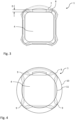
- the Fig. 2 shows a bottom view of the bottle scale 1.
- the bottle scale 1 has four feet 5, whose straight connection of their outer boundaries defines the base 6 of the bottle scale 1.
- the base surface 6 is shown opposite the projection of the support surface 4.
- the contour 7 of the base surface 6 has a distance D to the contour 8 of the support surface 4, which in the example is almost constant over the circumference of the contour.
- the distance D has a minimum distance, which may depend, among other things, on the distances between the feet and/or the height of the scale.
- the distance D can be between 1 cm and 2 cm.
- a contact point or surface between a bottle that is to be rolled onto the scale and the support surface 4 is therefore always within the contour 7 of the base surface 6. This prevents the bottle scale 1 from tipping over if, for example, a bottle is not exactly centered on the support surface 4 or while a bottle is being rolled onto the bottle scale 1.
- the feet 5 have a circular segment-shaped contour 9 on the outside and are arranged so that these circular segments 9 form a first circle 10, as in Fig. 4 shown. Between the feet 5, the bottle scale 1 is concave on three sides 13. In the example, the concave sides 13 are formed by a straight side 18, which is connected to adjacent feet 5 by bevels 14.
- the two circles 10 and 11 are thus clearly visible on the bottle scale 1 and simplify the centering of a round bottle on the support surface 4.
- the bottle scale 1 has a carrying handle 12 on the non-concave side 14, which is convex between two adjacent feet 5 and runs essentially along the first circle 10.
- the carrying handle 12 enables easy picking up and transport of the bottle scale 1, even without an additional carrying case.
- the arrangement of the feet 5 results in an X-shaped configuration of the bottle scale 1. This allows for a significantly larger support surface 4 and thus results in a very stable stand - despite the small design. This is particularly advantageous with heavy bottles and on uneven terrain.
- the Fig. 5 shows a side view of the bottle scale 1.
- the top side 2 of the bottle scale 1 has a bevel 15 or step on each of the concave sides 13 toward the support surface 4. This reduces the obstacle to rolling a bottle onto the scale.
- the underside 3 of the bottle scale 1 has a contour element 16 spaced from the bottom, which replicates a contour of the upper part 2 at a certain height.
- the contour element 16 has the shape of an edge or rib, as shown in Fig. 6 shown in detail.
- the contour element 16 minimizes the risk that the upper part may rest on an uneven floor. This is particularly helpful when used outdoors, as there is insufficient ground clearance there and stones or other objects rest against the upper part 2 and can therefore influence the measurement result. In the embodiment according to the invention, stones and objects rest against this contour element 16. This prevents stones or uneven surfaces from coming into contact with the upper part 2 and thus influencing the measurement result.
- the contour element also improves use on unpaved terrain. This makes it possible for the contour element to prevent contact with the upper part 2 even if the support feet sink into soft ground, thus avoiding incorrect measurements.
Landscapes
- Physics & Mathematics (AREA)
- General Physics & Mathematics (AREA)
- Details Of Rigid Or Semi-Rigid Containers (AREA)
- Containers Having Bodies Formed In One Piece (AREA)
Description
- Die Erfindung beschreibt eine Flaschenwaage, mit einem Oberteil, an welchem eine Aufstellfläche für ein zu wägendes Gut ausgebildet ist, und einem Unterteil, an welchem wenigstens ein Standfuß ausgebildet ist, wobei eine Gewichtsbestimmung durch eine Positionsveränderung zwischen dem Oberteil und dem Unterteil erfolgt.
- Solche Waagen werden beispielsweise benutzt, um Flaschen, beispielsweise Kältemittel- oder Gasflaschen, zu wiegen. Dies erfolgt beispielsweise im Feld, also etwa bei der Anlieferung und nicht in einem kontrollierten Umfeld. Dabei kann es beispielsweise durch Steine am Boden oder andere Unebenheiten zu Messfehlern kommen.
- Die
DE 10 2008 040740 B4 beschreibt eine Küchenmaschine mit einem Basisteil, an welchem eine Mehrzahl N von Füßen zum Aufstellen der Küchenmaschine auf einem Untergrund angeordnet sind, und einer Wägeeinrichtung, wobei die Wägeeinrichtung eine Anzahl M mit 0 < M < N von Wägemodulen aufweist, dadurch gekennzeichnet, dass zur Bestimmung eines in einem auf dem Basisteil aufgestellten Gewichts der Schwerpunkt des zu bestimmenden Gewichts in mehrere Schwerpunktkomponenten unterteilt ist, und wobei der Schwerpunkt des zu bestimmenden Gewichts in eine Schwerpunktkomponente der Küchenmaschine, eine konstante Schwerpunktkomponente des mit der Küchenmaschine zuzubereitenden Zubereitungsguts und eine dynamische Schwerpunktkomponente unterteilt ist. - Die
DE 20 2008 001293 U1 beschreibt eine Vorrichtung zur Kontrolle der Flüssigkeitsentnahme aus einem Flüssigkeitsbehälter zur Überwachung der Flüssigkeitsaufnahme eines Lebewesens über einen Zeitraum, mit - einer Messvorrichtung zur Messung der im Flüssigkeitsbehälter befindlichen Flüssigkeitsmenge,
- einer Zeiterfassungsvorrichtung,
- einem Datenspeicher mit gespeicherten Sollwerten, die jeweils eine Flüssigkeitsmenge repräsentieren,
- einer Auswertevorrichtung, die Istwerte ermittelt, die die entnommene Flüssigkeit über definierte Zeitintervalle repräsentieren, und diese mit den Sollwerten vergleicht,
- einer Signalvorrichtung zur Anzeige des Ergebnisses aus dem Vergleich der Istwerte mit den Sollwerten.
- Die
CN 208 383 263 U beschreibt eine Wiegevorrichtung für Flüssiggasflaschen. - Die Aufgabe der Erfindung ist es eine Flaschenwaage zu schaffen, die eine einfachere Handhabung, insbesondere im Feld, aufweist.
- Diese Aufgabe wird durch eine Flaschenwaage mit den kennzeichnenden Merkmalen des Anspruchs 1 gelöst.
- Demnach ist die erfindungsgemäße Flaschenwaage dadurch gekennzeichnet, dass die Aufstellfläche kleiner als eine durch den wenigstens einen Standfuß definierte Standfläche ist. Auf diese Weise können beispielsweise schwere Flaschen (ca. 100kg) auf die Waage gerollt werden, statt sie unter großer Kraftanstrengung auf die Waage zu heben.
- Beim Rollen der Flasche auf die Waage kommt die Flasche zuerst mit der seitlichen Kante der Waage in Kontakt.
- Dadurch dass die Standfläche größer als die Auflagefläche ist, liegen die Auflagefüßchen vor dieser Kante. Ein Kraftvektor, der durch die Flasche auf die Kante wirkt, wird dabei von den Standfüßen aufgenommen, wodurch der Stand der Waage zusätzlich stabilisiert wird. Ein Kippen oder Verrutschen der Waage wird dadurch sicher verhindert.
- Erfindungsgemäß sind wenigstens vier Standfüße ausgebildet, wobei jeder Standfuß einen eigenen Gewichtssensor hat. Auf diese Weise kann ein sicherer Stand gewährleistet sein.
- Erfindungsgemäß ist die Standfläche durch eine geradlinige Verbindung von äußeren Begrenzungen benachbarter Standfüße gebildet. Dadurch entsteht im Wesentlichen eine rechteckige oder quadratische Kontur, die eine sichere Standfläche definiert.
- Erfindungsgemäß liegt eine senkrechte Projektion der Aufstellfläche auf die Standfläche entlang der vollen Kontur innerhalb der Standfläche. Insbesondere wobei ein Mindestabstand zwischen einem Rand der Standfläche und einem Rand der Aufstellfläche eingehalten ist. Auf diese Weise ist eine einfache Handhabung der Waage möglich, da eine Flasche, wie oben beschrieben, an mehreren Stellen aufgerollt werden kann, ohne dass eine Kippgefahr besteht.
- In einer Ausführung ist das Unterteil in seitlicher Richtung wenigstens so groß wie das Oberteil, insbesondere wobei an dem Unterteil ein vorzugsweise von einer durch den wenigstens einen Standfuß definierten Lage eines Bodens beabstandetes Konturelement ausgebildet ist, welches eine Kontur des Oberteils in einer bestimmten Höhe nachbildet. Auf diese Weise kann das Risiko, dass das Oberteil auf einer Bodenunebenheit aufliegen kann, minimiert oder beseitigt werden. Dies ist insbesondere beim Einsatz im Freien hilfreich, da dort keine ausreichende Bodenfreiheit sichergestellt ist und Steinchen oder andere Gegenstände am Oberteil anliegen und somit das Messergebnis beeinflussen können. Steine oder Unebenheiten können somit nicht mehr die Oberseite berühren und eine Wiegebewegung behindern.
- Bei der erfindungsgemäßen Ausführung liegen Steinchen und Gegenstände stattdessen an dem Konturelement an, das beispielsweise als Rippe oder vorstehende Kante ausgebildet sein kann. Zusätzlich wird durch das Konturelement der Einsatz in unbefestigtem Gelände verbessert. So ist es möglich, dass selbst beim Einsinken der Auflagefüßchen in weichen Boden, durch das Konturelement der Kontakt zum Oberteil verhindert wird und somit Fehlmessungen vermieden werden.
- In einer Ausführung ist an dem Oberteil zumindest in einem Segment zwischen zwei benachbarten Standfüßen eine vorzugsweise konzentrische kreissegmentförmige Kontur gebildet. Auf diese Weise ist es einfacher, eine Flasche auf der Auflagefläche zentriert auszurichten.
- Dadurch ist es beispielsweise trotz einseitigem Blickwinkel möglich zu erkennen, ob die eine Flasche zentrisch positioniert ist, da konzentrische Abweichungen zu den Kreisformen auf der Waage deutlicher auffallen. Beim Heben einer schweren Flasche auf die Waage ist dies besonders hilfreich, da bei dieser Bewegung der Blickwinkel einseitig ist und ein bei marktüblichen Waagen nachträgliches Zentrieren durch Verschieben der Flasche notwendig wird. Hingegen kann bei der erfindungsgemäßen Ausführung eine Flasche bereits bei der Aufsetzbewegung sicher zentriert werden.
- In einer Ausführung ist an dem Oberteil, insbesondere durch die kreissegmentförmige Kontur, ein Tragegriff ausgebildet. Auf diese Weise ist ein einfacher Transport der Waage möglich, beispielsweise ohne Transportkoffer.
- In einer Ausführung ist zwischen wenigstens zwei benachbarten Standfüßen eine seitliche Stufe, insbesondere Abschrägung, in dem Oberteil angeordnet. Diese Stufe ist insbesondere zur Aufstellfläche hin ausgerichtet. Auf diese Weise kann insbesondere das Rollen einer Flasche auf die Waage vereinfacht sein. Darüber hinaus verringert die Stufe oder die Schräge den Kraftvektor senkrecht auf den Boden, so dass eine Kippgefahr der Waage zusätzlich verringert ist.
- In einer Ausführung ist das Unterteil und/oder das Oberteil zwischen wenigstens zwei benachbarten Standfüßen konkav ausgebildet. Dadurch kann einerseits erreicht werden, dass die Auflagefläche zumindest zwischen den Standfüßen kleiner ist als die Standfläche. Zum anderen kann dadurch eine Stufe oder Schrägung in diesem konkaven Bereich liegen wodurch ein Rollen einer Flasche vereinfacht wird.
- In einer Ausführung ist eine Auswerteelektronik im Oberteil angeordnet. Auf diese Weise kann das Unterteil möglichst niedrig ausgebildet sein, wodurch die Standfestigkeit zusätzlich erhöht werden kann.
- Die Erfindung umfasst auch die Verwendung einer Flaschenwaage, insbesondere nach einem der vorangehenden Ansprüche, zum Wägen einer fluidhaltigen Flasche, dadurch gekennzeichnet, dass die Flasche in zentrischer Aufstellung eine Aufstellfläche an wenigstens zwei, insbesondere an vier, Seiten seitlich überragt.
- Die Erfindung ist nachfolgend anhand eines Ausführungsbeispiels mit Bezug auf die beiliegenden Zeichnungen näher erläutert.
- Es zeigt:
- Fig. 1:
- eine Schrägansicht einer erfindungsgemäßen Waage,
- Fig. 2:
- eine Unteransicht der Waage der
Fig. 1 , - Fig. 3:
- eine Seitenansicht der Waage der
Fig. 1 , - Fig. 4:
- eine Detailvergrößerung der
Fig. 4 , - Fig. 5:
- eine Draufsicht der Waage der
Fig. 1 mit eingezeichneten Kreisen, und - Fig. 6:
- die Draufsicht der Waage der
Fig. 1 mit eingezeichneter Auflagefläche und Standfläche. - Die
Fig. 1 zeigt eine erfindungsgemäße Flaschenwaage 1 mit einem Oberteil 2 und einem Unterteil 3. Das Oberteil 2 weist eine Auflagefläche 4 auf, auf das ein Wägegut, insbesondere eine Flasche, abstellbar ist. - Das Oberteil 2 und Unterteil 3 sind relativ zueinander senkrecht zur Auflagefläche 4 beweglich. Über die Auslenkung oder Relativbewegung ist eine Bestimmung der Gewichtskraft des Wägeguts möglich.
- Eine Waageelektronik (nicht gezeigt) ist im Oberteil 2 angeordnet. Auf diese Weise kann das Unterteil 3 sehr flach ausgebildet sein.
- Die
Fig. 2 zeigt eine Unteransicht der Flaschenwaage 1. Die Flaschenwaage 1 besitzt im Beispiel vier Standfüße 5, deren geradlinige Verbindung ihrer äußeren Begrenzungen die Standfläche 6 der Flaschenwaage 1 definieren. InFig. 3 ist die Standfläche 6 gegenüber der Projektion der Auflagefläche 4 gezeigt. Die Kontur 7 der Standfläche 6 weist zur Kontur 8 der Auflagefläche 4 einen Abstand D auf, der im Beispiel über den Umfang der Kontur nahezu konstant ist. Insgesamt kann es vorteilhaft sein, wenn der Abstand D einen Mindestabstand aufweist, der unter anderem von den Abständen zwischen den Standfüßen und/oder der Höhe der Waage abhängen kann. Beispielsweise kann der Abstand D zwischen 1 cm und 2cm betragen. - Eine Kontaktstelle oder -fläche zwischen einer Flasche, die auf die Waage gerollt werden soll, und der Auflagefläche 4 liegt dadurch immer innerhalb der Kontur 7 der Standfläche 6. Dadurch wird verhindert, dass die Flaschenwaage 1 kippt, wenn beispielsweise eine Flasche nicht exakt zentriert auf der Auflagefläche 4 steht oder während eine Flasche auf die Flaschenwaage 1 gerollt wird.
- Die Standfüße 5 weisen nach Außen eine kreissegmentförmige Kontur 9 auf und sind so angeordnet, dass diese Kreissegmente 9 einen ersten Kreis 10 bilden, wie in
Fig. 4 gezeigt. Zwischen den Standfüßen 5 ist die Flaschenwaage 1 an drei Seiten 13 konkav ausgebildet. Im Beispiel sind die konkaven Seiten 13 durch eine gerade Seite 18 gebildet, die durch Schrägen 14 jeweils mit benachbarten Standfüßen 5 verbunden ist. - Die Ecken 17 zwischen den Schrägen 14 und den geraden Seiten 18 bilden zusammen einen zweiten Kreis 11, der konzentrisch innerhalb des ersten Kreises 10 liegt. Die beiden Kreise 10 und 11 sind dadurch deutlich an der Flaschenwaage 1 zu erkennen und vereinfachen eine Zentrierung einer runden Flasche auf der Auflagefläche 4.
- Dadurch ist es möglich, trotz einseitigem Blickwinkel zu erkennen, ob eine runde Flasche zentrisch positioniert auf der Flaschenwaage 1 angeordnet ist, da konzentrische Abweichungen zu den Kreisformen 10, 11 auf der Flaschenwaage 1 deutlicher auffallen, als zu eckigen Strukturen. Beim Heben einer schweren Flasche auf die Flaschenwaage 1 ist dies besonders hilfreich, da bei dieser Bewegung der Blickwinkel einseitig ist und ein bei marktüblichen Waagen nachträgliches Zentrieren durch Verschieben der Flasche notwendig wird. Hingegen kann bei der erfindungsgemäßen Ausführung eine Flasche bereits bei der Aufsetzbewegung sicher zentriert werden.
- Die Flaschenwaage 1 weist an der nicht-konkaven Seite 14 einen Tragegriff 12 auf, der zwischen zwei benachbarten Standfüßen 5 konvex ausgebildet ist und im Wesentlichen entlang des ersten Kreises 10 verläuft. Der Tragegriff 12 ermöglicht eine einfache Aufnahme und einen einfachen Transport der Flaschenwaage 1, auch ohne zusätzlichen Transportkoffer.
- Insgesamt ergibt sich durch die Anordnung der Standfüße 5 eine X-förmige Ausprägung der Flaschenwaage 1. Dies ermöglicht eine deutlich größere Auflagefläche 4 und führt somit - trotz kleiner Bauweise - zu einem sehr stabilen Stand. Dies ist insbesondere bei schweren Flaschen und unebenem Gelände sehr zum Vorteil.
- Die
Fig. 5 zeigt eine Seitenansicht der Flaschenwaage 1. Die Oberseite 2 der Flaschenwaage 1 weist jeweils an den konkaven Seiten 13 zur Auflagefläche 4 hin eine Abschrägung 15 oder Stufe auf. Dadurch verkleinert sich die Hürde zum Rollen einer Flasche auf die Waage. - Die Unterseite 3 der Flaschenwaage 1 weist ein vom Boden beabstandetes Konturelement 16 auf, welches eine Kontur des Oberteils 2 in einer bestimmten Höhe nachbildet. Das Konturelement 16 weist die Form einer Kante oder Rippe auf, wie in
Fig. 6 im Detail gezeigt ist. - Das Konturelement 16 minimiert das Risiko, dass das Oberteil auf einer Bodenunebenheit aufliegen kann. Dies ist insbesondere beim Einsatz im Freien hilfreich, da dort keine ausreichende Bodenfreiheit sichergestellt ist und Steinchen oder andere Gegenstände am Oberteil 2 anliegen, und somit das Messergebnis beeinflussen können. Bei der erfindungsgemäßen Ausführung liegen Steinchen und Gegenstände an diesem Konturelement 16 an. So wird der Kontakt von Steinen oder Unebenheiten zum Oberteil 2 und somit die Beeinflussung vom Messergebnis verhindert. Zusätzlich wird durch das Konturelement der Einsatz in unbefestigtem Gelände verbessert. So ist es möglich, dass selbst bei Einsinken der Auflagefüßchen in weichen Boden über das Konturelement der Kontakt zum Oberteil 2 verhindert wird, und somit Fehlmessungen vermieden werden.
-
- 1
- Waage
- 2
- Oberteil
- 3
- Unterteil
- 4
- Auflagefläche
- 5
- Standfuß
- 6
- Standfläche
- 7
- Kontur der Standfläche
- 8
- Kontur der Auflagefläche
- 9
- Kreissegmente
- 10
- erster Kreis
- 11
- zweiter Kreis
- 12
- Tragegriff
- 14
- Schräge
- 15
- Abschrägung
- 16
- Konturelement
- 17
- Ecke
- 18
- gerade Seite
Claims (7)
- Flaschenwaage, mit einem Oberteil (2), an welchem eine Aufstellfläche (4) für ein zu wägendes Gut ausgebildet ist, und einem Unterteil (3), an welchem wenigstens ein Standfuß (5) ausgebildet ist, wobei eine Gewichtsbestimmung durch eine Positionsveränderung zwischen dem Oberteil (2) und dem Unterteil (3) erfolgt, dadurch gekennzeichnet, dass an dem Unterteil wenigstens vier Standfüße (5) ausgebildet sind, wobei eine Standfläche durch eine geradlinige Verbindung von äußeren Begrenzungen benachbarter Standfüße gebildet ist, wobei jeder Standfuß (5) einen eigenen Gewichtssensor hat, und dass eine senkrechte Projektion der Aufstellfläche auf die Standfläche entlang der vollen Kontur innerhalb der Standfläche liegt.
- Flaschenwaage nach Anspruch 1, dadurch gekennzeichnet, dass das Unterteil (3) in seitlicher Richtung wenigstens so groß ist wie das Oberteil (2), insbesondere wobei an dem Unterteil (3) ein vorzugsweise von einer durch den wenigstens einen Standfuß definierten Lage eines Bodens beabstandetes Konturelement (16) ausgebildet ist, welches eine Kontur des Oberteils (2) in einer bestimmten Höhe nachbildet.
- Flaschenwaage nach einem der vorangehenden Ansprüche, dadurch gekennzeichnet, dass an dem Oberteil (2) zumindest in einem Segment zwischen zwei benachbarten Standfüßen (5) eine vorzugsweise konzentrische kreissegmentförmige Kontur (10, 11) gebildet ist und/oder dass das Unterteil (3) und/oder das Oberteil (2) zwischen wenigstens zwei benachbarten Standfüßen (5) konkav ausgebildet ist.
- Flaschenwaage nach einem der vorangehenden Ansprüche, dadurch gekennzeichnet, dass an dem Oberteil (2), insbesondere durch die kreissegmentförmige Kontur (10), ein Tragegriff (12) ausgebildet ist.
- Flaschenwaage nach einem der vorangehenden Ansprüche, dadurch gekennzeichnet, dass zwischen wenigstens zwei benachbarten Standfüßen (5) seine seitliche Stufe, insbesondere Abschrägung (15), in dem Oberteil (2) angeordnet ist.
- Flaschenwaage nach einem der vorangehenden Ansprüche, dadurch gekennzeichnet, dass eine Auswerteelektronik im Oberteil (2) angeordnet ist.
- Verwendung einer Flaschenwaage nach einem der vorangehenden Ansprüche, zum Wägen einer fluidhaltigen Flasche, dadurch gekennzeichnet, dass die Flasche in zentrischer Aufstellung eine Aufstellfläche an wenigstens zwei, insbesondere an vier, Seiten seitlich überragt.
Applications Claiming Priority (1)
| Application Number | Priority Date | Filing Date | Title |
|---|---|---|---|
| DE102022103557.3A DE102022103557A1 (de) | 2022-02-15 | 2022-02-15 | Flaschenwaage |
Publications (2)
| Publication Number | Publication Date |
|---|---|
| EP4227652A1 EP4227652A1 (de) | 2023-08-16 |
| EP4227652B1 true EP4227652B1 (de) | 2025-04-02 |
Family
ID=80624857
Family Applications (1)
| Application Number | Title | Priority Date | Filing Date |
|---|---|---|---|
| EP23156881.7A Active EP4227652B1 (de) | 2022-02-15 | 2023-02-15 | Flaschenwaage |
Country Status (3)
| Country | Link |
|---|---|
| US (1) | US20230258493A1 (de) |
| EP (1) | EP4227652B1 (de) |
| DE (2) | DE102022103557A1 (de) |
Citations (1)
| Publication number | Priority date | Publication date | Assignee | Title |
|---|---|---|---|---|
| CN208383263U (zh) * | 2018-05-14 | 2019-01-15 | 东莞市剑威电子科技有限公司 | 一种液化气瓶气量显示用称重装置 |
Family Cites Families (3)
| Publication number | Priority date | Publication date | Assignee | Title |
|---|---|---|---|---|
| DE202008001293U1 (de) * | 2007-06-20 | 2008-07-17 | Hasso W. Röttger Distri Care oHG | Vorrichtung zur Kontrolle der Flüssigkeitsentnahme aus einem Trinkgefäß |
| DE102008040740B4 (de) * | 2008-07-25 | 2018-12-27 | BSH Hausgeräte GmbH | Küchenmaschine mit einer Wägeeinrichtung und Verfahren zum Bestimmen eines Gewichts bei einer Küchenmaschine |
| WO2017156619A1 (en) | 2016-03-17 | 2017-09-21 | Apéros Systèmes Inc. | System and method for real-time management of liquid bottles content in a bar or the like |
-
2022
- 2022-02-15 DE DE102022103557.3A patent/DE102022103557A1/de active Pending
- 2022-02-18 DE DE202022100956.2U patent/DE202022100956U1/de active Active
-
2023
- 2023-02-14 US US18/168,742 patent/US20230258493A1/en not_active Abandoned
- 2023-02-15 EP EP23156881.7A patent/EP4227652B1/de active Active
Patent Citations (1)
| Publication number | Priority date | Publication date | Assignee | Title |
|---|---|---|---|---|
| CN208383263U (zh) * | 2018-05-14 | 2019-01-15 | 东莞市剑威电子科技有限公司 | 一种液化气瓶气量显示用称重装置 |
Also Published As
| Publication number | Publication date |
|---|---|
| DE102022103557A1 (de) | 2023-08-17 |
| EP4227652A1 (de) | 2023-08-16 |
| DE202022100956U1 (de) | 2022-02-23 |
| US20230258493A1 (en) | 2023-08-17 |
Similar Documents
| Publication | Publication Date | Title |
|---|---|---|
| EP3845874B1 (de) | Regal | |
| EP1319173A1 (de) | Logistik-waage | |
| EP2178035A1 (de) | Verfahren und Anordnung zur Leerraummessung für Lager- oder Transporträume | |
| EP0371210B1 (de) | Gefässhalter für Präzisionswaagen und Analysenwaagen | |
| DE2801077C2 (de) | ||
| EP3771379B1 (de) | Wägemodulvorrichtung für eine küchenmaschine | |
| DE19548919A1 (de) | Mehrfachüberlastschutz für elektronische Waagen | |
| DE102022103557A1 (de) | Flaschenwaage | |
| DE202017006219U1 (de) | Nivelliervorrichtung | |
| DE9111769U1 (de) | Einfach konstruiertes Instrument zum Messen von Horizontallinien, Vertikallinien und Winkeln | |
| DE10159418A1 (de) | Waagschale und Bestückungs-Plattform für eine Waage sowie Massenkomparator mit einer solchen | |
| DE7302161U (de) | Waage | |
| DE2807041C2 (de) | Vorrichtung zur Gewichtsbestimmung von Flüssigkeiten in Vorratshehältern | |
| DE69309418T2 (de) | Koordinatenmessmaschine | |
| DE2301361C2 (de) | Oberschalige Neigungshebelwaage, insbesondere Tischwaage | |
| EP4101731B1 (de) | Ladungsträger | |
| DE102020008170B4 (de) | Waage, insbesondere Bodenwaage | |
| DE102020008168B4 (de) | Waage, insbesondere Bodenwaage | |
| DE846674C (de) | Flurfoerdergeraet zur Arbeit an Stapeln mit geneigten Flanken | |
| AT226986B (de) | Wiegebrückenlagerung an Waagen | |
| DE3009554A1 (de) | Verfahren zur bestimmung und/oder messung der fuellung von fluessigkeitsgefuellten behaeltern und vorrichtung zur durchfuehrung eines solchen verfahrens | |
| CH698197B1 (de) | Vorrichtung und Verfahren zum Transport eines Wägegutes auf den Lastaufnehmer einer Waage. | |
| EP3118390A1 (de) | Bodenplattenimitat zur verlegung von bodenplatten | |
| DE2656562A1 (de) | Waage, insbesondere fuer den haushaltsgebrauch | |
| DE9207009U1 (de) | Behälter für Lebensmittel wie Marmeladen, Gelees oder Honig |
Legal Events
| Date | Code | Title | Description |
|---|---|---|---|
| PUAI | Public reference made under article 153(3) epc to a published international application that has entered the european phase |
Free format text: ORIGINAL CODE: 0009012 |
|
| STAA | Information on the status of an ep patent application or granted ep patent |
Free format text: STATUS: THE APPLICATION HAS BEEN PUBLISHED |
|
| AK | Designated contracting states |
Kind code of ref document: A1 Designated state(s): AL AT BE BG CH CY CZ DE DK EE ES FI FR GB GR HR HU IE IS IT LI LT LU LV MC ME MK MT NL NO PL PT RO RS SE SI SK SM TR |
|
| STAA | Information on the status of an ep patent application or granted ep patent |
Free format text: STATUS: REQUEST FOR EXAMINATION WAS MADE |
|
| 17P | Request for examination filed |
Effective date: 20240131 |
|
| RBV | Designated contracting states (corrected) |
Designated state(s): AL AT BE BG CH CY CZ DE DK EE ES FI FR GB GR HR HU IE IS IT LI LT LU LV MC ME MK MT NL NO PL PT RO RS SE SI SK SM TR |
|
| STAA | Information on the status of an ep patent application or granted ep patent |
Free format text: STATUS: EXAMINATION IS IN PROGRESS |
|
| 17Q | First examination report despatched |
Effective date: 20240327 |
|
| GRAP | Despatch of communication of intention to grant a patent |
Free format text: ORIGINAL CODE: EPIDOSNIGR1 |
|
| STAA | Information on the status of an ep patent application or granted ep patent |
Free format text: STATUS: GRANT OF PATENT IS INTENDED |
|
| INTG | Intention to grant announced |
Effective date: 20241113 |
|
| GRAS | Grant fee paid |
Free format text: ORIGINAL CODE: EPIDOSNIGR3 |
|
| GRAA | (expected) grant |
Free format text: ORIGINAL CODE: 0009210 |
|
| STAA | Information on the status of an ep patent application or granted ep patent |
Free format text: STATUS: THE PATENT HAS BEEN GRANTED |
|
| AK | Designated contracting states |
Kind code of ref document: B1 Designated state(s): AL AT BE BG CH CY CZ DE DK EE ES FI FR GB GR HR HU IE IS IT LI LT LU LV MC ME MK MT NL NO PL PT RO RS SE SI SK SM TR |
|
| REG | Reference to a national code |
Ref country code: GB Ref legal event code: FG4D Free format text: NOT ENGLISH |
|
| REG | Reference to a national code |
Ref country code: CH Ref legal event code: EP |
|
| REG | Reference to a national code |
Ref country code: DE Ref legal event code: R096 Ref document number: 502023000745 Country of ref document: DE |
|
| REG | Reference to a national code |
Ref country code: IE Ref legal event code: FG4D Free format text: LANGUAGE OF EP DOCUMENT: GERMAN |
|
| REG | Reference to a national code |
Ref country code: NL Ref legal event code: MP Effective date: 20250402 |
|
| PG25 | Lapsed in a contracting state [announced via postgrant information from national office to epo] |
Ref country code: NL Free format text: LAPSE BECAUSE OF FAILURE TO SUBMIT A TRANSLATION OF THE DESCRIPTION OR TO PAY THE FEE WITHIN THE PRESCRIBED TIME-LIMIT Effective date: 20250402 |
|
| PG25 | Lapsed in a contracting state [announced via postgrant information from national office to epo] |
Ref country code: FI Free format text: LAPSE BECAUSE OF FAILURE TO SUBMIT A TRANSLATION OF THE DESCRIPTION OR TO PAY THE FEE WITHIN THE PRESCRIBED TIME-LIMIT Effective date: 20250402 Ref country code: PT Free format text: LAPSE BECAUSE OF FAILURE TO SUBMIT A TRANSLATION OF THE DESCRIPTION OR TO PAY THE FEE WITHIN THE PRESCRIBED TIME-LIMIT Effective date: 20250804 Ref country code: ES Free format text: LAPSE BECAUSE OF FAILURE TO SUBMIT A TRANSLATION OF THE DESCRIPTION OR TO PAY THE FEE WITHIN THE PRESCRIBED TIME-LIMIT Effective date: 20250402 |
|
| REG | Reference to a national code |
Ref country code: LT Ref legal event code: MG9D |
|
| PG25 | Lapsed in a contracting state [announced via postgrant information from national office to epo] |
Ref country code: GR Free format text: LAPSE BECAUSE OF FAILURE TO SUBMIT A TRANSLATION OF THE DESCRIPTION OR TO PAY THE FEE WITHIN THE PRESCRIBED TIME-LIMIT Effective date: 20250703 Ref country code: NO Free format text: LAPSE BECAUSE OF FAILURE TO SUBMIT A TRANSLATION OF THE DESCRIPTION OR TO PAY THE FEE WITHIN THE PRESCRIBED TIME-LIMIT Effective date: 20250702 |
|
| PG25 | Lapsed in a contracting state [announced via postgrant information from national office to epo] |
Ref country code: PL Free format text: LAPSE BECAUSE OF FAILURE TO SUBMIT A TRANSLATION OF THE DESCRIPTION OR TO PAY THE FEE WITHIN THE PRESCRIBED TIME-LIMIT Effective date: 20250402 |
|
| PG25 | Lapsed in a contracting state [announced via postgrant information from national office to epo] |
Ref country code: BG Free format text: LAPSE BECAUSE OF FAILURE TO SUBMIT A TRANSLATION OF THE DESCRIPTION OR TO PAY THE FEE WITHIN THE PRESCRIBED TIME-LIMIT Effective date: 20250402 |
|
| PG25 | Lapsed in a contracting state [announced via postgrant information from national office to epo] |
Ref country code: HR Free format text: LAPSE BECAUSE OF FAILURE TO SUBMIT A TRANSLATION OF THE DESCRIPTION OR TO PAY THE FEE WITHIN THE PRESCRIBED TIME-LIMIT Effective date: 20250402 |
|
| PG25 | Lapsed in a contracting state [announced via postgrant information from national office to epo] |
Ref country code: RS Free format text: LAPSE BECAUSE OF FAILURE TO SUBMIT A TRANSLATION OF THE DESCRIPTION OR TO PAY THE FEE WITHIN THE PRESCRIBED TIME-LIMIT Effective date: 20250702 |
|
| PG25 | Lapsed in a contracting state [announced via postgrant information from national office to epo] |
Ref country code: IS Free format text: LAPSE BECAUSE OF FAILURE TO SUBMIT A TRANSLATION OF THE DESCRIPTION OR TO PAY THE FEE WITHIN THE PRESCRIBED TIME-LIMIT Effective date: 20250802 |
|
| PG25 | Lapsed in a contracting state [announced via postgrant information from national office to epo] |
Ref country code: LV Free format text: LAPSE BECAUSE OF FAILURE TO SUBMIT A TRANSLATION OF THE DESCRIPTION OR TO PAY THE FEE WITHIN THE PRESCRIBED TIME-LIMIT Effective date: 20250402 |
|
| REG | Reference to a national code |
Ref country code: DE Ref legal event code: R097 Ref document number: 502023000745 Country of ref document: DE |
|
| PG25 | Lapsed in a contracting state [announced via postgrant information from national office to epo] |
Ref country code: SM Free format text: LAPSE BECAUSE OF FAILURE TO SUBMIT A TRANSLATION OF THE DESCRIPTION OR TO PAY THE FEE WITHIN THE PRESCRIBED TIME-LIMIT Effective date: 20250402 Ref country code: DK Free format text: LAPSE BECAUSE OF FAILURE TO SUBMIT A TRANSLATION OF THE DESCRIPTION OR TO PAY THE FEE WITHIN THE PRESCRIBED TIME-LIMIT Effective date: 20250402 |
|
| PG25 | Lapsed in a contracting state [announced via postgrant information from national office to epo] |
Ref country code: CZ Free format text: LAPSE BECAUSE OF FAILURE TO SUBMIT A TRANSLATION OF THE DESCRIPTION OR TO PAY THE FEE WITHIN THE PRESCRIBED TIME-LIMIT Effective date: 20250402 |
|
| PG25 | Lapsed in a contracting state [announced via postgrant information from national office to epo] |
Ref country code: EE Free format text: LAPSE BECAUSE OF FAILURE TO SUBMIT A TRANSLATION OF THE DESCRIPTION OR TO PAY THE FEE WITHIN THE PRESCRIBED TIME-LIMIT Effective date: 20250402 |
|
| PG25 | Lapsed in a contracting state [announced via postgrant information from national office to epo] |
Ref country code: SK Free format text: LAPSE BECAUSE OF FAILURE TO SUBMIT A TRANSLATION OF THE DESCRIPTION OR TO PAY THE FEE WITHIN THE PRESCRIBED TIME-LIMIT Effective date: 20250402 |
|
| PG25 | Lapsed in a contracting state [announced via postgrant information from national office to epo] |
Ref country code: IT Free format text: LAPSE BECAUSE OF FAILURE TO SUBMIT A TRANSLATION OF THE DESCRIPTION OR TO PAY THE FEE WITHIN THE PRESCRIBED TIME-LIMIT Effective date: 20250402 |
|
| PLBE | No opposition filed within time limit |
Free format text: ORIGINAL CODE: 0009261 |
|
| STAA | Information on the status of an ep patent application or granted ep patent |
Free format text: STATUS: NO OPPOSITION FILED WITHIN TIME LIMIT |
|
| REG | Reference to a national code |
Ref country code: CH Ref legal event code: L10 Free format text: ST27 STATUS EVENT CODE: U-0-0-L10-L00 (AS PROVIDED BY THE NATIONAL OFFICE) Effective date: 20260211 |
|
| REG | Reference to a national code |
Ref country code: CH Ref legal event code: U11 Free format text: ST27 STATUS EVENT CODE: U-0-0-U10-U11 (AS PROVIDED BY THE NATIONAL OFFICE) Effective date: 20260301 |
|
| 26N | No opposition filed |
Effective date: 20260105 |
|
| PGFP | Annual fee paid to national office [announced via postgrant information from national office to epo] |
Ref country code: DE Payment date: 20260220 Year of fee payment: 4 |
|
| PGFP | Annual fee paid to national office [announced via postgrant information from national office to epo] |
Ref country code: AT Payment date: 20260301 Year of fee payment: 4 |
|
| PGFP | Annual fee paid to national office [announced via postgrant information from national office to epo] |
Ref country code: FR Payment date: 20260227 Year of fee payment: 4 |
|
| PGFP | Annual fee paid to national office [announced via postgrant information from national office to epo] |
Ref country code: CH Payment date: 20260301 Year of fee payment: 4 |
|
| PG25 | Lapsed in a contracting state [announced via postgrant information from national office to epo] |
Ref country code: LT Free format text: LAPSE BECAUSE OF FAILURE TO SUBMIT A TRANSLATION OF THE DESCRIPTION OR TO PAY THE FEE WITHIN THE PRESCRIBED TIME-LIMIT Effective date: 20250402 |
|
| PG25 | Lapsed in a contracting state [announced via postgrant information from national office to epo] |
Ref country code: SE Free format text: LAPSE BECAUSE OF FAILURE TO SUBMIT A TRANSLATION OF THE DESCRIPTION OR TO PAY THE FEE WITHIN THE PRESCRIBED TIME-LIMIT Effective date: 20250402 |