EP4227540B1 - Lagerbarer lüfter - Google Patents
Lagerbarer lüfter Download PDFInfo
- Publication number
- EP4227540B1 EP4227540B1 EP20959397.9A EP20959397A EP4227540B1 EP 4227540 B1 EP4227540 B1 EP 4227540B1 EP 20959397 A EP20959397 A EP 20959397A EP 4227540 B1 EP4227540 B1 EP 4227540B1
- Authority
- EP
- European Patent Office
- Prior art keywords
- rod
- fan
- base
- storable
- support rod
- Prior art date
- Legal status (The legal status is an assumption and is not a legal conclusion. Google has not performed a legal analysis and makes no representation as to the accuracy of the status listed.)
- Active
Links
Images


Classifications
-
- F—MECHANICAL ENGINEERING; LIGHTING; HEATING; WEAPONS; BLASTING
- F04—POSITIVE - DISPLACEMENT MACHINES FOR LIQUIDS; PUMPS FOR LIQUIDS OR ELASTIC FLUIDS
- F04D—NON-POSITIVE-DISPLACEMENT PUMPS
- F04D29/00—Details, component parts, or accessories
- F04D29/60—Mounting; Assembling; Disassembling
- F04D29/601—Mounting; Assembling; Disassembling specially adapted for elastic fluid pumps
-
- F—MECHANICAL ENGINEERING; LIGHTING; HEATING; WEAPONS; BLASTING
- F04—POSITIVE - DISPLACEMENT MACHINES FOR LIQUIDS; PUMPS FOR LIQUIDS OR ELASTIC FLUIDS
- F04D—NON-POSITIVE-DISPLACEMENT PUMPS
- F04D19/00—Axial-flow pumps
- F04D19/002—Axial flow fans
-
- F—MECHANICAL ENGINEERING; LIGHTING; HEATING; WEAPONS; BLASTING
- F04—POSITIVE - DISPLACEMENT MACHINES FOR LIQUIDS; PUMPS FOR LIQUIDS OR ELASTIC FLUIDS
- F04D—NON-POSITIVE-DISPLACEMENT PUMPS
- F04D25/00—Pumping installations or systems
- F04D25/02—Units comprising pumps and their driving means
- F04D25/08—Units comprising pumps and their driving means the working fluid being air, e.g. for ventilation
- F04D25/084—Units comprising pumps and their driving means the working fluid being air, e.g. for ventilation hand fans
-
- F—MECHANICAL ENGINEERING; LIGHTING; HEATING; WEAPONS; BLASTING
- F04—POSITIVE - DISPLACEMENT MACHINES FOR LIQUIDS; PUMPS FOR LIQUIDS OR ELASTIC FLUIDS
- F04D—NON-POSITIVE-DISPLACEMENT PUMPS
- F04D29/00—Details, component parts, or accessories
- F04D29/002—Details, component parts, or accessories especially adapted for elastic fluid pumps
-
- F—MECHANICAL ENGINEERING; LIGHTING; HEATING; WEAPONS; BLASTING
- F04—POSITIVE - DISPLACEMENT MACHINES FOR LIQUIDS; PUMPS FOR LIQUIDS OR ELASTIC FLUIDS
- F04D—NON-POSITIVE-DISPLACEMENT PUMPS
- F04D29/00—Details, component parts, or accessories
- F04D29/40—Casings; Connections of working fluid
- F04D29/52—Casings; Connections of working fluid for axial pumps
- F04D29/522—Casings; Connections of working fluid for axial pumps especially adapted for elastic fluid pumps
-
- F—MECHANICAL ENGINEERING; LIGHTING; HEATING; WEAPONS; BLASTING
- F04—POSITIVE - DISPLACEMENT MACHINES FOR LIQUIDS; PUMPS FOR LIQUIDS OR ELASTIC FLUIDS
- F04D—NON-POSITIVE-DISPLACEMENT PUMPS
- F04D29/00—Details, component parts, or accessories
- F04D29/60—Mounting; Assembling; Disassembling
-
- F—MECHANICAL ENGINEERING; LIGHTING; HEATING; WEAPONS; BLASTING
- F04—POSITIVE - DISPLACEMENT MACHINES FOR LIQUIDS; PUMPS FOR LIQUIDS OR ELASTIC FLUIDS
- F04D—NON-POSITIVE-DISPLACEMENT PUMPS
- F04D29/00—Details, component parts, or accessories
- F04D29/60—Mounting; Assembling; Disassembling
- F04D29/62—Mounting; Assembling; Disassembling of radial or helico-centrifugal pumps
- F04D29/624—Mounting; Assembling; Disassembling of radial or helico-centrifugal pumps especially adapted for elastic fluid pumps
- F04D29/626—Mounting or removal of fans
-
- F—MECHANICAL ENGINEERING; LIGHTING; HEATING; WEAPONS; BLASTING
- F04—POSITIVE - DISPLACEMENT MACHINES FOR LIQUIDS; PUMPS FOR LIQUIDS OR ELASTIC FLUIDS
- F04D—NON-POSITIVE-DISPLACEMENT PUMPS
- F04D29/00—Details, component parts, or accessories
- F04D29/60—Mounting; Assembling; Disassembling
- F04D29/64—Mounting; Assembling; Disassembling of axial pumps
- F04D29/644—Mounting; Assembling; Disassembling of axial pumps especially adapted for elastic fluid pumps
- F04D29/646—Mounting or removal of fans
-
- F—MECHANICAL ENGINEERING; LIGHTING; HEATING; WEAPONS; BLASTING
- F04—POSITIVE - DISPLACEMENT MACHINES FOR LIQUIDS; PUMPS FOR LIQUIDS OR ELASTIC FLUIDS
- F04D—NON-POSITIVE-DISPLACEMENT PUMPS
- F04D29/00—Details, component parts, or accessories
- F04D29/70—Suction grids; Strainers; Dust separation; Cleaning
- F04D29/701—Suction grids; Strainers; Dust separation; Cleaning especially adapted for elastic fluid pumps
- F04D29/703—Suction grids; Strainers; Dust separation; Cleaning especially adapted for elastic fluid pumps specially for fans, e.g. fan guards
-
- F—MECHANICAL ENGINEERING; LIGHTING; HEATING; WEAPONS; BLASTING
- F16—ENGINEERING ELEMENTS AND UNITS; GENERAL MEASURES FOR PRODUCING AND MAINTAINING EFFECTIVE FUNCTIONING OF MACHINES OR INSTALLATIONS; THERMAL INSULATION IN GENERAL
- F16M—FRAMES, CASINGS OR BEDS OF ENGINES, MACHINES OR APPARATUS, NOT SPECIFIC TO ENGINES, MACHINES OR APPARATUS PROVIDED FOR ELSEWHERE; STANDS; SUPPORTS
- F16M11/00—Stands or trestles as supports for apparatus or articles placed thereon ; Stands for scientific apparatus such as gravitational force meters
- F16M11/02—Heads
- F16M11/04—Means for attachment of apparatus; Means allowing adjustment of the apparatus relatively to the stand
- F16M11/06—Means for attachment of apparatus; Means allowing adjustment of the apparatus relatively to the stand allowing pivoting
- F16M11/10—Means for attachment of apparatus; Means allowing adjustment of the apparatus relatively to the stand allowing pivoting around a horizontal axis
-
- F—MECHANICAL ENGINEERING; LIGHTING; HEATING; WEAPONS; BLASTING
- F16—ENGINEERING ELEMENTS AND UNITS; GENERAL MEASURES FOR PRODUCING AND MAINTAINING EFFECTIVE FUNCTIONING OF MACHINES OR INSTALLATIONS; THERMAL INSULATION IN GENERAL
- F16M—FRAMES, CASINGS OR BEDS OF ENGINES, MACHINES OR APPARATUS, NOT SPECIFIC TO ENGINES, MACHINES OR APPARATUS PROVIDED FOR ELSEWHERE; STANDS; SUPPORTS
- F16M11/00—Stands or trestles as supports for apparatus or articles placed thereon ; Stands for scientific apparatus such as gravitational force meters
- F16M11/20—Undercarriages with or without wheels
- F16M11/2007—Undercarriages with or without wheels comprising means allowing pivoting adjustment
- F16M11/2021—Undercarriages with or without wheels comprising means allowing pivoting adjustment around a horizontal axis
-
- F—MECHANICAL ENGINEERING; LIGHTING; HEATING; WEAPONS; BLASTING
- F16—ENGINEERING ELEMENTS AND UNITS; GENERAL MEASURES FOR PRODUCING AND MAINTAINING EFFECTIVE FUNCTIONING OF MACHINES OR INSTALLATIONS; THERMAL INSULATION IN GENERAL
- F16M—FRAMES, CASINGS OR BEDS OF ENGINES, MACHINES OR APPARATUS, NOT SPECIFIC TO ENGINES, MACHINES OR APPARATUS PROVIDED FOR ELSEWHERE; STANDS; SUPPORTS
- F16M11/00—Stands or trestles as supports for apparatus or articles placed thereon ; Stands for scientific apparatus such as gravitational force meters
- F16M11/20—Undercarriages with or without wheels
- F16M11/24—Undercarriages with or without wheels changeable in height or length of legs, also for transport only, e.g. by means of tubes screwed into each other
- F16M11/26—Undercarriages with or without wheels changeable in height or length of legs, also for transport only, e.g. by means of tubes screwed into each other by telescoping, with or without folding
- F16M11/28—Undercarriages for supports with one single telescoping pillar
-
- F—MECHANICAL ENGINEERING; LIGHTING; HEATING; WEAPONS; BLASTING
- F05—INDEXING SCHEMES RELATING TO ENGINES OR PUMPS IN VARIOUS SUBCLASSES OF CLASSES F01-F04
- F05B—INDEXING SCHEME RELATING TO WIND, SPRING, WEIGHT, INERTIA OR LIKE MOTORS, TO MACHINES OR ENGINES FOR LIQUIDS COVERED BY SUBCLASSES F03B, F03D AND F03G
- F05B2210/00—Working fluid
- F05B2210/10—Kind or type
- F05B2210/12—Kind or type gaseous, i.e. compressible
-
- F—MECHANICAL ENGINEERING; LIGHTING; HEATING; WEAPONS; BLASTING
- F05—INDEXING SCHEMES RELATING TO ENGINES OR PUMPS IN VARIOUS SUBCLASSES OF CLASSES F01-F04
- F05D—INDEXING SCHEME FOR ASPECTS RELATING TO NON-POSITIVE-DISPLACEMENT MACHINES OR ENGINES, GAS-TURBINES OR JET-PROPULSION PLANTS
- F05D2210/00—Working fluids
- F05D2210/10—Kind or type
- F05D2210/12—Kind or type gaseous, i.e. compressible
-
- F—MECHANICAL ENGINEERING; LIGHTING; HEATING; WEAPONS; BLASTING
- F05—INDEXING SCHEMES RELATING TO ENGINES OR PUMPS IN VARIOUS SUBCLASSES OF CLASSES F01-F04
- F05D—INDEXING SCHEME FOR ASPECTS RELATING TO NON-POSITIVE-DISPLACEMENT MACHINES OR ENGINES, GAS-TURBINES OR JET-PROPULSION PLANTS
- F05D2260/00—Function
- F05D2260/30—Retaining components in desired mutual position
Definitions
- the present disclosure relates to the technical field of household electrical appliances, and in particular to a storable fan.
- the electric fan As a common household electrical appliance, the electric fan is used frequently.
- the fan is used mostly in summer, but stored in other seasons.
- the conventional fan is hard to store and takes up a large indoor space for its irregular shape.
- the prior fan is wrapped by a guard and placed in the corner.
- the fan is detached into many parts to store in a case. A base and a support arm usually cannot be separated from a fan body until many screws, nuts and so on are detached.
- the utility model publication no. CN207728587U discloses a storage-type floor fan, which comprises a fan head, a telescopic upper rod, a lower rod, and a base; wherein the fan head is connected to the base through the telescopic upper rod and the lower rod; a fan head interface is disposed at a position corresponding to the fan shaft on the fan head; a top of the base is provided with a base interface; and the bottom of the base is provided with a storage space corresponding to the telescopic upper rod and the lower rod.
- the patent application publication no. CN104514733A discloses a floor fan.
- the floor fan comprises a machine head component, a machine body tube component, a chassis component and a chassis connecting piece, wherein the machine head component comprises a machine head and a machine head cover; the machine head cover is fixed in the center of the machine head; a first screwing part is arranged in the center of the machine head cover; the chassis component comprises a chassis body; a central through hole is formed in the chassis body; a groove is formed in the lower surface of the chassis body, and is used for placing the machine body tube component; a second screwing part is arranged on the chassis connecting piece; and the second screwing part of the chassis connecting piece fits the first screwing part of the machine head cover through the central through hole of the chassis body to achieve the purpose of convenient storage.
- the utility model publication no. JPS58191494U discloses a fan.
- a fan head positioned above the base includes a motor and a blast blade, and a column made up of a plurality of unit supports interposed between the base and the fan head and connectable to each other, wherein the height position of the fan head is changed by increasing or decreasing the number of unit supports.
- Two bases are formed in a hollow shape, and a supporting member to which a unit support is detachably supported is provided inside each base.
- the utility model publication no. CN204239295U discloses a fan which comprises a fan head, a vertical column, and a base, wherein the vertical column is detachably connected to the lower portion of the fan head, and the base is detachably connected at the bottom of the vertical column.
- a containing space is defined in the base and is suitable for containing the fan head and the vertical column. According to the fan, the fan head, the vertical column, and the base are detachably connected.
- the containing space is formed in the base, and the fan head and the vertical column can be detached and stored in the containing space of the base when the fan is not used.
- the storage space of the fan is reduced, and the fan can be used as a stool.
- the patent application publication no. CN110285085A discloses a folding storage-type barrel fan.
- the folding storage-type barrel fan comprises a fan head, a telescopic rod body, and a base.
- the fan head is matched with the shape of the base, and the base is provided with a turnover groove and a containing cavity.
- the turnover groove communicates with the containing cavity, and a clamping port is formed in the turnover groove.
- the telescopic rod body comprises a rotating rod, a head rod, and a tail rod, where the tail rod is connected with the rotating rod.
- the bottom part of the rotating rod extends towards the two sides to form convex heads correspondingly.
- the clamping port is connected with the convex heads in a matched mode, and the rotating rod is turned over by taking the convex heads as shafts.
- the fan head is provided with a butt joint part, and the head rod is provided with a rotary head.
- the butt joint part is hinged to the rotary head.
- the telescopic rod body is contracted, and the rotating rod is overturned so that the telescopic rod body can be stored in the turnover groove.
- the fan head is turned over in the direction of the base by taking the rotary head as the axis to enable the fan head to be connected with the base.
- An objective of the present disclosure is to provide a fan structure capable of being stored conveniently, to solve technical problems of a troublesome and complicated storage process, and a large footprint of the fan in the prior art.
- the present invention provides a storable fan, including a fan head, a support rod and a base that are connected detachably, where a first accommodating groove and a second accommodating groove are formed in the base, and the storable fan has a used state and a stored state;
- the fan head includes a guard and a connecting segment rotatably connected to the guard; and a fixing hole is formed in the base;
- the fixing hole and the first accommodating groove are formed in a same side of the base, and the second accommodating groove is formed in the other opposite side of the base.
- the support rod is a telescopic rod.
- the support rod is retracted in the stored state.
- the first end of the support rod connected to the fan head is provided with a first pressing plate, a first engagement member and a first button are provided on the first pressing plate, and a first engagement portion cooperated with the first engagement member is provided on the fan head; and/or the second end of the support rod connected to the base is provided with a second pressing plate, a second engagement member and a second button are provided on the second pressing plate, and a second engagement portion cooperated with the second engagement member is provided on the base.
- an end of the first engagement member away from the second end of the support rod is provided with an outward wedge-shaped surface; and/or an end of the second engagement member away from the first end of the support rod is provided with an outward wedge-shaped surface.
- a first locking piece is provided on the fan head, a second locking piece is provided on the base, and in the stored state, the first locking piece is locked with the second locking piece.
- the first locking piece is a locking rod
- a stationary blocking portion is provided on a surface of the locking rod along the radial direction of the locking rod
- the second locking piece is a locking hole formed in the base
- a movable blocking portion is provided on an inner wall of the locking hole, and the movable blocking portion is extended into the locking hole under an elastic force.
- a third locking piece is provided in the first accommodating groove, and in the stored state, the connecting segment is locked with the third locking piece.
- the support rod includes a first rod and a second rod connected to each other; the first rod is nested in the second rod; a plurality of first grooves are formed in an outer wall of the first rod along the axial direction of the first rod; a control assembly, a limiting hole and a locating pin are provided on the second rod; the locating pin is located in the limiting hole; and the control assembly is configured to limit the locating pin in a locked state of being simultaneously engaged in the first groove and the limiting hole or release the locked state of the locating pin.
- the second rod includes a first wall and a second wall; the first rod is sleeved in the second wall; the control assembly includes a slider and an elastic piece; the slider is slidably provided between the first wall and the second wall; a side of the slider facing the second wall is provided with a second groove; and when the limiting hole directly faces the first groove, the slider limits the locating pin in the limiting hole and the first groove simultaneously under an elastic force of the elastic piece.
- the present disclosure has the following beneficial effects:
- the fan head, the support rod and the base are connected detachably, for ease of detachment of the storable fan.
- Both the fan head and the support rod can be stored in the base.
- the storage process can be accomplished without detaching such fasteners as screws and nuts or by only using few fasteners.
- the storable fan is stored simply and conveniently, with a small footprint.
- the terms “include”, “contain”, and any other variants mean to cover the non-exclusive inclusion, for example, a process, method, system, product, or device that includes a list of steps or units is not necessarily limited to those steps or units which are clearly listed, but may include other steps or units which are not expressly listed or inherent to such a process, method, system, product, or device.
- connection may be a fixed connection, a removable connection, or integration; may be a mechanical connection or an electrical connection; may be a direct connection or an indirect connection implemented by using an intermediate medium; or may be intercommunication between two components, elements or components.
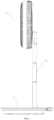
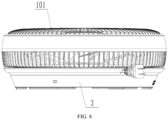
- the present invention provides a storable fan, including fan head 1, support rod 2, and base 3.
- the fan head 1, the support rod 2, and the base 3 are connected detachably.
- First accommodating groove 301 and second accommodating groove 302 are formed in the base 3.
- the storable fan has a used state and a stored state.
- the used state refers to a state in which various components of the fan are assembled for blowing or are ready for blowing.
- the fan head 1, the support rod 2, and the base 3 are connected sequentially.
- the stored state refers to a state in which various components of the fan are arranged for storage.
- the fan head 1 is stored in the first accommodating groove 301.
- the support rod 2 is stored in the second accommodating groove 302.
- the fan head 1, the support rod 2 and the base 3 are connected detachably, for ease of detachment of the storable fan.
- Both the fan head 1 and the support rod 2 can be stored in the base 3.
- the storage process can be accomplished without detaching such fasteners as screws and nuts.
- the storable fan is stored simply and conveniently, with a small footprint.
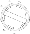
- the first accommodating groove 301 is formed in one side of the base 3.
- the second accommodating groove 302 is formed in the other opposite side of the base 3.
- the first accommodating groove 301 is formed in a top of the base 3.
- the second accommodating groove 302 is formed in a bottom of the base 3.
- the fan head 1 and the support rod 2 can be respectively stored at two sides of the base 3. This makes full use of a space of the base 3, and prevents mutual interference between the fan head 1 and the support rod 2.
- detachable connection between the fan head 1, the support rod 2, and the base 3 is preferably realized by insertion.
- the operation is simple, convenient, and easy-to-realize.
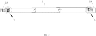
- two ends of the support rod 2 are respectively provided with first insertion portion 218 and second insertion portion 219.
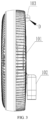
- the fan head 1 includes guard 101 and connecting segment 102 rotatably connected to the guard 101.
- Fixing hole 303 is formed in the base 3.
- the first insertion portion 218 of the support rod 2 is inserted with a connecting portion, while the second insertion portion 219 of the support rod 2 is inserted with the fixing hole 303.
- the connecting segment 102 is fixed in the first accommodating groove 301.
- a shape of the first accommodating groove 301 is matched with a contour of a connecting end.
- the two ends of the support rod 2 may be respectively provided with a corresponding structural component.
- a first end of the support rod 2 connected to the fan head 1, namely the first insertion portion 218, is provided thereon with first pressing plate 201.
- First engagement member 202 and first button 203 are provided on the first pressing plate 201.
- a first engagement portion cooperated with the first engagement member 202 is provided on the fan head 1.
- the first pressing plate 201 can drive the first engagement portion to move inward, thereby generating an acting force opposite to a movement direction.
- the first pressing plate 201 and the first button 203 are restored under the acting force.
- the acting force may be generated by fourth elastic piece 220 between the first pressing plate 201 and the support rod 2.
- the first pressing plate 201 may further be provided as a cantilever structure integrally connected to the support rod 2; and the acting force is generated by deformation of the first pressing plate 201.
- the first button 203 at the end of the support rod 2 is pressed, such that the first pressing plate 201 and the first engagement member 202 move inward.
- the first insertion portion 218 at the end of the support rod 2 is inserted into the connecting segment 102 of the fan head 1.
- the first pressing plate 201 and the first engagement member 202 are restored reversely.
- the first engagement member 202 is engaged with the first engagement portion on the connecting segment 102 of the fan head 1 to realize installation and fixation for the fan head 1 and the support rod 2.
- the first button 203 at the end of the support rod 2 is pressed, such that the first pressing plate 201 and the first engagement member 202 move inward, and the first engagement member 202 is separated from the first engagement portion.
- the first insertion portion 218 at the end of the support rod 2 is moved out of the connecting segment 102 of the fan head 1.
- the first pressing plate 201 and the first engagement member 202 are restored reversely to realize detachment for the fan head 1 and the support rod 2.
- a second end of the support rod 2 connected to the base 3, namely the second insertion portion 219, is provided thereon with second pressing plate 204.
- Second engagement member 205 and second button 206 are provided on the second pressing plate 204.
- a second engagement portion cooperated with the second engagement member 205 is provided in the fixing hole 303 of the base 3.
- the second pressing plate 204 may further be provided as a cantilever structure integrally connected to the support rod 2; and the acting force is generated by deformation of the second pressing plate 204.
- the second button 206 at the end of the support rod 2 is pressed, such that the second pressing plate 204 and the second engagement member 205 move inward.
- the second insertion portion 219 at the end of the support rod 2 is inserted into the fixing hole 303 of the base 3.
- the second pressing plate 204 and the second engagement member 205 are restored reversely.
- the second engagement member 205 is engaged with the second engagement portion in the fixing hole 303 of the base 3 to realize installation and fixation for the base 3 and the support rod 2.
- the second button 206 at the end of the support rod 2 is pressed, such that the second pressing plate 204 and the second engagement member 205 move inward, and the second engagement member 205 is separated from the second engagement portion.
- the second insertion portion 219 at the end of the support rod 2 is moved out of the fixing hole 303 of the base 3.
- the first pressing plate 204 and the first engagement member 205 are restored reversely to realize detachment for the base 3 and the support rod 2.
- an end of the first engagement member 202 away from the second end (the second insertion portion 219) of the support rod 2 is provided with an outward wedge-shaped surface.
- the first button 203 is unnecessarily pressed.
- the connecting segment 102 is interfered with the wedge-shaped surface of the first engagement member 202, and the first engagement member 202 and the first pressing plate 201 are moved inward forcibly.
- the wedge-shaped surface of the first engagement member 202 is released from the connecting segment 102, and the first engagement member moves reversely to engage with the first engagement portion.
- an end of the second engagement member 205 away from the first end (the first insertion portion 218) of the support rod 2 is provided with an outward wedge-shaped surface.
- the wedge-shaped surface of the second engagement member 205 is released from the inner wall of the fixing hole 303, and the second engagement member 205 moves reversely to engage with the second engagement portion.
- the connecting segment 102 of the fan head 1 is attached to the guard 101 by rotating.
- the connecting segment 102 is then placed into the first accommodating groove 301, thereby realizing storage of the fan head 1.
- the guard 101 may rotate relative to the connecting segment 102 to make an overall structure of the fan head 1 and the base 3 unstable.
- a first locking piece is provided on the fan head 1.
- a second locking piece is provided on the base 3.
- the first locking piece is locked with the second locking piece.
- the first locking piece is provided on the guard 101.
- the fan head 1 and the base 3 can further be limited. This prevents the guard 101 from moving relative to the base 3 to make the storage structure unstable.
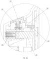
- the first locking piece is locking rod 103.
- Stationary blocking portion 104 is provided on a surface of the locking rod 103 along the radial direction of the locking rod 103.
- the second locking piece is locking hole 311 formed in the base 3.
- Movable blocking portion 304 is provided on an inner wall of the locking hole 311. The movable blocking portion 304 is extended into the locking hole 311 under an elastic force.
- the stationary blocking portion 104 pushes away the movable blocking portion 304 and is inserted under the movable blocking portion.
- the blocking portion is restored under the elastic force to realize engagement between the movable blocking portion 304 and the stationary blocking portion 104, as well as locking between the locking rod 103 and the locking hole 311.
- the locking rod 103 is moved outward by an external force. With the external force, the stationary blocking portion 104 pushes the movable blocking portion 304 forcibly to realize separation between the locking rod 103 and the locking hole 311. More preferably, as shown in FIG. 19 and FIG.
- the movable blocking portion 304 is connected to fourth button 307 through connecting rod 306 rotatably connected to the base 3.
- the fourth button 307 is provided at a side of the base 3.
- First elastic piece 308 is provided between the fourth button 307 and the button 3.
- propping member 309 is provided at a bottom of the locking hole 311.
- the propping member 309 is connected to the base 3 through second elastic piece 310.
- the locking rod 103 abuts against the propping member 309 when entering the locking hole 311 in assembly, so as to overcome an elastic restoring force of the second elastic piece 310.
- the second elastic piece 310 can pop up the fan head 1 automatically through the elastic restoring force. Therefore, the operation is more convenient.
- third locking piece 305 is provided in the first accommodating groove 301.
- the connecting segment 102 is locked with the third locking piece 305 in the stored state, such that a connection strength between the base 3 and the connecting segment 102 can be increased.
- the third locking piece 305 is preferably an elastic gripping jaw structure. An inner wall of the elastic gripping jaw structure is matched with an external contour of the connecting segment 102.
- the elastic gripping jaw structure may be provided at one end of the first accommodating groove 301. During storage, one end of the connecting segment 102 can be inserted into the elastic gripping jaw structure. The first locking piece is then connected to the second locking piece.
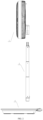
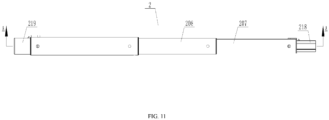
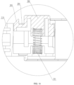
- the support rod 2 is a telescopic rod shown in FIGS. 11-18 .
- the height of the electric fan can be adjusted through the telescopic rod, such that the fan head 1 works at different heights to meet actual requirements of a user.
- the support rod 2 is retracted as shown in FIG. 18 , for better storage of the support rod 2.
- the second accommodating groove 302 in the base 3 is matched with the contour of the support rod 2 in the retracted state.
- the specific structure of the support rod 2 may be various forms of the telescopic rod in the prior art, provided that the objective of the present disclosure can be realized.
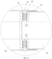
- the support rod 2 includes first rod 207 and second rod 208 connected to each other.
- the first rod 207 is nested in the second rod 208.
- a plurality of first grooves 209 are formed in an outer wall of the first rod 207 along the axial direction of the first rod 207.
- a control assembly, limiting hole 210 and locating pin 211 are provided on the second rod 208.
- the locating pin 211 is located in the limiting hole 210.
- the control assembly is configured to limit the locating pin 211 in a locked state of being simultaneously engaged in the first groove 209 and the limiting hole 210.
- the control assembly is further configured to release the locked state of the locating pin 211.
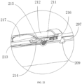
- the second rod 208 includes first wall 212 and second wall 213.
- the first rod 207 is sleeved in the second wall 213.
- the control assembly includes slider 214 and third elastic piece 216.
- the slider 214 is slidably provided between the first wall 212 and the second wall 213.
- a side of the slider 214 facing the second wall 213 is provided with second groove 215.
- the slider 214 When the storable fan is used, the slider 214 is pushed to overcome an elastic restoring force of the third elastic piece 216 to slide in mounting groove 226 between the first wall 212 and the second wall 213. As shown in FIG. 21 , at an extreme position, the second groove 215 in the slider 214 can directly face the limiting hole 210 in the second wall 213. By moving the first rod 207, the outer wall of the first rod 207 pushes the locating pin 211 to move to the second groove 215 of the slider 214. In this case, the first rod 207 and the second rod 208 cannot be locked. When some first groove 209 in the first rod 207 directly faces the limiting hole 210, the locating pin 211 can be located in the limiting hole 210 and the first groove 209 simultaneously.
- the slider 214 is restored under the third elastic piece 216, as shown in FIG. 22 .
- a bottom of the slider 214 abuts against the locating pin 211, the locating pin 211 cannot be released completely from the first groove 209, and the first rod 207 and the second rod 208 are locked through the locating pin 211.
- the slider 214 is pushed, such that the second groove 215 directly faces the limiting hole 210.
- the locating pin 211 is released from the first groove 209 to enter the second groove 215, as shown in FIG. 21 .
- a sum of a thickness of the slider 214 and a diameter of the locating pin 211 is greater than a distance between an inner wall of the first wall 212 and an inner wall of the second wall 213.
- a distance between a bottom of the first groove 209 and the inner wall of the second wall 213 is not less than the diameter of the locating pin 211.
- third button 217 can be provided on the second rod 208. The third button 217 and the slider 214 are in sliding fit through an oblique plane. By pressing the third button 217, the slider 214 can be pushed to slide.
- the third elastic piece 216 pushes the slider 214 to move reversely, thereby pushing the third button 217 for restoration.
- the support rod 2 includes first rod 207 and second rod 208 connected to each other.
- the first rod 207 is nested in the second rod 208.
- Locating hole 222 is formed in a wall of the second rod 208.
- a wall of the first rod 207 is recessed to form an accommodating groove 223.
- Propping bead 224 and sixth elastic piece 225 are provided in the accommodating groove 223.
- the sixth elastic piece 225 is provided between the propping bead 224 and a bottom of the accommodating groove 223. Through the sixth elastic piece 225, the propping bead 224 abuts against an inner wall of the second rod 208 or the locating hole 222.
- a diameter of the locating hole 222 is less than a diameter of the propping bead 224.
- the storable fan according to the above embodiment may further includes other necessary assemblies or structures, and the corresponding arrangement positions and connection relationships may refer to structures of related apparatuses in the prior art.
- the connection relations, operations and working principles of the structures not mentioned above are known to those of ordinary skill in the art, and will not be described in detail herein.
Landscapes
- Engineering & Computer Science (AREA)
- General Engineering & Computer Science (AREA)
- Mechanical Engineering (AREA)
- Structures Of Non-Positive Displacement Pumps (AREA)
Claims (10)
- Klappventilator, umfassend einen Ventilatorkopf (1), eine Halterungsstange (2) und einen Sockel (3), die abnehmbar verbunden sind, wobei eine erste Aufnahmerille (301) und eine zweite Aufnahmerille (302) im Sockel (3) ausgebildet sind und der Klappventilator einen Gebrauchszustand und einen Klappzustand aufweist, wobei der Ventilatorkopf (1), die Halterungsstange (2) und der Sockel (3) nacheinander verbunden sind, wenn sich der Klappventilator im Gebrauchszustand befindet, und der Ventilatorkopf (1) in der ersten Aufnahmerille (301) gelagert ist und die Halterungsstange (2) in der zweiten Aufnahmerille (302) gelagert ist, wenn sich der Klappventilator im Klappzustand befindet,wobei der Ventilatorkopf (1) eine Schutzeinrichtung (101) und ein Verbindungssegment (102), das drehbar mit der Schutzeinrichtung (101) verbunden ist, umfasst und ein Befestigungsloch (303) im Sockel (3) ausgebildet ist, wobei ein erstes Ende und ein zweites Ende der Halterungsstange (2) jeweils mit dem Verbindungssegment (102) und dem Befestigungsloch (303) verbunden sind, wenn sich der Klappventilator im Gebrauchszustand befindet, unddas Befestigungsloch (303) und die erste Aufnahmerille (301) in einer gleichen Seite des Sockels (3) ausgebildet sind und die zweite Aufnahmerille (302) in der anderen gegenüberliegenden Seite des Sockels (3) ausgebildet ist,dadurch gekennzeichnet, dassdas Verbindungssegment (102) in der ersten Aufnahmerille (301) befestigt ist, wenn sich der Klappventilator im Klappzustand befindet.
- Klappventilator nach Anspruch 1, dadurch gekennzeichnet, dass die Halterungsstange (2) eine Teleskopstange ist.
- Klappventilator nach Anspruch 2, dadurch gekennzeichnet, dass die Halterungsstange (2) im Klappzustand eingefahren ist.
- Klappventilator nach Anspruch 1, dadurch gekennzeichnet, dass das erste Ende der Halterungsstange (2), das mit dem Ventilatorkopf (1) verbunden ist, mit einer ersten Andrückplatte (201) versehen ist, ein erstes Eingriffselement (202) und ein erster Knopf (203) auf der ersten Andrückplatte (201) bereitgestellt sind und ein erster Eingriffsabschnitt, der mit dem ersten Eingriffselement (202) kooperiert, auf dem Ventilatorkopf (1) bereitgestellt ist und/oder
das zweite Ende der mit dem Sockel (3) verbundenen Halterungsstange (2) mit einer zweiten Andrückplatte (204) versehen ist, auf der zweiten Andrückplatte (204) ein zweites Eingriffselement (205) und ein zweiter Knopf (206) bereitgestellt sind und ein zweiter Eingriffsabschnitt, der mit dem zweiten Eingriffselement (205) kooperiert, auf dem Sockel (3) bereitgestellt ist. - Klappventilator nach Anspruch 4, dadurch gekennzeichnet, dass ein Ende des ersten Eingriffselements (202), das dem ersten Ende der Halterungsstange (2) zugewandt ist, mit einer nach außen gerichteten keilförmigen Oberfläche versehen ist und/oder
ein Ende des zweiten Eingriffselements (205), das dem zweiten Ende der Halterungsstange (2) zugewandt ist, mit einer nach außen gerichteten keilförmigen Oberfläche versehen ist. - Klappventilator nach Anspruch 1, dadurch gekennzeichnet, dass ein erstes Verriegelungsstück auf dem Ventilatorkopf (1) bereitgestellt ist, ein zweites Verriegelungsstück auf dem Sockel (3) bereitgestellt ist und das erste Verriegelungsstück im Klappzustand mit dem zweiten Verriegelungsstück verriegelt ist.
- Klappventilator nach Anspruch 6, dadurch gekennzeichnet, dass das erste Verriegelungsstück eine Verriegelungsstange (103) ist, ein stationärer Sperrabschnitt (104) auf einer Oberfläche der Verriegelungsstange (103) entlang einer radialen Richtung der Verriegelungsstange (103) bereitgestellt ist, das zweite Verriegelungsstück ein im Sockel (3) ausgebildetes Verriegelungsloch (311) ist, ein beweglicher Sperrabschnitt (304) an einer Innenwand des Verriegelungslochs (311) bereitgestellt ist und der bewegliche Sperrabschnitt (304) unter einer elastischen Kraft in das Verriegelungsloch (311) ausgedehnt wird.
- Klappventilator nach Anspruch 1, dadurch gekennzeichnet, dass ein drittes Verriegelungsstück (305) in der ersten Aufnahmerille (301) bereitgestellt ist und das Verbindungssegment (102) im Klappzustand mit dem dritten Verriegelungsstück (305) verriegelt ist.
- Klappventilator nach Anspruch 2, dadurch gekennzeichnet, dass die Halterungsstange (2) eine erste Stange (207) und eine zweite Stange (208) umfasst, die miteinander verbunden sind, die erste Stange (207) in der zweiten Stange (208) verschachtelt ist, eine Vielzahl von ersten Rillen (209) in einer Außenwand der ersten Stange (207) entlang einer axialen Richtung der ersten Stange (207) ausgebildet ist, eine Steuerbaugruppe, ein Begrenzungsloch (210) und ein Verriegelungsstift (211) auf der zweiten Stange (208) bereitgestellt sind, der Verriegelungsstift (211) sich im Begrenzungsloch (210) befindet und die Steuerbaugruppe ausgelegt ist, um den Verriegelungsstift (211) in einem verriegelten Zustand zu begrenzen, in dem er gleichzeitig in die erste Rille (209) und das Begrenzungsloch (210) eingreift, oder um den verriegelten Zustand des Verriegelungsstifts (211) zu lösen.
- Klappventilator nach Anspruch 9, dadurch gekennzeichnet, dass die zweite Stange (208) eine erste Wand (212) und eine zweite Wand (213) umfasst, die erste Stange (207) in der zweiten Wand (213) ummantelt ist, die Steuerbaugruppe einen Schieber (214) und ein drittes elastisches Stück (216) umfasst, der Schieber (214) verschiebbar zwischen der ersten Wand (212) und der zweiten Wand (213) bereitgestellt ist, eine Seite des Schiebers (214), die der zweiten Wand (213) zugewandt ist, mit einer zweiten Rille (215) versehen ist und der Schieber (214) den Verriegelungsstift (211) im Begrenzungsloch (210) und der ersten Rille (209) gleichzeitig unter einer elastischen Kraft des dritten elastischen Stücks (216) begrenzt, wenn das Begrenzungsloch (210) der ersten Rille (209) direkt zugewandt ist.
Applications Claiming Priority (2)
| Application Number | Priority Date | Filing Date | Title |
|---|---|---|---|
| CN202022456928.4U CN217440321U (zh) | 2020-10-29 | 2020-10-29 | 可收纳风扇 |
| PCT/CN2020/127654 WO2022088237A1 (zh) | 2020-10-29 | 2020-11-10 | 可收纳风扇 |
Publications (4)
| Publication Number | Publication Date |
|---|---|
| EP4227540A1 EP4227540A1 (de) | 2023-08-16 |
| EP4227540A4 EP4227540A4 (de) | 2024-02-21 |
| EP4227540B1 true EP4227540B1 (de) | 2025-01-01 |
| EP4227540C0 EP4227540C0 (de) | 2025-01-01 |
Family
ID=75034955
Family Applications (1)
| Application Number | Title | Priority Date | Filing Date |
|---|---|---|---|
| EP20959397.9A Active EP4227540B1 (de) | 2020-10-29 | 2020-11-10 | Lagerbarer lüfter |
Country Status (5)
| Country | Link |
|---|---|
| US (1) | US11867200B2 (de) |
| EP (1) | EP4227540B1 (de) |
| JP (1) | JP7342107B2 (de) |
| KR (1) | KR102564935B1 (de) |
| CN (1) | CN112567138B (de) |
Families Citing this family (6)
| Publication number | Priority date | Publication date | Assignee | Title |
|---|---|---|---|---|
| CN118793640A (zh) * | 2023-04-14 | 2024-10-18 | 广东美的环境电器制造有限公司 | 风扇 |
| CN118793642A (zh) * | 2023-04-14 | 2024-10-18 | 广东美的环境电器制造有限公司 | 风扇、扇头和风扇的装配方法 |
| US20250160316A1 (en) * | 2023-06-02 | 2025-05-22 | Shenzhen Maichen Suchuang Technology Co., Ltd. | Telescopic insect-and-fly repellent device |
| CN116716714B (zh) * | 2023-07-25 | 2025-08-26 | 珠海格力电器股份有限公司 | 衣杆组件及具有衣杆组件的装置 |
| USD1118886S1 (en) * | 2024-12-16 | 2026-03-17 | Airmate Electrical (Shen Zhen) Co., Ltd | Floor fan |
| USD1105400S1 (en) * | 2025-02-10 | 2025-12-09 | E. Mishan & Sons, Inc. | Folding fan |
Family Cites Families (22)
| Publication number | Priority date | Publication date | Assignee | Title |
|---|---|---|---|---|
| JPS58191494U (ja) * | 1982-06-14 | 1983-12-20 | 株式会社東芝 | 扇風機の高さ調節装置 |
| JPS63158255U (de) * | 1987-04-02 | 1988-10-17 | ||
| JPH0436787Y2 (de) * | 1988-12-27 | 1992-08-31 | ||
| US6139270A (en) * | 1999-02-24 | 2000-10-31 | Liao; Chin-I | Electric fan |
| KR20100124454A (ko) | 2009-05-19 | 2010-11-29 | 이순 | 선풍기 |
| CN101813112A (zh) * | 2010-05-10 | 2010-08-25 | 沈盘根 | 伸缩管 |
| CN201723537U (zh) | 2010-06-13 | 2011-01-26 | 马卫宏 | 伸缩杆 |
| CN104514733B (zh) * | 2013-09-26 | 2017-01-18 | 珠海格力电器股份有限公司 | 落地扇 |
| JP5739038B1 (ja) * | 2013-11-11 | 2015-06-24 | アイリスオーヤマ株式会社 | 扇風機 |
| CN104389820B (zh) | 2014-11-04 | 2017-10-13 | 珠海格力电器股份有限公司 | 立柱连接结构及电风扇 |
| CN204239295U (zh) * | 2014-11-18 | 2015-04-01 | 广东美的环境电器制造有限公司 | 风扇 |
| CN106015041A (zh) * | 2016-06-17 | 2016-10-12 | 杭州飞鱼工业设计有限公司 | 立式电风扇 |
| CN207728587U (zh) * | 2017-12-24 | 2018-08-14 | 江南大学 | 一种收纳式落地扇 |
| US11162513B2 (en) * | 2018-12-20 | 2021-11-02 | Zhejiang Joyo Electric Appliance Technology Co,. Ltd. | Adjustable stand fan |
| CN110469793B (zh) * | 2019-01-25 | 2020-10-27 | 深圳叠品科技有限公司 | 一种新型折叠装置及其运用的风扇和台灯 |
| WO2020151102A1 (zh) | 2019-01-25 | 2020-07-30 | 深圳市全天拍科技有限公司 | 一种可折叠风扇 |
| CN110285085A (zh) * | 2019-07-12 | 2019-09-27 | 中山市春凯电器有限公司 | 一种折叠收纳式筒扇 |
| CN210509656U (zh) | 2019-08-06 | 2020-05-12 | 东莞市格尚电器有限公司 | 可折叠便携式风扇 |
| CN210565256U (zh) | 2019-09-11 | 2020-05-19 | 宋胜强 | 折叠式摇头风扇 |
| CN210949218U (zh) | 2019-11-22 | 2020-07-07 | 佛山市沃尼思通环境电器有限公司 | 一种可折叠风扇 |
| JP3225783U (ja) | 2020-01-22 | 2020-04-02 | 株式会社住本製作所 | ポータブル扇風機 |
| US11378100B2 (en) * | 2020-11-30 | 2022-07-05 | E. Mishan & Sons, Inc. | Oscillating portable fan with removable grille |
-
2020
- 2020-11-10 CN CN202080002845.8A patent/CN112567138B/zh active Active
- 2020-11-10 US US18/250,999 patent/US11867200B2/en active Active
- 2020-11-10 JP JP2021506980A patent/JP7342107B2/ja active Active
- 2020-11-10 KR KR1020217004106A patent/KR102564935B1/ko active Active
- 2020-11-10 EP EP20959397.9A patent/EP4227540B1/de active Active
Also Published As
| Publication number | Publication date |
|---|---|
| US20230392614A1 (en) | 2023-12-07 |
| CN112567138B (zh) | 2022-12-06 |
| EP4227540A4 (de) | 2024-02-21 |
| JP2023503727A (ja) | 2023-02-01 |
| CN112567138A (zh) | 2021-03-26 |
| KR102564935B1 (ko) | 2023-08-08 |
| EP4227540C0 (de) | 2025-01-01 |
| JP7342107B2 (ja) | 2023-09-11 |
| KR20220058834A (ko) | 2022-05-10 |
| EP4227540A1 (de) | 2023-08-16 |
| US11867200B2 (en) | 2024-01-09 |
Similar Documents
| Publication | Publication Date | Title |
|---|---|---|
| EP4227540B1 (de) | Lagerbarer lüfter | |
| CN110230754B (zh) | 一种夹爪隐藏式设计的夹持装置 | |
| CN110652104B (zh) | 多功能安装支架 | |
| CN209051226U (zh) | 一种新型多功能设计用便携画架 | |
| CN217440321U (zh) | 可收纳风扇 | |
| US20100018086A1 (en) | Retractable iron and ironing board assembly | |
| CN114856219A (zh) | 一种预制墙板安装装置 | |
| CN219762669U (zh) | 一种可扩展式收纳箱 | |
| CN210672522U (zh) | 多功能折叠桌 | |
| CN214072346U (zh) | 一种自动锁定的折叠餐桌 | |
| CN215737538U (zh) | 一种桌板可翻转的桌子 | |
| CN222149799U (zh) | 一种提手可收纳的煎烤机 | |
| CN222941953U (zh) | 电脑桌的搁板结构及电脑桌 | |
| CN211625449U (zh) | 安装结构、安装壳体及取暖设备 | |
| CN223195685U (zh) | 简易升降桌 | |
| CN219047745U (zh) | 一种具有旋转面板的储物桌 | |
| CN222941941U (zh) | 可折叠桌板结构及电脑桌 | |
| CN220402156U (zh) | 一种连接组件、电子设备的壳体及电子设备 | |
| CN219422421U (zh) | 一种可安装在墙壁上的折叠桌面 | |
| CN222367790U (zh) | 一种辅助工作台及麻醉机 | |
| CN222367789U (zh) | 一种辅助工作台及麻醉机 | |
| CN219000094U (zh) | 烤炉及活动边台结构 | |
| CN213403107U (zh) | 一种支架组件 | |
| CN220881803U (zh) | 一种研磨刷用的固定架构 | |
| CN117322821A (zh) | 一种清洁工具 |
Legal Events
| Date | Code | Title | Description |
|---|---|---|---|
| STAA | Information on the status of an ep patent application or granted ep patent |
Free format text: STATUS: THE INTERNATIONAL PUBLICATION HAS BEEN MADE |
|
| PUAI | Public reference made under article 153(3) epc to a published international application that has entered the european phase |
Free format text: ORIGINAL CODE: 0009012 |
|
| STAA | Information on the status of an ep patent application or granted ep patent |
Free format text: STATUS: REQUEST FOR EXAMINATION WAS MADE |
|
| 17P | Request for examination filed |
Effective date: 20230510 |
|
| AK | Designated contracting states |
Kind code of ref document: A1 Designated state(s): AL AT BE BG CH CY CZ DE DK EE ES FI FR GB GR HR HU IE IS IT LI LT LU LV MC MK MT NL NO PL PT RO RS SE SI SK SM TR |
|
| DAV | Request for validation of the european patent (deleted) | ||
| DAX | Request for extension of the european patent (deleted) | ||
| A4 | Supplementary search report drawn up and despatched |
Effective date: 20240122 |
|
| RIC1 | Information provided on ipc code assigned before grant |
Ipc: F04D 29/64 20060101ALI20240116BHEP Ipc: F04D 29/60 20060101ALI20240116BHEP Ipc: F04D 19/00 20060101ALI20240116BHEP Ipc: F04D 25/08 20060101AFI20240116BHEP |
|
| GRAP | Despatch of communication of intention to grant a patent |
Free format text: ORIGINAL CODE: EPIDOSNIGR1 |
|
| STAA | Information on the status of an ep patent application or granted ep patent |
Free format text: STATUS: GRANT OF PATENT IS INTENDED |
|
| RIC1 | Information provided on ipc code assigned before grant |
Ipc: F04D 29/64 20060101ALI20240626BHEP Ipc: F04D 29/60 20060101ALI20240626BHEP Ipc: F04D 19/00 20060101ALI20240626BHEP Ipc: F04D 25/08 20060101AFI20240626BHEP |
|
| INTG | Intention to grant announced |
Effective date: 20240717 |
|
| GRAS | Grant fee paid |
Free format text: ORIGINAL CODE: EPIDOSNIGR3 |
|
| GRAA | (expected) grant |
Free format text: ORIGINAL CODE: 0009210 |
|
| STAA | Information on the status of an ep patent application or granted ep patent |
Free format text: STATUS: THE PATENT HAS BEEN GRANTED |
|
| AK | Designated contracting states |
Kind code of ref document: B1 Designated state(s): AL AT BE BG CH CY CZ DE DK EE ES FI FR GB GR HR HU IE IS IT LI LT LU LV MC MK MT NL NO PL PT RO RS SE SI SK SM TR |
|
| REG | Reference to a national code |
Ref country code: GB Ref legal event code: FG4D |
|
| REG | Reference to a national code |
Ref country code: CH Ref legal event code: EP |
|
| REG | Reference to a national code |
Ref country code: DE Ref legal event code: R096 Ref document number: 602020044363 Country of ref document: DE |
|
| REG | Reference to a national code |
Ref country code: IE Ref legal event code: FG4D |
|
| U01 | Request for unitary effect filed |
Effective date: 20250123 |
|
| U07 | Unitary effect registered |
Designated state(s): AT BE BG DE DK EE FI FR IT LT LU LV MT NL PT RO SE SI Effective date: 20250130 |
|
| PG25 | Lapsed in a contracting state [announced via postgrant information from national office to epo] |
Ref country code: PL Free format text: LAPSE BECAUSE OF FAILURE TO SUBMIT A TRANSLATION OF THE DESCRIPTION OR TO PAY THE FEE WITHIN THE PRESCRIBED TIME-LIMIT Effective date: 20250101 |
|
| PG25 | Lapsed in a contracting state [announced via postgrant information from national office to epo] |
Ref country code: ES Free format text: LAPSE BECAUSE OF FAILURE TO SUBMIT A TRANSLATION OF THE DESCRIPTION OR TO PAY THE FEE WITHIN THE PRESCRIBED TIME-LIMIT Effective date: 20250101 |
|
| PG25 | Lapsed in a contracting state [announced via postgrant information from national office to epo] |
Ref country code: IS Free format text: LAPSE BECAUSE OF FAILURE TO SUBMIT A TRANSLATION OF THE DESCRIPTION OR TO PAY THE FEE WITHIN THE PRESCRIBED TIME-LIMIT Effective date: 20250501 Ref country code: NO Free format text: LAPSE BECAUSE OF FAILURE TO SUBMIT A TRANSLATION OF THE DESCRIPTION OR TO PAY THE FEE WITHIN THE PRESCRIBED TIME-LIMIT Effective date: 20250401 |
|
| PG25 | Lapsed in a contracting state [announced via postgrant information from national office to epo] |
Ref country code: HR Free format text: LAPSE BECAUSE OF FAILURE TO SUBMIT A TRANSLATION OF THE DESCRIPTION OR TO PAY THE FEE WITHIN THE PRESCRIBED TIME-LIMIT Effective date: 20250101 |
|
| PG25 | Lapsed in a contracting state [announced via postgrant information from national office to epo] |
Ref country code: GR Free format text: LAPSE BECAUSE OF FAILURE TO SUBMIT A TRANSLATION OF THE DESCRIPTION OR TO PAY THE FEE WITHIN THE PRESCRIBED TIME-LIMIT Effective date: 20250402 |
|
| PG25 | Lapsed in a contracting state [announced via postgrant information from national office to epo] |
Ref country code: CZ Free format text: LAPSE BECAUSE OF FAILURE TO SUBMIT A TRANSLATION OF THE DESCRIPTION OR TO PAY THE FEE WITHIN THE PRESCRIBED TIME-LIMIT Effective date: 20250101 |
|
| PG25 | Lapsed in a contracting state [announced via postgrant information from national office to epo] |
Ref country code: SM Free format text: LAPSE BECAUSE OF FAILURE TO SUBMIT A TRANSLATION OF THE DESCRIPTION OR TO PAY THE FEE WITHIN THE PRESCRIBED TIME-LIMIT Effective date: 20250101 |
|
| PG25 | Lapsed in a contracting state [announced via postgrant information from national office to epo] |
Ref country code: SK Free format text: LAPSE BECAUSE OF FAILURE TO SUBMIT A TRANSLATION OF THE DESCRIPTION OR TO PAY THE FEE WITHIN THE PRESCRIBED TIME-LIMIT Effective date: 20250101 |
|
| PLBE | No opposition filed within time limit |
Free format text: ORIGINAL CODE: 0009261 |
|
| STAA | Information on the status of an ep patent application or granted ep patent |
Free format text: STATUS: NO OPPOSITION FILED WITHIN TIME LIMIT |
|
| 26N | No opposition filed |
Effective date: 20251002 |
|
| U20 | Renewal fee for the european patent with unitary effect paid |
Year of fee payment: 6 Effective date: 20251124 |