EP4226789A1 - Inhalation device, program, and system - Google Patents
Inhalation device, program, and system Download PDFInfo
- Publication number
- EP4226789A1 EP4226789A1 EP21931522.3A EP21931522A EP4226789A1 EP 4226789 A1 EP4226789 A1 EP 4226789A1 EP 21931522 A EP21931522 A EP 21931522A EP 4226789 A1 EP4226789 A1 EP 4226789A1
- Authority
- EP
- European Patent Office
- Prior art keywords
- temperature
- heating
- switching element
- induction heating
- controller
- Prior art date
- Legal status (The legal status is an assumption and is not a legal conclusion. Google has not performed a legal analysis and makes no representation as to the accuracy of the status listed.)
- Withdrawn
Links
- 238000010438 heat treatment Methods 0.000 claims abstract description 319
- 230000006698 induction Effects 0.000 claims abstract description 159
- 239000000758 substrate Substances 0.000 claims abstract description 94
- 230000005674 electromagnetic induction Effects 0.000 claims abstract description 84
- 230000005291 magnetic effect Effects 0.000 claims abstract description 80
- 239000000443 aerosol Substances 0.000 claims abstract description 64
- 230000008859 change Effects 0.000 claims description 11
- 230000001419 dependent effect Effects 0.000 claims description 2
- 230000007246 mechanism Effects 0.000 abstract description 3
- 230000007547 defect Effects 0.000 abstract 1
- 238000000034 method Methods 0.000 description 39
- 230000008569 process Effects 0.000 description 24
- 239000000796 flavoring agent Substances 0.000 description 12
- 235000019634 flavors Nutrition 0.000 description 12
- 238000010586 diagram Methods 0.000 description 7
- 239000000463 material Substances 0.000 description 7
- 230000006870 function Effects 0.000 description 6
- 230000004044 response Effects 0.000 description 6
- 241000208125 Nicotiana Species 0.000 description 5
- 235000002637 Nicotiana tabacum Nutrition 0.000 description 5
- 230000007423 decrease Effects 0.000 description 5
- 238000004891 communication Methods 0.000 description 4
- DNIAPMSPPWPWGF-UHFFFAOYSA-N Propylene glycol Chemical compound CC(O)CO DNIAPMSPPWPWGF-UHFFFAOYSA-N 0.000 description 3
- 229910052751 metal Inorganic materials 0.000 description 3
- 239000002184 metal Substances 0.000 description 3
- PEDCQBHIVMGVHV-UHFFFAOYSA-N Glycerine Chemical compound OCC(O)CO PEDCQBHIVMGVHV-UHFFFAOYSA-N 0.000 description 2
- XEEYBQQBJWHFJM-UHFFFAOYSA-N Iron Chemical compound [Fe] XEEYBQQBJWHFJM-UHFFFAOYSA-N 0.000 description 2
- PXHVJJICTQNCMI-UHFFFAOYSA-N Nickel Chemical compound [Ni] PXHVJJICTQNCMI-UHFFFAOYSA-N 0.000 description 2
- 230000009471 action Effects 0.000 description 2
- 230000005540 biological transmission Effects 0.000 description 2
- 239000004020 conductor Substances 0.000 description 2
- 238000012937 correction Methods 0.000 description 2
- 238000003780 insertion Methods 0.000 description 2
- 230000037431 insertion Effects 0.000 description 2
- 238000012986 modification Methods 0.000 description 2
- 230000004048 modification Effects 0.000 description 2
- 238000003825 pressing Methods 0.000 description 2
- 238000012545 processing Methods 0.000 description 2
- 150000005846 sugar alcohols Polymers 0.000 description 2
- NOOLISFMXDJSKH-UTLUCORTSA-N (+)-Neomenthol Chemical compound CC(C)[C@@H]1CC[C@@H](C)C[C@@H]1O NOOLISFMXDJSKH-UTLUCORTSA-N 0.000 description 1
- OKTJSMMVPCPJKN-UHFFFAOYSA-N Carbon Chemical compound [C] OKTJSMMVPCPJKN-UHFFFAOYSA-N 0.000 description 1
- RYGMFSIKBFXOCR-UHFFFAOYSA-N Copper Chemical compound [Cu] RYGMFSIKBFXOCR-UHFFFAOYSA-N 0.000 description 1
- NOOLISFMXDJSKH-UHFFFAOYSA-N DL-menthol Natural products CC(C)C1CCC(C)CC1O NOOLISFMXDJSKH-UHFFFAOYSA-N 0.000 description 1
- 241000196324 Embryophyta Species 0.000 description 1
- HBBGRARXTFLTSG-UHFFFAOYSA-N Lithium ion Chemical compound [Li+] HBBGRARXTFLTSG-UHFFFAOYSA-N 0.000 description 1
- 235000006679 Mentha X verticillata Nutrition 0.000 description 1
- 235000002899 Mentha suaveolens Nutrition 0.000 description 1
- 235000001636 Mentha x rotundifolia Nutrition 0.000 description 1
- 229910052782 aluminium Inorganic materials 0.000 description 1
- XAGFODPZIPBFFR-UHFFFAOYSA-N aluminium Chemical compound [Al] XAGFODPZIPBFFR-UHFFFAOYSA-N 0.000 description 1
- 230000008901 benefit Effects 0.000 description 1
- 229910052799 carbon Inorganic materials 0.000 description 1
- 229910017052 cobalt Inorganic materials 0.000 description 1
- 239000010941 cobalt Substances 0.000 description 1
- GUTLYIVDDKVIGB-UHFFFAOYSA-N cobalt atom Chemical compound [Co] GUTLYIVDDKVIGB-UHFFFAOYSA-N 0.000 description 1
- 238000004590 computer program Methods 0.000 description 1
- 229910052802 copper Inorganic materials 0.000 description 1
- 239000010949 copper Substances 0.000 description 1
- 230000003247 decreasing effect Effects 0.000 description 1
- 238000001514 detection method Methods 0.000 description 1
- 230000006866 deterioration Effects 0.000 description 1
- 239000003814 drug Substances 0.000 description 1
- 230000000694 effects Effects 0.000 description 1
- 238000005516 engineering process Methods 0.000 description 1
- 230000005294 ferromagnetic effect Effects 0.000 description 1
- 239000003302 ferromagnetic material Substances 0.000 description 1
- 230000005307 ferromagnetism Effects 0.000 description 1
- 230000005669 field effect Effects 0.000 description 1
- 235000011187 glycerol Nutrition 0.000 description 1
- 229910052742 iron Inorganic materials 0.000 description 1
- 230000002427 irreversible effect Effects 0.000 description 1
- 239000007788 liquid Substances 0.000 description 1
- 229910001416 lithium ion Inorganic materials 0.000 description 1
- 230000005389 magnetism Effects 0.000 description 1
- 229940041616 menthol Drugs 0.000 description 1
- 229910052759 nickel Inorganic materials 0.000 description 1
- 230000003287 optical effect Effects 0.000 description 1
- 230000005408 paramagnetism Effects 0.000 description 1
- 239000002994 raw material Substances 0.000 description 1
- 230000008439 repair process Effects 0.000 description 1
- 230000002441 reversible effect Effects 0.000 description 1
- 239000004065 semiconductor Substances 0.000 description 1
- 239000007787 solid Substances 0.000 description 1
- 229910001220 stainless steel Inorganic materials 0.000 description 1
- 239000010935 stainless steel Substances 0.000 description 1
- 239000000126 substance Substances 0.000 description 1
- 230000007704 transition Effects 0.000 description 1
- XLYOFNOQVPJJNP-UHFFFAOYSA-N water Substances O XLYOFNOQVPJJNP-UHFFFAOYSA-N 0.000 description 1
Images


Classifications
-
- A—HUMAN NECESSITIES
- A24—TOBACCO; CIGARS; CIGARETTES; SIMULATED SMOKING DEVICES; SMOKERS' REQUISITES
- A24F—SMOKERS' REQUISITES; MATCH BOXES; SIMULATED SMOKING DEVICES
- A24F40/00—Electrically operated smoking devices; Component parts thereof; Manufacture thereof; Maintenance or testing thereof; Charging means specially adapted therefor
- A24F40/40—Constructional details, e.g. connection of cartridges and battery parts
- A24F40/46—Shape or structure of electric heating means
- A24F40/465—Shape or structure of electric heating means specially adapted for induction heating
-
- A—HUMAN NECESSITIES
- A24—TOBACCO; CIGARS; CIGARETTES; SIMULATED SMOKING DEVICES; SMOKERS' REQUISITES
- A24F—SMOKERS' REQUISITES; MATCH BOXES; SIMULATED SMOKING DEVICES
- A24F40/00—Electrically operated smoking devices; Component parts thereof; Manufacture thereof; Maintenance or testing thereof; Charging means specially adapted therefor
- A24F40/50—Control or monitoring
- A24F40/51—Arrangement of sensors
-
- A—HUMAN NECESSITIES
- A24—TOBACCO; CIGARS; CIGARETTES; SIMULATED SMOKING DEVICES; SMOKERS' REQUISITES
- A24F—SMOKERS' REQUISITES; MATCH BOXES; SIMULATED SMOKING DEVICES
- A24F40/00—Electrically operated smoking devices; Component parts thereof; Manufacture thereof; Maintenance or testing thereof; Charging means specially adapted therefor
- A24F40/50—Control or monitoring
- A24F40/57—Temperature control
-
- A—HUMAN NECESSITIES
- A24—TOBACCO; CIGARS; CIGARETTES; SIMULATED SMOKING DEVICES; SMOKERS' REQUISITES
- A24F—SMOKERS' REQUISITES; MATCH BOXES; SIMULATED SMOKING DEVICES
- A24F40/00—Electrically operated smoking devices; Component parts thereof; Manufacture thereof; Maintenance or testing thereof; Charging means specially adapted therefor
- A24F40/20—Devices using solid inhalable precursors
Definitions
- the present invention relates to an inhaler device, a program, and a system.
- Inhaler devices such as e-cigarettes and nebulizers, for generating a substance to be inhaled by users are widespread.
- the inhaler devices generate an aerosol having a flavor component imparted thereto, by using a substrate including an aerosol source for generating the aerosol, a flavor source for imparting the flavor component to the generated aerosol, and the like. Users can enjoy the flavor by inhaling the aerosol having the flavor component imparted thereto, which is generated by the inhaler devices.
- An action of a user inhaling an aerosol is hereinafter referred to as a puff or a puff action.
- Patent Literature 1 discloses a technique of generating an alternating magnetic field by applying, to an induction coil, AC electric power generated using a switching transistor, to heat a susceptor included in a substrate by induction heating.
- Patent Literature 1 JP 6623175 B2
- the present invention has been made in view of the issue described above, and it is an object of the present invention to provide a mechanism that can suppress the occurrence of the heat-induced issue in an inhaler device of induction heating type.
- an aspect of the present invention provides an inhaler device including: a power supply configured to supply DC electric power; an inverter circuit configured to drive one or more switching elements to convert the DC electric power supplied from the power supply into AC electric power; an electromagnetic induction source configured to generate a varying magnetic field by using the AC electric power supplied from the inverter circuit; a holder configured to hold a substrate including an aerosol source; a temperature sensor configured to detect a temperature of a switching element among the one or more switching elements; and a controller configured to control induction heating performed by the electromagnetic induction source, in which the electromagnetic induction source is disposed at a position where the varying magnetic field generated from the electromagnetic induction source penetrates a susceptor that is disposed in thermal proximity to the aerosol source included in the substrate held by the holder and that is configured to produce heat upon being penetrated by the varying magnetic field, and the controller is configured to control the induction heating performed by the electromagnetic induction source, based on the temperature of the switching element detected by the temperature sensor.
- the controller may be configured to prohibit start of the induction heating in a case where the temperature of the switching element is higher than or equal to a first threshold before the induction heating is started.
- the inhaler device may further include a first notifier configured to provide information indicating that the start of the induction heating is prohibited.
- the first notifier may be configured to provide information indicating a period before the start of the induction heating is permitted.
- the first notifier may be configured to provide information based on a difference between the temperature of the switching element and the first threshold, as the information indicating the period before the start of the induction heating is permitted.
- the controller may be configured to permit switching of a heating profile to be used between a plurality of heating profiles, the heating profile may be information that defines a time-series change in a target temperature that is a target value of the temperature of the susceptor, and the first threshold may be set in accordance with the heating profile to be used.
- the controller may be configured to control, based on the temperature of the switching element, whether to permit switching to a second heating profile after induction heating based on a first heating profile is started.
- the controller may be configured to: prohibit the switching to the second heating profile in a case where the temperature of the switching element is higher than or equal to a second threshold set in the second heating profile; and permit the switching to the second heating profile in a case where the temperature of the switching element is lower than the second threshold.
- the controller may be configured to set the second threshold in accordance with an elapsed time from the start of induction heating at a timing of switching the heating profile.
- the controller may be configured to stop the induction heating in a case where the temperature of the switching element becomes higher than or equal to a third threshold while the induction heating is performed.
- the inhaler device may further include a second notifier configured to provide information indicating that the induction heating is stopped.
- the controller may be configured to determine that the switching element has failed in a case where a number of times the temperature of the switching element becomes higher than or equal to the third threshold while the induction heating is performed is greater than or equal to a fourth threshold.
- the inhaler device may further include a third notifier configured to provide information indicating that the switching element has failed.
- the controller may be configured to adjust the first threshold in a case where the temperature of the switching element becomes higher than or equal to the third threshold while the induction heating is performed.
- the inverter circuit may include a plurality of the switching elements, the temperature sensor may be configured to detect a temperature of each of the plurality of switching elements, and the controller may be configured to control the induction heating, based on the temperature of at least one of the plurality of switching elements.
- the controller may be configured to prohibit or stop electric power supply from the power supply to the inverter circuit to prohibit or stop the induction heating.
- the controller may be configured to prohibit or stop driving of all the switching elements included in the inverter circuit to prohibit or stop the induction heating.
- another aspect of the present invention provides a program to be executed by a computer that controls an inhaler device, the inhaler device including: a power supply configured to supply DC electric power; an inverter circuit configured to drive one or more switching elements to convert the DC electric power supplied from the power supply into AC electric power; an electromagnetic induction source configured to generate a varying magnetic field by using the AC electric power supplied from the inverter circuit; a holder configured to hold a substrate including an aerosol source; and a temperature sensor configured to detect a temperature of a switching element among the one or more switching elements, the electromagnetic induction source being disposed at a position where the varying magnetic field generated from the electromagnetic induction source penetrates a susceptor that is disposed in thermal proximity to the aerosol source included in the substrate held by the holder and that is configured to produce heat upon being penetrated by the varying magnetic field, the program causing controlling induction heating performed by the electromagnetic induction source, based on the temperature of the switching element detected by the temperature sensor to be performed.
- another aspect of the present invention provides a system including: an inhaler device; and a substrate, the substrate including an aerosol source, the inhaler device including: a power supply configured to supply DC electric power; an inverter circuit configured to drive one or more switching elements to convert the DC electric power supplied from the power supply into AC electric power; an electromagnetic induction source configured to generate a varying magnetic field by using the AC electric power supplied from the inverter circuit; a holder configured to hold the substrate; a temperature sensor configured to detect a temperature of a switching element among the one or more switching elements; and a controller configured to control induction heating performed by the electromagnetic induction source, in which the electromagnetic induction source is disposed at a position where the varying magnetic field generated from the electromagnetic induction source penetrates a susceptor that is disposed in thermal proximity to the aerosol source included in the substrate held by the holder and that is configured to produce heat upon being penetrated by the varying magnetic field, and the controller is configured to control the induction heating performed by the electromagnetic induction source
- the susceptor may be included in the substrate.
- the present invention provides a mechanism that can suppress the occurrence of a heat-induced issue in an inhaler device of induction heating type.
- An inhaler device heats a substrate including an aerosol source by induction heating (IH) to generate an aerosol.
- IH induction heating
- Fig. 1 is a schematic diagram of the inhaler device according to the configuration example.
- an inhaler device 100 according to the present configuration example includes a power supply 111, a sensor 112, a notifier 113, a memory 114, a communicator 115, a controller 116, a susceptor 161, an electromagnetic induction source 162, and a holder 140.
- a user performs inhalation while a stick substrate 150 is held by the holder 140.
- Each structural element will be sequentially described below.
- the power supply 111 stores electric power.
- the power supply 111 supplies electric power to each structural element of the inhaler device 100.
- the power supply 111 may be, for example, a rechargeable battery such as a lithium ion secondary battery.
- the power supply 111 may be charged by being connected to an external power supply through a Universal Serial Bus (USB) cable or the like.
- USB Universal Serial Bus
- the power supply 111 may be charged, by using a wireless power transmission technology, without being connected to a power-transmitting device. Further, the power supply 111 alone may be removed from the inhaler device 100 and replaced with a new power supply 111.
- the sensor 112 detects various items of information regarding the inhaler device 100.
- the sensor 112 outputs the detected items of information to the controller 116.
- the sensor 112 may be a pressure sensor such as a condenser microphone, a flow sensor, or a temperature sensor.
- the sensor 112 outputs information indicating that the user has performed the inhalation to the controller 116.
- the sensor 112 may be an input device that accepts information input by the user, such as a button or a switch.
- the sensor 112 may include a button for inputting an instruction to start/stop generation of an aerosol.
- the sensor 112 outputs the information input by the user to the controller 116.
- the sensor 112 may be a temperature sensor that detects a temperature of the susceptor 161.
- the temperature sensor detects the temperature of the susceptor 161 based on, for example, an electrical resistance value of the electromagnetic induction source 162.
- the sensor 112 may detect the temperature of the stick substrate 150 held by the holder 140, based on the temperature of the susceptor 161.
- the notifier 113 provides information to the user.
- the notifier 113 may be a light-emitting device such as a light-emitting diode (LED).
- the notifier 113 emits different patterns of light when the power supply 111 needs to be charged, when the power supply 111 is being charged, when the inhaler device 100 has an anomaly, and so on.
- the pattern of light is a concept including a color, turn-on/turn-off timings, and so on.
- the notifier 113 may be, along with or instead of the light-emitting device, a display device that displays an image, a sound output device that outputs sound, or a vibration device that vibrates.
- the notifier 113 may provide information indicating that the user can perform inhalation.
- the information indicating that the user can perform inhalation is provided in response to the temperature of the stick substrate 150 that produces heat by electromagnetic induction reaching a predetermined temperature.
- the memory 114 stores various items of information for operation of the inhaler device 100.
- the memory 114 may be a non-volatile storage medium such as a flash memory.
- An example of the items of information stored in the memory 114 is items of information related to an operating system (OS) of the inhaler device 100, such as details of control performed on the various structural elements by the controller 116.
- Another example of the items of information stored in the memory 114 is items of information related to inhalation performed by the user, such as the number of times of inhalation, an inhalation time, and an accumulated inhalation time period.
- the communicator 115 is a communication interface for transmitting and receiving information between the inhaler device 100 and another device.
- the communicator 115 performs communication in conformity with any wired or wireless communication standard.
- a communication standard may be, for example, a wireless local area network (LAN), a wired LAN, Wi-Fi (registered trademark), or Bluetooth (registered trademark).
- the communicator 115 transmits the items of information related to inhalation performed by the user to a smartphone to cause the smartphone to display the items of information related to inhalation performed by the user.
- the communicator 115 receives information of a new OS from a server to update the information of the OS stored in the memory 114.
- the controller 116 functions as an arithmetic processing unit and a control circuit, and controls the overall operations of the inhaler device 100 in accordance with various programs.
- the controller 116 is implemented by an electronic circuit such as a central processing unit (CPU) or a microprocessor, for example.
- the controller 116 may include a read-only memory (ROM) that stores a program to be used, an arithmetic parameter, and the like, and a random access memory (RAM) that temporarily stores a parameter that changes as appropriate and the like.
- ROM read-only memory
- RAM random access memory
- Electric power supply from the power supply 111 to each of the other structural elements, charging of the power supply 111, detection of information by the sensor 112, notification of information by the notifier 113, storage and reading of information to and from the memory 114, and transmission and reception of information by the communicator 115 are an example of the processes controlled by the controller 116.
- Other processes performed by the inhaler device 100, such as input of information to each structural element and a process based on information output from each structural element are also controlled by the controller 116.
- the holder 140 has an internal space 141, and holds the stick substrate 150 in a manner such that the stick substrate 150 is partially accommodated in the internal space 141.
- the holder 140 has an opening 142 that allows the internal space 141 to communicate with outside.
- the holder 140 holds the stick substrate 150 that is inserted into the internal space 141 through the opening 142.
- the holder 140 may be a tubular body having the opening 142 and a bottom 143 that is a bottom surface, and may define the pillar-shaped internal space 141.
- the holder 140 has, in at least a portion of the tubular body in the height direction, an inside diameter that is smaller than an outside diameter of the stick substrate 150 to be able to hold the stick substrate 150 by pressing the stick substrate 150 inserted into the internal space 141 from the outer circumference.
- the holder 140 also has a function of defining a flow path of air that passes through the stick substrate 150.
- the bottom 143 has an air inlet hole that is an inlet of air into the flow path.
- the opening 142 serves as an air outlet hole that is an outlet of air from the flow path.
- the stick substrate 150 is a stick-shaped member.
- the stick substrate 150 includes a substrate 151 and an inhalation port 152.
- the substrate 151 includes an aerosol source.
- the aerosol source is heated to be atomized, so that an aerosol is generated.
- the aerosol source may be a material derived from tobacco, such as shredded tobacco or a processed material obtained by forming a tobacco raw material into a granular, sheet-like, or powdery shape.
- the aerosol source may include a material that is not derived from tobacco, such as a material made from a plant other than tobacco (for example, mint or an herb).
- the aerosol source may include a flavor component such as menthol.
- the aerosol source may include a medicine to be inhaled by a patient.
- the aerosol source is not limited to a solid and may be a liquid such as polyhydric alcohol and water.
- the polyhydric alcohol include glycerine and propylene glycol.
- At least a portion of the substrate 151 is accommodated in the internal space 141 of the holder 140 when the stick substrate 150 is held by the holder 140
- the inhalation port 152 is to be held in a mouth of the user during inhalation. At least a portion of the inhalation port 152 protrudes from the opening 142 when the stick substrate 150 is held by the holder 140.
- the inhalation port 152 protruding from the opening 142, air flows into the holder 140 through the air inlet hole (not illustrated). The air that has flowed in passes through the internal space 141 of the holder 140, that is, the substrate 151, and reaches the inside of the mouth of the user together with the aerosol generated from the substrate 151.
- the stick substrate 150 further includes the susceptor 161.
- the susceptor 161 produces heat by electromagnetic induction.
- the susceptor 161 may be made of a conductive material such as metal.
- the susceptor 161 is a piece of metal.
- the susceptor 161 is disposed in proximity to the aerosol source. In the example illustrated in Fig. 1 , the susceptor 161 is included in the substrate 151 of the stick substrate 150.
- the susceptor 161 is disposed in thermal proximity to the aerosol source.
- the susceptor 161 being in thermal proximity to the aerosol source means that the susceptor 161 is disposed at a position where heat produced by the susceptor 161 is transferred to the aerosol source.
- the susceptor 161 is included in the substrate 151 along with the aerosol source and is surrounded by the aerosol source. This configuration enables the heat produced by the susceptor 161 to be efficiently used for heating the aerosol source.
- the susceptor 161 may be untouchable from outside of the stick substrate 150.
- the susceptor 161 may be distributed in a central part of the stick substrate 150, but does not have to be distributed near the outer circumference of the stick substrate 150.
- the electromagnetic induction source 162 causes the susceptor 161 to produce heat by electromagnetic induction.
- the electromagnetic induction source 162 is a coiled conductive wire wound around the outer circumference of the holder 140.
- the electromagnetic induction source 162 Upon being supplied with an alternating current from the power supply 111, the electromagnetic induction source 162 generates a magnetic field.
- the electromagnetic induction source 162 is disposed at a position where the internal space 141 of the holder 140 overlaps with the generated magnetic field.
- an eddy current is generated in the susceptor 161 to generate Joule heat.
- the aerosol source included in the stick substrate 150 is heated by the Joule heat to be atomized, so that an aerosol is generated.
- the sensor 112 when the sensor 112 detects a predetermined user input, electric power may be supplied and an aerosol may be generated.
- the temperature of the stick substrate 150 that is heated by induction heating using the susceptor 161 and the electromagnetic induction source 162 reaches a predetermined temperature, the user can perform inhalation.
- electric power supply may be stopped.
- electric power may be supplied and an aerosol may be generated, while the sensor 112 detects inhalation performed by the user
- Fig. 1 illustrates an example of the susceptor 161 included in the substrate 151 of the stick substrate 150.
- the present configuration example is not limited to such an example.
- the holder 140 may function as the susceptor 161.
- the magnetic field generated by the electromagnetic induction source 162 generates an eddy current in the holder 140, so that Joule heat is generated.
- the aerosol source included in the stick substrate 150 is heated by the Joule heat to be atomized, so that an aerosol is generated.
- the combination of the inhaler device 100 and the stick substrate 150 may be regarded as a single system because an aerosol can be generated by combining the inhaler device 100 and the stick substrate 150.
- Induction heating is a process of heating a conductive object by causing a varying magnetic field to penetrate the object.
- Induction heating involves a magnetic field generator that generates a varying magnetic field, and a to-be-heated object that is conductive and is to be heated when exposed to the varying magnetic field.
- An example of the varying magnetic field is an alternating magnetic field.
- the electromagnetic induction source 162 illustrated in Fig. 1 is an example of the magnetic field generator.
- the susceptor 161 illustrated in Fig. 1 is an example of the to-be-heated object.
- the magnetic field generator and the to-be-heated object are disposed at relative positions such that a varying magnetic field generated from the magnetic field generator penetrates the to-be-heated object.
- a varying magnetic field is generated from the magnetic field generator in this state, an eddy current is induced in the to-be-heated object.
- the eddy current flows through the to-be-heated object, which produces Joule heat according to the electrical resistance of the to-be-heated object, so that the to-be-heated object is heated.
- Such heating is also referred to as Joule heating, ohmic heating, or resistive heating.
- the to-be-heated object may be magnetic.
- the to-be-heated object is further heated by magnetic hysteresis heating.
- Magnetic hysteresis heating is a process of heating a magnetic object by causing a varying magnetic field to penetrate the object.
- magnetic dipoles included in the magnetic body are aligned along the magnetic field.
- the orientation of the magnetic dipoles changes in accordance with the applied varying magnetic field. Such reorientation of the magnetic dipoles produces heat in the magnetic body, so that the to-be-heated object is heated.
- Magnetic hysteresis heating typically occurs at a temperature of the Curie point or lower and does not occur at a temperature exceeding the Curie point.
- the Curie point is the temperature at which a magnetic body loses magnetic properties thereof.
- a reversible phase transition from ferromagnetism to paramagnetism occurs in the magnetism of the to-be-heated object.
- magnetic hysteresis heating no longer occurs. Thus, the temperature increase rate slows down.
- the to-be-heated object is desirably made of a conductive material. Further, the to-be-heated object is desirably made of a ferromagnetic material. This is because the combination of resistive heating and magnetic hysteresis heating can increase the heating efficiency in the latter case.
- the to-be-heated object may be made of one or more materials selected from a material group including aluminum, iron, nickel, cobalt, conductive carbon, copper, and stainless steel.
- induction heating directly heats the susceptor 161 included in the stick substrate 150, the substrate can be heated more efficiently than when the stick substrate 150 is heated from the outer circumference or the like by an external heat source.
- the temperature of the external heat source inevitably becomes higher than that of the stick substrate 150.
- the temperature of the electromagnetic induction source 162 does not become higher than that of the stick substrate 150.
- the temperature of the inhaler device 100 can be maintained to be lower than that in the case of using an external heat source. This is a great advantage in terms of user safety.
- the electromagnetic induction source 162 generates a varying magnetic field by using electric power supplied from the power supply 111.
- the power supply 111 may be a direct current (DC) power supply.
- the power supply 111 supplies, via a DC/alternate current (AC) inverter, AC electric power to the electromagnetic induction source 162.
- the electromagnetic induction source 162 can generate an alternating magnetic field.
- the electromagnetic induction source 162 is disposed at a position where the varying magnetic field generated from the electromagnetic induction source 162 penetrates the susceptor 161 disposed in thermal proximity to the aerosol source included in the stick substrate 150 held by the holder 140.
- the susceptor 161 produces heat upon being penetrated by the varying magnetic field.
- the electromagnetic induction source 162 illustrated in Fig. 1 is a solenoid coil.
- the solenoid coil is disposed such that the conductive wire is wound around the outer circumference of the holder 140. When a current is applied to the solenoid coil, a magnetic field is generated in a central space surrounded by the coil, that is, the internal space 141 of the holder 140. As illustrated in Fig.
- the susceptor 161 is surrounded by the coil when the stick substrate 150 is held by the holder 140.
- the varying magnetic field generated from the electromagnetic induction source 162 penetrates the susceptor 161 and heats the susceptor 161 by induction heating.
- FIG. 2 is a block diagram illustrating structural elements related to induction heating performed by the inhaler device 100 according to the present embodiment.
- the inhaler device 100 includes a drive circuit 169 including the electromagnetic induction source 162 and an inverter circuit 163.
- the drive circuit 169 is a circuit for generating a varying magnetic field.
- the drive circuit 169 may further include another circuit such as a matching circuit.
- the drive circuit 169 operates by using electric power supplied from the power supply 111.
- the power supply 111 is a DC power supply and supplies DC electric power.
- the inverter circuit 163 includes one or more switching elements 164.
- the inverter circuit 163 drives the one or more switching elements 164 to convert DC electric power into AC electric power.
- the switching element 164 may be a metal-oxide-semiconductor field effect transistor (MOSFET) or an insulated gate bipolar transistor (IGBT).
- the inverter circuit 163 may be a half-bridge inverter or a full-bridge inverter.
- the electromagnetic induction source 162 generates a varying magnetic field by using the AC electric power supplied from the inverter circuit 163. When the varying magnetic field generated from the electromagnetic induction source 162 penetrates the susceptor 161, the susceptor 161 produces heat.
- the sensor 112 includes a temperature sensor 171.
- the temperature sensor 171 detects a temperature of the switching element 164.
- the temperature sensor 171 detects the temperature of each of the plurality of switching elements 164 included in the inverter circuit 163.
- the temperature sensor 171 detects the temperature of the switching element 164 at least before induction heating is started.
- the temperature sensor 171 may also detect the temperature of the switching element 164 at predetermined time intervals while induction heating is performed.
- the controller 116 controls induction heating performed by the electromagnetic induction source 162. Specifically, the controller 116 controls electric power supply to the electromagnetic induction source 162. For example, the controller 116 estimates the temperature of the susceptor 161, based on information of DC electric power supplied from the power supply 111 to the drive circuit 169. The controller 116 then controls electric power supply to the electromagnetic induction source 162, based on the estimated temperature of the susceptor 161. For example, the controller 116 controls electric power supply to the electromagnetic induction source 162 such that the temperature of the susceptor 161 changes in accordance with a heating profile described later.
- An example of a target to be controlled is a voltage of the DC electric power supplied from the power supply 111 to the drive circuit 169.
- Another example of the target to be controlled is a switching period in the inverter circuit 163.
- Patent Literature 1 above discloses details of the method of estimating the temperature of the susceptor 161. The method of estimating the temperature of the susceptor 161 will be briefly described with reference to Fig. 3 .
- Fig. 3 is a diagram illustrating an equivalent circuit of a circuit related to induction heating performed by the inhaler device 100 according to the present embodiment.
- An apparent electrical resistance value R A illustrated in Fig. 3 is an electrical resistance value of a closed circuit including the drive circuit 169, calculated from a current value I DC and a voltage value V DC of the DC electric power supplied from the power supply 111 to the drive circuit 169.
- the apparent electrical resistance value R A corresponds to a series connection formed by an electrical resistance value R C of the drive circuit 169 and an electrical resistance value Rs of the susceptor 161.
- the apparent electrical resistance value R A and the temperature of the susceptor 161 have a very monotonic relationship therebetween.
- the apparent electrical resistance value R A and the temperature of the susceptor 161 have a substantially linear relationship therebetween within a range (for example, from 0°C to 400°C) in which the temperature of the susceptor 161 may change due to induction heating performed by the inhaler device 100.
- the controller 116 can calculate the apparent electrical resistance value R A , based on the current value I DC and the voltage value V DC , and estimate the temperature of the susceptor 161, based on the apparent electrical resistance value R A
- the switching element 164 repeats switching at a high speed when converting DC electric power into AC electric power. At this time, the switching element 164 produces heat. When heating based on the heating profile is repeated at short intervals, the switching element 164 reaches a high temperature. This may cause a heat-induced issue such as thermal runaway. Accordingly, the controller 116 controls induction heating performed by the electromagnetic induction source 162, based on the temperature of the switching element 164 detected by the temperature sensor 171. As will be described in detail later, the controller 116 prohibits or stops induction heating when the temperature of the switching element 164 is excessively high.
- the controller 116 controls induction heating, based on the temperature of at least one of the plurality of switching elements 164. In an example, when the temperature of even one of the switching elements 164 is excessively high, the controller 116 prohibits or stops induction heating. Such a configuration can suppress the occurrence of a heat-induced issue in the switching element 164.
- thermal influences of a heat source on the respective switching elements 164 may be substantially equal.
- thermal influences of a heat source on the respective temperature sensors 171 may be substantially equal.
- the distances between the holder 140 and the respective switching elements 164/the respective temperature sensors 171 may be substantially equal.
- the switching elements 164/the temperature sensors 171 may be disposed on the same circuit board.
- the circuit board may be conceivably disposed to have a proximal end and a distal end relative to the holder 140.
- the switching element 164 and the temperature sensor 171 may be disposed on the distal end side of the circuit board (that is, the side closer to the distal end than to the center in the longitudinal direction).
- the notifier 113 provides information indicating content of control based on the temperature of the switching element 164. The provided content will be described in detail later.
- the inhaler device 100 controls electric power supply to the electromagnetic induction source 162 based on a heating profile.
- the heating profile is information that defines a time-series change in a target temperature that is a target value of the temperature of the susceptor 161.
- the inhaler device 100 controls electric power supply to the electromagnetic induction source 162 such that a real temperature (hereinafter, also referred to as an actual temperature) of the susceptor 161 changes in the same manner as the time-series change in the target temperature defined in the heating profile. Consequently, an aerosol is generated as planned in the heating profile.
- the heating profile is typically designed to optimize a flavor tasted by a user when the user inhales the aerosol generated from the stick substrate 150. Thus, by controlling the operation of the electromagnetic induction source 162 based on the heating profile, the flavor tasted by the user can be optimized.
- the heating profile includes one or more combinations of an elapsed time from the start of heating and a target temperature to be reached at the elapsed time.
- the controller 116 controls the temperature of the susceptor 161, based on a deviation of the current actual temperature from the target temperature corresponding to the current elapsed time from the start of heating in the heating profile.
- Control of the temperature of the susceptor 161 can be implemented by known feedback control, for example.
- the controller 116 may control electric power to be supplied to the electromagnetic induction source 162, based on a difference between the actual temperature and the target temperature or the like.
- the feedback control may be, for example, a proportional-integral-differential controller (PID controller).
- PID controller proportional-integral-differential controller
- the controller 116 may simply perform ON-OFF control.
- the controller 116 may supply electric power to the electromagnetic induction source 162 until the actual temperature reaches the target temperature, and may interrupt electric power supply to the electromagnetic induction source 162 upon the actual temperature reaching
- a time section from the start to the end of a process of generating an aerosol by using the stick substrate 150, more specifically, a time section in which the electromagnetic induction source 162 operates based on the heating profile, is also referred to as a heating session hereinafter.
- the start of the heating session is a timing at which heating based on the heating profile is started.
- the end of the heating session is a timing at which a sufficient amount of aerosol is no longer generated.
- the heating session is constituted by a preheating period which is a first part and a puffable period which is a latter part.
- the puffable period is a period in which a sufficient amount of aerosol is expected to be generated.
- the preheating period is a period from the start of heating to the start of the puffable period. Heating performed in the preheating period is also referred to as preheating.
- Table 1 below presents an example of the heating profile.
- Example of heating profile Time section Elapsed time from start of heating Target temperature Initial temperature rise section 25 s 295°C 35 s 295°C Intermediate temperature drop section 45 s 230°C Temperature re-rise section 180 s 230°C 260 s 260°C 355 s 260°C Heating termination section Thereafter -
- Fig. 4 is a graph illustrating an example of a time-series change in the actual temperature of the susceptor 161 heated by induction heating based on the heating profile presented by Table 1.
- the horizontal axis of this graph represents time (seconds).
- the vertical axis of the graph represents the temperature of the susceptor 161.
- a line 21 in this graph represents a time-series change in the actual temperature of the susceptor 161.
- Points 22 (22A to 22F) in this graph each correspond to a target temperature defined in the heating profile.
- the actual temperature of the susceptor 161 changes in the same manner as the time-series change in the target temperature defined in the heating profile.
- the heating profile first includes an initial temperature rise section.
- the initial temperature rise section is a time section included at the beginning of the heating profile, and is a section in which the target temperature set at the end of the section is higher than an initial temperature.
- the initial temperature is a temperature expected as the temperature of the susceptor 161 before heating is started.
- An example of the initial temperature is any temperature such as 0°C.
- Another example of the initial temperature is a temperature corresponding to an ambient temperature.
- the actual temperature of the susceptor 161 reaches 295°C after 25 seconds from the start of heating, and is maintained at 295°C until after 35 seconds from the start of heating.
- the temperature of the stick substrate 150 is expected to reach a temperature at which a sufficient amount of aerosol is to be generated. Since the actual temperature quickly rises to 295°C immediately after the start of heating, preheating can be finished early and the puffable period can be started early.
- Fig. 4 illustrates an example in which the initial temperature rise section coincides with the preheating period. However, the initial temperature rise section and the preheating period may differ from each other.
- the heating profile next includes an intermediate temperature drop section.
- the intermediate temperature drop section is a time section after the initial temperature rise section, and is a time section in which the target temperature set at the end of the time section is lower than the target temperature set at the end of the initial temperature rise section.
- the actual temperature of the susceptor 161 drops from 295°C to 230°C from 35 seconds to 45 seconds after the start of heating.
- electric power supply to the electromagnetic induction source 162 may be stopped. Even in such a case, a sufficient amount of aerosol is generated by residual heat of the susceptor 161 and the stick substrate 150.
- the susceptor 161 is maintained at a high temperature, the aerosol source included in the stick substrate 150 is rapidly consumed. This may cause inconvenience that a flavor tasted by the user becomes too strong. However, by providing the intermediate temperature drop section in midstream, such inconvenience can be avoided and the quality of the user's puff experience can be improved.
- the heating profile next includes a temperature re-rise section.
- the temperature re-rise section is a time section after the intermediate temperature drop section, and is a time section in which the target temperature set at the end of the time section is higher than the target temperature set at the end of the intermediate temperature drop section.
- the actual temperature of the susceptor 161 increases stepwise from 230°C to 260°C from 45 seconds to 355 seconds after the start of heating. If the temperature of the susceptor 161 is continuously decreased, the temperature of the stick substrate 150 also decreases. Thus, the amount of generated aerosol decreases, and the flavor tasted by the user may deteriorate. However, by causing the actual temperature to re-rise after dropping, deterioration of the flavor tasted by the user can be prevented even in the latter part of the heating session.
- the heating profile lastly includes a heating termination section.
- the heating termination section is a time section after the temperature re-rise section, and is a time section in which heating is not performed. No target temperature may be set.
- the actual temperature of the susceptor 161 drops after 355 seconds from the start of heating.
- Electric power supply to the electromagnetic induction source 162 may be terminated after 355 seconds from the start of heating. Even in such a case, a sufficient amount of aerosol is generated for a while by residual heat of the susceptor 161 and the stick substrate 150.
- the puffable period that is, the heating session ends after 365 seconds from the start of heating.
- the user may be notified of the start timing and the end timing of the puffable period.
- the user may also be notified of a timing that is before the end of the puffable period by a predetermined time (for example, the end timing of the temperature re-rise section). In this case, the user can perform a puff in the puffable period with reference to the notification.
- the controller 116 prohibits the start of induction heating if the temperature of the switching element 164 is higher than or equal to a first threshold before induction heating is started. For example, when a user operation for an instruction to start induction heating is detected, the controller 116 determines whether the temperature of the switching element 164 is higher than or equal to the first threshold.
- the user operation for an instruction to start induction heating may be, for example, an operation of pressing a button of the inhaler device 100.
- Another example of the user operation for an instruction to start induction heating is insertion of the stick substrate 150 into the inhaler device 100. That is, when the stick substrate 150 is inserted into the inhaler device 100, induction heating may be automatically started.
- the controller 116 does not start the heating session if the temperature of the switching element 164 is higher than or equal to the first threshold. On the other hand, the controller 116 starts the heating session if the temperature of the switching element 164 is lower than the first threshold.
- the first threshold is set as a temperature at which it is estimated that the temperature of the switching element 164 does not reach a temperature at which a heat-induced issue may occur, over the entire period of the heating session if the temperature of the switching element 164 is lower than the first threshold at the start of induction heating. Such a configuration can suppress the occurrence of a heat-induced issue in the switching element 164.
- the notifier 113 may function as a first notifier that provides information indicating that the start of induction heating is prohibited.
- the notifier 113 may provide information indicating that the switching element 164 has a high temperature. Such a configuration allows the user to know the reason why induction heating is not started. This thus can reduce the stress felt by the user because the inhaler device 100 does not operate in accordance with the user operation.
- the notifier 113 may provide information indicating a period before the start of induction heating is permitted. Such a configuration allows the user to wait until the switching element 164 is sufficiently lowered while grasping the remaining time to the start of induction heating. This thus can further reduce the stress felt by the user
- the notifier 113 may provide information based on a difference between the temperature of the switching element 164 and the first threshold, as the information indicating the period before the start of induction heating is permitted. For example, the notifier 113 may display a bar having a length corresponding to the difference between the temperature of the switching element 164 and the first threshold. In this case, the notifier 113 displays a longer bar as the difference between the temperature of the switching element 164 and the first threshold is larger, and reduces the length of the bar as the temperature of the switching element 164 decreases. Such a configuration allows the user to easily grasp the remaining time to the start of induction heating.
- the first threshold may be set in accordance with the heating profile to be used. Such a configuration can suppress the occurrence of a heat-induced issue in the switching element 164 even when a heating profile having a high target temperature is used.
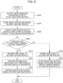
- FIG. 5 is a flowchart illustrating an example of a procedure of a process of determining whether to start induction heating, performed by the inhaler device 100 according to the present embodiment.
- the senor 112 accepts a user operation for an instruction to start induction heating (S102).
- the controller 116 determines whether the temperature of the switching element 164 is higher than or equal to the first threshold (step S104).
- step S104 If determining that the temperature of the switching element 164 is higher than or equal to the first threshold (step S104: YES), the controller 116 prohibits the start of induction heating (step S106).
- the notifier 113 provides information indicating that the start of induction heating is prohibited (step S108).
- the notifier 113 may also provide information indicating a period before the start of induction heating is permitted. The process then ends.
- step S104 determines that the temperature of the switching element 164 is lower than the first threshold (step S104: NO)
- the controller 116 permits the start of induction heating (step S110).
- step S112 the controller 116 performs induction heating (step S112). For example, the controller 116 performs electric power supply from the power supply 111 to the drive circuit 169, based on the heating profile. The process then ends.
- the controller 116 can switch the heating profile to be used between a plurality of heating profiles. In response to switching the heating profile to be used, the controller 116 controls induction heating based on the heating profile after the switching.
- the controller 116 can switch the heating profile to be used while induction heating is performed. For example, after starting induction heating based on a first heating profile, the controller 116 may start induction heating based on a second heating profile in response to a user operation. Such a configuration enables the heating profile to be switched to a heating profile corresponding to a user's preference, such as switching to the second heating profile having a higher target temperature than the first heating profile, while induction heating is performed.
- the elapsed time from the start of heating may be continuously used before and after the switching of the heating profile. For example, when heating using the first heating profile is performed until the initial temperature rise period elapses, the controller 116 may start heating using the second heating profile from the intermediate temperature drop period.
- the controller 116 may control whether to permit switching to the second heating profile after induction heating based on the first heating profile is started. For example, when a user operation for an instruction to switch the heating profile to the second heating profile is detected, the controller 116 may determine whether to permit the switching. Such a configuration can suppress the occurrence of a heat-induced issue in the switching element 164 due to switching of the heating profile.
- the controller 116 determines whether the temperature of the switching element 164 is higher than or equal to a second threshold set in the second heating profile. If the temperature of the switching element 164 is higher than or equal to the second threshold, the controller 116 prohibits switching to the second heating profile. That is, the controller 116 continues induction heating based on the first heating profile. On the other hand, if the temperature of the switching element 164 is higher than or equal to the second threshold, the controller 116 permits switching to the second heating profile. That is, the controller 116 starts induction heating based on the second heating profile.
- the second threshold is set as a temperature at which it is estimated that the temperature of the switching element 164 does not reach a temperature at which a heat-induced issue may occur, over the entire remaining period of the heating session if the temperature of the switching element 164 is lower than the second threshold at the switching.
- Such a configuration can suppress the occurrence of a heat-induced issue in the switching element 164 due to the switching of the heating profile.
- the controller 116 may set the second threshold in accordance with the elapsed time from the start of induction heating at the timing of switching the heating profile.
- An example of the timing at which the heating profile is switched is a timing at which a user operation for an instruction to switch the heating profile to the second heating profile is detected.
- the second threshold in the case of switching the heating profile at the end of the initial temperature rise period may be different from the second threshold in the case of switching the heating profile at the end of the intermediate temperature drop period. Such a configuration can appropriately adjust the second threshold in accordance with the switching timing of the heating profile.
- the notifier 113 may provide information indicating that switching of the heating profile is prohibited. In an example, the notifier 113 may provide information indicating that the switching element 164 has a high temperature. Such a configuration allows the user to know the reason why the heating profile is not switched. This thus can reduce the stress felt by the user because the inhaler device 100 does not operate in accordance with the user operation.
- Fig. 6 is a flowchart illustrating an example of a procedure of a process of determining whether to switch the heating profile during induction heating, performed by the inhaler device 100 according to the present embodiment.
- the sensor 112 accepts a user operation for an instruction to start induction heating (step S202).
- the controller 116 starts induction heating based on the first heating profile (step S204).
- the sensor 112 accepts a user operation for an instruction to switch the heating profile to the second heating profile (step S206).
- the controller 116 determines whether the temperature of the switching element 164 is higher than or equal to the second threshold (step S208).
- step S208 If determining that the temperature of the switching element 164 is higher than or equal to the second threshold (step S208: YES), the controller 116 prohibits switching to the second heating profile (step S210).
- the controller 116 provides information indicating that switching of the heating profile is prohibited (step S212).
- step S214 the controller 116 continues induction heating based on the first heating profile. The process then ends.
- step S208 determines that the temperature of the switching element 164 is lower than the second threshold (step S208: NO)
- the controller 116 permits switching to the second heating profile (step S216).
- the controller 116 starts induction heating based on the second heating profile in midstream of the second heating profile (step S218). That is, the controller 116 controls induction heating based on the second heating profile, using the elapsed time from the start of induction heating based on the first heating profile as the elapsed time from the start of induction heating. The process then ends.
- the controller 116 stops induction heating.
- the third threshold is set as a high temperature that is not to be reached when the inhaler device 100 performs a normal operation.
- the third threshold is set as a temperature at which it is estimated that a heat-induced issue may occur in the switching element 164 if the temperature of the switching element 164 exceeds a third temperature. It is considered that such a situation may occur when a temporary failure occurs in the switching element 164.
- the above configuration can suppress the occurrence of a heat-induced issue in the switching element 164 even when a temporary failure occurs.
- the notifier 113 may function as a second notifier that provides information indicating that induction heating is stopped.
- the notifier 113 may provide information indicating that the switching element 164 has a high temperature. Such a configuration allows the user to know the reason why induction heating is stopped. This thus can reduce the stress felt by the user because of interruption of the heating session.
- the controller 116 determines that the switching element 164 has failed. That is, when the number of times induction heating is stopped is greater than or equal to the fourth threshold, the controller 116 determines that the switching element 164 has failed.
- the fourth threshold is set as a value at which it can be reasonably considered that a non-temporary (that is, permanent or irreversible) failure has occurred in the switching element 164 when the number of times the temperature of the switching element 164 becomes higher than or equal to the third threshold reaches the fourth threshold. If determining that the switching element 164 has failed, the controller 116 prohibits subsequent induction heating unless the switching element 164 is repaired. Such a configuration can guarantee the safety even when a non-temporary failure occurs in the switching element 164.
- the notifier 113 may function as a third notifier that provides information indicating that the switching element 164 has failed.
- the notifier 113 provides information for prompting the user to send the inhaler device 100 for repair or replace the inhaler device 100.
- Such a configuration can continuously provide a safe puff experience to the user
- the controller 116 may adjust the first threshold. Specifically, the controller 116 may decrease the first threshold. Consequently, the start of induction heating is prohibited at a temperature lower than the temperature set before the adjustment. It is considered that if a temporary failure occurs in the switching element 164, a heat-induced issue is more likely to occur in the switching element 164 such as the switching element 164 is likely to have a high temperature, than in a case where a temporary failure has not occurred. However, the above configuration can further suppress the occurrence of a heat-induced issue in the switching element 164.
- the controller 116 may adjust the second threshold when the temperature of the switching element 164 becomes higher than or equal to the third threshold while induction heating is performed. Specifically, the controller 116 may decrease the second threshold. Consequently, switching of the heating profile is prohibited at a temperature lower than the temperature set before the adjustment.
- the above configuration can further suppress the occurrence of a heat-induced issue in the switching element 164.
- Fig. 7 is a flowchart illustrating an example of a procedure of a process of determining a failure, performed by the inhaler device 100 according to the present embodiment.
- the sensor 112 accepts a user operation for an instruction to start induction heating (step S302).
- the controller 116 starts induction heating based on the heating profile (step S304).
- the controller 116 determines whether the temperature of the switching element 164 is higher than or equal to the third threshold (step S306).
- step S306 If determining that the temperature of the switching element 164 is higher than or equal to the third threshold (step S306: YES), the controller 116 stops induction heating (step S308).
- the controller 116 determines whether the number of times the temperature of the switching element 164 becomes higher than or equal to the third threshold is greater than or equal to the fourth threshold (step S310).
- step S310 determines that the number of times the temperature of the switching element 164 becomes higher than or equal to the third threshold is greater than or equal to the fourth threshold (step S310: YES)
- the notifier 113 provides information indicating that the switching element 164 has failed (step S312). The process then ends.
- step S310 determines that the number of times the temperature of the switching element 164 becomes higher than or equal to the third threshold is less than the fourth threshold (step S310: NO)
- the notifier 113 provides information indicating that induction heating is stopped (step S314). The process then ends.
- step S306 determines that the temperature of the switching element 164 is lower than the third threshold (step S306: NO)
- the controller 116 continues induction heating (step S316). The process then ends.
- the controller 116 may prohibit/stop electric power supply from the power supply 111 to the inverter circuit 163 to prohibit or stop induction heating. With such a configuration, since DC electric power is not supplied to the inverter circuit 163, a varying magnetic field is not generated and the susceptor 161 is not heated. Thus, an increase in the temperature in response to switching performed by the switching element 164 can be suppressed.
- the controller 116 may prohibit or stop driving of all the switching elements 164 included in the inverter circuit 163 to prohibit or stop induction heating. With such a configuration, an increase in the temperature in response to switching performed by the switching elements 164 can be suppressed.
- driving of the switching elements 164 is prohibited or stopped, DC electric power is not converted into AC electric power.
- a varying magnetic field is not generated.
- the susceptor 161 is not heated.
- the determination based on the first threshold may be performed at the end of induction heating.
- the controller 116 compares the temperature of the switching element 164 with the first threshold when induction heating based on the heating profile ends.
- the notifier 113 may provide information indicating a period before the start of next induction heating is permitted, based on a difference between the temperature of the switching element 164 and the first threshold.
- the continuous puff experience means that performing puffs by repeating a heating session a plurality of times while replacing a plurality of stick substrates 150.
- the susceptor 161 is a piece of metal.
- the present invention is not limited to such an example.
- the susceptor 161 may have an elongated shape such as a rod shape, a cylindrical shape, or a plate shape.
- the susceptor 161 is desirably disposed at the center of the substrate 151 to extend in a longitudinal direction of the substrate 151.
- an aerosol can be generated in a short time from the start of heating since the susceptor 161 that produces a large amount of heat by induction heating is disposed at the center of the substrate 151.
- the susceptors 161 having a plurality of shapes may coexist in the substrate 151.
- the susceptor 161 may be disposed at any position where the susceptor 161 is in thermal proximity to the aerosol source.
- the susceptor 161 may have a blade-like shape, and may be disposed so that the susceptor 161 protrudes from the bottom 143 of the holder 140 toward the internal space 141.
- the susceptor 161 having the blade-like shape may be inserted so as to pierce the substrate 151 from the end portion of the stick substrate 150 in the insertion direction.
- the susceptor 161 may be disposed on an inner wall of the holder 140 that forms the internal space 141.
- the series of steps performed by the individual devices described in this specification may be implemented by using any of software, hardware, and a combination of software and hardware.
- Programs constituting software are, for example, stored in advance in recording media (non-transitory media) provided inside or outside the individual devices.
- Each program is, for example, at the time of being executed by a computer that controls each of the devices described in this specification, loaded into a RAM and executed by a processor such as a CPU.
- the recording media are, for example, a magnetic disk, an optical disc, a magneto-optical disk, a flash memory, and the like.
- the computer programs may be distributed, for example, via a network without using recording media.
Landscapes
- General Induction Heating (AREA)
Applications Claiming Priority (1)
| Application Number | Priority Date | Filing Date | Title |
|---|---|---|---|
| PCT/JP2021/010850 WO2022195770A1 (ja) | 2021-03-17 | 2021-03-17 | 吸引装置、プログラム及びシステム |
Publications (1)
| Publication Number | Publication Date |
|---|---|
| EP4226789A1 true EP4226789A1 (en) | 2023-08-16 |
Family
ID=83322019
Family Applications (1)
| Application Number | Title | Priority Date | Filing Date |
|---|---|---|---|
| EP21931522.3A Withdrawn EP4226789A1 (en) | 2021-03-17 | 2021-03-17 | Inhalation device, program, and system |
Country Status (3)
| Country | Link |
|---|---|
| EP (1) | EP4226789A1 (ja) |
| JP (1) | JPWO2022195770A1 (ja) |
| WO (1) | WO2022195770A1 (ja) |
Family Cites Families (3)
| Publication number | Priority date | Publication date | Assignee | Title |
|---|---|---|---|---|
| US4809677A (en) | 1987-09-14 | 1989-03-07 | The Boc Group, Inc. | Heater traverse mechanism for infant care center |
| TWI692274B (zh) * | 2014-05-21 | 2020-04-21 | 瑞士商菲利浦莫里斯製品股份有限公司 | 用於加熱氣溶膠形成基材之感應加熱裝置及操作感應加熱系統之方法 |
| TW201902372A (zh) * | 2017-05-31 | 2019-01-16 | 瑞士商菲利浦莫里斯製品股份有限公司 | 氣溶膠產生裝置之加熱構件 |
-
2021
- 2021-03-17 JP JP2023506596A patent/JPWO2022195770A1/ja not_active Withdrawn
- 2021-03-17 EP EP21931522.3A patent/EP4226789A1/en not_active Withdrawn
- 2021-03-17 WO PCT/JP2021/010850 patent/WO2022195770A1/ja unknown
Also Published As
| Publication number | Publication date |
|---|---|
| JPWO2022195770A1 (ja) | 2022-09-22 |
| WO2022195770A1 (ja) | 2022-09-22 |
Similar Documents
| Publication | Publication Date | Title |
|---|---|---|
| JP6928714B2 (ja) | 誘導ヒーターおよび移動可能な構成要素を有するエアロゾル発生装置 | |
| EP3544452B1 (en) | Inductive heating device, aerosol-generating system comprising an inductive heating device and method of operating the same | |
| WO2021012318A1 (zh) | 一种加热不燃烧烟草制品烟气持续释放的控制方法 | |
| EP4226797A1 (en) | Inhalation device, control method, and program | |
| EP4226789A1 (en) | Inhalation device, program, and system | |
| EP4226795A1 (en) | Inhalation device, control method, and program | |
| EP4226793A1 (en) | Inhalation device, control method, and program | |
| EP4226790A1 (en) | Suction device, program, and system | |
| WO2023026408A1 (ja) | 吸引装置、基材、及び制御方法 | |
| EP4226791A1 (en) | Suction device, program, and system | |
| EP4245169A1 (en) | Inhalation device, program, and system | |
| US20230371602A1 (en) | Inhalation device, base material, control method, and non-transitory computer readable medium | |
| EP4226788A1 (en) | Inhalation device, program, and system | |
| EP4316286A1 (en) | Inhalation device, control method, and program | |
| EP4316290A1 (en) | Inhalation device, control method, and program | |
| WO2022224318A1 (ja) | 制御装置、基材、システム、制御方法及びプログラム | |
| WO2023157276A1 (ja) | 誘導加熱システム、制御方法、及びプログラム | |
| EP4353106A1 (en) | Inhalation device, base material, and control method | |
| EP4226787A1 (en) | Suction device, program, and system | |
| WO2023042361A1 (ja) | エアロゾル生成システム、制御方法、及びプログラム | |
| WO2023286116A1 (ja) | 吸引装置、基材、及び制御方法 | |
| WO2023088447A1 (zh) | 气雾生成装置及控制方法 | |
| EP4356770A1 (en) | Inhalation device, substrate, and control method | |
| EP4369966A1 (en) | Aerosol-generating system with plurality of operational modes | |
| RU2792175C1 (ru) | Способ управления для непрерывного выпуска дыма из нагреваемого без горения табачного изделия |
Legal Events
| Date | Code | Title | Description |
|---|---|---|---|
| STAA | Information on the status of an ep patent application or granted ep patent |
Free format text: STATUS: THE INTERNATIONAL PUBLICATION HAS BEEN MADE |
|
| PUAI | Public reference made under article 153(3) epc to a published international application that has entered the european phase |
Free format text: ORIGINAL CODE: 0009012 |
|
| STAA | Information on the status of an ep patent application or granted ep patent |
Free format text: STATUS: REQUEST FOR EXAMINATION WAS MADE |
|
| 17P | Request for examination filed |
Effective date: 20230510 |
|
| AK | Designated contracting states |
Kind code of ref document: A1 Designated state(s): AL AT BE BG CH CY CZ DE DK EE ES FI FR GB GR HR HU IE IS IT LI LT LU LV MC MK MT NL NO PL PT RO RS SE SI SK SM TR |
|
| STAA | Information on the status of an ep patent application or granted ep patent |
Free format text: STATUS: THE APPLICATION HAS BEEN WITHDRAWN |
|
| 18W | Application withdrawn |
Effective date: 20231012 |