EP4224042B1 - Clapet anti-retour - Google Patents
Clapet anti-retour Download PDFInfo
- Publication number
- EP4224042B1 EP4224042B1 EP22155598.0A EP22155598A EP4224042B1 EP 4224042 B1 EP4224042 B1 EP 4224042B1 EP 22155598 A EP22155598 A EP 22155598A EP 4224042 B1 EP4224042 B1 EP 4224042B1
- Authority
- EP
- European Patent Office
- Prior art keywords
- piston
- backflow preventer
- spindle
- pressure cylinder
- valve according
- Prior art date
- Legal status (The legal status is an assumption and is not a legal conclusion. Google has not performed a legal analysis and makes no representation as to the accuracy of the status listed.)
- Active
Links
- 238000007789 sealing Methods 0.000 claims description 15
- 238000011144 upstream manufacturing Methods 0.000 claims 1
- XLYOFNOQVPJJNP-UHFFFAOYSA-N water Substances O XLYOFNOQVPJJNP-UHFFFAOYSA-N 0.000 description 39
- 229910001369 Brass Inorganic materials 0.000 description 7
- 239000010951 brass Substances 0.000 description 7
- 238000011161 development Methods 0.000 description 4
- 230000018109 developmental process Effects 0.000 description 4
- 230000006835 compression Effects 0.000 description 3
- 238000007906 compression Methods 0.000 description 3
- 238000006073 displacement reaction Methods 0.000 description 3
- 238000009434 installation Methods 0.000 description 2
- 238000000034 method Methods 0.000 description 2
- 239000004809 Teflon Substances 0.000 description 1
- 229920006362 Teflon® Polymers 0.000 description 1
- 238000004026 adhesive bonding Methods 0.000 description 1
- 230000007423 decrease Effects 0.000 description 1
- 238000004519 manufacturing process Methods 0.000 description 1
- 239000000463 material Substances 0.000 description 1
- 230000009972 noncorrosive effect Effects 0.000 description 1
- 229910001220 stainless steel Inorganic materials 0.000 description 1
- 239000010935 stainless steel Substances 0.000 description 1
- 230000007704 transition Effects 0.000 description 1
Images


Classifications
-
- F—MECHANICAL ENGINEERING; LIGHTING; HEATING; WEAPONS; BLASTING
- F16—ENGINEERING ELEMENTS AND UNITS; GENERAL MEASURES FOR PRODUCING AND MAINTAINING EFFECTIVE FUNCTIONING OF MACHINES OR INSTALLATIONS; THERMAL INSULATION IN GENERAL
- F16K—VALVES; TAPS; COCKS; ACTUATING-FLOATS; DEVICES FOR VENTING OR AERATING
- F16K1/00—Lift valves or globe valves, i.e. cut-off apparatus with closure members having at least a component of their opening and closing motion perpendicular to the closing faces
- F16K1/02—Lift valves or globe valves, i.e. cut-off apparatus with closure members having at least a component of their opening and closing motion perpendicular to the closing faces with screw-spindle
-
- F—MECHANICAL ENGINEERING; LIGHTING; HEATING; WEAPONS; BLASTING
- F16—ENGINEERING ELEMENTS AND UNITS; GENERAL MEASURES FOR PRODUCING AND MAINTAINING EFFECTIVE FUNCTIONING OF MACHINES OR INSTALLATIONS; THERMAL INSULATION IN GENERAL
- F16K—VALVES; TAPS; COCKS; ACTUATING-FLOATS; DEVICES FOR VENTING OR AERATING
- F16K1/00—Lift valves or globe valves, i.e. cut-off apparatus with closure members having at least a component of their opening and closing motion perpendicular to the closing faces
- F16K1/32—Details
-
- F—MECHANICAL ENGINEERING; LIGHTING; HEATING; WEAPONS; BLASTING
- F16—ENGINEERING ELEMENTS AND UNITS; GENERAL MEASURES FOR PRODUCING AND MAINTAINING EFFECTIVE FUNCTIONING OF MACHINES OR INSTALLATIONS; THERMAL INSULATION IN GENERAL
- F16K—VALVES; TAPS; COCKS; ACTUATING-FLOATS; DEVICES FOR VENTING OR AERATING
- F16K39/00—Devices for relieving the pressure on the sealing faces
- F16K39/02—Devices for relieving the pressure on the sealing faces for lift valves
Definitions
- the invention relates to a backflow preventer valve, with a head piece in which a pressure cylinder is arranged, which is connected to a spindle, via the rotation of which the pressure cylinder can be displaced in the head piece and which receives a check piston which is displaceably arranged in a first piston chamber of the pressure cylinder and which is provided with a sealing arrangement at the end.
- Such backflow preventer valves such as those in EP 2 325 533 B1 are used in shut-off valves.
- a sealing element is arranged on a piston and can be inserted into the line path within the fitting, whereby the flow is blocked.
- the piston is arranged at an angle to the line and is connected to a handwheel through which the piston can be moved.
- the piston is regularly preloaded towards the sealing surface via a compression spring.
- a pressure piece is arranged which can be moved around the piston onto the sealing element of the piston.
- Valve top parts of the aforementioned type have proven themselves in practice.
- the problem when shutting off the above valve is that the water displaced by the pressure piece during the process cannot escape, which means that the Pressure in the line piece increases significantly until it is no longer possible to move the pressure piece by hand.
- the significantly increasing pressure can also lead to damage to the sealing element or even the water meter.
- a backflow preventer valve in which a pressure compensation channel is guided in the sealing arrangement, in which a pressure relief valve assembly is arranged.
- This allows displaced water to escape through the pressure equalization channel if a limit pressure in the line is exceeded.
- a limit pressure in the line With this non-return valve, an excessive increase in pressure in the line is effectively prevented when the pressure piece is moved to shut off the line.
- the implementation of the pressure relief valve assembly proves to be complex. In particular, there is only a small installation space for the required pressure-limiting spring of this sealing arrangement, which means that high demands are placed on the spring to be used, since the pressure relief valve group must withstand an opening pressure of up to 16 bar.
- the invention is based on the object of creating a non-return valve of the above type, in which an excessive increase in pressure in the line is prevented when the pressure piece is moved to shut off the line and which does not require a pressure relief valve assembly in the sealing arrangement. According to the invention, this object is achieved by a backflow preventer valve with the features of the characterizing part of patent claim 1.
- the invention creates a backflow preventer valve in which an excessive increase in pressure in the line is prevented when the pressure piece is moved to shut off the line and whose sealing arrangement does not require a pressure relief valve assembly. Because the pressure cylinder includes a pressure compensation pump that is operated via the spindle, a rotation of the spindle to move the pressure cylinder simultaneously causes the pressure compensation pump to be driven, as a result of which the water displaced by the pressure cylinder during the process is sucked out. As a result, the pressure in the line piece no longer increases, and movement of the pressure piece by hand remains possible without any restrictions.
- the pressure compensation pump is formed by a second piston chamber of the pressure cylinder, which has a through-channel is connected to the first piston chamber and in which a pump piston is slidably arranged, which is connected via a threaded engagement to the spindle, via the rotation of which it is displaceable.
- the check piston is guided in the first piston chamber via a sliding ring which is provided with a pressure compensation gap. This enables the check piston to be guided without impairing the connection between the second piston chamber and the line piece into which the non-return valve is inserted.
- the pump piston has a guide rod which projects through the through-channel. This ensures reliable guidance of the pump piston, which counteracts unwanted tilting.
- the check piston has an axial blind bore into which the guide rod engages in a position of the check piston retracted into the first piston chamber, a radial pressure compensation bore being introduced into the check piston, which opens into the axial blind bore.
- a spring is arranged in the axial blind bore of the check piston and is biased against the pressure cylinder. This prevents water from flowing back into the line into which the backflow preventer valve is inserted when the line pressure decreases.
- the spring which is preferably designed as a compression coil spring, has sufficient installation space between the inner wall of the blind bore of the check piston and the guide rod.
- the pump piston has a drive rod which is in threaded engagement with the spindle.
- the drive rod preferably has an external thread that engages in a threaded hole made in the spindle. This causes an axial movement of the drive rod and thus of the pump piston when the spindle rotates.
- the spindle is connected in a rotationally fixed manner to a threaded bell which has a first internal thread which engages with an external thread arranged on the outside of the head piece. This causes the pressure cylinder receiving the check piston to be displaced by rotating the spindle.
- a section with a reduced internal diameter is arranged in the thread bell axially in front of the first internal thread and has a second internal thread which engages with an external thread arranged on the outside of the printing cylinder.
- the first internal thread is advantageously directed in the opposite direction to the internal thread engaging in the external thread of the printing cylinder.
- the first internal thread is a right-hand thread and the second internal thread is a left-hand thread.
- the threaded bell is formed from a cup-shaped support piece which has a hollow cylindrical extension which has the second internal thread and which is provided with an external thread, onto which a threaded sleeve which extends in length is screwed on and non-removably fixed, in particular glued which has the first internal thread.
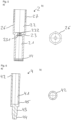
- the backflow preventer valve chosen as an exemplary embodiment essentially consists of a head piece 1, which is penetrated by a pressure cylinder 2, which receives a pump piston 3 and in which a check piston 4 is arranged, to which a conical disk 6 is attached, the pressure cylinder 2 and the pump piston 3 are connected via a spindle 5 to a handwheel 57, via which they can be moved axially in the head piece 1 in mutually opposite directions.
- the head piece 1 is a largely hollow cylindrical brass turned part. At its lower, fitting-side end, a first external thread 11 is attached to the head piece 1, which is delimited by a circumferential collar 12.
- the collar 12 is adjoined by an external hexagon 13, which merges into a section with a tapered external diameter and a second one at the end External thread 14 for receiving the threaded sleeve 77 of the threaded bell 7 is introduced.
- the external thread 14 is designed as a right-hand trapezoidal thread.
- an internal hexagonal collar 15 is inserted into the head piece 1 at the level of the second external thread 14 to guide and prevent the printing cylinder 2 from rotating.
- two grooves 16 for receiving O-rings 17 are introduced into the head piece 1 parallel to one another.
- An O-ring 18 is arranged on the outside of the head piece 1 below the collar 12 for sealing against a fitting 9.
- the pressure cylinder 2 is designed as a substantially hollow cylindrical brass turned part and has a cylindrical first piston chamber 21 and a cylindrical second piston chamber 22 with an enlarged diameter compared to this, which are connected to one another via a through channel 23.
- the through channel 23 is provided at its end facing the first piston chamber 21 with a diameter expansion 231, into which axial notches 232, which are made all the way around its inner surface and run over the entire length, open, whereby an anti-rotation guide in the manner of a hexagon socket is achieved.
- the first piston chamber 21 of the pressure cylinder 2 has, at its end opposite the through-channel 23, a shoulder 24 with an enlarged diameter for receiving a sliding ring 25, via which the check piston 4 is slidably guided in the first piston chamber 21.
- a hexagon-shaped section 26 On the outside of the pressure cylinder 2 in the area of the second piston chamber 21 there is a hexagon-shaped section 26, which is adjoined by an external thread 27, which in the exemplary embodiment is designed as a trapezoidal left-hand thread.
- the outer contour of the hexagon-shaped section 26 essentially corresponds to the inner contour of the hexagon socket collar 15 of the head piece 1, through which it is guided.
- the pump piston 3 has a cylindrical piston section 31, which is provided on the outside with two spaced-apart grooves 32, in each of which an O-ring 33 is inserted for sealing against the second piston chamber 22 of the pressure cylinder 2.
- the piston section 31 goes centrally into a drive rod 34 about, which has an enlarged diameter section 35 at the end, which is provided with an external thread 36, which is designed as a right-hand trapezoidal thread and via which the drive rod 34 is connected to the spindle 5.
- An annular groove 37 is introduced into the piston section 31 surrounding the drive rod 34.
- the piston section 31 merges into a central guide rod 38 with a hexagonal cross-section, with which it is guided against rotation in the through channel 23 of the printing cylinder 2, which it penetrates.
- the spindle 5 is designed as a substantially cylindrical brass turned part.
- the spindle 5 is divided into a cylindrical section 51 and a square-shaped section 52, between which a circumferential collar 53 is arranged, on which a hexagonal shoulder 531 is arranged.
- a first axial threaded hole 54 is introduced centrally into the spindle 5, which in the exemplary embodiment has a trapezoidal right-hand thread into which the drive rod 34 of the pump piston 3 engages with its external thread 36.
- a second axial threaded bore 55 which has a metric internal thread, is centrally introduced into the square-shaped section 52.
- the threaded hole 55 is used to receive a screw 56 for fastening the handwheel 57 which is attached to the square section 52.
- a threaded bell 7 is applied to the spindle 5 between the pressure cylinder 2 and the handwheel 57.
- the threaded bell 7 is formed from a support piece 71 and a threaded sleeve 77.
- the support piece 71 is designed as a substantially cup-shaped brass turned part and has a circular disk 72 on which a hollow cylindrical extension 74 is arranged, which it projects all around.
- a hexagon-shaped recess 73 is made in the disk 72, with which the carrier piece 71 of the threaded bell 7 rests on the hexagonal section 531 of the collar 53 of the spindle 5.
- the threaded bell 7 is connected to the spindle 5 in a form-fitting manner.
- the extension 74 is provided on the inside with a first internal thread 75, which is designed as a trapezoidal left-hand thread for engagement with the external thread 27 of the printing cylinder 2.
- the approach 74 has a right-hand trapezoidal thread External thread 76.
- the threaded sleeve 77 is designed as a hollow cylindrical brass turned part and is provided with a second internal thread 78, which is designed as a right-hand trapezoidal thread.
- the threaded sleeve 77 is screwed with its second internal thread 78 onto the external thread 76 of the extension 74 of the support piece 71 and glued to it, whereby it axially projects beyond the extension 74 of the support piece 71 with approximately half its length.
- a thermal and/or mechanical non-detachable connection of the carrier piece 71 and the threaded sleeve 72 is also possible.
- the thread bell 7 formed in this way has, axially and radially offset from one another, a first internal thread 75 designed as a left-hand trapezoidal thread for engagement with the external thread 27 of the printing cylinder 2 and a second internal thread 78 designed as a right-hand trapezoidal thread for engagement with the second external thread 14 of the head piece 1 .
- the check piston 4 is essentially designed as a cylindrical turned brass part. At its end facing the through channel 23 of the pressure cylinder 2, a blind hole 41 for receiving a spring 8 is introduced axially into the check piston 4. At its end facing the spindle 5, an external polygon 42 is arranged on the outside of the check piston 4. A gap for the passage of water is thus formed between the check piston 4 and the cylindrical first piston chamber 21. At its end opposite the outer polygon 42, the check piston 4 has a pin 43 for receiving the conical disk 6, which merges into a threaded head 44 at the end.
- the outer lateral surface of the check piston 4 is provided with a Teflon layer in the entire area that is axially displaceable within the first piston space 21 of the pressure cylinder 2, that is, from the outer polygon 42 to the pin 43.
- the check piston 4 can also be made of a non-corrosive material such as stainless steel.
- Blind holes 41 are introduced into the check piston 4 pressure compensation holes 45, which serve for the entry or exit of water when the check piston 4 moves within the first piston chamber 21.
- the pressure compensation bores 45 open into the space formed between the check piston 4 and the cylindrical first piston chamber 21.
- the conical disk 6 is pushed onto the pin 43 of the check piston 4.
- the conical disk 6 is designed as a turned brass part.
- a conical shoulder 61 is arranged on the conical disk 6.
- the conical disk 6 On its side opposite the conical shoulder 61, the conical disk 6 has a section 62 with a reduced diameter.
- the conical disk 6 is centrally provided with a stepped bore 63, which is designed to have an enlarged diameter in the area of the transition to the reduced-diameter section 62, whereby a shoulder 64 for receiving an O-ring 65 is formed.
- a sealing disk 66 is placed on the conical shoulder 61 of the conical disk 6 and the conical disk 6 and sealing disk 66 are fastened to the check piston 4 by means of a collar nut 46 which is screwed onto the threaded head 44 of the pin 43.
- the conical disk 6 is sealed against the pin 43 of the check piston 4 via the O-ring 65.
- the spindle 5 is screwed with its first threaded bore 54 onto the external thread 36 of the drive rod 34 of the pump piston 3, which is inserted into the second piston chamber 22 of the pressure cylinder, its piston section 31 being opposite the second piston chamber 22 via the O-rings 33 is sealed and its guide rod 38 protrudes through the passage channel 23 of the printing cylinder 2 into the first piston chamber 21.
- the threaded bell 7 is placed on the collar 53 of the spindle 5 and rests on the collar 53, the hexagonal shoulder 531 of the collar engaging in the hexagonal recess 73 of the disk 72, whereby the threaded bell 7 and the spindle 5 are positively connected.
- the handwheel 57 is placed on the square section 52 of the spindle 5 and connected to it via the screw 56, which is screwed into the second threaded hole 55 of the spindle 5.
- the threaded bell 7, which is axially fixed on the spindle 5 via the handwheel 57, is with its first internal thread 75 in engagement with the external thread 27 of the printing cylinder 2 and with its second internal thread 78 in engagement with the second external thread 14 of the head piece 1.
- the check piston 4 is inserted with its outer polygon 42 into the cylindrical first piston chamber 21 of the printing cylinder 2, a spring 8 being inserted into the check piston 4, which is designed as a compression coil spring and which has its other end at the bottom of the first piston chamber 21 of the printing cylinder 2 the diameter expansion 231 of the through channel 23 rests surrounding it, against which it is biased.
- the guide rod 38 projects into the blind bore 41 of the check piston 4 and the spring 8 arranged therein.
- the check piston 4 is guided in the pressure cylinder 2 over the sliding ring 25, which has a pressure compensation gap 251 for the passage of water for pressure compensation.
- the pressure cylinder 2 is sealed via the two O-rings 17 relative to the head piece 1, which is screwed with its first external thread 11 into a fitting 9 - only shown schematically in the figures.
- the head piece 1 is sealed from the fitting 9 via the O-ring 18.
- the fitting 9 includes a water inlet 91 and a water outlet 93.
- the water inlet 91 has a stop 92 against which the sealing disk 66 attached to the check piston 4 rests.
- the check piston 4 is biased against the stop 92 via the spring 8. No water flows from the water inlet 91 to the water outlet 93.
- the pressure p in the water outlet 93 increases.
- the pressure cylinder 2 moves by rotating the spindle 5 via the handwheel 57 in the direction of the conical disk 6 to block the water inlet 91
- the threaded engagement between the spindle 5 and the drive rod 34 which runs in the opposite direction to the threaded engagement between the threaded bell 7 and the pressure cylinder 2
- the piston section 31 of the pump piston 3 moves upwards towards the spindle 5, whereby the water displaced by the pressure cylinder 2 is sucked through the pressure compensation gap 251 of the sliding ring 25 via the space formed between the check piston 4 and the first piston chamber 21 through the through-channel 23 into the second piston chamber 22.
- the volume available for this purpose in the second piston chamber 22 is maximized by the annular groove 37 arranged in the piston section 31.
- the diameter expansion 231 of the through-channel 23 ensures that water flow around the guide rod 38 guided through the through-channel 23 is guaranteed at all times.
- the pressure p present in the water drain 93 remains approximately constant.
- the negative pressure in the blind bore 41 caused by the movement of the check piston 4 out of the first piston chamber 21 is compensated for by the pressure compensation bore 45 arranged therein.
- the pressure p present in the water outlet 93 remains approximately constant.
- the excess pressure in the blind bore 41 caused by the movement of the check piston 4 into the first piston chamber 21 is in turn compensated for by the pressure compensation bore 45 arranged therein.
Claims (10)
- Vanne à clapet antiretour, comprenant une pièce têtière (1) dans laquelle est disposé un cylindre de compression (2), cylindre qui est relié avec une broche (5) via la rotation de laquelle le cylindre de compression (2) est déplaçable dans la pièce têtière (1) et qui reçoit un piston antiretour (4) disposé déplaçable dans un premier volume (21) à piston du cylindre de compression (2), et qui à son extrémité est muni d'un dispositif d'étanchéité, caractérisée en ce que le cylindre de compression (2) comprend une pompe d'équilibrage de pression actionnée via la broche (5).
- Vanne à clapet antiretour selon la revendication 1, caractérisée en ce que la pompe d'équilibrage de pression est formée par un deuxième volume (22) à piston du cylindre de compression (22), lequel deuxième volume est relié avec le premier volume (21) à piston via un conduit traversant (23) et dans lequel un piston (3) de pompe est disposé déplaçable, piston qui est relié avec la broche (5) par filetage d'engrènement interposé, broche via la rotation de laquelle il peut être déplacé.
- Vanne à clapet antiretour selon la revendication 1 ou 2, caractérisée en ce que le piston antiretour (4) est guidé dans le premier volume (21) à piston via une bague coulissante (25) qui présente une fente d'équilibrage de pression (251).
- Vanne à clapet antiretour selon la revendication 2 ou 3, caractérisée en ce que le piston (3) de pompe présente une barre de guidage (38) qui fait saillie à travers le canal traversant (23).
- Vanne à clapet antiretour selon la revendication 4, caractérisée en ce que le piston antiretour (4) présente un alésage borgne (41) axial dans lequel la barre de guidage (38) engrène lorsque le piston antiretour (4) se trouve en position rentrée dans le premier volume (21) de piston, sachant que dans le piston antiretour (4) a été ménagé de préférence un alésage radial d'équilibrage de pression (45) qui aboutit dans l'alésage borgne (41) axial.
- Vanne à clapet antiretour selon la revendication 5, caractérisée en ce que dans l'alésage borgne (41) axial du piston antiretour (4) a été disposé un ressort (8) précontraint contre le cylindre de compression (2).
- Vanne à clapet antiretour selon l'une quelconque des revendications 2 à 6, caractérisée en ce que le piston (3) de pompe présente une barre d'entraînement (34) qui engrène avec la broche (5) par filetage interposé, sachant que la barre d'entraînement (34) présente de préférence un filetage externe (36) qui engrène dans un alésage fileté (54) ménagé dans la broche (5).
- Vanne à clapet antiretour selon l'une quelconque des revendications précédentes, caractérisée en ce que la broche (5) est reliée sans pouvoir tourner avec une cloche filetée (7), cloche qui présente un premier filetage intérieur (75), lequel engrène avec un filetage extérieur (14) disposé à l'extérieur contre la pièce têtière (1).
- Vanne à clapet antiretour selon la revendication 8, caractérisée en ce que dans la cloche filetée (7) est disposé axialement, devant le premier filetage intérieur (75), un segment d'un diamètre intérieur réduit, lequel présente un second filetage intérieur (78) qui engrène avec un filetage extérieur (27) disposé à l'extérieur contre le cylindre de compression (2), sachant que de préférence le premier filetage intérieur (75) est un filetage avec pas à droite, et le deuxième filetage intérieur (78) un filetage avec pas à gauche.
- Vanne à clapet antiretour selon la revendication 9, caractérisée en ce que la cloche filetée (7) est formée par une pièce support (71) en forme de pot, qui présente un embout (74) cylindrique creux, lequel présente le deuxième filetage intérieur (78) et qui est muni d'un filetage extérieur (76) sur lequel est vissée et collée une douille filetée (77) le dépassant en longueur, douille qui présente le premier filetage intérieur (75).
Priority Applications (1)
| Application Number | Priority Date | Filing Date | Title |
|---|---|---|---|
| EP22155598.0A EP4224042B1 (fr) | 2022-02-08 | 2022-02-08 | Clapet anti-retour |
Applications Claiming Priority (1)
| Application Number | Priority Date | Filing Date | Title |
|---|---|---|---|
| EP22155598.0A EP4224042B1 (fr) | 2022-02-08 | 2022-02-08 | Clapet anti-retour |
Publications (2)
| Publication Number | Publication Date |
|---|---|
| EP4224042A1 EP4224042A1 (fr) | 2023-08-09 |
| EP4224042B1 true EP4224042B1 (fr) | 2024-03-13 |
Family
ID=80448576
Family Applications (1)
| Application Number | Title | Priority Date | Filing Date |
|---|---|---|---|
| EP22155598.0A Active EP4224042B1 (fr) | 2022-02-08 | 2022-02-08 | Clapet anti-retour |
Country Status (1)
| Country | Link |
|---|---|
| EP (1) | EP4224042B1 (fr) |
Family Cites Families (3)
| Publication number | Priority date | Publication date | Assignee | Title |
|---|---|---|---|---|
| US4164959A (en) * | 1977-04-15 | 1979-08-21 | The Salk Institute For Biological Studies | Metering valve |
| DE102009054010B4 (de) | 2009-11-19 | 2012-02-23 | Flühs Drehtechnik GmbH | Ventiloberteil |
| DE202021101378U1 (de) | 2021-03-18 | 2021-04-07 | Flühs Drehtechnik GmbH | Rückflussverhindererventil |
-
2022
- 2022-02-08 EP EP22155598.0A patent/EP4224042B1/fr active Active
Also Published As
| Publication number | Publication date |
|---|---|
| EP4224042A1 (fr) | 2023-08-09 |
Similar Documents
| Publication | Publication Date | Title |
|---|---|---|
| EP1725796B1 (fr) | Soupape de retenue | |
| DE2435911A1 (de) | Druckabhaengiges ventil | |
| EP4060210B1 (fr) | Clapet anti-retour | |
| DE3627865A1 (de) | Rueckschlagventil | |
| EP0061415A1 (fr) | Soupape pour systèmes hydrauliques | |
| DE19602796B4 (de) | Steuerventil für kleinen Durchfluß | |
| DE3831554C2 (de) | Drosselrückschlagventil | |
| EP3366959B1 (fr) | Partie supérieure de soupape | |
| DE4025488C2 (de) | Rückschlagventil | |
| DE202022100701U1 (de) | Rückflussverhindererventil | |
| EP4224042B1 (fr) | Clapet anti-retour | |
| DE10014191B4 (de) | Steuerventil | |
| EP1001196B1 (fr) | Soupape de limitation de pression, en particulier pour des véhicules | |
| DE10356598B3 (de) | Verriegelungszylinder | |
| EP1428962A1 (fr) | Ensemble piston-cylindre | |
| EP0093783B1 (fr) | Soupape à passage directe | |
| EP4286723A1 (fr) | Soupape d'arrêt | |
| DE4417293A1 (de) | Proportional-Druckregelventil | |
| DE202023101162U1 (de) | Bedieneinrichtung für ein Ventiloberteil für Sanitärarmaturen | |
| CH703392B1 (de) | Ventil zur Druckbegrenzung sowie Vorrichtung mit einem solchen. | |
| DE202022103021U1 (de) | Absperrventil | |
| DE202023101160U1 (de) | Ventiloberteil für Sanitärarmaturen | |
| DE202023101163U1 (de) | Ventiloberteil für Sanitärarmaturen | |
| DE3620242A1 (de) | Vorsteuerventil, insbesondere 3/2-wegeventil | |
| AT216851B (de) | Überdruckventil, insbesondere für hydraulische Arbeitskreise |
Legal Events
| Date | Code | Title | Description |
|---|---|---|---|
| PUAI | Public reference made under article 153(3) epc to a published international application that has entered the european phase |
Free format text: ORIGINAL CODE: 0009012 |
|
| STAA | Information on the status of an ep patent application or granted ep patent |
Free format text: STATUS: REQUEST FOR EXAMINATION WAS MADE |
|
| 17P | Request for examination filed |
Effective date: 20221024 |
|
| AK | Designated contracting states |
Kind code of ref document: A1 Designated state(s): AL AT BE BG CH CY CZ DE DK EE ES FI FR GB GR HR HU IE IS IT LI LT LU LV MC MK MT NL NO PL PT RO RS SE SI SK SM TR |
|
| GRAP | Despatch of communication of intention to grant a patent |
Free format text: ORIGINAL CODE: EPIDOSNIGR1 |
|
| STAA | Information on the status of an ep patent application or granted ep patent |
Free format text: STATUS: GRANT OF PATENT IS INTENDED |
|
| INTG | Intention to grant announced |
Effective date: 20230925 |
|
| GRAS | Grant fee paid |
Free format text: ORIGINAL CODE: EPIDOSNIGR3 |
|
| GRAA | (expected) grant |
Free format text: ORIGINAL CODE: 0009210 |
|
| STAA | Information on the status of an ep patent application or granted ep patent |
Free format text: STATUS: THE PATENT HAS BEEN GRANTED |
|
| AK | Designated contracting states |
Kind code of ref document: B1 Designated state(s): AL AT BE BG CH CY CZ DE DK EE ES FI FR GB GR HR HU IE IS IT LI LT LU LV MC MK MT NL NO PL PT RO RS SE SI SK SM TR |
|
| REG | Reference to a national code |
Ref country code: GB Ref legal event code: FG4D Free format text: NOT ENGLISH |
|
| REG | Reference to a national code |
Ref country code: CH Ref legal event code: EP |
|
| REG | Reference to a national code |
Ref country code: DE Ref legal event code: R096 Ref document number: 502022000590 Country of ref document: DE |