EP4224042B1 - Backflow preventer valve - Google Patents
Backflow preventer valve Download PDFInfo
- Publication number
- EP4224042B1 EP4224042B1 EP22155598.0A EP22155598A EP4224042B1 EP 4224042 B1 EP4224042 B1 EP 4224042B1 EP 22155598 A EP22155598 A EP 22155598A EP 4224042 B1 EP4224042 B1 EP 4224042B1
- Authority
- EP
- European Patent Office
- Prior art keywords
- piston
- backflow preventer
- spindle
- pressure cylinder
- valve according
- Prior art date
- Legal status (The legal status is an assumption and is not a legal conclusion. Google has not performed a legal analysis and makes no representation as to the accuracy of the status listed.)
- Active
Links
- 238000007789 sealing Methods 0.000 claims description 15
- 238000011144 upstream manufacturing Methods 0.000 claims 1
- XLYOFNOQVPJJNP-UHFFFAOYSA-N water Substances O XLYOFNOQVPJJNP-UHFFFAOYSA-N 0.000 description 39
- 229910001369 Brass Inorganic materials 0.000 description 7
- 239000010951 brass Substances 0.000 description 7
- 238000011161 development Methods 0.000 description 4
- 230000018109 developmental process Effects 0.000 description 4
- 230000006835 compression Effects 0.000 description 3
- 238000007906 compression Methods 0.000 description 3
- 238000006073 displacement reaction Methods 0.000 description 3
- 238000009434 installation Methods 0.000 description 2
- 238000000034 method Methods 0.000 description 2
- 239000004809 Teflon Substances 0.000 description 1
- 229920006362 Teflon® Polymers 0.000 description 1
- 238000004026 adhesive bonding Methods 0.000 description 1
- 230000007423 decrease Effects 0.000 description 1
- 238000004519 manufacturing process Methods 0.000 description 1
- 239000000463 material Substances 0.000 description 1
- 230000009972 noncorrosive effect Effects 0.000 description 1
- 229910001220 stainless steel Inorganic materials 0.000 description 1
- 239000010935 stainless steel Substances 0.000 description 1
- 230000007704 transition Effects 0.000 description 1
Images


Classifications
-
- F—MECHANICAL ENGINEERING; LIGHTING; HEATING; WEAPONS; BLASTING
- F16—ENGINEERING ELEMENTS AND UNITS; GENERAL MEASURES FOR PRODUCING AND MAINTAINING EFFECTIVE FUNCTIONING OF MACHINES OR INSTALLATIONS; THERMAL INSULATION IN GENERAL
- F16K—VALVES; TAPS; COCKS; ACTUATING-FLOATS; DEVICES FOR VENTING OR AERATING
- F16K1/00—Lift valves or globe valves, i.e. cut-off apparatus with closure members having at least a component of their opening and closing motion perpendicular to the closing faces
- F16K1/02—Lift valves or globe valves, i.e. cut-off apparatus with closure members having at least a component of their opening and closing motion perpendicular to the closing faces with screw-spindle
-
- F—MECHANICAL ENGINEERING; LIGHTING; HEATING; WEAPONS; BLASTING
- F16—ENGINEERING ELEMENTS AND UNITS; GENERAL MEASURES FOR PRODUCING AND MAINTAINING EFFECTIVE FUNCTIONING OF MACHINES OR INSTALLATIONS; THERMAL INSULATION IN GENERAL
- F16K—VALVES; TAPS; COCKS; ACTUATING-FLOATS; DEVICES FOR VENTING OR AERATING
- F16K1/00—Lift valves or globe valves, i.e. cut-off apparatus with closure members having at least a component of their opening and closing motion perpendicular to the closing faces
- F16K1/32—Details
-
- F—MECHANICAL ENGINEERING; LIGHTING; HEATING; WEAPONS; BLASTING
- F16—ENGINEERING ELEMENTS AND UNITS; GENERAL MEASURES FOR PRODUCING AND MAINTAINING EFFECTIVE FUNCTIONING OF MACHINES OR INSTALLATIONS; THERMAL INSULATION IN GENERAL
- F16K—VALVES; TAPS; COCKS; ACTUATING-FLOATS; DEVICES FOR VENTING OR AERATING
- F16K39/00—Devices for relieving the pressure on the sealing faces
- F16K39/02—Devices for relieving the pressure on the sealing faces for lift valves
Definitions
- the invention relates to a backflow preventer valve, with a head piece in which a pressure cylinder is arranged, which is connected to a spindle, via the rotation of which the pressure cylinder can be displaced in the head piece and which receives a check piston which is displaceably arranged in a first piston chamber of the pressure cylinder and which is provided with a sealing arrangement at the end.
- Such backflow preventer valves such as those in EP 2 325 533 B1 are used in shut-off valves.
- a sealing element is arranged on a piston and can be inserted into the line path within the fitting, whereby the flow is blocked.
- the piston is arranged at an angle to the line and is connected to a handwheel through which the piston can be moved.
- the piston is regularly preloaded towards the sealing surface via a compression spring.
- a pressure piece is arranged which can be moved around the piston onto the sealing element of the piston.
- Valve top parts of the aforementioned type have proven themselves in practice.
- the problem when shutting off the above valve is that the water displaced by the pressure piece during the process cannot escape, which means that the Pressure in the line piece increases significantly until it is no longer possible to move the pressure piece by hand.
- the significantly increasing pressure can also lead to damage to the sealing element or even the water meter.
- a backflow preventer valve in which a pressure compensation channel is guided in the sealing arrangement, in which a pressure relief valve assembly is arranged.
- This allows displaced water to escape through the pressure equalization channel if a limit pressure in the line is exceeded.
- a limit pressure in the line With this non-return valve, an excessive increase in pressure in the line is effectively prevented when the pressure piece is moved to shut off the line.
- the implementation of the pressure relief valve assembly proves to be complex. In particular, there is only a small installation space for the required pressure-limiting spring of this sealing arrangement, which means that high demands are placed on the spring to be used, since the pressure relief valve group must withstand an opening pressure of up to 16 bar.
- the invention is based on the object of creating a non-return valve of the above type, in which an excessive increase in pressure in the line is prevented when the pressure piece is moved to shut off the line and which does not require a pressure relief valve assembly in the sealing arrangement. According to the invention, this object is achieved by a backflow preventer valve with the features of the characterizing part of patent claim 1.
- the invention creates a backflow preventer valve in which an excessive increase in pressure in the line is prevented when the pressure piece is moved to shut off the line and whose sealing arrangement does not require a pressure relief valve assembly. Because the pressure cylinder includes a pressure compensation pump that is operated via the spindle, a rotation of the spindle to move the pressure cylinder simultaneously causes the pressure compensation pump to be driven, as a result of which the water displaced by the pressure cylinder during the process is sucked out. As a result, the pressure in the line piece no longer increases, and movement of the pressure piece by hand remains possible without any restrictions.
- the pressure compensation pump is formed by a second piston chamber of the pressure cylinder, which has a through-channel is connected to the first piston chamber and in which a pump piston is slidably arranged, which is connected via a threaded engagement to the spindle, via the rotation of which it is displaceable.
- the check piston is guided in the first piston chamber via a sliding ring which is provided with a pressure compensation gap. This enables the check piston to be guided without impairing the connection between the second piston chamber and the line piece into which the non-return valve is inserted.
- the pump piston has a guide rod which projects through the through-channel. This ensures reliable guidance of the pump piston, which counteracts unwanted tilting.
- the check piston has an axial blind bore into which the guide rod engages in a position of the check piston retracted into the first piston chamber, a radial pressure compensation bore being introduced into the check piston, which opens into the axial blind bore.
- a spring is arranged in the axial blind bore of the check piston and is biased against the pressure cylinder. This prevents water from flowing back into the line into which the backflow preventer valve is inserted when the line pressure decreases.
- the spring which is preferably designed as a compression coil spring, has sufficient installation space between the inner wall of the blind bore of the check piston and the guide rod.
- the pump piston has a drive rod which is in threaded engagement with the spindle.
- the drive rod preferably has an external thread that engages in a threaded hole made in the spindle. This causes an axial movement of the drive rod and thus of the pump piston when the spindle rotates.
- the spindle is connected in a rotationally fixed manner to a threaded bell which has a first internal thread which engages with an external thread arranged on the outside of the head piece. This causes the pressure cylinder receiving the check piston to be displaced by rotating the spindle.
- a section with a reduced internal diameter is arranged in the thread bell axially in front of the first internal thread and has a second internal thread which engages with an external thread arranged on the outside of the printing cylinder.
- the first internal thread is advantageously directed in the opposite direction to the internal thread engaging in the external thread of the printing cylinder.
- the first internal thread is a right-hand thread and the second internal thread is a left-hand thread.
- the threaded bell is formed from a cup-shaped support piece which has a hollow cylindrical extension which has the second internal thread and which is provided with an external thread, onto which a threaded sleeve which extends in length is screwed on and non-removably fixed, in particular glued which has the first internal thread.
- the backflow preventer valve chosen as an exemplary embodiment essentially consists of a head piece 1, which is penetrated by a pressure cylinder 2, which receives a pump piston 3 and in which a check piston 4 is arranged, to which a conical disk 6 is attached, the pressure cylinder 2 and the pump piston 3 are connected via a spindle 5 to a handwheel 57, via which they can be moved axially in the head piece 1 in mutually opposite directions.
- the head piece 1 is a largely hollow cylindrical brass turned part. At its lower, fitting-side end, a first external thread 11 is attached to the head piece 1, which is delimited by a circumferential collar 12.
- the collar 12 is adjoined by an external hexagon 13, which merges into a section with a tapered external diameter and a second one at the end External thread 14 for receiving the threaded sleeve 77 of the threaded bell 7 is introduced.
- the external thread 14 is designed as a right-hand trapezoidal thread.
- an internal hexagonal collar 15 is inserted into the head piece 1 at the level of the second external thread 14 to guide and prevent the printing cylinder 2 from rotating.
- two grooves 16 for receiving O-rings 17 are introduced into the head piece 1 parallel to one another.
- An O-ring 18 is arranged on the outside of the head piece 1 below the collar 12 for sealing against a fitting 9.
- the pressure cylinder 2 is designed as a substantially hollow cylindrical brass turned part and has a cylindrical first piston chamber 21 and a cylindrical second piston chamber 22 with an enlarged diameter compared to this, which are connected to one another via a through channel 23.
- the through channel 23 is provided at its end facing the first piston chamber 21 with a diameter expansion 231, into which axial notches 232, which are made all the way around its inner surface and run over the entire length, open, whereby an anti-rotation guide in the manner of a hexagon socket is achieved.
- the first piston chamber 21 of the pressure cylinder 2 has, at its end opposite the through-channel 23, a shoulder 24 with an enlarged diameter for receiving a sliding ring 25, via which the check piston 4 is slidably guided in the first piston chamber 21.
- a hexagon-shaped section 26 On the outside of the pressure cylinder 2 in the area of the second piston chamber 21 there is a hexagon-shaped section 26, which is adjoined by an external thread 27, which in the exemplary embodiment is designed as a trapezoidal left-hand thread.
- the outer contour of the hexagon-shaped section 26 essentially corresponds to the inner contour of the hexagon socket collar 15 of the head piece 1, through which it is guided.
- the pump piston 3 has a cylindrical piston section 31, which is provided on the outside with two spaced-apart grooves 32, in each of which an O-ring 33 is inserted for sealing against the second piston chamber 22 of the pressure cylinder 2.
- the piston section 31 goes centrally into a drive rod 34 about, which has an enlarged diameter section 35 at the end, which is provided with an external thread 36, which is designed as a right-hand trapezoidal thread and via which the drive rod 34 is connected to the spindle 5.
- An annular groove 37 is introduced into the piston section 31 surrounding the drive rod 34.
- the piston section 31 merges into a central guide rod 38 with a hexagonal cross-section, with which it is guided against rotation in the through channel 23 of the printing cylinder 2, which it penetrates.
- the spindle 5 is designed as a substantially cylindrical brass turned part.
- the spindle 5 is divided into a cylindrical section 51 and a square-shaped section 52, between which a circumferential collar 53 is arranged, on which a hexagonal shoulder 531 is arranged.
- a first axial threaded hole 54 is introduced centrally into the spindle 5, which in the exemplary embodiment has a trapezoidal right-hand thread into which the drive rod 34 of the pump piston 3 engages with its external thread 36.
- a second axial threaded bore 55 which has a metric internal thread, is centrally introduced into the square-shaped section 52.
- the threaded hole 55 is used to receive a screw 56 for fastening the handwheel 57 which is attached to the square section 52.
- a threaded bell 7 is applied to the spindle 5 between the pressure cylinder 2 and the handwheel 57.
- the threaded bell 7 is formed from a support piece 71 and a threaded sleeve 77.
- the support piece 71 is designed as a substantially cup-shaped brass turned part and has a circular disk 72 on which a hollow cylindrical extension 74 is arranged, which it projects all around.
- a hexagon-shaped recess 73 is made in the disk 72, with which the carrier piece 71 of the threaded bell 7 rests on the hexagonal section 531 of the collar 53 of the spindle 5.
- the threaded bell 7 is connected to the spindle 5 in a form-fitting manner.
- the extension 74 is provided on the inside with a first internal thread 75, which is designed as a trapezoidal left-hand thread for engagement with the external thread 27 of the printing cylinder 2.
- the approach 74 has a right-hand trapezoidal thread External thread 76.
- the threaded sleeve 77 is designed as a hollow cylindrical brass turned part and is provided with a second internal thread 78, which is designed as a right-hand trapezoidal thread.
- the threaded sleeve 77 is screwed with its second internal thread 78 onto the external thread 76 of the extension 74 of the support piece 71 and glued to it, whereby it axially projects beyond the extension 74 of the support piece 71 with approximately half its length.
- a thermal and/or mechanical non-detachable connection of the carrier piece 71 and the threaded sleeve 72 is also possible.
- the thread bell 7 formed in this way has, axially and radially offset from one another, a first internal thread 75 designed as a left-hand trapezoidal thread for engagement with the external thread 27 of the printing cylinder 2 and a second internal thread 78 designed as a right-hand trapezoidal thread for engagement with the second external thread 14 of the head piece 1 .
- the check piston 4 is essentially designed as a cylindrical turned brass part. At its end facing the through channel 23 of the pressure cylinder 2, a blind hole 41 for receiving a spring 8 is introduced axially into the check piston 4. At its end facing the spindle 5, an external polygon 42 is arranged on the outside of the check piston 4. A gap for the passage of water is thus formed between the check piston 4 and the cylindrical first piston chamber 21. At its end opposite the outer polygon 42, the check piston 4 has a pin 43 for receiving the conical disk 6, which merges into a threaded head 44 at the end.
- the outer lateral surface of the check piston 4 is provided with a Teflon layer in the entire area that is axially displaceable within the first piston space 21 of the pressure cylinder 2, that is, from the outer polygon 42 to the pin 43.
- the check piston 4 can also be made of a non-corrosive material such as stainless steel.
- Blind holes 41 are introduced into the check piston 4 pressure compensation holes 45, which serve for the entry or exit of water when the check piston 4 moves within the first piston chamber 21.
- the pressure compensation bores 45 open into the space formed between the check piston 4 and the cylindrical first piston chamber 21.
- the conical disk 6 is pushed onto the pin 43 of the check piston 4.
- the conical disk 6 is designed as a turned brass part.
- a conical shoulder 61 is arranged on the conical disk 6.
- the conical disk 6 On its side opposite the conical shoulder 61, the conical disk 6 has a section 62 with a reduced diameter.
- the conical disk 6 is centrally provided with a stepped bore 63, which is designed to have an enlarged diameter in the area of the transition to the reduced-diameter section 62, whereby a shoulder 64 for receiving an O-ring 65 is formed.
- a sealing disk 66 is placed on the conical shoulder 61 of the conical disk 6 and the conical disk 6 and sealing disk 66 are fastened to the check piston 4 by means of a collar nut 46 which is screwed onto the threaded head 44 of the pin 43.
- the conical disk 6 is sealed against the pin 43 of the check piston 4 via the O-ring 65.
- the spindle 5 is screwed with its first threaded bore 54 onto the external thread 36 of the drive rod 34 of the pump piston 3, which is inserted into the second piston chamber 22 of the pressure cylinder, its piston section 31 being opposite the second piston chamber 22 via the O-rings 33 is sealed and its guide rod 38 protrudes through the passage channel 23 of the printing cylinder 2 into the first piston chamber 21.
- the threaded bell 7 is placed on the collar 53 of the spindle 5 and rests on the collar 53, the hexagonal shoulder 531 of the collar engaging in the hexagonal recess 73 of the disk 72, whereby the threaded bell 7 and the spindle 5 are positively connected.
- the handwheel 57 is placed on the square section 52 of the spindle 5 and connected to it via the screw 56, which is screwed into the second threaded hole 55 of the spindle 5.
- the threaded bell 7, which is axially fixed on the spindle 5 via the handwheel 57, is with its first internal thread 75 in engagement with the external thread 27 of the printing cylinder 2 and with its second internal thread 78 in engagement with the second external thread 14 of the head piece 1.
- the check piston 4 is inserted with its outer polygon 42 into the cylindrical first piston chamber 21 of the printing cylinder 2, a spring 8 being inserted into the check piston 4, which is designed as a compression coil spring and which has its other end at the bottom of the first piston chamber 21 of the printing cylinder 2 the diameter expansion 231 of the through channel 23 rests surrounding it, against which it is biased.
- the guide rod 38 projects into the blind bore 41 of the check piston 4 and the spring 8 arranged therein.
- the check piston 4 is guided in the pressure cylinder 2 over the sliding ring 25, which has a pressure compensation gap 251 for the passage of water for pressure compensation.
- the pressure cylinder 2 is sealed via the two O-rings 17 relative to the head piece 1, which is screwed with its first external thread 11 into a fitting 9 - only shown schematically in the figures.
- the head piece 1 is sealed from the fitting 9 via the O-ring 18.
- the fitting 9 includes a water inlet 91 and a water outlet 93.
- the water inlet 91 has a stop 92 against which the sealing disk 66 attached to the check piston 4 rests.
- the check piston 4 is biased against the stop 92 via the spring 8. No water flows from the water inlet 91 to the water outlet 93.
- the pressure p in the water outlet 93 increases.
- the pressure cylinder 2 moves by rotating the spindle 5 via the handwheel 57 in the direction of the conical disk 6 to block the water inlet 91
- the threaded engagement between the spindle 5 and the drive rod 34 which runs in the opposite direction to the threaded engagement between the threaded bell 7 and the pressure cylinder 2
- the piston section 31 of the pump piston 3 moves upwards towards the spindle 5, whereby the water displaced by the pressure cylinder 2 is sucked through the pressure compensation gap 251 of the sliding ring 25 via the space formed between the check piston 4 and the first piston chamber 21 through the through-channel 23 into the second piston chamber 22.
- the volume available for this purpose in the second piston chamber 22 is maximized by the annular groove 37 arranged in the piston section 31.
- the diameter expansion 231 of the through-channel 23 ensures that water flow around the guide rod 38 guided through the through-channel 23 is guaranteed at all times.
- the pressure p present in the water drain 93 remains approximately constant.
- the negative pressure in the blind bore 41 caused by the movement of the check piston 4 out of the first piston chamber 21 is compensated for by the pressure compensation bore 45 arranged therein.
- the pressure p present in the water outlet 93 remains approximately constant.
- the excess pressure in the blind bore 41 caused by the movement of the check piston 4 into the first piston chamber 21 is in turn compensated for by the pressure compensation bore 45 arranged therein.
Description
Die Erfindung betrifft ein Rückflussverhindererventil, mit einem Kopfstück, in dem ein Druckzylinder angeordnet ist, der mit einer Spindel verbunden ist, über deren Drehung der Druckzylinder in dem Kopfstück verschiebbar ist und der einen Rückschlagkolben aufnimmt, der in einem ersten Kolbenraum des Druckzylinders verschiebbar angeordnet ist und der endseitig mit einer Dichtanordnung versehen ist.The invention relates to a backflow preventer valve, with a head piece in which a pressure cylinder is arranged, which is connected to a spindle, via the rotation of which the pressure cylinder can be displaced in the head piece and which receives a check piston which is displaceably arranged in a first piston chamber of the pressure cylinder and which is provided with a sealing arrangement at the end.
Derartige Rückflussverhindererventile, wie sie beispielsweise in der
Ventiloberteile der vorgenannten Art haben sich in der Praxis bewährt. In bestimmten Situationen, beispielsweise beim Wechsel einer in einer Leitung angeordneten Wasseruhr, zu deren Entfernen der Wasserzulauf bereits über ein Absperrventil versperrt ist, besteht beim Absperren des vorstehenden Ventils das Problem, dass das von dem Druckstück beim Verfahren verdrängte Wasser nicht entweichen kann, wodurch der Druck in dem Leitungsstück erheblich ansteigt, bis eine Bewegung des Druckstücks von Hand nicht mehr möglich ist. Der erheblich ansteigende Druck kann zudem auch zur Beschädigung des Dichtungselements oder sogar der Wasseruhr führen.Valve top parts of the aforementioned type have proven themselves in practice. In certain situations, for example when changing a water meter arranged in a line, to remove which the water inlet is already blocked via a shut-off valve, the problem when shutting off the above valve is that the water displaced by the pressure piece during the process cannot escape, which means that the Pressure in the line piece increases significantly until it is no longer possible to move the pressure piece by hand. The significantly increasing pressure can also lead to damage to the sealing element or even the water meter.
Zur Lösung dieser Problemstellung ist in der
Hier setzt die vorliegende Erfindung an. Der Erfindung liegt die Aufgabe zugrunde, ein Rückflussverhindererventil der vorstehenden Art zu schaffen, bei dem ein übermäßiger Druckanstieg in der Leitung beim Verfahren des Druckstücks zum Absperren der Leitung verhindert ist und das keine Überdruckventilbaugruppe in der Dichtanordnung erfordert. Gemäß der Erfindung wird diese Aufgabe durch ein Rückflussverhindererventil mit den Merkmalen des kennzeichnenden Teils des Patentanspruchs 1 gelöst.This is where the present invention comes into play. The invention is based on the object of creating a non-return valve of the above type, in which an excessive increase in pressure in the line is prevented when the pressure piece is moved to shut off the line and which does not require a pressure relief valve assembly in the sealing arrangement. According to the invention, this object is achieved by a backflow preventer valve with the features of the characterizing part of
Mit der Erfindung ist ein Rückflussverhindererventil geschaffen, bei dem ein übermäßiger Druckanstieg in der Leitung beim Verfahren des Druckstücks zum Absperren der Leitung verhindert ist und dessen Dichtanordnung keiner Überdruckventilbaugruppe bedarf. Dadurch, dass der Druckzylinder eine Druckausgleichspumpe umfasst, die über die Spindel betrieben ist, ist durch eine Drehung der Spindel zur Bewegung des Druckzylinders zugleich ein Antrieb der Druckausgleichspumpe bewirkt, wodurch das von dem Druckzylinder beim Verfahren verdrängte Wasser abgesaugt wird. Der Druck in dem Leitungsstück steigt folglich hierdurch nicht mehr an, eine Bewegung des Druckstücks von Hand bleibt uneingeschränkt möglich.The invention creates a backflow preventer valve in which an excessive increase in pressure in the line is prevented when the pressure piece is moved to shut off the line and whose sealing arrangement does not require a pressure relief valve assembly. Because the pressure cylinder includes a pressure compensation pump that is operated via the spindle, a rotation of the spindle to move the pressure cylinder simultaneously causes the pressure compensation pump to be driven, as a result of which the water displaced by the pressure cylinder during the process is sucked out. As a result, the pressure in the line piece no longer increases, and movement of the pressure piece by hand remains possible without any restrictions.
In Weiterbildung der Erfindung ist die Druckausgleichspumpe durch einen zweiten Kolbenraum des Druckzylinders gebildet, der über einen Durchgangskanal mit dem ersten Kolbenraum verbunden ist und in dem ein Pumpkolben verschiebbar angeordnet ist, der über einen Gewindeeingriff mit der Spindel verbunden ist, über deren Drehung er verschiebbar ist. Hierdurch ist bei Drehung der Spindel eine Verschiebung des Pumpkolbens in dem zweiten Kolbenraum bewirkt, wodurch ein Unterdruck erzielt ist, durch den wiederum über den Durchgangskanal durch den ersten Kolbenraum Wasser aus dem Leitungsstück angesogen wird.In a further development of the invention, the pressure compensation pump is formed by a second piston chamber of the pressure cylinder, which has a through-channel is connected to the first piston chamber and in which a pump piston is slidably arranged, which is connected via a threaded engagement to the spindle, via the rotation of which it is displaceable. This causes a displacement of the pump piston in the second piston chamber when the spindle rotates, whereby a negative pressure is achieved, through which water is in turn sucked in from the line piece via the passage channel through the first piston chamber.
In Ausgestaltung der Erfindung ist der Rückschlagkolben in dem ersten Kolbenraum über einen Gleitring geführt, der mit einem Druckausgleichsspalt versehen ist. Hierdurch ist eine Führung des Rückschlagkolbens ohne Beeinträchtigung der Verbindung zwischen zweitem Kolbenraum und dem Leitungsstück, in den das Rückflussverhindererventil eingesetzt ist, erzielt.In an embodiment of the invention, the check piston is guided in the first piston chamber via a sliding ring which is provided with a pressure compensation gap. This enables the check piston to be guided without impairing the connection between the second piston chamber and the line piece into which the non-return valve is inserted.
In weiterer Ausgestaltung der Erfindung weist der Pumpkolben eine Führungsstange auf, die durch den Durchgangskanal hindurchragt. Hierdurch ist eine zuverlässige Führung des Pumpkolbens erzielt, wodurch einem ungewollten Verkanten entgegengewirkt ist.In a further embodiment of the invention, the pump piston has a guide rod which projects through the through-channel. This ensures reliable guidance of the pump piston, which counteracts unwanted tilting.
In Weiterbildung der Erfindung weist der Rückschlagkolben eine axiale Sackbohrung auf, in welche die Führungsstange in einer in den ersten Kolbenraum eingefahrenen Position des Rückschlagkolbens eingreift, wobei in den Rückschlagkolben eine radiale Druckausgleichsbohrung eingebracht ist, die in der axialen Sackbohrung mündet. Hierdurch ist eine kompakte Bauweise erzielt. Beim Einfahren des Rückschlagkolbens umfasst dieser die Führungsstange. Das durch die Führungsstange in der Sackbohrung des Rückschlagkolbens verdrängte Wasser kann durch die radiale Druckausgleichsbohrung entweichen.In a further development of the invention, the check piston has an axial blind bore into which the guide rod engages in a position of the check piston retracted into the first piston chamber, a radial pressure compensation bore being introduced into the check piston, which opens into the axial blind bore. This results in a compact design. When the check piston retracts, it encompasses the guide rod. The water displaced by the guide rod in the blind hole of the check piston can escape through the radial pressure compensation hole.
In Ausgestaltung der Erfindung ist in der axialen Sackbohrung des Rückschlagkolbens eine Feder angeordnet, die gegen den Druckzylinder vorgespannt ist. Hierdurch ist ein Rückfluss von Wasser in der Leitung, in die das Rückflussverhindererventil eingesetzt ist, bei abnehmendem Leitungsdruck verhindert. Die vorzugsweise als Druckspiralfeder ausgebildete Feder findet ausreichend Bauraum zwischen der Innenwandung der Sackbohrung des Rückschlagkolbens und der Führungsstange.In an embodiment of the invention, a spring is arranged in the axial blind bore of the check piston and is biased against the pressure cylinder. This prevents water from flowing back into the line into which the backflow preventer valve is inserted when the line pressure decreases. The spring, which is preferably designed as a compression coil spring, has sufficient installation space between the inner wall of the blind bore of the check piston and the guide rod.
In weiterer Ausgestaltung der Erfindung weist der Pumpkolben eine Antriebsstange auf, die mit der Spindel im Gewindeeingriff ist. Dabei weist die Antriebsstange vorzugsweise ein Außengewinde auf, das in eine in der Spindel eingebrachte Gewindebohrung eingreift. Hierdurch ist eine axiale Bewegung der Antriebsstange und damit des Pumpkolbens bei Drehung der Spindel bewirkt.In a further embodiment of the invention, the pump piston has a drive rod which is in threaded engagement with the spindle. The drive rod preferably has an external thread that engages in a threaded hole made in the spindle. This causes an axial movement of the drive rod and thus of the pump piston when the spindle rotates.
In Weiterbildung der Erfindung ist die Spindel drehfest mit einer Gewindeglocke verbunden, die ein erstes Innengewinde aufweist, das mit einem außen an dem Kopfstück angeordneten Außengewinde im Eingriff ist. Hierdurch ist eine Verschiebung des den Rückschlagkolben aufnehmenden Druckzylinders durch Drehung der Spindel bewirkt.In a further development of the invention, the spindle is connected in a rotationally fixed manner to a threaded bell which has a first internal thread which engages with an external thread arranged on the outside of the head piece. This causes the pressure cylinder receiving the check piston to be displaced by rotating the spindle.
In Ausgestaltung der Erfindung ist in der Gewindeglocke axial vor dem ersten Innengewinde ein innendurchmesserreduzierter Abschnitt angeordnet, der ein zweites Innengewinde aufweist, das mit einem außen an dem Druckzylinder angeordneten Außengewinde im Eingriff ist. Dabei ist das erste Innengewinde vorteilhaft entgegengerichtet zu dem in das Aussengewinde des Druckzylinders eingreifende Innengewinde. Vorzugsweise ist das erste Innengewinde ein Rechtsgewinde und das zweite Innengewinde ist ein Linksgewinde. Hierdurch ist durch Drehung der Spindel eine Verschiebung des von dem Druckzylinder aufgenommenen Rückschlagkolbens additiv zur gleichgerichteten Verschiebung des Druckzylinders in dem Kopfstück bewirkt.In an embodiment of the invention, a section with a reduced internal diameter is arranged in the thread bell axially in front of the first internal thread and has a second internal thread which engages with an external thread arranged on the outside of the printing cylinder. The first internal thread is advantageously directed in the opposite direction to the internal thread engaging in the external thread of the printing cylinder. Preferably, the first internal thread is a right-hand thread and the second internal thread is a left-hand thread. As a result, rotation of the spindle causes a displacement of the check piston received by the printing cylinder in addition to the same-directed displacement of the printing cylinder in the head piece.
In weiterer Ausgestaltung der Erfindung ist die Gewindeglocke aus einem topfförmigen Trägerstück gebildet, das einen hohlzylindrische Ansatz aufweist, der das zweite Innengewinde aufweist und der mit einem Außengewinde versehen ist, auf das ein dieses in der Länge überragende Gewindehülse aufgeschraubt und nicht lösbar fixiert, insbesondere verklebt ist, die das erste Innengewinde aufweist. Hierdurch ist die Herstellung der Gewindeglocke sowie die Montage des Rückflussverhindererventils vereinfacht.In a further embodiment of the invention, the threaded bell is formed from a cup-shaped support piece which has a hollow cylindrical extension which has the second internal thread and which is provided with an external thread, onto which a threaded sleeve which extends in length is screwed on and non-removably fixed, in particular glued which has the first internal thread. This simplifies the production of the threaded bell and the assembly of the non-return valve.
Andere Weiterbildungen und Ausgestaltungen der Erfindung sind in den übrigen Unteransprüchen angegeben. Ein Ausführungsbeispiel der Erfindung ist in den Zeichnungen dargestellt und wird nachfolgend im Einzelnen beschrieben. Es zeigen:
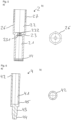
Figur 1- die schematische Darstellung eines Rückflussverhindererventils im Längsschnitt mit angedeuteter Armatur in geöffneter Position (Rückschlagkolben eingefahren);
Figur 2- die Darstellung des Rückflussverhindererventils aus
Figur 1 Figur 3- die Darstellung des Rückflussverhindererventils aus
Figur 2 Figur 4- die Darstellung des Kopfstückes des Rückflussverhindererventils Ventils aus
Figur 1- a) im Längsschnitt;
- b) in der Draufsicht;
Figur 5- die Darstellung des Druckzylinders des Rückflussverhindererventils aus
Figur 1- a) im Längsschnitt;
- b) in der Draufsicht;
Figur 6- die Darstellung des Rückschlagkolbens des Rückflussverhindererventils aus
Figur 1- a) im Längsschnitt;
- b) in der Draufsicht;
Figur 7- die Darstellung des Pumpkolbens des Rückflussverhindererventils aus
Figur 1- a) im Teilschnitt;
- b) in der Draufsicht;
- c) in der Ansicht von unten;
Figur 8- die schematische Darstellung der Spindel des Rückflussverhindererventils aus
Figur 1 - a) im Längsschnitt;
- b) in der Draufsicht;
- Figur 9
- die schematische Darstellung des Trägerstücks der Gewindeglocke des Rückflussverhindererventils aus
Figur 1 - a) im Längsschnitt;
- b) in der Draufsicht;
- Figur 10
- die schematische Darstellung der Gewindehülse der Gewindeglocke des Rückflussverhindererventils aus
Figur 1 - a) im Längsschnitt;
- b) in der Draufsicht;
Figur 11- die Darstellung der Kegelscheibe des Rückflussverhindererventils aus
Figur 1 - a) im Längsschnitt;
- b) in der Draufsicht;
Figur 12- die Darstellung der Kragenmutter des Rückflussverhindererventils aus
Figur 1 - a) im Längsschnitt;
- b) in der Draufsicht;
Figur 13- die Darstellung des Gleitrings des Rückflussverhindererventils aus
Figur 1 - a) im Längsschnitt;
- b) in der Draufsicht;
- Figure 1
- the schematic representation of a non-return valve in longitudinal section with an indicated valve in the open position (non-return piston retracted);
- Figure 2
- the representation of the non-return valve
Figure 1 in closed position (non-return piston extended) - Figure 3
- the representation of the non-return valve
Figure 2 in closed position (pressure cylinder extended); - Figure 4
- the representation of the head piece of the backflow preventer valve
Figure 1 - a) in longitudinal section;
- b) in top view;
- Figure 5
- the representation of the pressure cylinder of the non-return valve
Figure 1 ;- a) in longitudinal section;
- b) in top view;
- Figure 6
- the representation of the check piston of the non-return valve
Figure 1 - a) in longitudinal section;
- b) in top view;
- Figure 7
- the representation of the pump piston of the non-return valve
Figure 1 - a) in partial section;
- b) in top view;
- c) in the view from below;
- Figure 8
- the schematic representation of the spindle of the non-return valve
Figure 1 - a) in longitudinal section;
- b) in top view;
- Figure 9
- the schematic representation of the support piece of the threaded bell of the non-return valve
Figure 1 - a) in longitudinal section;
- b) in top view;
- Figure 10
- the schematic representation of the threaded sleeve of the threaded bell of the non-return valve
Figure 1 - a) in longitudinal section;
- b) in top view;
- Figure 11
- the representation of the conical pulley of the non-return valve
Figure 1 - a) in longitudinal section;
- b) in top view;
- Figure 12
- the representation of the collar nut of the non-return valve
Figure 1 - a) in longitudinal section;
- b) in top view;
- Figure 13
- the representation of the sliding ring of the non-return valve
Figure 1 - a) in longitudinal section;
- b) in top view;
Das als Ausführungsbeispiel gewählte Rückflussverhindererventil besteht im Wesentlichen aus einem Kopfstück 1, das von einem Druckzylinder 2 durchdrungen ist, das einen Pumpkolben 3 aufnimmt und in dem ein Rückschlagkolben 4 angeordnet ist, an dem eine Kegelscheibe 6 befestigt ist, wobei der Druckzylinder 2 und der Pumpkolben 3 über eine Spindel 5 mit einem Handrad 57 verbunden sind, über die sie axial in dem Kopfstück 1 in zueinander entgegengesetzte Richtungen verschiebbar sind.The backflow preventer valve chosen as an exemplary embodiment essentially consists of a
Das Kopfstück 1 ist ein weitgehend hohlzylindrisch ausgeführtes Messingdrehteil. An seinem unteren, armaturseitigen Ende ist an dem Kopfstück 1 ein erstes Außengewinde 11 angebracht, welches von einem umlaufenden Kragen 12 begrenzt ist. An den Kragen 12 schließt sich ein Außensechskant 13 an, der in einen außendurchmesserverjüngten Abschnitt übergeht, an dessen Ende ein zweites Außengewinde 14 zur Aufnahme der Gewindehülse 77 der Gewindeglocke 7 eingebracht ist. Im Ausführungsbeispiel ist das Außengewinde 14 als Trapezrechtsgewinde ausgeführt. Innen ist in das Kopfstück 1 in Höhe des zweiten Außengewindes 14 ein Innensechskantkragen 15 zur Führung und Verdrehsicherung des Druckzylinders 2 eingebracht. An seiner dem ersten Außengewinde 11 entgegengesetzten Innenseite sind in das Kopfstück 1 parallel zueinander zwei Nuten 16 zur Aufnahme von O-Ringen 17 eingebracht. Außen ist an dem Kopfstück 1 unterhalb des Kragens 12 ein O-Ring 18 zur Abdichtung gegenüber einer Armatur 9 angeordnet.The
Der Druckzylinder 2 ist als im Wesentlichen hohlzylinderförmig ausgebildetes Messingdrehteil ausgeführt und weist einen zylindrischen ersten Kolbenraum 21 und einen diesem gegenüber durchmessererweiterten zylindrischen zweiten Kolbenraum 22 auf, die über einen Durchgangskanal 23 miteinander verbunden sind. Der Durchgangskanal 23 ist an seinem dem ersten Kolbenraum 21 zugewandten Ende mit einer Durchmessererweiterung 231 versehen, in die umlaufend über dessen Innenmantelfläche eingebrachte, axiale über die gesamte Länge verlaufende Kerben 232 münden, wodurch eine verdrehsichernde Führung in Art eines Innensechskants erzielt ist.The
Der erste Kolbenraum 21 des Druckzylinders 2 weist an seinem dem Durchgangskanal 23 gegenüberliegenden Ende einen durchmessererweiterten Absatz 24 zur Aufnahme eines Gleitrings 25 auf, über den der Rückschlagkolben 4 in dem ersten Kolbenraum 21 verschiebbar geführt ist. Außen ist an dem Druckzylinder 2 im Bereich des zweiten Kolbenraums 21 ein sechskantförmiger Abschnitt 26 vorhanden, an den sich ein Außengewinde 27 anschließt, das im Ausführungsbeispiel als Trapezlinksgewinde ausgeführt ist. Die Außenkontur des sechskantförmigen Abschnitts 26 entspricht im Wesentlichen der Innenkontur des Innensechskantkragens 15 des Kopfstücks 1, durch den er geführt ist.The
Der Pumpkolben 3 weist einen zylindrischen Kolbenabschnitt 31 auf, der außen umlaufend mit zwei beabstandet zueinander angeordneten Nuten 32 versehen ist, in die jeweils ein O-Ring 33 zur Abdichtung gegenüber dem zweiten Kolbenraum 22 des Druckzylinders 2 eingebracht ist. Auf seiner der Spindel 5 zugewandten Seite geht der Kolbenabschnitt 31 zentrisch in eine Antriebsstange 34 über, die endseitig einen durchmessererweiterten Abschnitt 35 aufweist, der mit einem Außengewinde 36 versehen ist, das als Trapezrechtsgewinde ausgebildet ist und über das die Antriebsstange 34 mit der Spindel 5 verbunden ist. Die Antriebsstange 34 umgebend ist in den Kolbenabschnitt 31 eine Ringnut 37 eingebracht. An seiner der Antriebsstange 34 gegenüberliegenden Unterseite geht der Kolbenabschnitt 31 in eine zentrische Führungsstange 38 mit sechseckigem Querschnitt über, mit dem sie in dem Durchgangskanal 23 des Druckzylinders 2 verdrehsicher geführt ist, den sie durchdringt.The
Die Spindel 5 ist als im Wesentlichen zylinderförmig ausgebildetes Messingdrehteil ausgeführt. Die Spindel 5 ist unterteilt in einen zylindrischen Abschnitt 51 und einen vierkantförmig ausgebildeten Abschnitt 52, zwischen denen ein umlaufender Kragen 53 angeordnet ist, auf dem ein Sechskantabsatz 531 angeordnet ist. In den zylindrischen Abschnitt 51 ist in die Spindel 5 zentrisch eine erste axiale Gewindebohrung 54 eingebracht, die im Ausführungsbeispiel ein Trapezrechtsgewinde aufweist, in das die Antriebsstange 34 des Pumpkolbens 3 mit ihrem Außengewinde 36 eingreift. In den vierkantförmigen Abschnitt 52 ist zentrisch eine zweite axiale Gewindebohrung 55 eingebracht, das ein metrisches Innengewinde aufweist. Die Gewindebohrung 55 dient der Aufnahme einer Schraube 56 zur Befestigung des auf den Vierkantabschnitt 52 aufgesteckten Handrades 57.The
Zwischen Druckzylinder 2 und Handrad 57 ist auf die Spindel 5 eine Gewindeglocke 7 aufgebracht. Die Gewindeglocke 7 ist im Ausführungsbeispiel gebildet aus einem Trägerstück 71 und einer Gewindehülse 77. Das Trägerstück 71 ist als im Wesentlichen topfförmiges Messingdrehteil ausgebildet und weist eine kreisrunde Scheibe 72 auf, auf der ein hohlzylindrischer Ansatz 74 angeordnet ist, den sie umlaufend überragt. In die Scheibe 72 ist eine sechskantförmige Ausnehmung 73 eingebracht, mit der das Trägerstück 71 der Gewindeglocke 7 auf dem Sechskantabschnitt 531 des Kragens 53 der Spindel 5 aufliegt. Die Gewindeglocke 7 ist so formschlüssig mit der Spindel 5 verbunden.A threaded
Der Ansatz 74 ist innen mit einen ersten Innengewinde 75 versehen, das zum Eingriff mit dem Außengewinde 27 des Druckzylinders 2 als Trapezlinksgewinde ausgebildet ist. Außen weist der Ansatz 74 ein als Trapezrechtsgewinde ausgeführtes Außengewinde 76 auf. Die Gewindehülse 77 ist als hohlzylindrisches Messingdrehteil ausgebildet und mit einen zweiten Innengewinde 78 versehen, das als Trapezrechtsgewinde ausgebildet ist. Die Gewindehülse 77 ist mit ihrem zweiten Innengewinde 78 auf das Außengewinde 76 des Ansatzes 74 des Trägerstücks 71 aufgeschraubt und mit diesem verklebt, wobei es den Ansatz 74 des Trägerstücks 71 etwa mit seiner halben Länge axial überragt. Alternativ zur Verklebung ist auch eine thermische und/oder mechanische nicht lösbare Verbindung von Trägerstück 71 und Gewindehülse 72 möglich.The
Die so gebildete Gewindeglocke 7 weist axial und radial versetzt zueinander ein erstes, als Trapezlinksgewinde ausgebildetes, erstes Innengewinde 75 zum Eingriff mit dem Außengewinde 27 des Druckzylinders 2 und ein als Trapezrechtsgewinde ausgebildetes, zweites Innengewinde 78 zum Eingriff mit dem zweiten Außengewinde 14 des Kopfstücks 1 auf. Durch eine Drehung der Spindel 5 über das Handrad 57 ist so eine axiale Bewegung des Druckzylinders 2 entlang der Gewindeglocke 7 sowie der Gewindeglocke 7 entlang des Kopfstücks 1 in dieselbe Richtung bewirkt.The
Der Rückschlagkolben 4 ist im Wesentlichen als zylinderförmiges Messingdrehteil ausgeführt. An seinem dem Durchgangskanal 23 des Druckzylinders 2 zugewandten Ende ist in den Rückschlagkolben 4 axial eine Sackbohrung 41 zur Aufnahme einer Feder 8 eingebracht. An seinem der Spindel 5 zugewandten Ende ist an den Rückschlagkolben 4 außen ein Außenvielkant 42 angeordnet. Zwischen dem Rückschlagkolben 4 und dem zylindrischen ersten Kolbenraum 21 ist so ein Zwischenraum für den Durchtritt von Wasser gebildet. An seinem dem Außenvielkant 42 entgegengesetzten Ende weist der Rückschlagkolben 4 einen Stift 43 zur Aufnahme der Kegelscheibe 6 auf, der endseitig in einen Gewindekopf 44 übergeht.The
Die Außenmantelfläche des Rückschlagkolbens 4 ist in dem gesamten innerhalb des ersten Kolbenraums 21 des Druckzylinders 2 axial verschiebbaren Bereich, das heißt von dem Außenvielkant 42 bis zum Stift 43, mit einer Teflonschicht versehen. Alternativ kann der Rückschlagkolben 4 auch aus einem nicht korrodierenden Material wie beispielsweise Edelstahl hergestellt sein. Im Bereich der Sackbohrung 41 sind in den Rückschlagkolben 4 Druckausgleichsbohrungen 45 eingebracht, die dem Eintritt oder dem Austritt von Wasser bei Bewegung des Rückschlagkolbens 4 innerhalb des ersten Kolbenraumes 21 dienen. Die Druckausgleichsbohrungen 45 münden in dem zwischen dem Rückschlagkolben 4 und dem zylindrischen ersten Kolbenraum 21 gebildeten Zwischenraum.The outer lateral surface of the
Auf dem Stift 43 des Rückschlagkolbens 4 ist die Kegelscheibe 6 aufgeschoben. Die Kegelscheibe 6 ist im Ausführungsbeispiel als Messingdrehteil ausgeführt. An ihrer dem Kopfstück 1 abgewandten Seite ist an die Kegelscheibe 6 ein kegelförmiger Absatz 61 angeordnet. Auf ihrer dem kegelförmigen Absatz 61 gegenüberliegenden Seite weist die Kegelscheibe 6 einen durchmesserreduzierten Abschnitt 62 auf. Zentrisch ist die Kegelscheibe 6 mit einer Stufenbohrung 63 versehen, welche im Bereich des Übergangs zum durchmesserreduzierten Abschnitt 62 durchmessererweitert ausgebildet ist, wodurch ein Absatz 64 zur Aufnahme eines O-Rings 65 gebildet ist.The
Auf den kegelförmigen Absatz 61 der Kegelscheibe 6 ist eine Dichtscheibe 66 aufgelegt und Kegelscheibe 6 und Dichtscheibe 66 sind mittels einer Kragenmutter 46, die auf den Gewindekopf 44 des Stiftes 43 aufgeschraubt ist, an dem Rückschlagkolben 4 befestigt. Die Kegelscheibe 6 ist über den O-Ring 65 gegenüber dem Stift 43 des Rückschlagkolbens 4 abgedichtet.A
In montiertem Zustand ist die Spindel 5 mit ihrer ersten Gewindebohrung 54 auf das Außengewinde 36 der Antriebsstange 34 des Pumpkolbens 3 aufgeschraubt, der in den zweiten Kolbenraum 22 des Druckzylinders eingesetzt ist, wobei sein Kolbenabschnitt 31 über die O-Ringe 33 gegenüber dem zweiten Kolbenraum 22 abgedichtet ist und seine Führungsstange 38 durch den Durchgangskanal 23 des Druckzylinders 2 in den ersten Kolbenraum 21 hineinragt. Auf den Kragen 53 der Spindel 5 ist die Gewindeglocke 7 aufgesteckt, die auf dem Kragen 53 aufliegt, wobei der Sechskantabsatz 531 des Kragens in die sechskantförmige Ausnehmung 73 der Scheibe 72 eingreift, wodurch die Gewindeglocke 7 und mit der Spindel 5 formschlüssig verbunden ist. Auf den Vierkantabschnitt 52 der Spindel 5 ist das Handrad 57 aufgesteckt und über die Schraube 56, die in die zweite Gewindebohrung 55 der Spindel 5 eingeschraubt ist, mit dieser verbunden. Die Gewindeglocke 7, die über das Handrad 57 auf der Spindel 5 axial fixiert ist, ist mit ihrem ersten Innengewinde 75 mit dem Außengewinde 27 des Druckzylinders 2 und mit ihrem zweiten Innengewinde 78 mit dem zweiten Außengewinde 14 des Kopfstücks 1 im Eingriff.In the assembled state, the
Der Rückschlagkolben 4 ist mit seinem Außenvielkant 42 in den zylindrischen ersten Kolbenraum 21 des Druckzylinders 2 eingeschoben, wobei in den Rückschlagkolben 4 eine Feder 8 eingebracht ist, die als Druckspiralfeder ausgebildet ist und die mit ihrem anderen Ende an dem Grund des ersten Kolbenraums 21 des Druckzylinders 2 die Durchmessererweiterung 231 des Durchgangskanals 23 umgebend anliegt, gegen den sie vorgespannt ist. Die Führungsstange 38 ragt in die Sackbohrung 41 des Rückschlagkolbens 4 und die in diesem angeordnete Feder 8 ein. Der Rückschlagkolben 4 ist in dem Druckzylinder 2 über den Gleitring 25 geführt, der zum Wasserdurchtritt für einen Druckausgleich einen Druckausgleichsspalt 251 aufweist.The
Der Druckzylinder 2 ist über die beiden O-Ringe 17 gegenüber dem Kopfstück 1 abgedichtet, das mit seinem ersten Außengewinde 11 in eine - in den Figuren lediglich schematisch dargestellte - Armatur 9 eingeschraubt ist. Das Kopfstück 1 ist über den O-Ring 18 gegenüber der Armatur 9 abgedichtet.The
Die Armatur 9 umfasst einen Wasserzulauf 91 und einen Wasserablauf 93. Der Wasserzulauf 91 weist einen Anschlag 92 auf, an dem die an dem Rückschlagkolben 4 befestigte Dichtscheibe 66 anliegt. Der Rückschlagkolben 4 ist dabei über die Feder 8 gegen den Anschlag 92 vorgespannt. Dabei strömt kein Wasser vom Wasserzulauf 91 zum Wasserablauf 93.The fitting 9 includes a
In
In der Stellung des Rückflussverhindererventils gemäß
Ist der Wasserablauf 93 versperrt, beispielsweise über ein - nicht dargestelltes - Absperrventil im Zuge eines Wechsels einer Wasseruhr, steigt der Druck p im Wasserablauf 93 an. Bei einer Bewegung des Druckzylinders 2 durch Drehung der Spindel 5 über das Handrad 57 in Richtung der Kegelscheibe 6 zum Versperren des Wasserzulaufs 91 wird durch den zum Gewindeeingriff zwischen Gewindeglocke 7 und Druckzylinder 2 gegenläufigen Gewindeeingriff zwischen Spindel 5 und Antriebsstange 34 zugleich der Kolbenabschnitt 31 des Pumpkolbens 3 nach oben in Richtung Spindel 5 bewegt, wodurch das durch den Druckzylinder 2 verdrängte Wasser durch den Druckausgleichsspalt 251 des Gleitrings 25 über den zwischen Rückschlagkolben 4 und erstem Kolbenraum 21 gebildeten Zwischenraum durch den Durchgangskanal 23 hindurch in den zweiten Kolbenraum 22 gesaugt wird. Durch die in dem Kolbenabschnitt 31 angeordnete Ringnut 37 ist das in dem zweiten Kolbenraum 22 hierfür zur Verfügung stehende Volumen maximiert. Durch die Durchmessererweiterung 231 des Durchgangskanals 23 ist sichergestellt, dass ein Wasserfluss um die durch den Durchgangskanal 23 geführte Führungsstange 38 herum jederzeit gewährleistet ist. Der in dem Wasserablauf 93 vorhandene Druck p bleibt so annähernd konstant. Der durch die Herausbewegung des Rückschlagkolbens 4 aus dem ersten Kolbenraum 21 bewirkte Unterdruck in der Sackbohrung 41 wird durch die in dieser angeordnete Druckausgleichsbohrung 45 ausgeglichen.If the
Wird bei einer gegenläufigen Bewegung des Handrades der Druckzylinders 2 zur Freigabe des Wasserzulaufs 91 in Richtung der Spindel 5 bewegt, so wird zugleich der Kolbenabschnitt 31 des Pumpkolbens 3 nach unten in Richtung des Grundes des zweiten Kolbenraums 22 bewegt, wodurch das hier befindliche Wasser durch den Durchgangskanal 23 über den zwischen Rückschlagkolben 4 und erstem Kolbenraum 21 gebildeten Zwischenraum durch den Druckausgleichsspalt 251 des Gleitrings 25 hindurch in den Wasserablauf gedrückt wird.If the
Der in dem Wasserablauf 93 vorhandene Druck p bleibt so wiederum annähernd konstant. Der durch die Hineinbewegung des Rückschlagkolbens 4 in den ersten Kolbenraum 21 bewirkte Überdruck in der Sackbohrung 41 wird wiederum durch die in dieser angeordnete Druckausgleichsbohrung 45 ausgeglichen.The pressure p present in the
Claims (10)
- Backflow preventer valve having a head piece (1), in which a pressure cylinder (2) is arranged, which is connected to a spindle (5), via the rotation of which the pressure cylinder (2) is displaceable in the head piece (1) and which receives a non-return piston (4), which is displaceably arranged in a first piston chamber (21) of the pressure cylinder (2) and which is provided with a sealing arrangement at the end, characterised in that the pressure cylinder (2) comprises a pressure compensation pump, which is operated via the spindle (5).
- Backflow preventer valve according to claim 1, characterised in that the pressure compensation pump is formed by a second piston chamber (22) of the pressure cylinder (22), which is connected to the first piston chamber (21) via a through channel (23) and in which a pump piston (3) is displaceably arranged, which is connected via a threaded engagement to the spindle (5), via the rotation of which it is displaceable.
- Backflow preventer valve according to claim 1 or 2, characterised in that the non-return piston (4) is guided in the first piston chamber (21) via a sliding ring (25), which is provided with a pressure compensation gap (251).
- Backflow preventer valve according to claim 2 or 3, characterised in that the pump piston (3) has a guide rod (38), which projects through the through channel (23).
- Backflow preventer valve according to claim 4, characterised in that the non-return piston (4) has an axial blind hole (41), in which the guide rod (38) engages in a position of the non-return piston (4) retracted into the first piston chamber (21), wherein a radial pressure compensation bore (45) is preferably provided in the non-return valve (4), which opens into the axial blind hole (41).
- Backflow preventer valve according to claim 5, characterised in that in the axial blind hole (41) of the non-return piston (4) a spring (8) is arranged, which is pretensioned against the pressure cylinder (2).
- Backflow preventer valve according to one of claims 2 to 6, characterised in that the pump piston (3) has a drive rod (34), which is in threaded engagement with the spindle (5), wherein the drive rod (34) preferably has an external thread (36), which engages in a threaded bore (54) provided in the spindle (5).
- Backflow preventer valve according to one of the previous claims, characterised in that the spindle (5) is non-rotatably connected to a threaded bell (7), which has a first internal thread (75), which engages with an external thread (14) arranged on the outside of the head piece (1).
- Backflow preventer valve according to claim 8, characterised in that a section of reduced inner diameter is arranged in the threaded bell (7) axially upstream of the first internal thread (75), which section has a second internal thread (78), which engages with an external thread (27) arranged on the outside of the pressure cylinder (2), wherein preferably the first internal thread (75) is a right-hand thread and the second internal thread (78) is a left-hand thread.
- Backflow preventer valve according to claim 9, characterised in that the threaded bell (7) is formed by a cup-shaped carrier piece (71), which has a hollow-cylindrical extension (74), which has the second internal thread (78) and which is provided with an external thread (76), onto which a threaded sleeve (77), which has the first internal thread (75), is screwed and bonded and projects beyond the latter in length.
Priority Applications (1)
| Application Number | Priority Date | Filing Date | Title |
|---|---|---|---|
| EP22155598.0A EP4224042B1 (en) | 2022-02-08 | 2022-02-08 | Backflow preventer valve |
Applications Claiming Priority (1)
| Application Number | Priority Date | Filing Date | Title |
|---|---|---|---|
| EP22155598.0A EP4224042B1 (en) | 2022-02-08 | 2022-02-08 | Backflow preventer valve |
Publications (2)
| Publication Number | Publication Date |
|---|---|
| EP4224042A1 EP4224042A1 (en) | 2023-08-09 |
| EP4224042B1 true EP4224042B1 (en) | 2024-03-13 |
Family
ID=80448576
Family Applications (1)
| Application Number | Title | Priority Date | Filing Date |
|---|---|---|---|
| EP22155598.0A Active EP4224042B1 (en) | 2022-02-08 | 2022-02-08 | Backflow preventer valve |
Country Status (1)
| Country | Link |
|---|---|
| EP (1) | EP4224042B1 (en) |
Family Cites Families (3)
| Publication number | Priority date | Publication date | Assignee | Title |
|---|---|---|---|---|
| US4164959A (en) * | 1977-04-15 | 1979-08-21 | The Salk Institute For Biological Studies | Metering valve |
| DE102009054010B4 (en) | 2009-11-19 | 2012-02-23 | Flühs Drehtechnik GmbH | Valve top |
| DE202021101378U1 (en) | 2021-03-18 | 2021-04-07 | Flühs Drehtechnik GmbH | Backflow preventer valve |
-
2022
- 2022-02-08 EP EP22155598.0A patent/EP4224042B1/en active Active
Also Published As
| Publication number | Publication date |
|---|---|
| EP4224042A1 (en) | 2023-08-09 |
Similar Documents
| Publication | Publication Date | Title |
|---|---|---|
| EP1725796B1 (en) | Non-return valve | |
| DE2435911A1 (en) | PRESSURE DEPENDENT VALVE | |
| DE3627865A1 (en) | CHECK VALVE | |
| EP0831245B1 (en) | Industrial shock absorber | |
| EP0061415A1 (en) | Valve for hydraulic systems | |
| EP4060210A1 (en) | Backflow preventer valve | |
| DE3831554C2 (en) | Throttle check valve | |
| DE19602796B4 (en) | Control valve for small flow | |
| EP3366959B1 (en) | Upper part of a valve | |
| DE4025488C2 (en) | check valve | |
| DE202022100701U1 (en) | non-return valve | |
| EP4224042B1 (en) | Backflow preventer valve | |
| DE10014191B4 (en) | control valve | |
| EP1001196B1 (en) | Pressure limitting valve, especially for vehicles | |
| DE10356598B3 (en) | Locking cylinder for hydraulically actuated component has spindle axially movable relative to cylinder and fixed to support body | |
| EP1428962A1 (en) | Piston-cylinder unit | |
| EP0093783B1 (en) | Through-flow valve | |
| EP4286723A1 (en) | Shut-off valve | |
| DE4417293A1 (en) | Proportional pressure regulating valve | |
| DE202023101162U1 (en) | Operating device for a valve top part for sanitary fittings | |
| CH703392B1 (en) | Valve for limiting the pressure as well as with a device such. | |
| DE202022103021U1 (en) | shut-off valve | |
| DE202023101160U1 (en) | Upper valve part for sanitary fittings | |
| DE202023101163U1 (en) | Upper valve part for sanitary fittings | |
| DE3620242A1 (en) | Pilot valve, in particular 3/2 way valve |
Legal Events
| Date | Code | Title | Description |
|---|---|---|---|
| PUAI | Public reference made under article 153(3) epc to a published international application that has entered the european phase |
Free format text: ORIGINAL CODE: 0009012 |
|
| STAA | Information on the status of an ep patent application or granted ep patent |
Free format text: STATUS: REQUEST FOR EXAMINATION WAS MADE |
|
| 17P | Request for examination filed |
Effective date: 20221024 |
|
| AK | Designated contracting states |
Kind code of ref document: A1 Designated state(s): AL AT BE BG CH CY CZ DE DK EE ES FI FR GB GR HR HU IE IS IT LI LT LU LV MC MK MT NL NO PL PT RO RS SE SI SK SM TR |
|
| GRAP | Despatch of communication of intention to grant a patent |
Free format text: ORIGINAL CODE: EPIDOSNIGR1 |
|
| STAA | Information on the status of an ep patent application or granted ep patent |
Free format text: STATUS: GRANT OF PATENT IS INTENDED |
|
| INTG | Intention to grant announced |
Effective date: 20230925 |
|
| GRAS | Grant fee paid |
Free format text: ORIGINAL CODE: EPIDOSNIGR3 |
|
| GRAA | (expected) grant |
Free format text: ORIGINAL CODE: 0009210 |
|
| STAA | Information on the status of an ep patent application or granted ep patent |
Free format text: STATUS: THE PATENT HAS BEEN GRANTED |
|
| AK | Designated contracting states |
Kind code of ref document: B1 Designated state(s): AL AT BE BG CH CY CZ DE DK EE ES FI FR GB GR HR HU IE IS IT LI LT LU LV MC MK MT NL NO PL PT RO RS SE SI SK SM TR |
|
| REG | Reference to a national code |
Ref country code: GB Ref legal event code: FG4D Free format text: NOT ENGLISH |
|
| REG | Reference to a national code |
Ref country code: CH Ref legal event code: EP |
|
| REG | Reference to a national code |
Ref country code: DE Ref legal event code: R096 Ref document number: 502022000590 Country of ref document: DE |