EP1428962A1 - Piston-cylinder unit - Google Patents
Piston-cylinder unit Download PDFInfo
- Publication number
- EP1428962A1 EP1428962A1 EP03026343A EP03026343A EP1428962A1 EP 1428962 A1 EP1428962 A1 EP 1428962A1 EP 03026343 A EP03026343 A EP 03026343A EP 03026343 A EP03026343 A EP 03026343A EP 1428962 A1 EP1428962 A1 EP 1428962A1
- Authority
- EP
- European Patent Office
- Prior art keywords
- piston
- unit according
- cylinder unit
- cylinder
- stepped
- Prior art date
- Legal status (The legal status is an assumption and is not a legal conclusion. Google has not performed a legal analysis and makes no representation as to the accuracy of the status listed.)
- Granted
Links
- 239000012530 fluid Substances 0.000 claims abstract description 13
- 238000007789 sealing Methods 0.000 claims description 36
- 238000013016 damping Methods 0.000 claims description 27
- 230000006835 compression Effects 0.000 claims description 10
- 238000007906 compression Methods 0.000 claims description 10
- 238000006073 displacement reaction Methods 0.000 claims description 5
- 229920001971 elastomer Polymers 0.000 claims description 4
- 239000000806 elastomer Substances 0.000 claims description 4
- 239000013536 elastomeric material Substances 0.000 claims description 3
- 230000002093 peripheral effect Effects 0.000 description 3
- 238000004519 manufacturing process Methods 0.000 description 2
- 230000004913 activation Effects 0.000 description 1
- 230000004888 barrier function Effects 0.000 description 1
- 238000005553 drilling Methods 0.000 description 1
- 230000000977 initiatory effect Effects 0.000 description 1
- 238000009434 installation Methods 0.000 description 1
- 239000007788 liquid Substances 0.000 description 1
- 239000000463 material Substances 0.000 description 1
- 238000003466 welding Methods 0.000 description 1
Images


Classifications
-
- F—MECHANICAL ENGINEERING; LIGHTING; HEATING; WEAPONS; BLASTING
- F16—ENGINEERING ELEMENTS AND UNITS; GENERAL MEASURES FOR PRODUCING AND MAINTAINING EFFECTIVE FUNCTIONING OF MACHINES OR INSTALLATIONS; THERMAL INSULATION IN GENERAL
- F16F—SPRINGS; SHOCK-ABSORBERS; MEANS FOR DAMPING VIBRATION
- F16F9/00—Springs, vibration-dampers, shock-absorbers, or similarly-constructed movement-dampers using a fluid or the equivalent as damping medium
- F16F9/32—Details
- F16F9/50—Special means providing automatic damping adjustment, i.e. self-adjustment of damping by particular sliding movements of a valve element, other than flexions or displacement of valve discs; Special means providing self-adjustment of spring characteristics
- F16F9/512—Means responsive to load action, i.e. static load on the damper or dynamic fluid pressure changes in the damper, e.g. due to changes in velocity
-
- E—FIXED CONSTRUCTIONS
- E05—LOCKS; KEYS; WINDOW OR DOOR FITTINGS; SAFES
- E05C—BOLTS OR FASTENING DEVICES FOR WINGS, SPECIALLY FOR DOORS OR WINDOWS
- E05C17/00—Devices for holding wings open; Devices for limiting opening of wings or for holding wings open by a movable member extending between frame and wing; Braking devices, stops or buffers, combined therewith
- E05C17/02—Devices for holding wings open; Devices for limiting opening of wings or for holding wings open by a movable member extending between frame and wing; Braking devices, stops or buffers, combined therewith by mechanical means
- E05C17/04—Devices for holding wings open; Devices for limiting opening of wings or for holding wings open by a movable member extending between frame and wing; Braking devices, stops or buffers, combined therewith by mechanical means with a movable bar or equivalent member extending between frame and wing
- E05C17/30—Devices for holding wings open; Devices for limiting opening of wings or for holding wings open by a movable member extending between frame and wing; Braking devices, stops or buffers, combined therewith by mechanical means with a movable bar or equivalent member extending between frame and wing of extensible, e.g. telescopic, construction
- E05C17/305—Devices for holding wings open; Devices for limiting opening of wings or for holding wings open by a movable member extending between frame and wing; Braking devices, stops or buffers, combined therewith by mechanical means with a movable bar or equivalent member extending between frame and wing of extensible, e.g. telescopic, construction with hydraulic locks
-
- F—MECHANICAL ENGINEERING; LIGHTING; HEATING; WEAPONS; BLASTING
- F16—ENGINEERING ELEMENTS AND UNITS; GENERAL MEASURES FOR PRODUCING AND MAINTAINING EFFECTIVE FUNCTIONING OF MACHINES OR INSTALLATIONS; THERMAL INSULATION IN GENERAL
- F16F—SPRINGS; SHOCK-ABSORBERS; MEANS FOR DAMPING VIBRATION
- F16F9/00—Springs, vibration-dampers, shock-absorbers, or similarly-constructed movement-dampers using a fluid or the equivalent as damping medium
- F16F9/06—Springs, vibration-dampers, shock-absorbers, or similarly-constructed movement-dampers using a fluid or the equivalent as damping medium using both gas and liquid
- F16F9/064—Units characterised by the location or shape of the expansion chamber
-
- F—MECHANICAL ENGINEERING; LIGHTING; HEATING; WEAPONS; BLASTING
- F16—ENGINEERING ELEMENTS AND UNITS; GENERAL MEASURES FOR PRODUCING AND MAINTAINING EFFECTIVE FUNCTIONING OF MACHINES OR INSTALLATIONS; THERMAL INSULATION IN GENERAL
- F16F—SPRINGS; SHOCK-ABSORBERS; MEANS FOR DAMPING VIBRATION
- F16F9/00—Springs, vibration-dampers, shock-absorbers, or similarly-constructed movement-dampers using a fluid or the equivalent as damping medium
- F16F9/06—Springs, vibration-dampers, shock-absorbers, or similarly-constructed movement-dampers using a fluid or the equivalent as damping medium using both gas and liquid
- F16F9/066—Units characterised by the partition, baffle or like element
- F16F9/067—Partitions of the piston type, e.g. sliding pistons
-
- F—MECHANICAL ENGINEERING; LIGHTING; HEATING; WEAPONS; BLASTING
- F16—ENGINEERING ELEMENTS AND UNITS; GENERAL MEASURES FOR PRODUCING AND MAINTAINING EFFECTIVE FUNCTIONING OF MACHINES OR INSTALLATIONS; THERMAL INSULATION IN GENERAL
- F16F—SPRINGS; SHOCK-ABSORBERS; MEANS FOR DAMPING VIBRATION
- F16F9/00—Springs, vibration-dampers, shock-absorbers, or similarly-constructed movement-dampers using a fluid or the equivalent as damping medium
- F16F9/32—Details
- F16F9/50—Special means providing automatic damping adjustment, i.e. self-adjustment of damping by particular sliding movements of a valve element, other than flexions or displacement of valve discs; Special means providing self-adjustment of spring characteristics
- F16F9/516—Special means providing automatic damping adjustment, i.e. self-adjustment of damping by particular sliding movements of a valve element, other than flexions or displacement of valve discs; Special means providing self-adjustment of spring characteristics resulting in the damping effects during contraction being different from the damping effects during extension, i.e. responsive to the direction of movement
Definitions
- the invention relates to a piston-cylinder unit a closed cylinder in which a piston has a radial enclosing ring seal sealed against the cylinder is guided axially displaceably and in the cylinder interior divided a first and a second work space, both with a fluid, especially with a hydraulic Liquid are filled with a piston rod that passes through extends the cylinder interior and tightly through the front at least one closure wall of the cylinder to the outside is passed, with a first check valve, the Closing member is loaded in the closing direction and under one high pressure in the first work space with the first work space the second work space can be opened with a second check valve, the closing member in the closing direction under load and under high pressure in the second work area connecting the second work space with the first work space can be opened.
- Piston-cylinder units of this type are used, for example, as stepless door stops for motor vehicle doors.
- the two non-return valves are closed and the door is held in the position currently occupied. If the door is opened manually in order to be moved out of this position, this results in a pressure build-up in a working chamber and this pressure opens the valve assigned to this working chamber. Fluid can flow from this working chamber into the other working chamber. To open the valve, a pressure must be built up in the working chamber, which overcomes the force loading of the closing element in the closing direction.
- the pressure in the working chamber is reduced in such a way that the check valve also closes and the door movement is blocked by the piston-cylinder unit, even if another door movement is still desired.
- the object of the invention is therefore a piston-cylinder unit to create the type mentioned, the first and / or second check valve a lower hold-open pressure to Keeping the check valve open requires that Opening pressure to open the check valve.
- This object is achieved in that the of the pressure of the working space effective area of the Closing member of the first and / or second check valve during which opening stroke can be increased.
- Closing member is a stepped piston, which is in a corresponding Stepped bore is slidably arranged and the steps Effective pressure on the front side of the work area Have surfaces, starting in the closed position and the pressurization of the smallest stage with increasing Opening stroke of the step piston increasingly further steps of the Step piston can be pressurized.
- the end face of the smallest step can be easily of the stepped piston form the closing member, which on the one Valve seat of the check valve forming the mouth of the Working space leading smallest step of the stepped bore is attachable.
- the closing member has a cone-like closing surface that opens the valve seat can be put on, it is in the closed state of the check valve reaches a high degree of tightness, which thereby increased with lower manufacturing tolerances is when the closing member a closing surface from a Has elastomer.
- a radial can be made from the largest step of the stepped bore Connection open into an annular cylinder space, the between the inner wall of the cylinder and the radially rotating one Shell surface of the piston and formed by the ring seals is sealed off from the work rooms by its pressure the stepped piston can be acted upon in the opening direction, whereby the radial connection from the largest step of the stepped piston lockable and openable in its largest opening stroke position is.
- the fluid can flow from one cylinder chamber to the other Stream workspace.
- Closing element by a compression spring supported on the piston, in particular a helical compression spring or a plate spring in Closing direction must be loaded.
- the damping opening defines the opening time of the Check valve.
- the damping chamber is in when the stepped piston moves Closing direction can be connected to the cylinder chamber via a valve, so with a closing movement, fluid from the Cylinder space flow into the damping chamber, which is a small Check valve closing time enabled.
- This valve is particularly simple if there is one Has sealing ring which is arranged in an annular groove, the the cylindrical surface of the largest stage of the Stepped piston is formed, which is the damping chamber opposite side of the sealing ring can be connected to the cylinder space and the sealing ring from the cylinder chamber to the damping chamber or is underflow.
- the one surrounding the piston and opposite the cylinder sealing ring seal can be arranged in an annular groove, which are formed on the cylindrical surface of the piston is.
- the ring seal has a radially circumferential sealing lip with the free end directed towards the work area resiliently in contact with the inner wall of the cylinder although a fluid flow from the work space in the on the on the other side of the ring seal shut off. In the opposite direction, however, the fluid can flow easily.
- At least one step hole can pass through the through hole a tube directed towards the damping chamber, in a smaller step of the step piston can be moved is arranged, the tube from a collar-like area of the stepped piston, around which the tube radially enclosing the next larger step of the step piston is arranged.
- the tube is formed at its end region facing the damping chamber with radially continuous slots which form the radial connection between two stages of the stepped bore, then these form in a simple manner a radial connection of large cross section between two stages of the stepped bore, which results in rapid fluid flow and thus enables rapid movement of the stepped piston.
- the stepped piston consists of an elastomeric material and integrally with the closing surface of the closing member and / or with radially circumferential sealing lips on one or more Steps of the step piston is formed.
- a short length and compact design of the piston-cylinder unit is achieved in that the piston with a one-sided piston rod is provided and a Piston volume compensation chamber to accommodate the opposite of the Displacement of the working chamber on the piston rod side larger displacement of the working space remote from the piston rod has, the design of which is particularly compact can be, if the volume compensation chamber between the first and the second check valve arranged in the piston and via an inlet opening with the cylinder space between the first and the second check valve is connected.
- the throttle passage can flow from the first work space to the second work space and / or from that second work space to the first work space in front and / or behind the valve seat of the seat valve may be arranged.
- a simple way to arrange the Throttle passage in front of the valve seat is that the Step piston one from the closing member to the work area has approximately cylindrical extension directed by the smallest step of the stepped bore protrudes, with an annular gap between the peripheral surface of the extension and the Inner wall of the smallest step of the step hole Throttle passage forms.
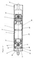
- the piston-cylinder unit shown in Figure 1 is a steplessly acting door arrester for motor vehicles. He has a cylinder 1 closed at its ends, in which a piston 2 is slidably guided, the interior of the Cylinder 1 in a piston rod-side first working space 3 and a second working space 4 remote from the piston rod. Both workrooms 3 and 4 are filled with oil.
- a piston rod 5 is arranged on one side of the piston 2, which extends through the first work space 3 and through a seal, not shown, and a likewise not shown front closure wall of the cylinder 1 tight is led to the outside.
- the piston 2 consists of a middle one Volume compensation element 6, one towards the first work space 3 adjoining first valve element 7 and one to the second Working space 4 adjoining second valve element 8.
- the volume compensation element 6, the first valve element 7 and the second valve element 8 are firmly connected to one another, the piston rod 5 also on the first valve element 7 is attached.
- the approximately pot-shaped valve elements 7 and 8 have at their respective work rooms 3 and 4 facing ends a bottom 9.
- the smallest stage 10 one coaxial in the valve element 7 and 8 formed stepped bore 11 extends through the bottom 9 and ends in the work room 3 or 4.
- the first Valve element 7 three at right angles the smallest stage 10 intersecting connecting bores 12 in the valve element 7 educated.
- the smallest stage opens at the valve element 8 10 of the stepped bore 11 directly into the working space 4.
- valve elements 7 and 8 Since the structure of the valve elements 7 and 8 is otherwise the same, the further description is based on the second Valve element 8.
- the smallest step 10 of the step bore 11 is then a second step 13 of the stepped bore 11 in the bottom 9 trained to extend them from the work space 4 directed away at the bottom 9 a coaxially into the pot opening of the Valve element 8 projecting tube 14 is formed, which its end area facing away from the working space with radial through slots 15 is formed.
- the pot opening of the Valve element 8 itself forms the largest stage 16 of the Stepped bore 11.
- the stepped bore 11 is the largest Stage 17 of a stepped piston 18 slidably arranged, the smaller stage 19 in the second stage 13 of the stepped bore 11 is movable. That for the smallest step 10 of the step hole 11 directed end of the smaller step 19 of the step piston 18th is as a closing member 20 of a check valve 26 with a conical closing surface 21 formed on a Valve seat 22 can be placed, that of the mouth of the smallest Stage 10 is formed in the second stage 13 of the stepped bore 11 is.
- the closing member 20 is a separate component an elastomeric material which on its closing surface 21st facing away from a coaxially projecting shaft 23 has, with which it is in a corresponding base bore 24 in Step piston 18 is firmly inserted.
- the second stage is 13 of the largest stage 17 of the stepped bore 11 lockable.
- This barrier consists of the first part of an opening stroke of the check valve 26 to the sealing ring 25 reaches the area of the radial slots 15 and then the lowest level 10 and the second level Stage 13 of the stepped bore 11 and thus also the second Working space 4 with the largest step 16 of the stepped bore 11 is connected.
- This opening movement of the stepped piston 11 takes place counter to the force of a prestressed helical compression spring 27 which acts on the stepped piston 11 in the closing direction when a corresponding pressure has built up in the working space 4, which first of all closes the closing surface 21 of the closing member 20 and after lifting it off the valve seat 22 End face of the smaller step 19 of the step piston 18 is applied. After driving over the slots 15 through the sealing ring 25, the surface of the largest step 17 of the step piston 18 is then also acted upon.
- the largest step 17 of the step piston 18 has a radial on it circumferential outer surface two formed at a distance from each other Ring grooves 33 and 34, in the sealing rings 35 and 36 for Sealing of the stepped piston 18 against the inner wall of the largest stage 16 of the stepped bore 11 are arranged.
- the entire piston 2 is thus in the working space 4 displaceable.
- a damping chamber 41 is formed on the side of the largest step 17 of the step piston 18 facing away from the working chamber 4, which is connected to the cylinder chamber 29 via a damping opening 42, whereby an opening movement of the step piston 18 is damped.
- the sealing ring 36 can be flowed through in the direction from the cylinder chamber 29 to the damping chamber 41, and the damping chamber 41 can thus be quickly filled with oil.
- the sealing ring 26 seals off, so that only the damping opening 42 is available as a connection between the damping chamber 41 and the cylinder chamber 29 during an opening movement.
- valve element 7 corresponds to the structure and function of the valve element 8 described.
- the step piston 18 'shown in FIG. 4 corresponds to FIG its structure and its function that in FIGS. 1 to 3 Step piston 18 shown with the difference that it as a component consists of an elastomer and in one piece with the Sealing rings 35 and 36 forming sealing lips 43 and 44, with a the sealing ring 25 forming sealing lip 45 and with which Closing surface 21 having locking member 20 is formed.
- valve element 8 shown with the volume compensation element 6.
- Valve element 8 a coaxial annular end 46 and that Volume compensation element 6 has a coaxial annular end 47 on. Both annular ends 46 and 47 have the same Outer diameter.
- the annular end 46 has at its Inner circumference a diameter-increasing ring step 48 and that annular end 47 at its outer diameter Corresponding diameter-reducing ring step 49.
- This Ring steps 48 and 49 are telescoped and connected to each other.
- a radial latching opening 50 is formed in the area of the ring step 48, into which a corresponding radially outwardly projecting latching lug 51 on the ring step 49 can be latched when the ring steps 48 and 49 are telescopically pushed into one another.
- the basic structure of the exemplary embodiment in FIG. 7 corresponds to the exemplary embodiment shown in FIG. 2, the stepped piston 18 ′′ being designed as a component consisting of an elastomer, analogously to the stepped piston 18 ′ shown in FIG.
- the stepped piston 18 ′′ has one of the closing member 20 to the working space 3 directed cylindrical extension 52, the protrudes through the smallest step 10 of the stepped bore 11.
- the between the peripheral surface of the extension 52 and the Inner wall of the smallest step 10 of the step bore 11 formed Annular gap 53 acts as a throttle passage.
Abstract
Description
Die Erfindung bezieht sich auf eine Kolben-Zylinder-Einheit mit einem geschlossenen Zylinder, in dem ein Kolben über eine radial umschließende Ringdichtung gegenüber dem Zylinder abgedichtet axial verschiebbar geführt ist und den Zylinderinnenraum in einen ersten und eine zweiten Arbeitsraum unterteilt, die beide mit einem Fluid, insbesondere mit einer hydraulischen Flüssigkeit gefüllt sind, mit einer Kolbenstange, die sich durch den Zylinderinnenraum erstreckt und stirnseitig dicht durch zumindest eine Verschlußwand des Zylinders nach außen hindurchgeführt ist, mit einem ersten Rückschlagventil, dessen Schließglied in Schließrichtung kraftbelastet und unter einem hohen Druck in dem ersten Arbeitsraum den ersten Arbeitsraum mit dem zweiten Arbeitsraum verbindend öffenbar ist, mit einem zweiten Rückschlagventil, dessen Schließglied in Schließrichtung kraftbelastet und unter einem hohem Druck im zweiten Arbeitsraum den zweiten Arbeitsraum mit dem ersten Arbeitsraum verbindend öffenbar ist.The invention relates to a piston-cylinder unit a closed cylinder in which a piston has a radial enclosing ring seal sealed against the cylinder is guided axially displaceably and in the cylinder interior divided a first and a second work space, both with a fluid, especially with a hydraulic Liquid are filled with a piston rod that passes through extends the cylinder interior and tightly through the front at least one closure wall of the cylinder to the outside is passed, with a first check valve, the Closing member is loaded in the closing direction and under one high pressure in the first work space with the first work space the second work space can be opened with a second check valve, the closing member in the closing direction under load and under high pressure in the second work area connecting the second work space with the first work space can be opened.
Derartige Kolben-Zylinder-Einheiten finden z.B. als stufenlose
Türfeststeller für Kraftfahrzeugtüren Verwendung. Dabei sind bei
unbetätigter Tür die beiden Rückschlagventile geschlossen und
die Tür in der momentan eingenommenen Stellung gehalten. Wird
die Tür manuell beaufschlagt um aus dieser Stellung herausbewegt
zu werden, kommt es dadurch zu einem Druckaufbau in einer
Arbeitskammer und durch diesen Druck zu einem Öffnen des dieser
Arbeitskammer zugeordneten Ventils. Dabei kann Fluid aus dieser
Arbeitskammer in die andere Arbeitskammer strömen.
Zum Öffnen des Ventils muß in der Arbeitskammer ein Druck
aufgebaut werden, der die Kraftbelastung des Schließglieds in
Schließrichtung überwindet. Reduziert sich die Kraft der
manuellen Beaufschlagung der Tür unter ein bestimmtes Maß, ohne
daß die Türbewegung beendet wird, reduziert sich der Druck in
der Arbeitskammer derart, daß auch das Rückschlagventil schließt
und die Türbewegung durch die Kolben-Zylinder-Einheit blockiert
wird, auch wenn eine weitere Türbewegung noch gewünscht wird.Piston-cylinder units of this type are used, for example, as stepless door stops for motor vehicle doors. When the door is not actuated, the two non-return valves are closed and the door is held in the position currently occupied. If the door is opened manually in order to be moved out of this position, this results in a pressure build-up in a working chamber and this pressure opens the valve assigned to this working chamber. Fluid can flow from this working chamber into the other working chamber.
To open the valve, a pressure must be built up in the working chamber, which overcomes the force loading of the closing element in the closing direction. If the force of the manual loading of the door is reduced to a certain extent without the door movement being ended, the pressure in the working chamber is reduced in such a way that the check valve also closes and the door movement is blocked by the piston-cylinder unit, even if another door movement is still desired.
Aufgabe der Erfindung ist es daher eine Kolben-Zylinder-Einheit der eingangs genannten Art zu schaffen, deren erstes und/oder zweiten Rückschlagventil einen geringeren Offenhaltungsdruck zum Offenhalten des Rückschlagventils erfordert, als dem Öffnungsdruck zum Öffnen des Rückschlagventils.The object of the invention is therefore a piston-cylinder unit to create the type mentioned, the first and / or second check valve a lower hold-open pressure to Keeping the check valve open requires that Opening pressure to open the check valve.
Diese Aufgabe wird erfindungsgemäß dadurch gelöst, daß die von dem Druck des Arbeitsraums wirksam beaufschlagbare Fläche des Schließglieds des ersten und/oder zweiten Rückschlagventils während dessen Öffnungshubes vergrößerbar ist.This object is achieved in that the of the pressure of the working space effective area of the Closing member of the first and / or second check valve during which opening stroke can be increased.
Da die wirksame Fläche des Schließglieds nach Öffnung des Rückschlagventils größer wird, kann das Rückschlagventil im geöffneten Zustand durch einen geringeren Druck im Arbeitsraum in der Offenstellung gehalten werden. Dies bedeutet bei der Anwendung in einem stufenlosen Türfeststeller, daß die manuell unbetätigte Tür stabil in ihrer eingenommenen Position gehalten wird und bei z.B. unbeabsichtigter leichter Kraftbeaufschlagung die Position beibehält. Wird die Tür bewußt mit einem bestimmten Kraftaufwand bewegt, so erfolgt auch ein entsprechender hoher Druckaufbau im Arbeitsraum und ein Öffnen des Rückschlagventils. Für eine weitere Öffnungsbewegung ist dann nur noch ein reduzierter Kraftaufwand erforderlich.Since the effective area of the closing member after opening the Check valve becomes larger, the check valve in the open state due to lower pressure in the work area be kept in the open position. This means at Application in a stepless door stay that the manually unactuated door held stable in its occupied position and at e.g. accidental light application of force maintains the position. The door becomes conscious with a certain one Movement requires a correspondingly high level Pressure build-up in the work area and an opening of the check valve. For a further opening movement there is only one reduced effort required.
Eine einfach aufgebaute Ausbildung besteht darin, daß das Schließglied ein Stufenkolben ist, der in einer entsprechenden Stufenbohrung verschiebbar angeordnet ist und dessen Stufen stirnseitige wirksam vom Druck des Arbeitsraums beaufschlagbare Flächen aufweisen, wobei beginnend in der Schließstellung und der Druckbeaufschlagung der kleinsten Stufe mit zunehmendem Öffnungshub des Stufenkolbens zunehmend weitere Stufen des Stufenkolbens druckbeaufschlagbar sind.A simple structure is that Closing member is a stepped piston, which is in a corresponding Stepped bore is slidably arranged and the steps Effective pressure on the front side of the work area Have surfaces, starting in the closed position and the pressurization of the smallest stage with increasing Opening stroke of the step piston increasingly further steps of the Step piston can be pressurized.
Ist zumindest die kleinste vom Druck des Arbeitsraums beaufschlagbare Fläche des Rückschlagventils ein Schließglied eines Sitzventils, so kommt es bei Erreichen des Öffnungsdrucks im Arbeitsraum zu einem schnellen Öffnen des Rückschlagventils und damit auch zu einer sofortigen Reduzierung des zum Offenhalten erforderlichen Drucks. Eine Tür kann somit nach Einleitung einer Bewegung sofort mit geringerer Kraft weiterbewegt werden.Is at least the smallest of the pressure in the work area actable area of the check valve a closing member of a seat valve, this occurs when the opening pressure is reached in the work area for a quick opening of the check valve and thus an immediate reduction in the Keeping the required pressure open. A door can therefore open Initiation of a movement immediately with less force be moved on.
Dabei kann in einfacher Weise die Stirnseite der kleinsten Stufe des Stufenkolbens das Schließglied bilden, das auf die einen Ventilsitz des Rückschlagventils bildende Mündung der zum Arbeitsraum führenden kleinsten Stufe der Stufenbohrung aufsetzbar ist.The end face of the smallest step can be easily of the stepped piston form the closing member, which on the one Valve seat of the check valve forming the mouth of the Working space leading smallest step of the stepped bore is attachable.
Besitzt das Schließglied eine kegelartige Schließfläche, die auf den Ventilsitz aufsetzbar ist, so wird im geschlossenen Zustand des Rückschlagventils ein hoher Dichtheitsgrad erreicht, der dadurch bei geringeren Herstellungstoleranzen noch vergrößert wird, wenn das Schließglied eine Schließfläche aus einem Elastomer besitzt. The closing member has a cone-like closing surface that opens the valve seat can be put on, it is in the closed state of the check valve reaches a high degree of tightness, which thereby increased with lower manufacturing tolerances is when the closing member a closing surface from a Has elastomer.
Besitzt eine oder mehrere Stufen der Stufenbohrung eine Verbindung zur nächstgrößeren Stufe, wobei bei Erreichen jeweils eines bestimmten Öffnungshubes die entsprechende Verbindung zur nächsthöheren Stufe der Stufenbohrung öffenbar ist, so erfolgt die Reduzierung des erforderlichen Offenhaltungsdrucks stufenweise und nicht plötzlich.Has one or more stages of the stepped bore Connection to the next higher level, each time it is reached a certain opening stroke the corresponding connection to the next higher step of the stepped bore can be opened, takes place the reduction of the required pressure to keep open gradually and not suddenly.
Ein einfacher Aufbau mit wenigen Bauteilen wird dadurch erreicht, daß eine oder mehrere der Stufen des Stufenkolbens einen Schieber eines Schieberventils bilden, durch den die entsprechende radial in die Stufenbohrung mündende Verbindung verschließbar ist.This makes it easy to set up with just a few components accomplished that one or more of the stages of the stepped piston form a slide of a slide valve through which the Corresponding connection opening radially into the stepped bore is lockable.
Um trotz Einhaltung geringerer Toleranzen eine gute Abdichtung zu erhalten, können eine oder mehrere der Stufen des Stufenkolbens an ihrer zylindrischen Mantelfläche eine radial umlaufende Ringnut aufweisen, in der ein Dichtring eingesetzt ist, der mit seinem radial umlaufenden äußeren Bereich dichtend an der Innenwand der entsprechenden Stufe der Stufenbohrung in Anlage ist.To ensure a good seal despite compliance with lower tolerances can get one or more of the stages of Stepped piston a radial on its cylindrical surface Have circumferential annular groove in which a sealing ring is used is the sealing with its radially circumferential outer region on the inner wall of the corresponding step of the step hole in Facility is.
Von der größten Stufe der Stufenbohrung kann eine radiale Verbindung in einen ringförmigen Zylinderraum münden, der zwischen der Innenwand des Zylinders und der radial umlaufenden Mantelfläche des Kolbens gebildet und durch die Ringdichtungen gegenüber den Arbeitsräumen abgedichtet ist, durch dessen Druck der Stufenkolben in Öffnungsrichtung beaufschlagbar ist, wobei die radiale Verbindung von der größten Stufe des Stufenkolbens verschließbar und in dessen größter Öffnungshubstellung öffenbar ist. Von dem Zylinderraum kann das Fluid zu dem anderen Arbeitsraum strömen.A radial can be made from the largest step of the stepped bore Connection open into an annular cylinder space, the between the inner wall of the cylinder and the radially rotating one Shell surface of the piston and formed by the ring seals is sealed off from the work rooms by its pressure the stepped piston can be acted upon in the opening direction, whereby the radial connection from the largest step of the stepped piston lockable and openable in its largest opening stroke position is. The fluid can flow from one cylinder chamber to the other Stream workspace.
Zur einfachen Kraftbelastung in Schließrichtung kann das Schließglied durch eine am Kolben abgestützte Druckfeder, insbesondere eine Schraubendruckfeder oder eine Tellerfeder in Schließrichtung belastet sein.For simple force loading in the closing direction, this can be done Closing element by a compression spring supported on the piston, in particular a helical compression spring or a plate spring in Closing direction must be loaded.
Zur Dämpfung der Bewegung des Stufenkolbens kann die größte Stufe der Stufenbohrung auf der der Arbeitskammer abgewandten Seite des Stufenkolbens eine Dämpfungskammer bilden, die über eine Dämpfungsöffnung mit dem Zylinderinnenraum verbunden ist. Die Dämpfungsöffnung definiert dabei die Öffnungszeit des Rückschlagventils.The largest can dampen the movement of the stepped piston Step of the step hole on the side facing away from the working chamber Form a damping chamber on the side of the stepped piston a damping opening is connected to the cylinder interior. The damping opening defines the opening time of the Check valve.
Ist die Dämpfungskammer bei Bewegung des Stufenkolbens in Schließrichtung über ein Ventil mit dem Zylinderraum verbindbar, so kann bei einer Schließbewegung schnell Fluid von dem Zylinderraum in die Dämpfungskammer strömen, was eine geringe Schließzeit des Rückschlagventils ermöglicht.The damping chamber is in when the stepped piston moves Closing direction can be connected to the cylinder chamber via a valve, so with a closing movement, fluid from the Cylinder space flow into the damping chamber, which is a small Check valve closing time enabled.
Dieses Ventil ist besonders einfach aufgebaut, wenn es einen Dichtring aufweist, der in einer Ringnut angeordnet ist, die an der zylindrischen Mantelfläche der größten Stufe des Stufenkolbens ausgebildet ist, wobei die der Dämpfungskammer abgewandte Seite des Dichtrings mit dem Zylinderraum verbindbar und der Dichtring von dem Zylinderraum zur Dämpfungskammer über- oder unterströmbar ist.This valve is particularly simple if there is one Has sealing ring which is arranged in an annular groove, the the cylindrical surface of the largest stage of the Stepped piston is formed, which is the damping chamber opposite side of the sealing ring can be connected to the cylinder space and the sealing ring from the cylinder chamber to the damping chamber or is underflow.
Ein besonderer Einbauraum ist für die Druckfeder nicht erforderlich, wenn die Druckfeder in der Dämpfungskammer angeordnet ist, so daß eine geringe Baulänge der Kolben-Zylinder-Einheit ermöglicht wird.There is no special installation space for the compression spring required if the compression spring in the damping chamber is arranged so that a small length of the piston-cylinder unit is made possible.
Um bei der Schließbewegung des Stufenkolbens ein Ausströmen des Fluids aus der größten Stufe der Stufenbohrung auch im letzten Schließhubbereich sicherzustellen, kann die größte Stufenbohrung auf der der Arbeitskammer zugewandeten Seite der entsprechenden Stufe des Stufenkolbens über eine Drosselöffnung mit dem Zylinderraum verbunden sein. To an outflow of the Fluids from the largest step of the stepped bore also in the last Ensuring the closing stroke range can be the largest stepped bore on the side of the corresponding one facing the working chamber Stage of the stepped piston with a throttle opening Be connected to the cylinder space.
Die den Kolben umschließende und gegenüber dem Zylinder abdichtende Ringdichtung kann in einer Ringnut angeordnet sein, die an der zylindrischen Mantelfläche des Kolbens ausgebildet ist.The one surrounding the piston and opposite the cylinder sealing ring seal can be arranged in an annular groove, which are formed on the cylindrical surface of the piston is.
Weist die Ringdichtung dabei eine radial umlaufende Dichtlippe auf, die mit ihrem freien Ende etwa zum Arbeitsraum gerichtet federnd an der Innenwand des Zylinders in Anlage ist, so ist zwar eine Fluidströmung von dem Arbeitsraum in den auf der anderen Seite der Ringdichtung befindlichen Zylinderraum sicher abgesperrt. In umgekehrter Richtung kann das Fluid aber problemlos strömen.If the ring seal has a radially circumferential sealing lip with the free end directed towards the work area resiliently in contact with the inner wall of the cylinder although a fluid flow from the work space in the on the on the other side of the ring seal shut off. In the opposite direction, however, the fluid can flow easily.
Zumindest eine Stufenbohrung kann durch die Durchgangsbohrung eines zur Dämpfungskammer gerichteten Rohres gebildet sein, in der eine kleinere Stufe des Stufenkolbens verschiebbar angeordnet ist, wobei das Rohr von einem kragenartigen Bereichs des Stufenkolbens umgriffen ist, an dem radial das Rohr umschließend die nächst größere Stufe des Stufenkolbens angeordnet ist. Dies führt zu einer ineinander verschachtelten Anordnung von Stufenkolben und Stufenbohrung und damit zu einer kurzen Baulänge.At least one step hole can pass through the through hole a tube directed towards the damping chamber, in a smaller step of the step piston can be moved is arranged, the tube from a collar-like area of the stepped piston, around which the tube radially enclosing the next larger step of the step piston is arranged. This leads to a nested one Arrangement of stepped piston and stepped bore and thus to one short overall length.
Ist dabei das Rohr an seinem der Dämpfungskammer zugewandten
Endbereich mit radial durchgehenden Schlitzen ausgebildet, die
die radiale Verbindung zwischen zwei Stufen der Stufenbohrung
bilden, so bilden diese auf einfache Weise eine radiale
Verbindung großen Querschnitts zwischen zwei Stufen der
Stufenbohrung, was eine schnelle Fluidströmung und damit eine
schnelle Bewegung des Stufenkolbens ermöglicht.
Eine einfache, viele Elemente in einen Bauteil zusammenfassende
Ausgestaltung und damit auch eine Reduzierung des Herstellungs-
und Montageaufwandes wird dadurch erreicht, daß der Stufenkolben
aus einem elastomeren Werkstoff besteht und einteilig mit der
Schließfläche des Schließglieds und/oder mit radial umlaufenden
Dichtlippen an einer oder mehreren Stufen des Stufenkolbens
ausgebildet ist.If the tube is formed at its end region facing the damping chamber with radially continuous slots which form the radial connection between two stages of the stepped bore, then these form in a simple manner a radial connection of large cross section between two stages of the stepped bore, which results in rapid fluid flow and thus enables rapid movement of the stepped piston.
A simple, many elements in one component design and thus a reduction in manufacturing and assembly effort is achieved in that the stepped piston consists of an elastomeric material and integrally with the closing surface of the closing member and / or with radially circumferential sealing lips on one or more Steps of the step piston is formed.
Eine kurze Baulänge und kompakte Bauweise der Kolben-Zylinder-Einheit wird dadurch erreicht, daß der Kolben mit einer einseitigen Kolbenstange versehen ist und eine Kolbenvolumenausgleichskammer zur Aufnahme der gegenüber der Verdrängungsmenge des kolbenstangenseitigen Arbeitsraumes größeren Verdrängungsmenge des kolbenstangenfernen Arbeitsraums aufweist, wobei die Bauweise besonders kompakt ausgestaltet werden kann, wenn die Volumenausgleichskammer zwischen dem ersten und dem zweiten Rückschlagventil im Kolben angeordnet und über eine Einlaßöffnung mit dem Zylinderraum zwischen dem ersten und dem zweiten Rückschlagventil verbunden ist.A short length and compact design of the piston-cylinder unit is achieved in that the piston with a one-sided piston rod is provided and a Piston volume compensation chamber to accommodate the opposite of the Displacement of the working chamber on the piston rod side larger displacement of the working space remote from the piston rod has, the design of which is particularly compact can be, if the volume compensation chamber between the first and the second check valve arranged in the piston and via an inlet opening with the cylinder space between the first and the second check valve is connected.
Um beim Öffnen des Rückschlagventils einen plötzlichen Druckabfall in dem Arbeitsraum und dadurch hervorgerufene störende Geräusche zu vermeiden, kann in einem ersten Teil des Öffnungshubes des Schließgliedes des Rückschlagventils der Ventildurchgang ein Drosseldurchgang sein.To a sudden when opening the check valve Pressure drop in the work area and thereby caused Avoiding annoying noises can be in a first part of the Opening stroke of the closing member of the check valve Valve passage may be a throttle passage.
Dabei kann der Drosseldurchgang in Strömungsrichtung von dem ersten Arbeitsraum zum zweiten Arbeitsraum und/oder von dem zweiten Arbeitsraum zum ersten Arbeitsraum vor und/oder hinter dem Ventilsitz des Sitzventils angeordnet sein.The throttle passage can flow from the first work space to the second work space and / or from that second work space to the first work space in front and / or behind the valve seat of the seat valve may be arranged.
Eine einfach aufgebaute Möglichkeit zur Anordnung des Drosseldurchgangs vor dem Ventilsitz besteht darin, daß der Stufenkolben einen von dem Schließglied zum Arbeitsraum gerichteten etwa zylindrischen Fortsatz aufweist, der durch die kleinste Stufe der Stufenbohrung ragt, wobei ein Ringspalt zwischen der umlaufenden Mantelfläche des Fortsatzes und der Innenwand der kleinsten Stufe der Stufenbohrung den Drosseldurchgang bildet. A simple way to arrange the Throttle passage in front of the valve seat is that the Step piston one from the closing member to the work area has approximately cylindrical extension directed by the smallest step of the stepped bore protrudes, with an annular gap between the peripheral surface of the extension and the Inner wall of the smallest step of the step hole Throttle passage forms.
Im gleichen Maße einfach aufgebaut ist ein hinter dem Ventilsitz angeordneter Drosseldurchgang erreichbar, wenn die in Strömungsrichtung von dem ersten Arbeitsraum zum zweiten Arbeitsraum und/oder von dem zweiten Arbeitsraum zum ersten Arbeitsraum hinter dem Ventilsitz des Sitzventils befindliche Stufe des Stufenkolbens einen etwa zylindrisch ausgebildeten Fortsatz aufweist, der in Öffnungsrichtung des Rückschlagventils durch einen in die zweite Stufe der Stufenbohrung ragenden koaxialen ringförmigen Kragen geführt ist, wobei ein Ringspalt zwischen der umlaufenden Mantelfläche des Fortsatzes und der Innenwand des ringförmigen Kragens den Drosseldurchgang bildet.To the same extent, one is behind the valve seat arranged throttle passage accessible when the in Flow direction from the first working space to the second Work space and / or from the second work space to the first Work area located behind the valve seat of the seat valve Stage of the stepped piston is approximately cylindrical Has extension that in the opening direction of the check valve through a protruding into the second stage of the stepped bore coaxial annular collar is guided, with an annular gap between the peripheral surface of the extension and the Inner wall of the annular collar forms the throttle passage.
Ausführungsbeispiele der Erfindung sind in der Zeichnung dargestellt und werden im folgenden näher beschrieben. Es zeigen
- Figur 1
- einen Querschnitt im Kolbenbereich einer Kolben-Zylinder-Einheit
Figur 2- eine vergrößerte Darstellung des Kolbens der Kolben-Zylinder-Einheit nach Figur 1 im Bereich eines Rückschlagventils im Querschnitt
Figur 3- ein erstes Ausführungsbeispiel eines
Stufenkolbens des Rückschlagventils
nach
Figur 2 im Schnitt - Figur 4
- ein zweites Ausführungsbeispiel eines
Stufenkolbens für ein
Rückschlagventil nach
Figur 2 im Schnitt Figur 5- ein erstes Ausführungsbeispiel der Verbindung von Teilen des Kolbens der Kolben-Zylinder-Einheit nach Figur 1
Figur 6- ein zweites Ausführungsbeispiel der Verbindung von Teilen des Kolbens der Kolben-Zylinder-Einheit nach Figur 1.
Figur 7- eine ein zweites Ausführungsbeispiel einer vergrößerten Darstellung eines Kolbens der Kolben-Zylinder-Einheit nach Figur 1 im Bereich eines Rückschlagventils im Querschnitt
- Figure 1
- a cross section in the piston area of a piston-cylinder unit
- Figure 2
- an enlarged view of the piston of the piston-cylinder unit according to Figure 1 in the area of a check valve in cross section
- Figure 3
- a first embodiment of a step piston of the check valve of Figure 2 in section
- Figure 4
- a second embodiment of a step piston for a check valve according to Figure 2 in section
- Figure 5
- a first embodiment of the connection of parts of the piston of the piston-cylinder unit according to Figure 1
- Figure 6
- a second embodiment of the connection of parts of the piston of the piston-cylinder unit according to Figure 1.
- Figure 7
- a second embodiment of an enlarged view of a piston of the piston-cylinder unit according to Figure 1 in the region of a check valve in cross section
Die in Figur 1 darstellte Kolben-Zylinder-Einheit ist ein
stufenlos wirkender Türfeststeller für Kraftfahrzeuge. Er
besitzt einen an seinen Enden geschlossenen Zylinder 1, in dem
ein Kolben 2 verschiebbar geführt ist, der den Innenraum des
Zylinders 1 in einen kolbenstangenseitigen ersten Arbeitsraum 3
und einen kolbenstangenfernen zweiten Arbeitsraum 4 unterteilt.
Beide Arbeitsräume 3 und 4 sind mit Öl gefüllt.The piston-cylinder unit shown in Figure 1 is a
steplessly acting door arrester for motor vehicles. He
has a cylinder 1 closed at its ends, in which
a
Einseitig ist an dem Kolben 2 eine Kolbenstange 5 angeordnet,
die sich durch den ersten Arbeitsraum 3 erstreckt und durch eine
nicht dargestellte Dichtung sowie eine ebenfalls nicht
dargestellte stirnseitige Verschlußwand des Zylinders 1 dicht
nach außen geführt ist.A
Der Kolben 2 besteht aus einem mittleren
Volumenausgleichselement 6, einem zum ersten Arbeitsraum 3 hin
sich anschließenden ersten Ventilelement 7 und einem zum zweiten
Arbeitsraum 4 hin sich anschließenden zweiten Ventilelement 8.
Das Volumenausgleichselement 6, das erste Ventilelement 7 und
das zweite Ventilelement 8 sind fest miteinander verbunden,
wobei an dem ersten Ventilelement 7 auch die Kolbenstange 5
befestigt ist. Die etwa topfartig ausgebildeten Ventilelemente 7
und 8 besitzen an ihren den jeweiligen Arbeitsräumen 3 und 4
zugewandten Enden einen Boden 9. The
Die kleinste Stufe 10 einer koaxial im Ventilelement 7 und 8
ausgebildeten Stufenbohrung 11 erstreckt sich durch den Boden 9
und mündet in dem Arbeitsraum 3 bzw. 4. Dazu sind bei dem ersten
Ventilelement 7 drei rechtwinklig die kleinste Stufe 10
schneidende Verbindungsbohrungen 12 im Ventilelement 7
ausgebildet. Bei dem Ventilelement 8 mündet die kleinste Stufe
10 der Stufenbohrung 11 direkt in den Arbeitsraum 4.The
Da der Aufbau der Ventilelemente 7 und 8 ansonsten gleich ist,
erfolgt die weitere Beschreibung anhand des zweiten
Ventilelements 8.Since the structure of the
An die kleinste Stufe 10 der Stufenbohrung 11 anschließend ist
in dem Boden 9 eine zweite Stufe 13 der Stufenbohrung 11
ausgebildet, zu deren Verlängerung von dem Arbeitraum 4
weggerichtet an dem Boden 9 ein koaxial in die Topföffnung des
Ventilelements 8 hervorstehendes Rohr 14 ausgebildet ist, das an
seinem dem Arbeitsraum abgewandten Endbereich mit radial
durchgehenden Schlitzen 15 ausgebildet ist. Die Topföffnung des
Ventilelements 8 selbst bildet die größte Stufe 16 der
Stufenbohrung 11.The
In dieser größten Stufe 16 der Stufenbohrung 11 ist die größte
Stufe 17 eines Stufenkolbens 18 verschiebbar angeordnet, deren
kleinere Stufe 19 in der zweiten Stufe 13 der Stufenbohrung 11
verschiebbar ist. Das zur kleinsten Stufe 10 der Stufenbohrung
11 gerichtete Ende der kleineren Stufe 19 des Stufenkolbens 18
ist als Schließglied 20 eines Rückschlagventils 26 mit einer
kegelartigen Schließfläche 21 ausgebildet, die auf einen
Ventilsitz 22 aufsetzbar ist, der von der Mündung der kleinsten
Stufe 10 in die zweite Stufe 13 der Stufenbohrung 11 gebildet
ist. Das Schließglied 20 ist dabei ein separates Bauteil aus
einem elastomeren Werkstoff, das an seiner der Schließfläche 21
abgewandten Seite einen koaxial hervorstehenden Schaft 23
besitzt, mit dem es in eine entsprechende Grundbohrung 24 im
Stufenkolben 18 fest eingesetzt ist.In this
Durch einen den Schaft 23 an seinem aus der Grundbohrung 24
herausragenden Bereich umschließenden Dichtring 25, der mit
seiner radial umlaufenden äußeren Ringfläche an der
zylindrischen Innenwand der zweiten Stufe 13 der Stufenbohrung
13 in Anlage ist, ist die zweite Stufe 13 von der größten Stufe
17 der Stufenbohrung 11 absperrbar. Diese Absperrung besteht in
dem ersten Teil eines Öffnungshubes des Rückschlagventils 26 bis
der Dichtring 25 den Bereich der radialen Schlitze 15 erreicht
hat und dann über diese die kleinste Stufe 10 und die zweite
Stufe 13 der Stufenbohrung 11 und damit auch der zweite
Arbeitsraum 4 mit der größten Stufe 16 der Stufenbohrung 11
verbunden wird.Through one the
Diese Öffnungsbewegung des Stufenkolbens 11 erfolgt entgegen der
Kraft einer den Stufenkolben 11 in Schließrichtung
beaufschlagenden vorgespannten Schraubendruckfeder 27, wenn sich
ein entsprechender Druck in dem Arbeitsraum 4 aufgebaut hat, der
zunächst die Schließfläche 21 des Schließgliedes 20 und nach
dessen Abheben von dem Ventilsitz 22 die gesamte Stirnfläche der
kleineren Stufe 19 des Stufenkolbens 18 beaufschlagt.
Nach Überfahren der Schlitze 15 durch den Dichtring 25 wird dann
auch noch die Fläche der größten Stufe 17 des Stufenkolbens 18
beaufschlagt.This opening movement of the stepped
After driving over the
Durch dieses sugsessive Zuschalten der Druckbeaufschlagung der
Stufen des Stufenkolbens 18 wird auch bei einer Reduzierung des
Drucks in dem Arbeitsraum 4 nach einem Abheben des Schließglieds
20 von dem Ventilsitz 22 das Rückschlagventil 26 offen gehalten.Through this suggestive activation of the pressurization of the
Stages of the stepped
Von dem Bodenbereich der größten Stufe 16 der Stufenbohrung 11
führt eine Drosselöffnung 28 in einen ringförmigen Zylinderraum
29, der zwischen der radial umlaufenden Mantelfläche des Kolbens
2 und der Innenwand des Zylinders 1 zwischen jeweils einer das
erste und das zweite Ventilelement 7 und 8 umschließenden und
gegenüber der Innenwand des Zylinders 1 abdichtenden
Ringdichtung 30 gebildet ist. Diese Ringdichtungen 30 besitzen
eine radial umlaufende Dichtlippe 31, die mit ihrem freien Ende
etwa zu dem an ihr Ventilelement 7 und 8 angrenzenden
Arbeitsraum 3 und 4 gerichtet ist und federnd an der Innenwand
32 des Zylinders 1 in Anlage ist.From the bottom area of the
Die größte Stufe 17 des Stufenkolbens 18 besitzt an ihrer radial
umlaufenden Mantelfläche zwei im Abstand zueinander ausgebildete
Ringnuten 33 und 34, in deren Dichtringe 35 und 36 zur
Abdichtung des Stufenkolbens 18 gegenüber der Innenwand der
größten Stufe 16 der Stufenbohrung 11 angeordnet sind. Zwischen
den beiden mit den Dichtringen 35 und 36 versehenen Ringnuten 33
und 34 ist an der zylindrischen Mantelfläche der größten Stufe
17 des Stufenkolbens 18 eine weitere radial umlaufende Ringnut
37 ausgebildet, die in der Schließposition des Stufenkolbens 18
radial in Überdeckung mit einer in der größten Stufe 17 des
Stufenkolbens 18 ausgebildeten, die Ringnut 37 mit dem
Zylinderraum 29 verbindenden radialen Verbindung 38 ist.The
In der Stellung des größten Öffnungshubes des Stufenkolbens 18
gelangt die größte Stufe 16 der Stufenbohrung 11 in Verbindung
mit der radialen Verbindung 38, so daß das unter Druck stehende
Öl aus dem Arbeitsraum 4 über die Stufen 10, 13 und 16 der
Stufenbohrung 11 und die radiale Verbindung 38 in den
Zylinderraum 29 strömen kann. Da die Dichtlippe 31 des
Ventilelements 8 von dem Arbeitsraum 4 her druckbelastet ist,
sperrt sie den Zylinderraum 29 zum Arbeitsraum 4 hin ab. Eine
derartige Druckbelastung der Dichtlippe 31 des Ventilelements 7
ist aber nicht vorhanden, so daß das von dem Arbeitsraum 4 in
den Zylinderraum 29 strömende Öl die Dichtlippe des
Ventilelements 7 überströmt und in den Arbeitsraum 3 gelangt. In the position of the largest opening stroke of the stepped piston 18th
the
Damit ist der gesamte Kolben 2 in den Arbeitsraum 4
verschiebbar.The
Da das aus dem Arbeitsraum 4 verdrängte Ölvolumen größer ist,
als das durch die Verschiebung des Kolbens 2 gewonnene Volumen
in dem die Kolbenstange 5 aufnehmenden Arbeitsraum 3, wird das
überschüssige Ölvolumen über eine Einlaßöffnung 39 von dem
Zylinderraum 29 in eine Volumenausgleichskammer 40 des
Volumenausgleichselements 6 verdrängt.Since the oil volume displaced from the working space 4 is larger,
than the volume obtained by the displacement of the
Bei Beendigung der Kraftbeaufschlagung der Kolbenstange 5 und
damit der Bewegung des Kolbens 2 wird das Öl in dem Arbeitsraum
4 drucklos, so daß die Schraubendruckfeder 27 den Stufenkolben
18 wieder in seine Schließstellung verschiebt und das
Rückschlagventil 26 geschlossen wird.At the end of the application of force to the
In der größten Stufe 16 der Stufenbohrung 11 ist auf der dem
Arbeitsraum 4 abgewandten Seite der größten Stufe 17 des
Stufenkolbens 18 eine Dämpfungskammer 41 gebildet, die über eine
Dämpfungsöffnung 42 mit dem Zylinderraum 29 verbunden ist,
wodurch eine Öffnungsbewegung des Stufenkolbens 18 gedämpft
wird.
Um eine Dämpfung der Schließbewegung zu vermeiden, ist der
Dichtring 36 in Richtung von dem Zylinderraum 29 zur
Dämpfungskammer 41 unterströmbar und so die Dämpfungskammer 41
schnell mit Öl füllbar. In umgekehrte Richtung dichtet der
Dichtring 26 aber ab, so daß bei einer Öffnungsbewegung nur die
Dämpfungsöffnung 42 als Verbindung der Dämpfungskammer 41 mit
dem Zylinderraum 29 zur Verfügung steht.In the
In order to avoid damping the closing movement, the sealing
In dem letzten Teil des Schließhubes, wenn die Verbindung von
der radialen Verbindung 38 zur größten Stufe 16 der
Stufenbohrung 11 bereits wieder unterbrochen ist, kann das
restliche Öl aus der Stufe 16 über die Drosselöffnung 28 in den
Zylinderraum 29 und von dort die nun druckentlastete Dichtlippe
31 überströmend in den Arbeitsraum 4 gelangen.
Der Aufbau und die Funktion des Ventilelements 7 entspricht dem
Aufbau und der Funktion des beschriebenen Ventilelementes 8.In the last part of the closing stroke, when the connection from the radial connection 38 to the
The structure and function of the
Der in Figur 4 dargestellte Stufenkolben 18' entspricht in
seinem Aufbau und seiner Funktion dem in den Figuren 1 bis 3
dargestellten Stufenkolben 18 mit dem Unterschied, daß er als
ein Bauteil aus einem Elastomer besteht und einteilig mit die
Dichtringe 35 und 36 bildenden Dichtlippen 43 und 44, mit einer
den Dichtring 25 bildenden Dichtlippe 45 und mit dem die
Schließfläche 21 aufweisenden Schließglied 20 ausgebildet ist.The step piston 18 'shown in FIG. 4 corresponds to FIG
its structure and its function that in FIGS. 1 to 3
In den Figuren 5 und 6 sind Verbindungen des Ventilelements 8
mit dem Volumenausgleichselement 6 dargestellt. Dabei weist das
Ventilelement 8 ein koaxiales ringförmiges Ende 46 und das
Volumenausgleichselement 6 ein koaxiales ringförmiges Ende 47
auf. Beide ringförmigen Enden 46 und 47 besitzen den gleichen
Außendurchmesser. Das ringförmige Ende 46 besitzt an seinem
Innenumfang eine durchmesservergrößernde Ringstufe 48 und das
ringförmige Ende 47 an seinem Außendurchmesser eine
entsprechende durchmesserverringernde Ringstufe 49. Diese
Ringstufen 48 und 49 werden teleskopartig ineinander geschoben
und miteinander verbunden.5 and 6 are connections of the
Bei dem Ausführungsbeispiel der Figur 5 erfolgt dies durch eine
materialschlüssige Verbindung wie z.B. eine Laserverschweißung.
Bei dem Ausführungsbeispiel der Figur 6 ist im Bereich der
Ringstufe 48 eine radiale Rastöffnung 50 ausgebildet, in die
eine entsprechende radial nach außen hervorstehende Rastnase 51
an der Ringstufe 49 bei dem teleskopischen Ineinanderschieben
der Ringstufen 48 und 49 einrastbar ist.
Der grundsätzliche Aufbau des Ausführungsbeispiels der Figur 7
entspricht dem in Figur 2 dargestellten Ausführungsbeispiel
wobei der Stufenkolben 18'' analog dem in Figur 4 dargestellten
Stufenkolben 18' als ein aus einem Elastomer bestehenden Bauteil
ausgebildet ist.In the exemplary embodiment in FIG. 5, this is done by means of a material connection such as laser welding. In the embodiment of FIG. 6, a
The basic structure of the exemplary embodiment in FIG. 7 corresponds to the exemplary embodiment shown in FIG. 2, the stepped
Der Stufenkolben 18" weist dabei einen von dem Schließglied 20
zum Arbeitsraum 3 gerichteten zylindrischen Fortsatz 52 auf, der
durch die kleinste Stufe 10 der Stufenbohrung 11 ragt. Der
zwischen der umlaufenden Mantelfläche des Fortsatzes 52 und der
Innenwand der kleinsten Stufe 10 der Stufenbohrung 11 gebildete
Ringspalt 53 wirkt als Drosseldurchgang.The stepped
An dem dem freien Ende des Stufenkolbens 18" entgegengesetzten
Ende des Fortsatzes 52 schließt sich konisch erweiternd eine
Schließfläche 21 an, die dann in einen weiteren zylindrischen
Fortsatz 54 des Stufenkolbens 18" übergeht. Dieser weitere
Fortsatz 54 ist durch einen koaxialen ringförmigen Kragen 55
hindurchgeführt, der in Öffnungsrichtung des Rückschlagventils
26 frei in die zweite Stufe 13 der Stufenbohrung 11 ragt. Der
Ringspalt 56 zwischen der umlaufenden Mantelfläche des
Fortsatzes 54 und der Innenwand des ringförmigen Kragens 55
bildet einen weiteren Drosseldurchgang.At the opposite end of the stepped
Da die Länge der kleinsten Stufe 10 der Stufenbohrung 11 kleiner
ist als die Länge des Fortsatzes 52 bleibt im ersten Teil eines
Öffnungshubes des Stufenkolbens 18" die Drossellänge konstant.
Erst im weiteren Verlauf reduziert sich die Überdeckung von
kleinster Stufe 10 und Fortsatz 52 und damit die Drossellänge.Since the length of the
Gleichzeitig reduziert sich die in Schließstellung des
Stufenkolbens 18" größte Länge des Ringspalts 56 zwischen dem
Fortsatz 54 und dem Kragen 55, so daß sich auch deren
Drossellänge.At the same time, the closed position of the
Da aber die Länge des Fortsatzes 54 größer ist als die Länge des
Fortsatzes 52 wird eine völlige Öffnung des Durchgangs von dem
Arbeitsraum 4 zur zweiten Stufe der Stufenbohrung 11 erst
erreicht, wenn sich der Fortsatz 54 außerhalb des Kragens 55
befindet.But since the length of the
In der Wand der zweiten Stufe 13 der Stufenbohrung 11 ist eine
axiale Steuernut 57 ausgebildet, durch die bereits vor einer
Öffnung der zweiten Stufe 13 zur größten Stufe 16 der
Stufenbohrung eine limitierte Verbindung hergestellt wird. In the wall of the
- 11
- Zylindercylinder
- 22
- Kolbenpiston
- 33
- erster Arbeitsraumfirst work space
- 44
- zweiter Arbeitsraumsecond work space
- 55
- Kolbenstangepiston rod
- 66
- VolumenausgleichselementVolume compensation element
- 77
- erstes Ventilelementfirst valve element
- 88th
- zweites Ventilelementsecond valve element
- 99
- Bodenground
- 1010
- kleinste Stufesmallest level
- 1111
- Stufenbohrungstepped bore
- 1212
- Verbindungsbohrungenconnecting bores
- 1313
- zweite Stufesecond step
- 1414
- Rohrpipe
- 1515
- Schlitzeslots
- 1616
- größte Stufegreatest level
- 1717
- größte Stufegreatest level
- 1818
- Stufenkolbenstepped piston
- 18'18 '
- Stufenkolbenstepped piston
- 18'18 '
- Stufenkolbenstepped piston
- 1919
- kleinere Stufesmaller level
- 19'19 '
- Kleinere StufeSmaller level
- 2020
- Schließgliedclosing member
- 2121
- Schließflächeclosing surface
- 2222
- Ventilsitzvalve seat
- 2323
- Schaftshaft
- 2424
- Grundbohrungblind hole
- 2525
- Dichtringseal
- 2828
- Drosselöffnungthrottle opening
- 2929
- Zylinderraumcylinder space
- 3030
- Ringdichtungring seal
- 3131
- Dichtlippesealing lip
- 3232
- Innenwandinner wall
- 3333
- Ringnutring groove
- 3434
- Ringnutring groove
- 3535
- Dichtringseal
- 3636
- Dichtringseal
- 3737
- Ringnutring groove
- 3838
- radiale Verbindungradial connection
- 3939
- Einlaßöffnunginlet port
- 4040
- VolumenausgleichskammerVolume compensation chamber
- 4141
- Dämpfungskammerdamping chamber
- 4242
- Dämpfungsöffnungdamping opening
- 4343
- Dichtlippesealing lip
- 4444
- Dichtlippesealing lip
- 4545
- Dichtlippesealing lip
- 4646
- ringförmiges Endeannular end
- 4747
- ringförmiges Endeannular end
- 4848
- Ringstufeannular step
- 4949
- Ringstufeannular step
- 5050
- Rastöffnunglatching opening
- 5151
- Rastnaselocking lug
- 5252
-
zylindrischer
Fortsatzzcylindrical
Fortsatzz - 5353
- Ringspaltannular gap
- 5454
- zylindrischer Fortsatzcylindrical extension
- 5555
- ringförmiger Kragenring-shaped collar
- 2626
- Rückschlagventilcheck valve
- 2727
- SchraubendruckfederHelical compression spring
- 5656
- Ringspaltannular gap
- 5757
- Steuernutcontrol groove
Claims (27)
Applications Claiming Priority (4)
| Application Number | Priority Date | Filing Date | Title |
|---|---|---|---|
| DE10258523 | 2002-12-14 | ||
| DE10258523 | 2002-12-14 | ||
| DE10351531 | 2003-11-03 | ||
| DE10351531A DE10351531A1 (en) | 2002-12-14 | 2003-11-03 | Piston-cylinder unit |
Publications (2)
| Publication Number | Publication Date |
|---|---|
| EP1428962A1 true EP1428962A1 (en) | 2004-06-16 |
| EP1428962B1 EP1428962B1 (en) | 2006-03-15 |
Family
ID=32327520
Family Applications (1)
| Application Number | Title | Priority Date | Filing Date |
|---|---|---|---|
| EP03026343A Expired - Lifetime EP1428962B1 (en) | 2002-12-14 | 2003-11-18 | Piston-cylinder unit |
Country Status (5)
| Country | Link |
|---|---|
| US (1) | US7048100B2 (en) |
| EP (1) | EP1428962B1 (en) |
| JP (1) | JP3881652B2 (en) |
| DE (1) | DE50302654D1 (en) |
| ES (1) | ES2257633T3 (en) |
Cited By (1)
| Publication number | Priority date | Publication date | Assignee | Title |
|---|---|---|---|---|
| DE102004023557A1 (en) * | 2004-05-13 | 2005-12-08 | Stabilus Gmbh | Stepless hydraulic door clamp for motor vehicle doors has diaphragm spring that provides force having maxima in between two minima during relative movement of two movable components |
Families Citing this family (6)
| Publication number | Priority date | Publication date | Assignee | Title |
|---|---|---|---|---|
| US20050256750A1 (en) * | 1999-07-01 | 2005-11-17 | American Express Travel Related Services Company, Inc. | Ticket tracking and refunding system and method |
| US20070237661A1 (en) * | 2006-04-05 | 2007-10-11 | Tsun-Sheng Chen | Hand-operated reciprocating pump |
| US20080162196A1 (en) * | 2006-12-29 | 2008-07-03 | American Express Travel Services, Co., Inc. | System and method for centralizing and processing ticket exchange information |
| US8700435B2 (en) * | 2006-12-29 | 2014-04-15 | American Express Travel Related Services Company, Inc. | System and method for redemption and exchange of unused tickets |
| WO2008124464A1 (en) * | 2007-04-04 | 2008-10-16 | Gkn Sinter Metals, Llc. | Multi-piece thin walled powder metal cylinder liners |
| JP2015127497A (en) * | 2013-11-29 | 2015-07-09 | アイシン精機株式会社 | Door check device |
Citations (4)
| Publication number | Priority date | Publication date | Assignee | Title |
|---|---|---|---|---|
| DE1459182A1 (en) * | 1963-03-22 | 1969-01-16 | Paul Schmidt | Door lock or the like. |
| US4856625A (en) * | 1987-03-13 | 1989-08-15 | Nifco Inc. | Cylinder type air damper with filter for storage box |
| DE4239681A1 (en) * | 1992-11-26 | 1994-06-01 | Brose Fahrzeugteile | Hydraulic door locking device in vehicle - can hold door in any position between shut and fully open using spherical sealing elements in channels through piston |
| US5620066A (en) * | 1993-03-18 | 1997-04-15 | Stabilus Gmbh | Locking device for securing objects which are moveable relatively to one another |
Family Cites Families (5)
| Publication number | Priority date | Publication date | Assignee | Title |
|---|---|---|---|---|
| US4099602A (en) * | 1977-08-31 | 1978-07-11 | P. L. Porter Company | Hydraulic positioner with bidirectional detenting action |
| DE3642442C1 (en) | 1986-12-12 | 1987-08-27 | Audi Ag | Door damper and door stop for a motor-vehicle door |
| DE4433648A1 (en) | 1994-09-21 | 1996-03-28 | Scharwaechter Gmbh Co Kg | Door stops, in particular for motor vehicle doors |
| DE19609040C2 (en) | 1996-03-08 | 1999-05-27 | Stabilus Gmbh | Locking element |
| BR9803729A (en) * | 1997-07-29 | 1999-11-23 | Stabilus Gmbh | Lockable piston-cylinder group. |
-
2003
- 2003-11-18 DE DE50302654T patent/DE50302654D1/en not_active Expired - Lifetime
- 2003-11-18 EP EP03026343A patent/EP1428962B1/en not_active Expired - Lifetime
- 2003-11-18 ES ES03026343T patent/ES2257633T3/en not_active Expired - Lifetime
- 2003-12-12 US US10/734,571 patent/US7048100B2/en not_active Expired - Fee Related
- 2003-12-15 JP JP2003416399A patent/JP3881652B2/en not_active Expired - Fee Related
Patent Citations (4)
| Publication number | Priority date | Publication date | Assignee | Title |
|---|---|---|---|---|
| DE1459182A1 (en) * | 1963-03-22 | 1969-01-16 | Paul Schmidt | Door lock or the like. |
| US4856625A (en) * | 1987-03-13 | 1989-08-15 | Nifco Inc. | Cylinder type air damper with filter for storage box |
| DE4239681A1 (en) * | 1992-11-26 | 1994-06-01 | Brose Fahrzeugteile | Hydraulic door locking device in vehicle - can hold door in any position between shut and fully open using spherical sealing elements in channels through piston |
| US5620066A (en) * | 1993-03-18 | 1997-04-15 | Stabilus Gmbh | Locking device for securing objects which are moveable relatively to one another |
Cited By (2)
| Publication number | Priority date | Publication date | Assignee | Title |
|---|---|---|---|---|
| DE102004023557A1 (en) * | 2004-05-13 | 2005-12-08 | Stabilus Gmbh | Stepless hydraulic door clamp for motor vehicle doors has diaphragm spring that provides force having maxima in between two minima during relative movement of two movable components |
| DE102004023557B4 (en) * | 2004-05-13 | 2006-05-04 | Stabilus Gmbh | Stepless hydraulic door clamp for motor vehicle doors has diaphragm spring that provides force having maxima in between two minima during relative movement of two movable components |
Also Published As
| Publication number | Publication date |
|---|---|
| US20040178034A1 (en) | 2004-09-16 |
| EP1428962B1 (en) | 2006-03-15 |
| JP2004197943A (en) | 2004-07-15 |
| US7048100B2 (en) | 2006-05-23 |
| JP3881652B2 (en) | 2007-02-14 |
| ES2257633T3 (en) | 2006-08-01 |
| DE50302654D1 (en) | 2006-05-11 |
Similar Documents
| Publication | Publication Date | Title |
|---|---|---|
| EP1790873B1 (en) | Variable force displacement device | |
| DE19954326B4 (en) | Vehicle brake system with a gas pressure accumulator | |
| DE2408052A1 (en) | LENGTH ADJUSTABLE GAS SPRING | |
| DE10314979B3 (en) | piston pump | |
| EP2366915A2 (en) | Vibration damper with stroke-dependent damping force | |
| DE202014010614U1 (en) | Clamping device and component with such a clamping device | |
| EP0831245B1 (en) | Industrial shock absorber | |
| EP2962022B1 (en) | Overflow valve | |
| EP1923595B1 (en) | Vibration damper with amplitude-dependent damping force | |
| EP1428962B1 (en) | Piston-cylinder unit | |
| DE102005044578B3 (en) | Gas spring for use in e.g. rear flap, of motor vehicle, has control valve with piston ring, which is axially slidably arranged in radial groove, where flow passage of valve is closed, during attachment of ring to side walls of groove | |
| DE10145200B4 (en) | door closers | |
| DE102019212908A1 (en) | Vibration damper with adjustable damping force | |
| EP0556588B1 (en) | Working cylinder | |
| DE102005030403A1 (en) | Gas spring for automobile engine hood has two pistons of different diameter within a single cylinder with two sections | |
| EP0684391B1 (en) | Fluid pressure actuator | |
| DE2408055A1 (en) | Hydraulically operated length of height adjustable unit - where an inner cylinder acts as shut off and as actuator | |
| DE4002558A1 (en) | Simple hydraulic cylinder assembly - has end pieces fitted in length of tube with ends compressed into grooves | |
| DE102006047867B3 (en) | Adjustment device for adjusting movable component, has piston comprising piston core connected with piston rod, and valve part enclosing core that includes connecting valve, where valve part includes valve | |
| DE10351531A1 (en) | Piston-cylinder unit | |
| DE102005023942B4 (en) | gas spring | |
| DE19837558A1 (en) | Valve spool | |
| WO2018197106A1 (en) | Sealing and guide arrangement | |
| DE202017003786U1 (en) | Valve arrangement and valve assembly | |
| DE3715651A1 (en) | Double-acting stop valve |
Legal Events
| Date | Code | Title | Description |
|---|---|---|---|
| PUAI | Public reference made under article 153(3) epc to a published international application that has entered the european phase |
Free format text: ORIGINAL CODE: 0009012 |
|
| AK | Designated contracting states |
Kind code of ref document: A1 Designated state(s): AT BE BG CH CY CZ DE DK EE ES FI FR GB GR HU IE IT LI LU MC NL PT RO SE SI SK TR |
|
| AX | Request for extension of the european patent |
Extension state: AL LT LV MK |
|
| 17P | Request for examination filed |
Effective date: 20040914 |
|
| 17Q | First examination report despatched |
Effective date: 20041102 |
|
| AKX | Designation fees paid |
Designated state(s): DE ES FR GB IT |
|
| GRAP | Despatch of communication of intention to grant a patent |
Free format text: ORIGINAL CODE: EPIDOSNIGR1 |
|
| GRAS | Grant fee paid |
Free format text: ORIGINAL CODE: EPIDOSNIGR3 |
|
| GRAA | (expected) grant |
Free format text: ORIGINAL CODE: 0009210 |
|
| AK | Designated contracting states |
Kind code of ref document: B1 Designated state(s): DE ES FR GB IT |
|
| PG25 | Lapsed in a contracting state [announced via postgrant information from national office to epo] |
Ref country code: IT Free format text: LAPSE BECAUSE OF FAILURE TO SUBMIT A TRANSLATION OF THE DESCRIPTION OR TO PAY THE FEE WITHIN THE PRESCRIBED TIME-LIMIT;WARNING: LAPSES OF ITALIAN PATENTS WITH EFFECTIVE DATE BEFORE 2007 MAY HAVE OCCURRED AT ANY TIME BEFORE 2007. THE CORRECT EFFECTIVE DATE MAY BE DIFFERENT FROM THE ONE RECORDED. Effective date: 20060315 |
|
| REG | Reference to a national code |
Ref country code: GB Ref legal event code: FG4D Free format text: NOT ENGLISH |
|
| REF | Corresponds to: |
Ref document number: 50302654 Country of ref document: DE Date of ref document: 20060511 Kind code of ref document: P |
|
| GBT | Gb: translation of ep patent filed (gb section 77(6)(a)/1977) |
Effective date: 20060628 |
|
| REG | Reference to a national code |
Ref country code: ES Ref legal event code: FG2A Ref document number: 2257633 Country of ref document: ES Kind code of ref document: T3 |
|
| ET | Fr: translation filed | ||
| PLBE | No opposition filed within time limit |
Free format text: ORIGINAL CODE: 0009261 |
|
| STAA | Information on the status of an ep patent application or granted ep patent |
Free format text: STATUS: NO OPPOSITION FILED WITHIN TIME LIMIT |
|
| 26N | No opposition filed |
Effective date: 20061218 |
|
| PGFP | Annual fee paid to national office [announced via postgrant information from national office to epo] |
Ref country code: ES Payment date: 20071129 Year of fee payment: 5 |
|
| PGFP | Annual fee paid to national office [announced via postgrant information from national office to epo] |
Ref country code: IT Payment date: 20071122 Year of fee payment: 5 |
|
| PGFP | Annual fee paid to national office [announced via postgrant information from national office to epo] |
Ref country code: GB Payment date: 20071120 Year of fee payment: 5 |
|
| GBPC | Gb: european patent ceased through non-payment of renewal fee |
Effective date: 20081118 |
|
| PG25 | Lapsed in a contracting state [announced via postgrant information from national office to epo] |
Ref country code: IT Free format text: LAPSE BECAUSE OF NON-PAYMENT OF DUE FEES Effective date: 20081118 |
|
| PG25 | Lapsed in a contracting state [announced via postgrant information from national office to epo] |
Ref country code: GB Free format text: LAPSE BECAUSE OF NON-PAYMENT OF DUE FEES Effective date: 20081118 |
|
| REG | Reference to a national code |
Ref country code: ES Ref legal event code: FD2A Effective date: 20081119 |
|
| PG25 | Lapsed in a contracting state [announced via postgrant information from national office to epo] |
Ref country code: ES Free format text: LAPSE BECAUSE OF NON-PAYMENT OF DUE FEES Effective date: 20081119 |
|
| PGFP | Annual fee paid to national office [announced via postgrant information from national office to epo] |
Ref country code: FR Payment date: 20141119 Year of fee payment: 12 |
|
| REG | Reference to a national code |
Ref country code: FR Ref legal event code: ST Effective date: 20160729 |
|
| PG25 | Lapsed in a contracting state [announced via postgrant information from national office to epo] |
Ref country code: FR Free format text: LAPSE BECAUSE OF NON-PAYMENT OF DUE FEES Effective date: 20151130 |
|
| PGFP | Annual fee paid to national office [announced via postgrant information from national office to epo] |
Ref country code: DE Payment date: 20221130 Year of fee payment: 20 |
|
| P01 | Opt-out of the competence of the unified patent court (upc) registered |
Effective date: 20230504 |
|
| REG | Reference to a national code |
Ref country code: DE Ref legal event code: R071 Ref document number: 50302654 Country of ref document: DE |