EP4223545A1 - Drucksystem und -verfahren - Google Patents
Drucksystem und -verfahren Download PDFInfo
- Publication number
- EP4223545A1 EP4223545A1 EP23170449.5A EP23170449A EP4223545A1 EP 4223545 A1 EP4223545 A1 EP 4223545A1 EP 23170449 A EP23170449 A EP 23170449A EP 4223545 A1 EP4223545 A1 EP 4223545A1
- Authority
- EP
- European Patent Office
- Prior art keywords
- ink
- apply
- machine
- printing
- printing assembly
- Prior art date
- Legal status (The legal status is an assumption and is not a legal conclusion. Google has not performed a legal analysis and makes no representation as to the accuracy of the status listed.)
- Granted
Links
Images


Classifications
-
- B—PERFORMING OPERATIONS; TRANSPORTING
- B41—PRINTING; LINING MACHINES; TYPEWRITERS; STAMPS
- B41J—TYPEWRITERS; SELECTIVE PRINTING MECHANISMS, i.e. MECHANISMS PRINTING OTHERWISE THAN FROM A FORME; CORRECTION OF TYPOGRAPHICAL ERRORS
- B41J2/00—Typewriters or selective printing mechanisms characterised by the printing or marking process for which they are designed
- B41J2/005—Typewriters or selective printing mechanisms characterised by the printing or marking process for which they are designed characterised by bringing liquid or particles selectively into contact with a printing material
- B41J2/01—Ink jet
- B41J2/015—Ink jet characterised by the jet generation process
- B41J2/04—Ink jet characterised by the jet generation process generating single droplets or particles on demand
- B41J2/045—Ink jet characterised by the jet generation process generating single droplets or particles on demand by pressure, e.g. electromechanical transducers
- B41J2/04501—Control methods or devices therefor, e.g. driver circuits, control circuits
- B41J2/04505—Control methods or devices therefor, e.g. driver circuits, control circuits aiming at correcting alignment
-
- B—PERFORMING OPERATIONS; TRANSPORTING
- B41—PRINTING; LINING MACHINES; TYPEWRITERS; STAMPS
- B41J—TYPEWRITERS; SELECTIVE PRINTING MECHANISMS, i.e. MECHANISMS PRINTING OTHERWISE THAN FROM A FORME; CORRECTION OF TYPOGRAPHICAL ERRORS
- B41J3/00—Typewriters or selective printing or marking mechanisms characterised by the purpose for which they are constructed
- B41J3/01—Typewriters or selective printing or marking mechanisms characterised by the purpose for which they are constructed for special character, e.g. for Chinese characters or barcodes
-
- B—PERFORMING OPERATIONS; TRANSPORTING
- B41—PRINTING; LINING MACHINES; TYPEWRITERS; STAMPS
- B41J—TYPEWRITERS; SELECTIVE PRINTING MECHANISMS, i.e. MECHANISMS PRINTING OTHERWISE THAN FROM A FORME; CORRECTION OF TYPOGRAPHICAL ERRORS
- B41J2/00—Typewriters or selective printing mechanisms characterised by the printing or marking process for which they are designed
- B41J2/005—Typewriters or selective printing mechanisms characterised by the printing or marking process for which they are designed characterised by bringing liquid or particles selectively into contact with a printing material
- B41J2/01—Ink jet
- B41J2/21—Ink jet for multi-colour printing
- B41J2/2103—Features not dealing with the colouring process per se, e.g. construction of printers or heads, driving circuit adaptations
-
- B—PERFORMING OPERATIONS; TRANSPORTING
- B41—PRINTING; LINING MACHINES; TYPEWRITERS; STAMPS
- B41J—TYPEWRITERS; SELECTIVE PRINTING MECHANISMS, i.e. MECHANISMS PRINTING OTHERWISE THAN FROM A FORME; CORRECTION OF TYPOGRAPHICAL ERRORS
- B41J2/00—Typewriters or selective printing mechanisms characterised by the printing or marking process for which they are designed
- B41J2/005—Typewriters or selective printing mechanisms characterised by the printing or marking process for which they are designed characterised by bringing liquid or particles selectively into contact with a printing material
- B41J2/01—Ink jet
- B41J2/21—Ink jet for multi-colour printing
- B41J2/2107—Ink jet for multi-colour printing characterised by the ink properties
- B41J2/2114—Ejecting specialized liquids, e.g. transparent or processing liquids
- B41J2/2117—Ejecting white liquids
-
- G—PHYSICS
- G06—COMPUTING OR CALCULATING; COUNTING
- G06K—GRAPHICAL DATA READING; PRESENTATION OF DATA; RECORD CARRIERS; HANDLING RECORD CARRIERS
- G06K1/00—Methods or arrangements for marking the record carrier in digital fashion
- G06K1/12—Methods or arrangements for marking the record carrier in digital fashion otherwise than by punching
- G06K1/121—Methods or arrangements for marking the record carrier in digital fashion otherwise than by punching by printing code marks
- G06K1/123—Methods or arrangements for marking the record carrier in digital fashion otherwise than by punching by printing code marks for colour code marks
-
- G—PHYSICS
- G06—COMPUTING OR CALCULATING; COUNTING
- G06K—GRAPHICAL DATA READING; PRESENTATION OF DATA; RECORD CARRIERS; HANDLING RECORD CARRIERS
- G06K5/00—Methods or arrangements for verifying the correctness of markings on a record carrier; Column detection devices
-
- B—PERFORMING OPERATIONS; TRANSPORTING
- B41—PRINTING; LINING MACHINES; TYPEWRITERS; STAMPS
- B41J—TYPEWRITERS; SELECTIVE PRINTING MECHANISMS, i.e. MECHANISMS PRINTING OTHERWISE THAN FROM A FORME; CORRECTION OF TYPOGRAPHICAL ERRORS
- B41J3/00—Typewriters or selective printing or marking mechanisms characterised by the purpose for which they are constructed
- B41J3/407—Typewriters or selective printing or marking mechanisms characterised by the purpose for which they are constructed for marking on special material
-
- B—PERFORMING OPERATIONS; TRANSPORTING
- B41—PRINTING; LINING MACHINES; TYPEWRITERS; STAMPS
- B41M—PRINTING, DUPLICATING, MARKING, OR COPYING PROCESSES; COLOUR PRINTING
- B41M3/00—Printing processes to produce particular kinds of printed work, e.g. patterns
- B41M3/008—Sequential or multiple printing, e.g. on previously printed background; Mirror printing; Recto-verso printing; using a combination of different printing techniques; Printing of patterns visible in reflection and by transparency; by superposing printed artifacts
-
- B—PERFORMING OPERATIONS; TRANSPORTING
- B41—PRINTING; LINING MACHINES; TYPEWRITERS; STAMPS
- B41M—PRINTING, DUPLICATING, MARKING, OR COPYING PROCESSES; COLOUR PRINTING
- B41M3/00—Printing processes to produce particular kinds of printed work, e.g. patterns
- B41M3/14—Security printing
Definitions
- Bar codes are used on product packaging for purposes such as, inventory management, tracking, and point of sale management. Bar codes are encoded data using a machine readable symbology, such as Universal Product Code (UPC), Interleaved Two of Five (ITF), European Article Number (EAN), and other standards.
- UPC Universal Product Code
- ITF Interleaved Two of Five
- EAN European Article Number
- Printing bar codes on corrugated material has particular challenges. For example, variability in color and/or reflectance of corrugated material can negatively affect the ability of an inkjet or direct print system to produce a bar code that meets the grading standards.
- Corrugated material such as containerboard, liner, cardboard and fiberboard, is primarily produced in a brown color with low reflectance commonly known as kraft.
- manufacturers of the corrugated material do not use brightness or reflection as a measured attribute of the corrugated material, so the color and/or reflectance of the printed surface is highly variable between paper mills and manufacturing runs.
- the fibers of the paper also produce a surface texture that can alternate between dark and light.
- the generally darker color and low reflectance of corrugated material generally results in relatively low symbol contrast (SC), which reduces the quality of the bar code and makes the bar code more difficult for scanners to read spaces within the bar code.
- SC symbol contrast
- a printing method includes aligning a target object along or parallel to a travel direction, moving one or more of a printing assembly or the target object along the travel direction, and printing a machine-readable data representation with two or more inks of different colors onto the target object to form the machine-readable data representation on the one or more target objects as having a symbol contrast of at least 40%.
- a printing system includes a printing assembly having one or more print heads configured to print two or more inks onto a target object having a porous surface, and a conveyance system configured to move one or more of the printing assembly or the target object in a travel direction.
- the conveyance system is configured to move the one or more of the printing assembly or the target object in the travel direction so that the one or more print heads complete printing of a machine-readable data representation formed by the two or more inks onto the target object during one or more of a single pass of the printing assembly over the target object or a single pass of the target object below the printing assembly.
- the machine-readable data representation is printed to have a symbol contrast of at least 40%.
- a printing system can include one or more print heads for printing different layers or colors of ink (or other printing material) to form a bar code.
- the print heads can print a base or background layer of a first color on the target object and an upper or foreground layer of a second color on top of the base color.
- the printing system can include one or more print heads
- Single pass printing refers to a printing system setup where target objects pass one or more print heads a single time for printing one or more images onto the target objects.
- the target objects may not move in another direction during printing or between printing different portions of a bar code (or other indicia) on the target objects.
- the target object may pass below the print head(s) a single time during printing, or the print head(s) may pass over the target object a single time during printing.
- the printing system includes a conveyance system to move one or more target objects in a travel direction through a print zone of the print heads for printing the image.
- the print heads can move in a travel direction while the target objects remain stationary or substantially stationary (e.g., the location of the target objects changes no more than 3%, or more than 1%).
- the base layer of ink can at least partially or completely cure, or dry by either evaporation or absorption before the second set of nozzles applies an upper or foreground layer of ink (e.g. black ink or ink of another color) on top of the base layer of ink.
- an upper or foreground layer of ink e.g. black ink or ink of another color
- the base layer of ink can cure or dry to change a state of the ink so that the additional layer of ink has a printable surface on which to also cure or dry.
- the base layer of ink may not be completely cured or dried when the subsequent layer is applied, but may be cured or dried to a state that allows for the upper or foreground layer of ink to be printed thereon without mixing of the two layers of ink, without smudging or smearing either layer of ink, or the like.
- the layers of ink may not be completely coextensive with each other.
- the upper layer of ink may extend over less than the entire surface area of the base layer of ink.
- the first set of nozzles applies a first color of the interdigitated pattern (e.g. white ink or ink of another color) onto the target object.
- the second set of nozzles applies a second color of the interdigitated pattern onto the target object so that none of the colors are printed on top of another color, thereby forming a bar code.
- the interdigitated pattern is formed by different portions of the printed area of the target object receiving different inks, with no portion of the printed area receiving both inks or a lower layer of one ink with an upper layer of another ink.
- the printing system can include curing or drying devices to cure or dry the ink applied to the target objects.
- This curing can improve the quality of the final image that is printed on the target object.
- curing devices can apply energy (e.g., plasma, heat, moving air, or the like) to one or more printed layers of ink after the layers are printed.
- the curing devices can be disposed after the print heads along the travel direction. After a print head that leads a curing device along the travel direction prints layers onto the target object, the curing device can then cure the layers printed on the target object. Additional curing devices and/or print heads can subsequently print and cure more layers.
- FIG. 1 is a schematic diagram of an embodiment of the printing system 100.
- the printing system 100 includes a printing assembly 102, a conveyance system 104 for moving one or more target objects 106, and a controller 108 operatively connected (e.g., by one or more wired and/or wireless connections) to the printing assembly 102 and conveyance system 104.
- the target objects 106 may made from a porous corrugated material, such as containerboard, liner, cardboard, fiberboard and the like.
- the target objects 106 be made from non-porous material, such as plastic film, shrink-wrap, coated cardboard, and the like.
- the parameters associated with the grading standard may include, but are not limited to symbol contrast, reflectance, edge contrast, modulation, defects, decodability, bar width deviation, and the like.
- the printing system 100 may operate as described herein to print one or more indicia, text, numbers, images, etc., other than a bar code.
- the controller 108 may include processing circuitry configured to perform one or more tasks, functions, or steps discussed herein.
- the controller 108 includes a user interface 115, such as a computer, touchscreen, display device, stylus, keyboard, electronic mouse, microphone, speaker, or the like, for communication with an operator to control operations of the printing system 100.
- a user interface 115 such as a computer, touchscreen, display device, stylus, keyboard, electronic mouse, microphone, speaker, or the like, for communication with an operator to control operations of the printing system 100.
- “controller” as used herein is not intended to necessarily be limited to a single processor or computer.
- the controller 108 may include multiple processors and/or computers, which may be integrated in a common housing or unit, or which may be distributed among various units or housings.
- Instructions to perform one or more aspects of the methods, steps, or processes discussed herein may be stored on a local storage medium or memory 118, which may include a tangible, non-transitory computer readable medium on which the instructions are saved and can be used by one or more processors to store and retrieve data.
- the data stored by the memory 118 can include, but need not be limited to, operating systems, applications, and informational data.
- Each operating system includes executable code that controls basic functions of the controller 108, such as interaction among the various components, communication with the printing system 100 and the conveyance system 104 via the user interface 115, and storage and retrieval of applications and data to and from the memory 118.
- the conveyance system 104 may include one or more types of conveyor systems, including belt conveyors, roller conveyors (including belt driven roller conveyors and lineshaft roller conveyors), electric track vehicle systems, or the like.
- the conveyance system 104 can also include one or more encoders, sensors, and the like to determine positional information regarding the target objects 106 as they move along the conveyance system 104, such as position, velocity, orientation, and the like.
- the print heads 110 can represent ink jet print heads that dispense ink to print on one or more target objects 106.
- one or more, or all, of the print heads 110 may be a different type of device that prints ink onto the target objects 106, such as flexography printing, offset lithography printing, digital printing, and the like.
- the print heads 110 may also print a clear coat, for example, a protective coat, additionally or alternatively to a predetermined patterned to be printed.
- FIG. 2 is a perspective view of the print head 110 in accordance with an embodiment.
- Each print head 110 includes a first set of nozzles 202 and a second set of nozzles 204 configured to eject one or more colors of ink in a single pass.
- the first set of nozzles 202 and the second set of nozzles 204 are configured to eject one or more colors as multiple layers or interdigitated pattern to form the machine-readable data representation 112.
- each print head may have more or less sets of nozzles.
- the print heads 110 may include four sets of nozzles to eject four colors, inks, and/or other printing material in a single pass.
- Figure 3 is an example of the machine-readable data representation 112 printed as multiple layers of ink in accordance with an embodiment.
- the print heads 110 can print a machine-readable data representation 112 including a base or background layer of ink 302 of a first color on the target object 106 and an upper or foreground layer of ink 304 of a second color on top of the base layer of ink 302.
- the first set of nozzles 202 applies the base or background layer of ink 302 (e.g. white ink or ink of another color) onto the target object 106.
- Figure 4 is an example of the machine-readable data representation 112 printed as an interdigitated pattern of ink in accordance with an embodiment.
- the print heads 110 can print a machine-readable data representation 112 in an interdigitated pattern of different colors of ink onto the target object 106 so that none of the colors are printed on top of another color.
- the first set of nozzles 202 applies a first color 402 of the interdigitated pattern (e.g. white ink or ink of another color) onto the target object 106.
- the second set of nozzles 204 applies a second color 404 of the interdigitated pattern onto the target object 106 so that none of the colors is printed on top of another color, thereby forming the machine-readable data representation 112.
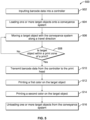
- one or more target objects 106 are loaded onto the conveyance system 104.
- the target objects 106 When loaded onto the conveyance system 104, the target objects 106 may be aligned along or parallel to a printing or travel direction 114 so that the area to be printed is generally perpendicular to the print heads 110.
- target objects 106 may be loaded at a loading zone at predetermined intervals with a loading system, such as an additional conveyance system. Information from an encoder or sensor of the conveyance system 104 may be used to determine when the target object 106 is at the loading zone.
- target objects 106 may be loaded at the loading zone manually by operators.
- the print head 110 prints a first color onto the target object 106.
- the controller 108 sends a control signal to direct the first set of nozzles 202 of the print head 110 to apply the base or background layer of ink 302 (e.g. white ink or ink of another color) onto the target object 106.
- the controller 108 sends a control signal to the first set of nozzles 202 of the print head 110 to apply the first color 402 of the interdigitated pattern (e.g. white ink or ink of another color) onto the target object 106.
- the print head 110 prints a second color onto the target object 106.
- the controller 108 sends a control signal to direct the second set of nozzles 204 of the print head 110, or a second print head, to apply the upper or foreground layer of ink 304 (e.g. black ink or ink of another color) on top of the base layer of ink 302, thereby forming the machine-readable data representation 112.
- This type of data representation 112 can be referred to as a multi-layer data representation 112.
- the target object 106 is unloaded from the conveyance system 104.
- the target object 106 may be unloaded at an unloading zone with an unloading system, such as an additional conveyance system.
- Information from an encoder or sensor of the conveyance system 104 may be used to determine whether the target object 106 is at the unloading zone.
- target objects 106 may be manually unloaded at by operators.
- the print heads 110 are stationary with the target objects 106 moving through the print zone 116 by the conveyance system 104 in the travel direction 114.
- the target objects 106 may remain stationary while the print heads 110 are moved along a travel or printing direction 606.
- both the print heads 110 and the target objects 106 can concurrently move during printing of the representation 112 on at least one of the target objects 106.
- the print heads 110 and the target objects 106 can move in the same direction at the same or different speeds, can move in opposite directions, or can move in transverse directions.
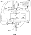
- FIG 6 is a schematic diagram of a printing system 600 in accordance with another embodiment.
- the printing system 600 includes a printing assembly 602 may be used in place of the printing assembly 102 shown in Figures 1 through 2 in the printing system 600.
- One difference between the printing assemblies 102 and 602 is that each print head 110 is connected to a conveyance system 604 that can move the print heads 110 in a printing direction 606 through the print zone 116 while the target objects 106 remain stationary or substantially stationary.
- the printing system 600 includes curing devices 608 disposed after the print heads 110 relative to the travel direction 114 that assist in curing the inks deposited onto the target objects 106 by the print heads 110.
- the conveyance system 604 is operatively connected to the controller 108 to move the print heads 110 along the printing direction 606 through the print zone 116 associated with the print heads 110 for printing the machine-readable data representation 112 according to a set of parameters associated with a grading standard.
- the machine-readable data representation 112 may be formed from one or more different colors in a multilayer or interdigitated pattern that have a symbol contrast of at least 40% and/or meet at least a Grace C of a GS-1 2d bar code verification standard.
- the machine-readable data representation 112 may be formed according the parameters of any machine readable symbology, including, but not limited to Universal Product Code (UPC), Interleaved Two of Five (ITF), European Article Number (EAN), and other standards.
- the parameters associated with the grading standard may include, but are not limited to symbol contrast, reflectance, edge contrast, modulation, defects, decodability, bar width deviation, and the like.
- the controller 108 may control when the conveyance system 604 moves the print heads 110, which direction(s) the print heads 110 are moved, how fast the print heads 110 are moved, and the like.
- the conveyance system 604 can include one or more belts, tracks, rails, or the like, that move or convey the print heads 110. While a conveyor belt system is shown in the illustrated embodiment, it may be noted that other systems, including linear guide systems and/or magnet driven systems, may be utilized as a conveyance system in other embodiments.
- the conveyance system 604 can also include one or more encoders, sensors, and the like to determine positional information regarding the print heads 110 as they move along the printing direction, such as position, velocity, orientation, and the like.
- the conveyance system 604 can index each target object 106 to and from the print zone 116. For example, one or more target objects 106 are loaded onto the conveyance system 604. In one aspect, the target objects 106 can be separately placed onto the conveyance system 604 in a loading area. For target objects 106 to be printed on next by the printing heads 110, the conveyance system 604 moves or indexes the target objects 106 in a travel direction 114 to the print zone 116. The target objects 106 are aligned with the print heads 110 of the printing assembly 102 along a travel direction 114.
- the conveyance system 604 may incrementally move the objects 106 on the conveyance system 604 in the travel direction 114 so that the target object 106 that was just printed on is no longer aligned with the print zone 116, but the next target object 106 that has not yet been printed upon is aligned with the print zone 116.
- the printing system 100 can repeat this process for additional target objects 106.
- a printing system includes one or more print heads configured to print different colors onto a target object to form a machine-readable data representation on the target object having a symbol contrast of at least 40%.
- the printing system also includes a controller configured to direct the one or more print heads to print the different colors by directing the one or more print heads to one or more of print the machine-readable data representation as a multi-layer data representation by printing a base layer of a first color of the different colors on the target object and printing an upper layer of a different, second color of the different colors on top of the base layer of the first color, or print the machine-readable data representation as an interdigitated data representation by printing the different colors onto the target object so that none of the different colors is printed on top of another color of the different colors.
- the controller is configured to direct the one or more print heads to print the machine-readable data representation on an area of the target object that is formed from corrugated cardboard.
- the controller is configured to direct the one or more print heads to print the machine-readable data representation on an area of the target object that is formed from a non-porous material.
- the one or more print heads are configured to print the machine-readable data representation on the target object with a symbol contrast of at least a Grade C of a GS-1 2D bar code verification standard.
- a printing method includes aligning a target object along or parallel to a travel direction, moving one or more of a printing assembly or the target object along the travel direction, and printing a machine-readable data representation with two or more inks of different colors onto the target object to form the machine-readable data representation on the one or more target objects as having a symbol contrast of at least 40%.
- printing the machine-readable data representation includes printing separate layers of ink in an interdigitated pattern to form an interdigitated machine-readable data representation.
- printing the machine-readable data representation includes printing a base layer of a first color of the different colors of the inks on the target object and printing an upper layer of a different, second color of the different colors of the inks on the base layer of the first color.
- the machine-readable data representation includes a bar code with a symbol contrast of at least 40%.
- the method also includes applying a clear coating layer to the target object prior to printing the machine-readable data representation on the clear coating layer.
- a printing system includes a printing assembly having one or more print heads configured to print two or more inks onto a target object having a porous surface, and a conveyance system configured to move one or more of the printing assembly or the target object in a travel direction.
- the conveyance system is configured to move the one or more of the printing assembly or the target object in the travel direction so that the one or more print heads complete printing of a machine-readable data representation formed by the two or more inks onto the target object during one or more of a single pass of the printing assembly over the target object or a single pass of the target object below the printing assembly.
- the machine-readable data representation is printed to have a symbol contrast of at least 40%.
- the one or more print heads are configured to print layers of the inks in an interdigitated pattern to form the machine-readable data representation as an interdigitated machine-readable data representation.
- the one or more print heads are configured to print plural different layers of the inks on top of each other on the target object to form the machine-readable data representation as a multi-layer machine-readable data representation.
- the machine-readable data representation that is printed is a bar code with a symbol contrast of at least 40%.
- the printing assembly includes one or more curing devices configured to cure the inks during the one or more of the single pass of the printing assembly over the target object or the single pass of the target object below the printing assembly.
- the one or more print heads are configured to print the machine-readable data representation on the target object with a symbol contrast of at least a Grade C of a GS-1 2D bar code verification standard.
- the machine-readable data representation that is printed is a QR code.
- the machine-readable data representation that is printed is a two-dimensional bar code with a symbol contrast of at least 40%.
- a processor or a processing unit includes processing circuitry configured to perform one or more tasks, functions, or steps, such as those described herein.
- the processor may be a logic-based device that performs operations based on instructions stored on a tangible and non-transitory computer readable medium, such as memory.
- a "processor,” as used herein, is not intended to necessarily be limited to a single processor or single logic-based device.
- the processor may include a single processor (e.g., having one or more cores), multiple discrete processors, one or more application specific integrated circuits (ASICs), and/or one or more field programmable gate arrays (FPGAs).
- the processor is an off-the-shelf device that is appropriately programmed or instructed to perform operations, such as the algorithms described herein.
- the processor may also be a hard-wired device (e.g., electronic circuitry) that performs the operations based on hard-wired logic that is configured to perform the algorithms described herein.
- the processor may include one or more ASICs and/or FPGAs.
- the processor may include or may be associated with a tangible and non-transitory memory having stored thereon instructions configured to direct the processor to perform the algorithms described herein.
- operations performed by the processor may be sufficiently complex that the operations may not be performed by a human being within a reasonable time period.
- the processor may be configured to receive signals from the various sub-systems and devices of the system or user inputs from the user.
- the processor may be configured to perform the methods described herein.
- a structure, limitation, or element that is “configured to” perform a task or operation is particularly structurally formed, constructed, or adapted in a manner corresponding to the task or operation.
- an object that is merely capable of being modified to perform the task or operation is not “configured to” perform the task or operation as used herein.
- the use of "configured to” as used herein denotes structural adaptations or characteristics, and denotes structural requirements of any structure, limitation, or element that is described as being “configured to” perform the task or operation.
- a processing unit, processor, or computer that is "configured to" perform a task or operation may be understood as being particularly structured to perform the task or operation (e.g., having one or more programs or instructions stored thereon or used in conjunction therewith tailored or intended to perform the task or operation, and/or having an arrangement of processing circuitry tailored or intended to perform the task or operation).
- a general-purpose computer which may become “configured to” perform the task or operation if appropriately programmed) is not “configured to” perform a task or operation unless or until specifically programmed or structurally modified to perform the task or operation.
Landscapes
- Physics & Mathematics (AREA)
- General Physics & Mathematics (AREA)
- Engineering & Computer Science (AREA)
- Theoretical Computer Science (AREA)
- Ink Jet (AREA)
- Ink Jet Recording Methods And Recording Media Thereof (AREA)
- Printing Methods (AREA)
- Application Of Or Painting With Fluid Materials (AREA)
Applications Claiming Priority (4)
| Application Number | Priority Date | Filing Date | Title |
|---|---|---|---|
| US201762536508P | 2017-07-25 | 2017-07-25 | |
| US16/043,327 US10882309B2 (en) | 2017-07-25 | 2018-07-24 | Printing system and method |
| PCT/US2018/043604 WO2019023299A1 (en) | 2017-07-25 | 2018-07-25 | PRINTING SYSTEM AND METHOD |
| EP18752946.6A EP3658383B1 (de) | 2017-07-25 | 2018-07-25 | Drucksystem und -verfahren |
Related Parent Applications (2)
| Application Number | Title | Priority Date | Filing Date |
|---|---|---|---|
| EP18752946.6A Division EP3658383B1 (de) | 2017-07-25 | 2018-07-25 | Drucksystem und -verfahren |
| EP18752946.6A Division-Into EP3658383B1 (de) | 2017-07-25 | 2018-07-25 | Drucksystem und -verfahren |
Publications (2)
| Publication Number | Publication Date |
|---|---|
| EP4223545A1 true EP4223545A1 (de) | 2023-08-09 |
| EP4223545B1 EP4223545B1 (de) | 2025-06-11 |
Family
ID=65041351
Family Applications (2)
| Application Number | Title | Priority Date | Filing Date |
|---|---|---|---|
| EP23170449.5A Active EP4223545B1 (de) | 2017-07-25 | 2018-07-25 | Drucksystem und -verfahren |
| EP18752946.6A Active EP3658383B1 (de) | 2017-07-25 | 2018-07-25 | Drucksystem und -verfahren |
Family Applications After (1)
| Application Number | Title | Priority Date | Filing Date |
|---|---|---|---|
| EP18752946.6A Active EP3658383B1 (de) | 2017-07-25 | 2018-07-25 | Drucksystem und -verfahren |
Country Status (5)
| Country | Link |
|---|---|
| US (3) | US10882309B2 (de) |
| EP (2) | EP4223545B1 (de) |
| ES (2) | ES3039492T3 (de) |
| MX (1) | MX2022003620A (de) |
| WO (1) | WO2019023299A1 (de) |
Families Citing this family (2)
| Publication number | Priority date | Publication date | Assignee | Title |
|---|---|---|---|---|
| US10882309B2 (en) * | 2017-07-25 | 2021-01-05 | Illinois Tool Works Inc. | Printing system and method |
| US20220072872A1 (en) * | 2020-09-09 | 2022-03-10 | Xerox Corporation | Printer configuration for late stage marking on corrugated stock |
Citations (4)
| Publication number | Priority date | Publication date | Assignee | Title |
|---|---|---|---|---|
| JP2006248029A (ja) * | 2005-03-10 | 2006-09-21 | Canon Finetech Inc | インクジェット記録装置 |
| JP2006321065A (ja) * | 2005-05-17 | 2006-11-30 | Canon Finetech Inc | インクジェット記録装置、該装置用記録媒体およびインクジェット記録方法 |
| JP2007136735A (ja) * | 2005-11-15 | 2007-06-07 | Canon Finetech Inc | インクジェット記録方法、記録物および記録装置 |
| US20160185127A1 (en) * | 2013-09-12 | 2016-06-30 | Agfa Graphics Nv | Large cuboid shaped object inkjet printing |
Family Cites Families (59)
| Publication number | Priority date | Publication date | Assignee | Title |
|---|---|---|---|---|
| US6002416A (en) | 1993-01-22 | 1999-12-14 | Gerber Scientific Products, Inc. | Method and apparatus for thermal transfer color printing |
| US5542971A (en) | 1994-12-01 | 1996-08-06 | Pitney Bowes | Bar codes using luminescent invisible inks |
| US6102537A (en) | 1995-02-13 | 2000-08-15 | Canon Kabushiki Kaisha | Method and apparatus for ink-jet printing |
| US6432528B1 (en) | 1998-12-09 | 2002-08-13 | 3M Innovative Properties Company | Variably printed tape and system for printing and applying tape onto surfaces |
| JP3880258B2 (ja) | 1999-09-30 | 2007-02-14 | キヤノン株式会社 | プリント装置及びプリント方法 |
| US6584894B1 (en) | 2000-03-06 | 2003-07-01 | Nibco, Inc. | Method and apparatus for marking items of varied shapes |
| DE10117035B4 (de) | 2000-04-27 | 2006-08-17 | Hewlett-Packard Development Co., L.P., Houston | Drucktechnik zum Verbergen von Bandgrenzen-Banderscheinungen |
| JP2002037224A (ja) * | 2000-07-21 | 2002-02-06 | Fuji Photo Film Co Ltd | 梱包体の製造方法、梱包体、及び印刷装置 |
| US6476840B1 (en) | 2000-08-02 | 2002-11-05 | Sony Chemical Corporation Of America | Radiation-curable thermal printing ink and ink ribbons and methods of making, using and printing using the same |
| US20020164453A1 (en) | 2000-10-23 | 2002-11-07 | Babcock Bruce W. | Printable composite paperboard for packaging |
| GB2370249A (en) * | 2000-11-04 | 2002-06-26 | Zipher | Method of printing an image onto a low contrast substrate |
| JP2003001804A (ja) | 2001-06-20 | 2003-01-08 | Toshiba Tec Corp | インクジェットプリンタ、ノズル数算出方法、インクジェット印字方法および印字媒体 |
| US7311395B2 (en) * | 2001-09-07 | 2007-12-25 | Hewlett-Packard Development Company, L.P. | Optimized ink jet printing of barcodes |
| US7463376B2 (en) | 2002-01-30 | 2008-12-09 | Hewlett-Packard Development Company, L.P. | Print finishing method and apparatus |
| JP2003341144A (ja) * | 2002-05-27 | 2003-12-03 | Riso Kagaku Corp | バーコード印刷装置 |
| US7181969B2 (en) | 2002-07-16 | 2007-02-27 | Sonix, Inc. | Ultrasonic test chamber for tray production system and the like |
| DE102005021185A1 (de) | 2004-05-03 | 2005-11-24 | Man Roland Druckmaschinen Ag | Verfahren und Vorrichtung zur Applikation von Deckweiß und Effektschichten auf einen Bedruckstoff |
| DE602005010597D1 (de) | 2004-08-30 | 2008-12-04 | Konica Minolta Med & Graphic | Bildaufzeichnungsverfahren |
| US7274883B2 (en) | 2005-03-22 | 2007-09-25 | Marvell International Technology Ltd. | Hybrid printer and related system and method |
| EP1838085A3 (de) | 2006-03-20 | 2008-07-02 | Brother Kogyo Kabushiki Kaisha | Druckdatenerzeugungsvorrichtung und Ansteuerungsverfahren dafür |
| US7946668B2 (en) | 2006-10-13 | 2011-05-24 | Fujifilm Dimatix, Inc. | Printing on a rotating surface |
| US20080156863A1 (en) | 2006-12-29 | 2008-07-03 | Weyerhaeuser Co. | Systems and methods for improving the readability of printed bar code symbols and the like |
| US20080304891A1 (en) | 2007-06-07 | 2008-12-11 | Canon Finetech Inc. | Barcode generation system, barcode generation program, and printing device |
| ES2400839T3 (es) | 2007-10-24 | 2013-04-12 | Agfa Graphics Nv | Tinta de inyección blanca mejorada para la estabilidad de la dispersión |
| JP5207719B2 (ja) | 2007-12-05 | 2013-06-12 | 株式会社トプコン | カラーコード付き標識、カラーコード抽出手段及び三次元計測システム |
| US8199367B2 (en) | 2007-12-21 | 2012-06-12 | Seiko Epson Corporation | Printing control device, printing system and printing control program |
| EP2352651B1 (de) * | 2008-12-03 | 2017-03-29 | Videojet Technologies, Inc. | Tintenstrahldrucksystem und verfahren |
| US8235516B2 (en) | 2008-12-18 | 2012-08-07 | Pitney Bowes Inc. | Print enhancement of pixels to improve readability |
| US20100155494A1 (en) | 2008-12-18 | 2010-06-24 | Pitney Bowes Inc. | Print containment of pixels to improve readability |
| JP5493895B2 (ja) | 2009-04-03 | 2014-05-14 | セイコーエプソン株式会社 | 白色を含む複数色のインクを用いた印刷 |
| JP5885117B2 (ja) | 2010-03-23 | 2016-03-15 | セイコーエプソン株式会社 | 記録方法 |
| US9174480B2 (en) | 2010-09-30 | 2015-11-03 | Peter D. Battisti | Inkjet-printable flexography substrate, method of making, and method of using |
| CN102649344A (zh) | 2011-02-25 | 2012-08-29 | 深圳劲嘉彩印集团股份有限公司 | 条形码印刷设备及其方法 |
| KR20120104943A (ko) | 2011-03-14 | 2012-09-24 | 세이코 엡슨 가부시키가이샤 | 인쇄층 형성 처리 장치, 인쇄층 형성 처리 방법, 인쇄층 형성 처리 방법을 실행시키기 위한 프로그램이 기록된 컴퓨터 판독가능 기록 매체 및 인쇄 시스템 |
| JP5747585B2 (ja) | 2011-03-16 | 2015-07-15 | 東洋インキScホールディングス株式会社 | インキ組成物およびそれを用いた硬化物 |
| WO2013016860A1 (zh) | 2011-08-01 | 2013-02-07 | 北京美科艺数码科技发展有限公司 | 喷墨打印装置及其打印方法 |
| US8702195B2 (en) | 2011-09-02 | 2014-04-22 | Hewlett-Packard Development Company, L.P. | Determining misalignment of a printhead in a printer |
| JP5858708B2 (ja) | 2011-09-27 | 2016-02-10 | 理想科学工業株式会社 | バーコード印刷制御装置 |
| CN202600742U (zh) | 2012-04-09 | 2012-12-12 | 东莞智源彩印有限公司 | 一种条形码 |
| US9851928B2 (en) | 2012-04-12 | 2017-12-26 | Hp Indigo B.V. | Printing with target color data |
| PL2826824T3 (pl) | 2012-06-06 | 2017-02-28 | Agfa Graphics Nv | Utwardzalne radiacyjnie tusze do druku natryskowego i sposoby przemysłowego druku natryskowego |
| WO2014082671A1 (en) * | 2012-11-29 | 2014-06-05 | Hewlett-Packard Development Company, L.P. | Operation of printing systems |
| CN102995487B (zh) | 2012-12-21 | 2015-09-23 | 常德金鹏印务有限公司 | 仿金卡纸的制备方法、条形码的印制方法以及包装品的加工方法 |
| US20140255645A1 (en) | 2013-03-07 | 2014-09-11 | Foxbox Originals Llc | Direct texture print production |
| US20140313257A1 (en) * | 2013-03-15 | 2014-10-23 | Illinois Tool Works Inc. | System and method for single pass printing |
| WO2014156130A1 (ja) | 2013-03-29 | 2014-10-02 | セイコーエプソン株式会社 | 印刷制御装置、印刷装置、データ処理方法、及び、印刷制御装置の設定方法 |
| EP2818327B1 (de) | 2013-06-24 | 2016-03-02 | Agfa Graphics Nv | Drucken mit weißer Tintenstrahltinte |
| WO2015042846A1 (zh) | 2013-09-27 | 2015-04-02 | 北京美科艺数码科技发展有限公司 | 喷墨打印方法和喷墨打印装置 |
| CN103725104B (zh) | 2013-12-20 | 2015-03-04 | 靳职雄 | 一种条形码的制造方法 |
| JP5728750B1 (ja) | 2014-02-20 | 2015-06-03 | 東洋インキScホールディングス株式会社 | 活性エネルギー線硬化型平版オフセットインキおよびその印刷物 |
| US9833948B2 (en) | 2014-05-08 | 2017-12-05 | Adobe Systems Incorporated | 3D printing of colored models on multi-head printers |
| CN105109228A (zh) | 2015-08-20 | 2015-12-02 | 江苏昌昇集团股份有限公司 | 一种利用印刷机印刷条形码的方法 |
| US10685317B2 (en) * | 2015-09-22 | 2020-06-16 | United States Postal Service | Trackable postage |
| CN108349266A (zh) * | 2016-01-28 | 2018-07-31 | 惠普发展公司有限责任合伙企业 | 关于纸箱衬里的瓦楞板轧制机控制信息 |
| DE102016103318A1 (de) * | 2016-02-25 | 2017-08-31 | Océ Holding B.V. | Verfahren zur Überprüfung eines Druckkopfes zur Aufbringung eines Fixiermittels bei einem Tintendruckgerät |
| US10385239B2 (en) * | 2016-04-04 | 2019-08-20 | Intertape Polymer Corp. | Carton sealing tape with a plurality of security features |
| MX2018013632A (es) | 2016-05-31 | 2019-07-18 | Nike Innovate Cv | Metodo para imprimir un objeto contorneado mediante el uso de capas de color y estructurales. |
| CN106364192A (zh) | 2016-08-30 | 2017-02-01 | 江苏大亚印务有限公司 | 一种条形码印刷方法 |
| US10882309B2 (en) * | 2017-07-25 | 2021-01-05 | Illinois Tool Works Inc. | Printing system and method |
-
2018
- 2018-07-24 US US16/043,327 patent/US10882309B2/en active Active
- 2018-07-25 WO PCT/US2018/043604 patent/WO2019023299A1/en not_active Ceased
- 2018-07-25 ES ES23170449T patent/ES3039492T3/es active Active
- 2018-07-25 EP EP23170449.5A patent/EP4223545B1/de active Active
- 2018-07-25 EP EP18752946.6A patent/EP3658383B1/de active Active
- 2018-07-25 ES ES18752946T patent/ES2963053T3/es active Active
-
2020
- 2020-01-15 MX MX2022003620A patent/MX2022003620A/es unknown
- 2020-12-03 US US17/111,280 patent/US11331905B2/en active Active
-
2022
- 2022-03-21 US US17/699,700 patent/US12076982B2/en active Active
Patent Citations (4)
| Publication number | Priority date | Publication date | Assignee | Title |
|---|---|---|---|---|
| JP2006248029A (ja) * | 2005-03-10 | 2006-09-21 | Canon Finetech Inc | インクジェット記録装置 |
| JP2006321065A (ja) * | 2005-05-17 | 2006-11-30 | Canon Finetech Inc | インクジェット記録装置、該装置用記録媒体およびインクジェット記録方法 |
| JP2007136735A (ja) * | 2005-11-15 | 2007-06-07 | Canon Finetech Inc | インクジェット記録方法、記録物および記録装置 |
| US20160185127A1 (en) * | 2013-09-12 | 2016-06-30 | Agfa Graphics Nv | Large cuboid shaped object inkjet printing |
Also Published As
| Publication number | Publication date |
|---|---|
| US11331905B2 (en) | 2022-05-17 |
| EP4223545B1 (de) | 2025-06-11 |
| US12076982B2 (en) | 2024-09-03 |
| US20220203675A1 (en) | 2022-06-30 |
| WO2019023299A1 (en) | 2019-01-31 |
| ES3039492T3 (en) | 2025-10-21 |
| EP3658383A1 (de) | 2020-06-03 |
| ES2963053T3 (es) | 2024-03-25 |
| US20210086505A1 (en) | 2021-03-25 |
| MX2022003620A (es) | 2022-06-14 |
| US10882309B2 (en) | 2021-01-05 |
| EP3658383B1 (de) | 2023-09-06 |
| US20190030884A1 (en) | 2019-01-31 |
Similar Documents
| Publication | Publication Date | Title |
|---|---|---|
| US12076982B2 (en) | Printing system and method | |
| US10507677B2 (en) | Dual card transport in a card processing system | |
| CN101274543B (zh) | 印刷三维物品的设备和方法 | |
| EP2098355B2 (de) | Blasmaschine und Blasverfahren mit einer Druckeinrichtung | |
| US10706239B1 (en) | Integrated label printer and barcode reader, and related systems and methods | |
| WO2012005733A1 (en) | Rfid antenna and 2d barcode | |
| US20100236712A1 (en) | Fully automatic rfid labeler | |
| EP3964361B1 (de) | Verfahren und system zum drucken | |
| JP7169983B2 (ja) | パッケージング材料用の印刷システム | |
| CN101128733A (zh) | 印刷系统和方法 | |
| EP4190563B1 (de) | Verfahren zur herstellung einer markierung auf einem verpackungsmaterial | |
| US20140313257A1 (en) | System and method for single pass printing | |
| CN113165399A (zh) | 在柔性材料上打印的系统和方法 | |
| US11919294B2 (en) | System and method for decorating suitcases and luggage items | |
| US20170210120A1 (en) | Systems and methods for monitoring overprint orientation | |
| CN122034552A (zh) | 叠印图形处理方法、工业印刷控制方法和系统 | |
| CN108712985A (zh) | 对来自卷筒的有型廓的环绕式标签进行处理 | |
| KR20250032245A (ko) | 적층형 입체라벨의 제조장치, 그 제조방법 및 이를 이용한 입체라벨 | |
| HK1233584A1 (en) | Machine for printing simultaneously on two parallel surfaces | |
| KR20110083568A (ko) | 인몰드용 인쇄필름 제조방법 | |
| JP2007026124A (ja) | ワーク識別方法 |
Legal Events
| Date | Code | Title | Description |
|---|---|---|---|
| PUAI | Public reference made under article 153(3) epc to a published international application that has entered the european phase |
Free format text: ORIGINAL CODE: 0009012 |
|
| STAA | Information on the status of an ep patent application or granted ep patent |
Free format text: STATUS: THE APPLICATION HAS BEEN PUBLISHED |
|
| AC | Divisional application: reference to earlier application |
Ref document number: 3658383 Country of ref document: EP Kind code of ref document: P |
|
| AK | Designated contracting states |
Kind code of ref document: A1 Designated state(s): AL AT BE BG CH CY CZ DE DK EE ES FI FR GB GR HR HU IE IS IT LI LT LU LV MC MK MT NL NO PL PT RO RS SE SI SK SM TR |
|
| STAA | Information on the status of an ep patent application or granted ep patent |
Free format text: STATUS: REQUEST FOR EXAMINATION WAS MADE |
|
| 17P | Request for examination filed |
Effective date: 20240206 |
|
| RBV | Designated contracting states (corrected) |
Designated state(s): AL AT BE BG CH CY CZ DE DK EE ES FI FR GB GR HR HU IE IS IT LI LT LU LV MC MK MT NL NO PL PT RO RS SE SI SK SM TR |
|
| STAA | Information on the status of an ep patent application or granted ep patent |
Free format text: STATUS: EXAMINATION IS IN PROGRESS |
|
| 17Q | First examination report despatched |
Effective date: 20240429 |
|
| GRAP | Despatch of communication of intention to grant a patent |
Free format text: ORIGINAL CODE: EPIDOSNIGR1 |
|
| STAA | Information on the status of an ep patent application or granted ep patent |
Free format text: STATUS: GRANT OF PATENT IS INTENDED |
|
| INTG | Intention to grant announced |
Effective date: 20250130 |
|
| P01 | Opt-out of the competence of the unified patent court (upc) registered |
Free format text: CASE NUMBER: APP_9473/2025 Effective date: 20250225 |
|
| GRAS | Grant fee paid |
Free format text: ORIGINAL CODE: EPIDOSNIGR3 |
|
| GRAA | (expected) grant |
Free format text: ORIGINAL CODE: 0009210 |
|
| STAA | Information on the status of an ep patent application or granted ep patent |
Free format text: STATUS: THE PATENT HAS BEEN GRANTED |
|
| AC | Divisional application: reference to earlier application |
Ref document number: 3658383 Country of ref document: EP Kind code of ref document: P |
|
| AK | Designated contracting states |
Kind code of ref document: B1 Designated state(s): AL AT BE BG CH CY CZ DE DK EE ES FI FR GB GR HR HU IE IS IT LI LT LU LV MC MK MT NL NO PL PT RO RS SE SI SK SM TR |
|
| REG | Reference to a national code |
Ref country code: GB Ref legal event code: FG4D |
|
| REG | Reference to a national code |
Ref country code: CH Ref legal event code: EP |
|
| REG | Reference to a national code |
Ref country code: DE Ref legal event code: R096 Ref document number: 602018082612 Country of ref document: DE |
|
| REG | Reference to a national code |
Ref country code: IE Ref legal event code: FG4D |
|
| PG25 | Lapsed in a contracting state [announced via postgrant information from national office to epo] |
Ref country code: FI Free format text: LAPSE BECAUSE OF FAILURE TO SUBMIT A TRANSLATION OF THE DESCRIPTION OR TO PAY THE FEE WITHIN THE PRESCRIBED TIME-LIMIT Effective date: 20250611 |
|
| PGFP | Annual fee paid to national office [announced via postgrant information from national office to epo] |
Ref country code: ES Payment date: 20250901 Year of fee payment: 8 |
|
| PGFP | Annual fee paid to national office [announced via postgrant information from national office to epo] |
Ref country code: DE Payment date: 20250929 Year of fee payment: 8 |
|
| REG | Reference to a national code |
Ref country code: LT Ref legal event code: MG9D |
|
| PG25 | Lapsed in a contracting state [announced via postgrant information from national office to epo] |
Ref country code: GR Free format text: LAPSE BECAUSE OF FAILURE TO SUBMIT A TRANSLATION OF THE DESCRIPTION OR TO PAY THE FEE WITHIN THE PRESCRIBED TIME-LIMIT Effective date: 20250912 Ref country code: NO Free format text: LAPSE BECAUSE OF FAILURE TO SUBMIT A TRANSLATION OF THE DESCRIPTION OR TO PAY THE FEE WITHIN THE PRESCRIBED TIME-LIMIT Effective date: 20250911 |
|
| PGFP | Annual fee paid to national office [announced via postgrant information from national office to epo] |
Ref country code: IT Payment date: 20250919 Year of fee payment: 8 |
|
| REG | Reference to a national code |
Ref country code: NL Ref legal event code: MP Effective date: 20250611 |
|
| PG25 | Lapsed in a contracting state [announced via postgrant information from national office to epo] |
Ref country code: BG Free format text: LAPSE BECAUSE OF FAILURE TO SUBMIT A TRANSLATION OF THE DESCRIPTION OR TO PAY THE FEE WITHIN THE PRESCRIBED TIME-LIMIT Effective date: 20250611 |
|
| PGFP | Annual fee paid to national office [announced via postgrant information from national office to epo] |
Ref country code: GB Payment date: 20250929 Year of fee payment: 8 |
|
| PG25 | Lapsed in a contracting state [announced via postgrant information from national office to epo] |
Ref country code: HR Free format text: LAPSE BECAUSE OF FAILURE TO SUBMIT A TRANSLATION OF THE DESCRIPTION OR TO PAY THE FEE WITHIN THE PRESCRIBED TIME-LIMIT Effective date: 20250611 |
|
| PGFP | Annual fee paid to national office [announced via postgrant information from national office to epo] |
Ref country code: FR Payment date: 20250925 Year of fee payment: 8 |
|
| REG | Reference to a national code |
Ref country code: ES Ref legal event code: FG2A Ref document number: 3039492 Country of ref document: ES Kind code of ref document: T3 Effective date: 20251021 |
|
| PG25 | Lapsed in a contracting state [announced via postgrant information from national office to epo] |
Ref country code: RS Free format text: LAPSE BECAUSE OF FAILURE TO SUBMIT A TRANSLATION OF THE DESCRIPTION OR TO PAY THE FEE WITHIN THE PRESCRIBED TIME-LIMIT Effective date: 20250911 |
|
| PG25 | Lapsed in a contracting state [announced via postgrant information from national office to epo] |
Ref country code: LV Free format text: LAPSE BECAUSE OF FAILURE TO SUBMIT A TRANSLATION OF THE DESCRIPTION OR TO PAY THE FEE WITHIN THE PRESCRIBED TIME-LIMIT Effective date: 20250611 |
|
| PG25 | Lapsed in a contracting state [announced via postgrant information from national office to epo] |
Ref country code: NL Free format text: LAPSE BECAUSE OF FAILURE TO SUBMIT A TRANSLATION OF THE DESCRIPTION OR TO PAY THE FEE WITHIN THE PRESCRIBED TIME-LIMIT Effective date: 20250611 |
|
| PG25 | Lapsed in a contracting state [announced via postgrant information from national office to epo] |
Ref country code: PT Free format text: LAPSE BECAUSE OF FAILURE TO SUBMIT A TRANSLATION OF THE DESCRIPTION OR TO PAY THE FEE WITHIN THE PRESCRIBED TIME-LIMIT Effective date: 20251013 |
|
| REG | Reference to a national code |
Ref country code: AT Ref legal event code: MK05 Ref document number: 1802065 Country of ref document: AT Kind code of ref document: T Effective date: 20250611 |
|
| PG25 | Lapsed in a contracting state [announced via postgrant information from national office to epo] |
Ref country code: IS Free format text: LAPSE BECAUSE OF FAILURE TO SUBMIT A TRANSLATION OF THE DESCRIPTION OR TO PAY THE FEE WITHIN THE PRESCRIBED TIME-LIMIT Effective date: 20251011 |
|
| PG25 | Lapsed in a contracting state [announced via postgrant information from national office to epo] |
Ref country code: SM Free format text: LAPSE BECAUSE OF FAILURE TO SUBMIT A TRANSLATION OF THE DESCRIPTION OR TO PAY THE FEE WITHIN THE PRESCRIBED TIME-LIMIT Effective date: 20250611 Ref country code: AT Free format text: LAPSE BECAUSE OF FAILURE TO SUBMIT A TRANSLATION OF THE DESCRIPTION OR TO PAY THE FEE WITHIN THE PRESCRIBED TIME-LIMIT Effective date: 20250611 |
|
| PG25 | Lapsed in a contracting state [announced via postgrant information from national office to epo] |
Ref country code: CZ Free format text: LAPSE BECAUSE OF FAILURE TO SUBMIT A TRANSLATION OF THE DESCRIPTION OR TO PAY THE FEE WITHIN THE PRESCRIBED TIME-LIMIT Effective date: 20250611 |
|
| PG25 | Lapsed in a contracting state [announced via postgrant information from national office to epo] |
Ref country code: PL Free format text: LAPSE BECAUSE OF FAILURE TO SUBMIT A TRANSLATION OF THE DESCRIPTION OR TO PAY THE FEE WITHIN THE PRESCRIBED TIME-LIMIT Effective date: 20250611 |
|
| PG25 | Lapsed in a contracting state [announced via postgrant information from national office to epo] |
Ref country code: EE Free format text: LAPSE BECAUSE OF FAILURE TO SUBMIT A TRANSLATION OF THE DESCRIPTION OR TO PAY THE FEE WITHIN THE PRESCRIBED TIME-LIMIT Effective date: 20250611 |
|
| PG25 | Lapsed in a contracting state [announced via postgrant information from national office to epo] |
Ref country code: SK Free format text: LAPSE BECAUSE OF FAILURE TO SUBMIT A TRANSLATION OF THE DESCRIPTION OR TO PAY THE FEE WITHIN THE PRESCRIBED TIME-LIMIT Effective date: 20250611 |
|
| REG | Reference to a national code |
Ref country code: CH Ref legal event code: H13 Free format text: ST27 STATUS EVENT CODE: U-0-0-H10-H13 (AS PROVIDED BY THE NATIONAL OFFICE) Effective date: 20260224 |
|
| PG25 | Lapsed in a contracting state [announced via postgrant information from national office to epo] |
Ref country code: RO Free format text: LAPSE BECAUSE OF FAILURE TO SUBMIT A TRANSLATION OF THE DESCRIPTION OR TO PAY THE FEE WITHIN THE PRESCRIBED TIME-LIMIT Effective date: 20250611 |
|
| REG | Reference to a national code |
Ref country code: DE Ref legal event code: R097 Ref document number: 602018082612 Country of ref document: DE |
|
| PG25 | Lapsed in a contracting state [announced via postgrant information from national office to epo] |
Ref country code: LU Free format text: LAPSE BECAUSE OF NON-PAYMENT OF DUE FEES Effective date: 20250725 |
|
| REG | Reference to a national code |
Ref country code: BE Ref legal event code: MM Effective date: 20250731 |
|
| PG25 | Lapsed in a contracting state [announced via postgrant information from national office to epo] |
Ref country code: MC Free format text: LAPSE BECAUSE OF FAILURE TO SUBMIT A TRANSLATION OF THE DESCRIPTION OR TO PAY THE FEE WITHIN THE PRESCRIBED TIME-LIMIT Effective date: 20250611 |
|
| PG25 | Lapsed in a contracting state [announced via postgrant information from national office to epo] |
Ref country code: DK Free format text: LAPSE BECAUSE OF FAILURE TO SUBMIT A TRANSLATION OF THE DESCRIPTION OR TO PAY THE FEE WITHIN THE PRESCRIBED TIME-LIMIT Effective date: 20250611 |
|
| PG25 | Lapsed in a contracting state [announced via postgrant information from national office to epo] |
Ref country code: BE Free format text: LAPSE BECAUSE OF NON-PAYMENT OF DUE FEES Effective date: 20250731 |
|
| PLBE | No opposition filed within time limit |
Free format text: ORIGINAL CODE: 0009261 |
|
| STAA | Information on the status of an ep patent application or granted ep patent |
Free format text: STATUS: NO OPPOSITION FILED WITHIN TIME LIMIT |
|
| PG25 | Lapsed in a contracting state [announced via postgrant information from national office to epo] |
Ref country code: CH Free format text: LAPSE BECAUSE OF NON-PAYMENT OF DUE FEES Effective date: 20250731 |
|
| REG | Reference to a national code |
Ref country code: CH Ref legal event code: L10 Free format text: ST27 STATUS EVENT CODE: U-0-0-L10-L00 (AS PROVIDED BY THE NATIONAL OFFICE) Effective date: 20260423 |