EP4223389B1 - Filterelement mit griff - Google Patents
Filterelement mit griff Download PDFInfo
- Publication number
- EP4223389B1 EP4223389B1 EP23154612.8A EP23154612A EP4223389B1 EP 4223389 B1 EP4223389 B1 EP 4223389B1 EP 23154612 A EP23154612 A EP 23154612A EP 4223389 B1 EP4223389 B1 EP 4223389B1
- Authority
- EP
- European Patent Office
- Prior art keywords
- filtering
- handle portion
- filtering element
- base portion
- end flap
- Prior art date
- Legal status (The legal status is an assumption and is not a legal conclusion. Google has not performed a legal analysis and makes no representation as to the accuracy of the status listed.)
- Active
Links
Images


Classifications
-
- B—PERFORMING OPERATIONS; TRANSPORTING
- B01—PHYSICAL OR CHEMICAL PROCESSES OR APPARATUS IN GENERAL
- B01D—SEPARATION
- B01D46/00—Filters or filtering processes specially modified for separating dispersed particles from gases or vapours
- B01D46/10—Particle separators, e.g. dust precipitators, using filter plates, sheets or pads having plane surfaces
-
- B—PERFORMING OPERATIONS; TRANSPORTING
- B01—PHYSICAL OR CHEMICAL PROCESSES OR APPARATUS IN GENERAL
- B01D—SEPARATION
- B01D46/00—Filters or filtering processes specially modified for separating dispersed particles from gases or vapours
- B01D46/42—Auxiliary equipment or operation thereof
- B01D46/4227—Manipulating filters or filter elements, e.g. handles or extracting tools
-
- B—PERFORMING OPERATIONS; TRANSPORTING
- B01—PHYSICAL OR CHEMICAL PROCESSES OR APPARATUS IN GENERAL
- B01D—SEPARATION
- B01D46/00—Filters or filtering processes specially modified for separating dispersed particles from gases or vapours
- B01D46/52—Particle separators, e.g. dust precipitators, using filters embodying folded corrugated or wound sheet material
- B01D46/521—Particle separators, e.g. dust precipitators, using filters embodying folded corrugated or wound sheet material using folded, pleated material
Definitions
- the present invention relates to a filtering element comprising a zigzag-folded filtering web ending at opposite ends thereof with respective end flaps, and opposing side bands joined to the filtering web.
- Filtering elements formed by a zigzag-folded filtering web and made in particular of nonwoven fabric are produced for a wide range of applications.
- such filtering elements are used to filter fresh air for the passenger compartment of motor vehicles or in air conditioning systems for indoor spaces.
- filtering elements of this type are inserted into housings such as frames or boxes.
- Such an air filter comprising gripping members is disclosed in EP 1944072 .
- One object of the present invention is to make available a solution that allows the filtering element to be easily removed from its housing at the end of its life.
- a subject of the invention is a filtering element of the type defined at the outset, further comprising a sheet element made of a plastics material superimposed to one of the end flaps, said sheet element comprising a base portion fixed to the particular end flap and a handle portion connected to the base portion by a film hinge extending along a direction parallel to the folding lines of the filtering web, said handle portion being thereby foldable from an inactive position, in which the handle portion is substantially coplanar with the base portion, to a use position, in which the handle portion is raised relative to the base portion and to the particular end flap.
- the handle portion may thus be lifted manually at the end of the filtering element's life, facilitating the extraction of the filtering element from its housing.
- the sheet element further comprises a fastening portion connected to the base portion by an elastic loop, in such a way that the sheet element is clipped to the particular end flap at an edge thereof.
- a fastening portion connected to the base portion by an elastic loop, in such a way that the sheet element is clipped to the particular end flap at an edge thereof.
- At least one gripping aperture is formed through the handle portion. This makes it easier to grip the handle portion and thus extract the filter from the housing thereof.
- At least one hook projection is formed on the handle portion at the film hinge, said hook projection being configured to bite onto the end flap when the handle portion is in the use position.
- This arrangement ensures, in cooperation with the clip fastening, effective retention of the filtering element as it is removed from its housing.
- the hook projection extends from the handle portion to beyond the film hinge.
- an insert made of elastomeric material is obtained frontally on the base portion.
- this arrangement makes it possible on the one hand to seal the perimeter of the filtering element to the passage of air, and on the other hand to avoid noise between the plastics of the filtering element and the particular housing.
- the insert partially extends into the elastic loop between the base portion and the fastening portion.
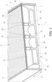
- Fig. 1 and 2 show a filtering element 1 comprising a zigzag-folded filtering web 2.
- the filtering element 1 has a substantially plate-like shape and further comprises two opposing side bands 3 and 4, made of the same material as the filtering web 2 and joined thereto.
- the material of the filtering element may comprise, for example, a nonwoven fabric and may comprise a single layer or several layers coupled together.
- respective reinforcing side bands 5, 6 of plastics material are in turn fixed to the two side bands 3, 4.
- the reinforcing side bands 5, 6 may be absent, or the side bands 3, 4 made of the same material as the filtering web 2 may be absent.
- the filtering web 2 comprises two respective end flaps, which delimit the filtering web 2 in the longitudinal direction. Only one of these end flaps is visible in the figures and is indicated by 7.
- "longitudinal direction” means the direction orthogonal to the folding lines 2a of the filtering web 2.
- the end flap 7 ends with a relevant end edge 7a, extending approximately parallel to the folding lines 2a.
- the end flap 7 is connected to the rest of the filtering web 2 at one of the folding lines 2a.
- Fig. 1 also shows schematically, with a dotted line, a filter housing 11 suitable for receiving the filtering element 1.
- the filter housing 11 may be, for example, a frame or a box, and is configured to allow a flow of fluid, e.g., air, to pass through the filtering element 1 according to a direction approximately orthogonal to a plane in which the folding lines 2a lie.
- the filter housing 11 defines an inlet 11a that allows the insertion or the extraction of the filtering element 1 according to the direction of the arrow A shown in Fig. 1 , parallel to the "longitudinal direction" defined above.
- the inlet 11a is suitable for being closed by a cover (not shown) which, when the filtering element 1 is inserted into the filter housing 11, is positioned opposite to the end flap 7.
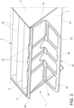
- the filtering element 1 further comprises a sheet element 20 of plastics material superimposed to the end flap 7.
- the sheet element 20 comprising a base portion 21 fixed to the end flap 7 and a handle portion 22 connected to the base portion 21 by a film hinge 23.
- the film hinge 23 extends along a direction parallel to the folding lines 2a of the filtering web 2.
- the handle portion 22 of the sheet element 20 is foldable from an inactive position (shown in Fig. 1 and 4 ), in which the handle portion 22 is substantially coplanar with the base portion 21, to a use position (shown in Fig. 2 , 3 and 5 ), in which the handle portion 22 is raised relative to the base portion 21, and to the particular end flap 7.
- the handle portion 22 rests or is lying on the end flap, while in the use position the handle portion 22 is substantially upright, forming a certain angle with the base portion 21, in particular of approximately 90°.
- the sheet element 20 further comprises a fastening portion 24 connected to the base portion by an elastic loop 25, in such a way that the sheet element 20 is clipped to the end flap 7 at the free edge 7a of the flap.
- the base portion 21 and the fastening portion 24 press on opposite faces of the end flap by exerting an elastic retaining force that holds the sheet element 20 on the end flap 7.
- the elastic loop 25 of the sheet element 20 is arranged astride the free edge 7a of the end flap 7. In this manner, the sheet element 20 may be easily press-fitted onto the end flap 7 without requiring the use of additional devices, such as, for example, adhesives.
- the filtering web 2 and especially the end flap 7 are shown as transparent so that the fastening portion 24 of the sheet element 20 is visible.
- At least one gripping aperture 26 is formed through the handle portion 22.
- At least one hook projection 27 is made on the handle portion 22 at the film hinge 23.
- the hook projection 27 is configured to bite onto the end flap 7 when the handle portion 22 of the sheet element 20 is in the use position. To this end, the hook projection 27 extends from the handle portion 22 to beyond the film hinge.
- the hook projection 27 thus interferes with a surface of the end flap 7, penetrating into the material of which it is made. This exerts an effective biting action on the end flap 7 that prevents the sheet element 20 from inadvertently slipping off the flap when the handle portion 22 is pulled to extract the filtering element 1 out of the filter housing 11.
- An insert 28 made of elastomeric material is obtained frontally on the base portion 21 of the sheet element 20.
- the insert 28 extends for a length substantially equal to the width of the filtering element 1.
- the insert 28 further extends partially into the elastic loop 21 between the base portion 21 and the fastening portion 24 of the sheet element 20.
- this cover compresses the insert 28, which acts as a gasket to seal the perimeter of the filtering element 1 against the filter housing 11.
- the insert 28 prevents noise between the plastics of the filtering element and the particular housing thereof.
Landscapes
- Chemical & Material Sciences (AREA)
- Chemical Kinetics & Catalysis (AREA)
- Filtering Of Dispersed Particles In Gases (AREA)
- Food-Manufacturing Devices (AREA)
Claims (8)
- Filterelement (1), aufweisendeine zickzackförmig gefaltete Filterschicht (2), die an ihren entgegengesetzten Enden mit jeweiligen Endlaschen (7) abschließt, undeinander gegenüberliegende Seitenstreifen (3, 5; 4, 6), die mit der Filterschicht (2) verbunden sind,dadurch gekennzeichnet, dass es weiter ein Folienelement (20) aus Kunststoffmaterial aufweist, welches auf eine der Endlaschen (7) aufgebracht ist, wobei das Folienelement einen Basisabschnitt (21), welcher an die jeweilige Endlasche (7) angebracht ist, und ein Griffteil (22) aufweist, welches durch ein Filmscharnier (23), das sich entlang einer parallel zu den Faltlinien (2a) der Filterschicht (2) verlaufenden Richtung erstreckt, mit dem Basisabschnitt (21) verbunden ist, wobei das Griffteil dadurch von einer inaktiven Stellung, in welcher das Griffteil (22) im Wesentlichen koplanar mit dem Basisabschnitt (21) ist, in eine Gebrauchsstellung umklappbar ist, in welcher das Griffteil (22) bezüglich dem Basisabschnitt (21) und der jeweiligen Endlasche (7) angehoben wird.
- Filterelement nach Anspruch 1, wobei das Folienelement (20) weiter einen Befestigungsabschnitt (24) aufweist, der durch eine elastische Schlaufe (25) derart mit dem Basisabschnitt (21) verbunden ist, dass das Folienelement (20) an die jeweilige Endlasche (7) an einen ihrer Ränder (7a) angehängt ist.
- Filterelement nach Anspruch 2, wobei der Rand (7a) die jeweilige Endlasche (7) auf einer ihrer Seiten, die einer der Faltlinien (2a) der Filterschicht (2) entgegengesetzt ist, begrenzt.
- Filterelement nach einem der vorangehenden Ansprüche, wobei mindestens eine Greiföffnung (26) durch das Griffteil (22) hindurch ausgebildet ist.
- Filterelement nach einem der vorangehenden Ansprüche, wobei mindestens ein Hakenvorsprung (27) am Griffteil (22) an dem Filmscharnier (23) ausgebildet ist, wobei der Hakenvorsprung dazu ausgelegt ist, in die jeweilige Endlasche (7) einzugreifen, wenn das Griffteil (22) in der Gebrauchsstellung ist.
- Filterelement nach Anspruch 5, wobei der Hakenvorsprung (27) sich von dem Griffteil (22) über das Filmscharnier (23) hinaus erstreckt.
- Filterelement nach einem der vorangehenden Ansprüche, wobei ein Einsatz (28) aus elastomerem Material frontal an dem Basisabschnitt (21) ausgebildet ist.
- Filterelement nach Anspruch 7 in Kombination mit Anspruch 2, wobei der Einsatz (28) sich teilweise in die elastische Schlaufe (25) zwischen dem Basisabschnitt (21) und dem Befestigungsabschnitt (24) hinein erstreckt.
Priority Applications (1)
| Application Number | Priority Date | Filing Date | Title |
|---|---|---|---|
| MA64077A MA64077B1 (fr) | 2022-02-04 | 2023-02-02 | Élément filtrant à poignée |
Applications Claiming Priority (1)
| Application Number | Priority Date | Filing Date | Title |
|---|---|---|---|
| IT102022000001976A IT202200001976A1 (it) | 2022-02-04 | 2022-02-04 | Elemento filtrante con maniglia di estrazione |
Publications (3)
| Publication Number | Publication Date |
|---|---|
| EP4223389A1 EP4223389A1 (de) | 2023-08-09 |
| EP4223389C0 EP4223389C0 (de) | 2024-08-14 |
| EP4223389B1 true EP4223389B1 (de) | 2024-08-14 |
Family
ID=81308432
Family Applications (1)
| Application Number | Title | Priority Date | Filing Date |
|---|---|---|---|
| EP23154612.8A Active EP4223389B1 (de) | 2022-02-04 | 2023-02-02 | Filterelement mit griff |
Country Status (4)
| Country | Link |
|---|---|
| EP (1) | EP4223389B1 (de) |
| ES (1) | ES2991729T3 (de) |
| IT (1) | IT202200001976A1 (de) |
| MA (1) | MA64077B1 (de) |
Family Cites Families (6)
| Publication number | Priority date | Publication date | Assignee | Title |
|---|---|---|---|---|
| DE4117550C2 (de) * | 1991-05-29 | 1997-06-12 | Knecht Filterwerke Gmbh | Plattenfilter aus zick-zack-förmig gefaltetem Bahnenmaterial |
| JP2002166113A (ja) * | 2000-11-29 | 2002-06-11 | Akamatsu Denki Seisakusho:Kk | 集塵用フィルター |
| FR2911288B1 (fr) * | 2007-01-12 | 2009-03-13 | Valeo Materiaux De Friction Sa | Procede de fabrication d'un dispositif de filtration d'air et dispositif fabrique grace a un tel procede |
| DE202008006299U1 (de) * | 2008-05-07 | 2009-09-10 | Mann+Hummel Gmbh | Filterelement |
| CA2943387C (en) * | 2014-03-21 | 2022-09-06 | 3M Innovative Properties Company | Refillable air filter assembly |
| CN212790189U (zh) * | 2020-03-19 | 2021-03-26 | 苏州康冠净化科技有限公司 | 一种过滤芯 |
-
2022
- 2022-02-04 IT IT102022000001976A patent/IT202200001976A1/it unknown
-
2023
- 2023-02-02 ES ES23154612T patent/ES2991729T3/es active Active
- 2023-02-02 EP EP23154612.8A patent/EP4223389B1/de active Active
- 2023-02-02 MA MA64077A patent/MA64077B1/fr unknown
Also Published As
| Publication number | Publication date |
|---|---|
| MA64077B1 (fr) | 2024-10-31 |
| IT202200001976A1 (it) | 2023-08-04 |
| EP4223389C0 (de) | 2024-08-14 |
| ES2991729T3 (es) | 2024-12-04 |
| EP4223389A1 (de) | 2023-08-09 |
Similar Documents
| Publication | Publication Date | Title |
|---|---|---|
| US8075658B2 (en) | Filter element | |
| US5554205A (en) | Air filter for the interior of a motor vehicle | |
| US20010022069A1 (en) | Filter cartridge | |
| CN106039879B (zh) | 带有连接板的过滤器元件和过滤器系统 | |
| US20080047240A1 (en) | Flexible Filter Element | |
| CN102284203B (zh) | 具有盖部和自承式的过滤元件的系统 | |
| US8182570B2 (en) | Compact air filter element | |
| US1125535A (en) | Envelop. | |
| JP5602521B2 (ja) | エアフィルタ挿入体 | |
| EP4223389B1 (de) | Filterelement mit griff | |
| JP3766812B2 (ja) | フィルタ装置 | |
| CN106999827B (zh) | 平坦的过滤元件及过滤装置 | |
| EP2319602B1 (de) | Filterbaugruppe einer Fahrzeugheizungs- oder Klimaanlage, Filtereinheit hierfür und Verfahren zur Herstellung der Filterbaugruppe | |
| JP3693617B2 (ja) | フィルタ | |
| US11148090B2 (en) | Pocket filter assembly | |
| US20060277725A1 (en) | Clip for clipping sheets together | |
| JPH09844A (ja) | 排気口用フィルタの取付け具および排気口へのフィルタの取付け方法 | |
| JP3745787B2 (ja) | フィルタ | |
| JP4474331B2 (ja) | フィルターカバー取付方法及びフィルター装置 | |
| EP1518715A1 (de) | Heftklammer, insbesondere verwendbar in Kraftfahrzeugen | |
| US12208662B2 (en) | Housing for a heating, air-conditioning and/or ventilation device for a motor vehicle | |
| KR200421848Y1 (ko) | 공조용 공기필터 | |
| JP6262622B2 (ja) | フィルタ枠およびエアフィルタ | |
| JP3054842U (ja) | 鎧付き布製折り畳み式ジャバラ。 | |
| JPH10286421A (ja) | 空気清浄器用フィルタ構造 |
Legal Events
| Date | Code | Title | Description |
|---|---|---|---|
| PUAI | Public reference made under article 153(3) epc to a published international application that has entered the european phase |
Free format text: ORIGINAL CODE: 0009012 |
|
| STAA | Information on the status of an ep patent application or granted ep patent |
Free format text: STATUS: THE APPLICATION HAS BEEN PUBLISHED |
|
| AK | Designated contracting states |
Kind code of ref document: A1 Designated state(s): AL AT BE BG CH CY CZ DE DK EE ES FI FR GB GR HR HU IE IS IT LI LT LU LV MC ME MK MT NL NO PL PT RO RS SE SI SK SM TR |
|
| STAA | Information on the status of an ep patent application or granted ep patent |
Free format text: STATUS: REQUEST FOR EXAMINATION WAS MADE |
|
| 17P | Request for examination filed |
Effective date: 20240108 |
|
| RAV | Requested validation state of the european patent: fee paid |
Extension state: MA Effective date: 20240108 |
|
| RBV | Designated contracting states (corrected) |
Designated state(s): AL AT BE BG CH CY CZ DE DK EE ES FI FR GB GR HR HU IE IS IT LI LT LU LV MC ME MK MT NL NO PL PT RO RS SE SI SK SM TR |
|
| GRAP | Despatch of communication of intention to grant a patent |
Free format text: ORIGINAL CODE: EPIDOSNIGR1 |
|
| STAA | Information on the status of an ep patent application or granted ep patent |
Free format text: STATUS: GRANT OF PATENT IS INTENDED |
|
| INTG | Intention to grant announced |
Effective date: 20240325 |
|
| GRAS | Grant fee paid |
Free format text: ORIGINAL CODE: EPIDOSNIGR3 |
|
| GRAA | (expected) grant |
Free format text: ORIGINAL CODE: 0009210 |
|
| STAA | Information on the status of an ep patent application or granted ep patent |
Free format text: STATUS: THE PATENT HAS BEEN GRANTED |
|
| AK | Designated contracting states |
Kind code of ref document: B1 Designated state(s): AL AT BE BG CH CY CZ DE DK EE ES FI FR GB GR HR HU IE IS IT LI LT LU LV MC ME MK MT NL NO PL PT RO RS SE SI SK SM TR |
|
| REG | Reference to a national code |
Ref country code: GB Ref legal event code: FG4D |
|
| REG | Reference to a national code |
Ref country code: CH Ref legal event code: EP |
|
| REG | Reference to a national code |
Ref country code: DE Ref legal event code: R096 Ref document number: 602023000361 Country of ref document: DE |
|
| REG | Reference to a national code |
Ref country code: IE Ref legal event code: FG4D |
|
| U01 | Request for unitary effect filed |
Effective date: 20240904 |
|
| U07 | Unitary effect registered |
Designated state(s): AT BE BG DE DK EE FI FR IT LT LU LV MT NL PT RO SE SI Effective date: 20240923 |
|
| REG | Reference to a national code |
Ref country code: MA Ref legal event code: VAGR Ref document number: 64077 Country of ref document: MA Kind code of ref document: B1 |
|
| REG | Reference to a national code |
Ref country code: ES Ref legal event code: FG2A Ref document number: 2991729 Country of ref document: ES Kind code of ref document: T3 Effective date: 20241204 |
|
| PG25 | Lapsed in a contracting state [announced via postgrant information from national office to epo] |
Ref country code: NO Free format text: LAPSE BECAUSE OF FAILURE TO SUBMIT A TRANSLATION OF THE DESCRIPTION OR TO PAY THE FEE WITHIN THE PRESCRIBED TIME-LIMIT Effective date: 20241114 |
|
| PG25 | Lapsed in a contracting state [announced via postgrant information from national office to epo] |
Ref country code: GR Free format text: LAPSE BECAUSE OF FAILURE TO SUBMIT A TRANSLATION OF THE DESCRIPTION OR TO PAY THE FEE WITHIN THE PRESCRIBED TIME-LIMIT Effective date: 20241115 Ref country code: PL Free format text: LAPSE BECAUSE OF FAILURE TO SUBMIT A TRANSLATION OF THE DESCRIPTION OR TO PAY THE FEE WITHIN THE PRESCRIBED TIME-LIMIT Effective date: 20240814 |
|
| PG25 | Lapsed in a contracting state [announced via postgrant information from national office to epo] |
Ref country code: IS Free format text: LAPSE BECAUSE OF FAILURE TO SUBMIT A TRANSLATION OF THE DESCRIPTION OR TO PAY THE FEE WITHIN THE PRESCRIBED TIME-LIMIT Effective date: 20241214 |
|
| PG25 | Lapsed in a contracting state [announced via postgrant information from national office to epo] |
Ref country code: HR Free format text: LAPSE BECAUSE OF FAILURE TO SUBMIT A TRANSLATION OF THE DESCRIPTION OR TO PAY THE FEE WITHIN THE PRESCRIBED TIME-LIMIT Effective date: 20240814 |
|
| PG25 | Lapsed in a contracting state [announced via postgrant information from national office to epo] |
Ref country code: RS Free format text: LAPSE BECAUSE OF FAILURE TO SUBMIT A TRANSLATION OF THE DESCRIPTION OR TO PAY THE FEE WITHIN THE PRESCRIBED TIME-LIMIT Effective date: 20241114 |
|
| PG25 | Lapsed in a contracting state [announced via postgrant information from national office to epo] |
Ref country code: RS Free format text: LAPSE BECAUSE OF FAILURE TO SUBMIT A TRANSLATION OF THE DESCRIPTION OR TO PAY THE FEE WITHIN THE PRESCRIBED TIME-LIMIT Effective date: 20241114 Ref country code: PL Free format text: LAPSE BECAUSE OF FAILURE TO SUBMIT A TRANSLATION OF THE DESCRIPTION OR TO PAY THE FEE WITHIN THE PRESCRIBED TIME-LIMIT Effective date: 20240814 Ref country code: NO Free format text: LAPSE BECAUSE OF FAILURE TO SUBMIT A TRANSLATION OF THE DESCRIPTION OR TO PAY THE FEE WITHIN THE PRESCRIBED TIME-LIMIT Effective date: 20241114 Ref country code: IS Free format text: LAPSE BECAUSE OF FAILURE TO SUBMIT A TRANSLATION OF THE DESCRIPTION OR TO PAY THE FEE WITHIN THE PRESCRIBED TIME-LIMIT Effective date: 20241214 Ref country code: HR Free format text: LAPSE BECAUSE OF FAILURE TO SUBMIT A TRANSLATION OF THE DESCRIPTION OR TO PAY THE FEE WITHIN THE PRESCRIBED TIME-LIMIT Effective date: 20240814 Ref country code: GR Free format text: LAPSE BECAUSE OF FAILURE TO SUBMIT A TRANSLATION OF THE DESCRIPTION OR TO PAY THE FEE WITHIN THE PRESCRIBED TIME-LIMIT Effective date: 20241115 |
|
| U20 | Renewal fee for the european patent with unitary effect paid |
Year of fee payment: 3 Effective date: 20250122 |
|
| PG25 | Lapsed in a contracting state [announced via postgrant information from national office to epo] |
Ref country code: SM Free format text: LAPSE BECAUSE OF FAILURE TO SUBMIT A TRANSLATION OF THE DESCRIPTION OR TO PAY THE FEE WITHIN THE PRESCRIBED TIME-LIMIT Effective date: 20240814 |
|
| PGFP | Annual fee paid to national office [announced via postgrant information from national office to epo] |
Ref country code: ES Payment date: 20250303 Year of fee payment: 3 |
|
| PG25 | Lapsed in a contracting state [announced via postgrant information from national office to epo] |
Ref country code: CZ Free format text: LAPSE BECAUSE OF FAILURE TO SUBMIT A TRANSLATION OF THE DESCRIPTION OR TO PAY THE FEE WITHIN THE PRESCRIBED TIME-LIMIT Effective date: 20240814 |
|
| PG25 | Lapsed in a contracting state [announced via postgrant information from national office to epo] |
Ref country code: SK Free format text: LAPSE BECAUSE OF FAILURE TO SUBMIT A TRANSLATION OF THE DESCRIPTION OR TO PAY THE FEE WITHIN THE PRESCRIBED TIME-LIMIT Effective date: 20240814 |
|
| PGFP | Annual fee paid to national office [announced via postgrant information from national office to epo] |
Ref country code: TR Payment date: 20250203 Year of fee payment: 3 |
|
| PLBE | No opposition filed within time limit |
Free format text: ORIGINAL CODE: 0009261 |
|
| STAA | Information on the status of an ep patent application or granted ep patent |
Free format text: STATUS: NO OPPOSITION FILED WITHIN TIME LIMIT |
|
| 26N | No opposition filed |
Effective date: 20250515 |
|
| PG25 | Lapsed in a contracting state [announced via postgrant information from national office to epo] |
Ref country code: MC Free format text: LAPSE BECAUSE OF FAILURE TO SUBMIT A TRANSLATION OF THE DESCRIPTION OR TO PAY THE FEE WITHIN THE PRESCRIBED TIME-LIMIT Effective date: 20240814 |
|
| VSFP | Annual fee paid to validation state [announced via postgrant information from national office to epo] |
Ref country code: MA Payment date: 20250203 Year of fee payment: 3 |
|
| PG25 | Lapsed in a contracting state [announced via postgrant information from national office to epo] |
Ref country code: IE Free format text: LAPSE BECAUSE OF NON-PAYMENT OF DUE FEES Effective date: 20250202 |
|
| U20 | Renewal fee for the european patent with unitary effect paid |
Year of fee payment: 4 Effective date: 20251230 |