EP4220876A1 - Device for storing, transporting and installing electrical wires and cables - Google Patents
Device for storing, transporting and installing electrical wires and cables Download PDFInfo
- Publication number
- EP4220876A1 EP4220876A1 EP23153287.0A EP23153287A EP4220876A1 EP 4220876 A1 EP4220876 A1 EP 4220876A1 EP 23153287 A EP23153287 A EP 23153287A EP 4220876 A1 EP4220876 A1 EP 4220876A1
- Authority
- EP
- European Patent Office
- Prior art keywords
- cable
- cables
- wire
- reel
- transporting
- Prior art date
- Legal status (The legal status is an assumption and is not a legal conclusion. Google has not performed a legal analysis and makes no representation as to the accuracy of the status listed.)
- Pending
Links
- 239000002655 kraft paper Substances 0.000 claims description 4
- 238000009434 installation Methods 0.000 description 6
- 238000004806 packaging method and process Methods 0.000 description 4
- OKTJSMMVPCPJKN-UHFFFAOYSA-N Carbon Chemical compound [C] OKTJSMMVPCPJKN-UHFFFAOYSA-N 0.000 description 1
- 229910052799 carbon Inorganic materials 0.000 description 1
- 238000010276 construction Methods 0.000 description 1
- 230000007613 environmental effect Effects 0.000 description 1
- 230000004048 modification Effects 0.000 description 1
- 238000012986 modification Methods 0.000 description 1
- 239000004033 plastic Substances 0.000 description 1
- 239000002985 plastic film Substances 0.000 description 1
- 229920006255 plastic film Polymers 0.000 description 1
- 238000005096 rolling process Methods 0.000 description 1
- 239000002699 waste material Substances 0.000 description 1
Images

Classifications
-
- H—ELECTRICITY
- H02—GENERATION; CONVERSION OR DISTRIBUTION OF ELECTRIC POWER
- H02G—INSTALLATION OF ELECTRIC CABLES OR LINES, OR OF COMBINED OPTICAL AND ELECTRIC CABLES OR LINES
- H02G1/00—Methods or apparatus specially adapted for installing, maintaining, repairing or dismantling electric cables or lines
- H02G1/06—Methods or apparatus specially adapted for installing, maintaining, repairing or dismantling electric cables or lines for laying cables, e.g. laying apparatus on vehicle
-
- B—PERFORMING OPERATIONS; TRANSPORTING
- B65—CONVEYING; PACKING; STORING; HANDLING THIN OR FILAMENTARY MATERIAL
- B65D—CONTAINERS FOR STORAGE OR TRANSPORT OF ARTICLES OR MATERIALS, e.g. BAGS, BARRELS, BOTTLES, BOXES, CANS, CARTONS, CRATES, DRUMS, JARS, TANKS, HOPPERS, FORWARDING CONTAINERS; ACCESSORIES, CLOSURES, OR FITTINGS THEREFOR; PACKAGING ELEMENTS; PACKAGES
- B65D85/00—Containers, packaging elements or packages, specially adapted for particular articles or materials
- B65D85/02—Containers, packaging elements or packages, specially adapted for particular articles or materials for annular articles
- B65D85/04—Containers, packaging elements or packages, specially adapted for particular articles or materials for annular articles for coils of wire, rope or hose
-
- B—PERFORMING OPERATIONS; TRANSPORTING
- B65—CONVEYING; PACKING; STORING; HANDLING THIN OR FILAMENTARY MATERIAL
- B65H—HANDLING THIN OR FILAMENTARY MATERIAL, e.g. SHEETS, WEBS, CABLES
- B65H49/00—Unwinding or paying-out filamentary material; Supporting, storing or transporting packages from which filamentary material is to be withdrawn or paid-out
- B65H49/18—Methods or apparatus in which packages rotate
- B65H49/20—Package-supporting devices
- B65H49/205—Hand-held or portable dispensers
-
- B—PERFORMING OPERATIONS; TRANSPORTING
- B65—CONVEYING; PACKING; STORING; HANDLING THIN OR FILAMENTARY MATERIAL
- B65H—HANDLING THIN OR FILAMENTARY MATERIAL, e.g. SHEETS, WEBS, CABLES
- B65H75/00—Storing webs, tapes, or filamentary material, e.g. on reels
- B65H75/02—Cores, formers, supports, or holders for coiled, wound, or folded material, e.g. reels, spindles, bobbins, cop tubes, cans, mandrels or chucks
- B65H75/18—Constructional details
- B65H75/28—Arrangements for positively securing ends of material
-
- B—PERFORMING OPERATIONS; TRANSPORTING
- B65—CONVEYING; PACKING; STORING; HANDLING THIN OR FILAMENTARY MATERIAL
- B65H—HANDLING THIN OR FILAMENTARY MATERIAL, e.g. SHEETS, WEBS, CABLES
- B65H2701/00—Handled material; Storage means
- B65H2701/30—Handled filamentary material
- B65H2701/34—Handled filamentary material electric cords or electric power cables
Definitions
- the present invention relates to a device for storing, transporting and installing electric wires and cables.
- the invention belongs to the field of equipment for electric wires and electric cables in various sectors, such as construction or industry.
- the installer typically already has other objects on hand, such as a toolbox, a ladder, etc. and therefore has little availability for the transport of the reel.
- this type of packaging generally produces kinking of the wire or cable because it is unwound from the inside of the reel.
- the object of the present invention is to remedy the aforementioned drawbacks of the prior art.
- the present invention covers, in a compact and very easy to use form, all of the functionalities of storage, transport and installation of electrical wires or cables. It facilitates the transport of a reel, by rolling the box on the ground, allows several reels to be transported simultaneously, on the rotating shaft, saves time during installation, reduces the risks associated with handling , a limitation of the scrap rate and has a reduced environmental footprint thanks to the sustainable nature of the transport and storage solution and the facilitated collection of waste.
- the base of the U-shaped handle has an adjustable length.
- the branches of the U-shaped handle have an adjustable length.
- the installer can thus adjust the height of the handle, for example according to its size, for better transport ergonomics.
- the housing has on its circumference at least one opening adapted to the passage of the electric wire or cable.
- the reel of electric wire or cable is surrounded on its circumference by a strip of kraft paper having at least one opening adapted to the passage of the electric wire or cable.
- the reel is packaged without plastic and therefore has a reduced carbon footprint.
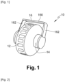
- a device 10 for storing, transporting and installing electrical wires or cables in accordance with the present invention comprises one or more casings 12 in the form of a wheel.
- the device 10 can roll on the ground and is therefore easily transportable.
- the device 10 comprises a single housing 12 and in the embodiment of the figure 2 , the device 10 comprises three housings 12, these numbers of housings being in no way limiting examples, the number of housings possibly being arbitrary.
- the housing 12 is traversed by a rotation shaft 14 and can rotate independently of it.
- the box 12 contains a coil 30 on which is wound an electrical wire or cable 22 (visible on the picture 3 ).
- the coil 30 is rotatable around the rotation shaft 14.
- the casing 12 can for example be formed of two half-shells assembled together by any suitable means. It may be either two torus-shaped half-shells, or two half-shells assembled along a radial plane.
- the coil 30 may be surrounded on its circumference by a strip of kraft paper 32, which constitutes its packaging and on which any indication relating to the identification of the electrical wire or cable 22 (reference, color, section, length, etc.).
- the strip of kraft paper 32 has one or more openings 34 suitable for the passage of the electric wire or cable 22.
- the opening 34 is diamond-shaped.
- the device 10 further comprises a handle 16 for gripping and transporting the device 10.
- the handle 16 is U-shaped, the U having a base 160 and two branches 162.
- each of the legs 162 is attached to an opposite end of the rotation shaft 14.
- the end of each branch 162 can for example be provided with a disc-shaped cap, of the same diameter as the rotation shaft 14 and fitting onto the end of the rotation shaft 14 facing of the considered branch 162.
- the base 160 of the U-shaped handle 16 can have an adjustable length.
- the base 160 of the handle 16 can be formed from the at least partial superposition of a first part in one piece with one of the branches 162 and orthogonal thereto and of a second part of one piece with the other arm 162 and orthogonal thereto, the first part having a series of openings and the second part having a series of protuberances adapted to be clipped and released from the openings by simple traction on the two arms 162.
- One can thus adjust the length of the base 160 of the handle 16 depending on the number of boxes 12 to be placed on the rotation shaft 14.
- the length of the branches 162 can also be adjustable to allow good ergonomics regardless of the size of the installer.
- the branches 162 are for example made up of several nested segments, which gives them a telescopic character.
- the housing 12 may have on its circumference one or more openings 20 suitable for the passage of the electric wire or cable 22, thus making it possible to unwind the latter outside the coil 30 and acting both as a grommet and thread guide.
- the boxes have on their circumference a series of regularly distributed openings 20, which avoids having to roll the boxes 12 until an opening 20 is found.
- a tool can be provided. in the form of a ruler, where the correspondence between the section, the mass of the section and the number of meters remaining on the reel 30 can be read.
Abstract
Ce dispositif (10) de stockage, transport et installation de fils ou câbles électriques comporte au moins un boîtier (12) en forme de roue, traversé par un arbre de rotation (14) et contenant une bobine de fil ou câble électrique mobile en rotation autour de l'arbre de rotation (14) ; et une poignée (16) en U comportant une base (160) et deux branches (162), chacune des deux branches (162) étant fixée à une extrémité opposée de l'arbre de rotation (14).This device (10) for storing, transporting and installing electric wires or cables comprises at least one casing (12) in the form of a wheel, through which passes a rotating shaft (14) and containing a reel of wire or electric cable movable in rotation. around the rotating shaft (14); and a U-shaped handle (16) having a base (160) and two legs (162), each of the two legs (162) being attached to an opposite end of the rotation shaft (14).
Description
La présente invention se rapporte à un dispositif de stockage, transport et installation de fils et câbles électriques.The present invention relates to a device for storing, transporting and installing electric wires and cables.
L'invention appartient au domaine des équipements pour fils électriques et câbles électriques dans des secteurs variés, tels le bâtiment ou l'industrie.The invention belongs to the field of equipment for electric wires and electric cables in various sectors, such as construction or industry.
Pour l'installateur, les fils ou câbles électriques se présentent souvent sous forme d'une bobine emballée dans un film plastique. Cela présente divers inconvénients tout au long du transport, de l'installation et de l'utilisation de ces fils ou câbles.For the installer, electrical wires or cables often come in the form of a reel wrapped in a plastic film. This presents various disadvantages throughout the transportation, installation and use of these wires or cables.
En effet, typiquement, lors du transport de la bobine du camion vers le site d'installation, l'installateur a généralement déjà en main d'autres objets tels qu'une boîte à outils, une échelle, etc. et n'a donc que peu de disponibilité pour le transport de la bobine.Indeed, typically, when transporting the coil from the truck to the installation site, the installer generally already has other objects on hand, such as a toolbox, a ladder, etc. and therefore has little availability for the transport of the reel.
Puis au moment de l'installation, il est souvent difficile de dérouler le fil ou câble, car la bobine a tendance à se déplacer sur le sol.Then at the time of installation, it is often difficult to unwind the wire or cable, because the reel tends to move on the ground.
En outre, ce type d'emballage produit généralement un entortillement du fil ou câble car celui-ci est déroulé à partir de l'intérieur de la bobine.In addition, this type of packaging generally produces kinking of the wire or cable because it is unwound from the inside of the reel.
Par ailleurs, si l'installateur a besoin d'installer simultanément deux, voire trois fils ou câbles, il rencontre une difficulté supplémentaire étant donné que ces deux, voire trois bobines sont emballées séparément.Furthermore, if the installer needs to install two or even three wires or cables simultaneously, he encounters an additional difficulty since these two or even three coils are packaged separately.
De plus, une fois l'installation terminée, il reste souvent du fil ou câble dans les emballages. Il n'est pas aisé de contenir ce restant de fil ou câble à l'intérieur de l'emballage ouvert, ni de le transporter.In addition, once the installation is complete, there is often wire or cable left in the packaging. It is not easy to contain this remaining wire or cable inside the open packaging, nor to transport it.
La présente invention a pour but de remédier aux inconvénients précités de l'art antérieur.The object of the present invention is to remedy the aforementioned drawbacks of the prior art.
Dans ce but, la présente invention propose un dispositif de stockage, transport et installation de fils ou câbles électriques, remarquable en ce qu'il comporte :
- au moins un boîtier en forme de roue, traversé par un arbre de rotation et
- contenant une bobine de fil ou câble électrique mobile en rotation autour de l'arbre de rotation ; et
- une poignée en U comportant une base et deux branches, chacune des deux branches étant fixée à une extrémité opposée de l'arbre de rotation.
- at least one casing in the form of a wheel, through which a rotating shaft passes and
- containing a reel of wire or electric cable mobile in rotation around the rotating shaft; And
- a U-shaped handle comprising a base and two legs, each of the two legs being attached to an opposite end of the rotation shaft.
Ainsi, la présente invention couvre, sous une forme compacte et très simple d'utilisation, l'ensemble des fonctionnalités de stockage, de transport et d'installation de fils ou câbles électriques. Elle facilite le transport d'une bobine, par roulage du boîtier sur le sol, permet de transporter plusieurs bobines simultanément, sur l'arbre de rotation, offre un gain de temps lors de l'installation, une réduction des risques liés à la manutention, une limitation du taux de rebut et présente une empreinte environnementale réduite grâce au caractère durable de la solution de transport et de stockage et à la collecte facilitée des déchets.Thus, the present invention covers, in a compact and very easy to use form, all of the functionalities of storage, transport and installation of electrical wires or cables. It facilitates the transport of a reel, by rolling the box on the ground, allows several reels to be transported simultaneously, on the rotating shaft, saves time during installation, reduces the risks associated with handling , a limitation of the scrap rate and has a reduced environmental footprint thanks to the sustainable nature of the transport and storage solution and the facilitated collection of waste.
Dans un mode particulier de réalisation, la base de la poignée en U présente une longueur réglable.In a particular embodiment, the base of the U-shaped handle has an adjustable length.
Cela confère un caractère modulable au dispositif, qui peut être utilisé sans modification, hormis le simple réglage de la base de la poignée, pour transporter soit une seule bobine, soit plusieurs bobines de fil ou câble.This gives a modular character to the device, which can be used without modification, apart from the simple adjustment of the base of the handle, to transport either a single reel or several reels of wire or cable.
Dans un mode particulier de réalisation, les branches de la poignée en U présentent une longueur réglable.In a particular embodiment, the branches of the U-shaped handle have an adjustable length.
L'installateur peut ainsi régler la hauteur de la poignée, par exemple en fonction de sa taille, pour une meilleure ergonomie de transport.The installer can thus adjust the height of the handle, for example according to its size, for better transport ergonomics.
Dans un mode particulier de réalisation, le boîtier présente sur sa circonférence au moins une ouverture adaptée au passage du fil ou câble électrique.In a particular embodiment, the housing has on its circumference at least one opening adapted to the passage of the electric wire or cable.
Cela permet de dérouler facilement le fil ou câble à partir de l'extérieur de la bobine et d'éviter ainsi l'entortillement du fil ou câble.This makes it easy to unwind the wire or cable from the outside of the spool and thus avoid tangling the wire or cable.
Dans un mode particulier de réalisation, la bobine de fil ou câble électrique est entourée sur sa circonférence d'une bande de papier kraft présentant au moins une ouverture adaptée au passage du fil ou câble électrique.In a particular embodiment, the reel of electric wire or cable is surrounded on its circumference by a strip of kraft paper having at least one opening adapted to the passage of the electric wire or cable.
Ainsi, la bobine est emballée sans plastique et présente donc une empreinte carbone réduite.Thus, the reel is packaged without plastic and therefore has a reduced carbon footprint.
D'autres aspects et avantages de l'invention apparaîtront à la lecture de la description détaillée ci-après de modes particuliers de réalisation, donnés à titre d'exemples nullement limitatifs, en référence aux dessins annexés, dans lesquels :
- [
Fig. 1 ] est une représentation schématique d'un dispositif conforme à la présente invention, dans un mode particulier de réalisation où il permet de transporter une seule bobine de fil ou câble électrique ; - [
Fig. 2 ] est une représentation schématique d'un dispositif conforme à la présente invention, dans un mode particulier de réalisation où il permet de transporter simultanément trois bobines de fil ou câble électrique. - [
Fig. 3 ] est une représentation schématique d'une bobine de fil ou câble électrique du type contenu dans un dispositif conforme à la présente invention, dans un mode particulier de réalisation.
- [
Fig. 1 ] is a schematic representation of a device according to the present invention, in a particular embodiment where it allows a single coil of wire or electric cable to be transported; - [
Fig. 2 ] is a schematic representation of a device according to the present invention, in a particular embodiment where it allows three coils of wire or electric cable to be transported simultaneously. - [
Fig. 3 ] is a schematic representation of a reel of electrical wire or cable of the type contained in a device according to the present invention, in a particular embodiment.
Comme le montre la
Le boîtier 12 est traversé par un arbre de rotation 14 et peut tourner indépendamment de celui-ci.The
Le boîtier 12 contient une bobine 30 sur laquelle est enroulé un fil ou un câble 22 électrique (visible sur la
Afin de pouvoir introduire la bobine 30 dans le boîtier 12, le boîtier 12 peut par exemple être formé de deux demi-coques assemblées entre elles par tout moyen approprié. Il peut s'agir, soit de deux demi-coques de forme torique, soit de deux demi-coques assemblées suivant un plan radial.In order to be able to introduce the
Comme le montre la
Afin de pouvoir aisément dérouler le fil ou câble 22 électrique enroulé sur la bobine 30, la bande de papier kraft 32 présente une ou plusieurs ouvertures 34 adaptées au passage du fil ou câble 22 électrique. A titre d'exemple non limitatif, dans le mode particulier de réalisation illustré sur la
Le dispositif 10 comporte en outre une poignée 16 permettant la saisie et le transport du dispositif 10. La poignée 16 est en forme de U, le U présentant une base 160 et deux branches 162.The
Chacune des branches 162 est fixée à une extrémité opposée de l'arbre de rotation 14. A cet effet, comme dans les modes de réalisation des
De façon optionnelle, la base 160 de la poignée 16 en U peut présenter une longueur réglable.Optionally, the
Par exemple, la base 160 de la poignée 16 peut être formée de la superposition au moins partielle d'une première partie d'un seul tenant avec l'une des branches 162 et orthogonale à celle-ci et d'une seconde partie d'un seul tenant avec l'autre branche 162 et orthogonale à celle-ci, la première partie présentant une série d'ouvertures et la seconde partie présentant une série de protubérances adaptées à se clipser et se dégager des ouvertures par simple traction sur les deux branches 162. On peut ainsi régler la longueur de la base 160 de la poignée 16 en fonction du nombre de boîtiers 12 à disposer sur l'arbre de rotation 14.For example, the
De façon optionnelle, la longueur des branches 162 peut également être réglable pour permettre une bonne ergonomie quelle que soit la taille de l'installateur. A cette fin, les branches 162 sont par exemple constituées de plusieurs segments gigognes, ce qui leur confère un caractère télescopique.Optionally, the length of the
Comme le montre la
Dans les modes particuliers de réalisation des
Avantageusement, pour permettre à l'installateur de connaître la longueur restante de fil ou câble 22 électrique sur la bobine 30 sans avoir besoin d'ouvrir le boîtier 12 et quelle que soit la section du fil ou câble 22 électrique, on peut prévoir un outil sous forme d'une règle, où se lit la correspondance entre la section, la masse de la section et le nombre de mètres restant sur la bobine 30.Advantageously, to allow the installer to know the remaining length of electric wire or
Claims (5)
Applications Claiming Priority (1)
| Application Number | Priority Date | Filing Date | Title |
|---|---|---|---|
| FR2200713A FR3132181A1 (en) | 2022-01-27 | 2022-01-27 | DEVICE FOR STORAGE, TRANSPORT AND INSTALLATION OF ELECTRIC WIRES AND CABLES |
Publications (1)
| Publication Number | Publication Date |
|---|---|
| EP4220876A1 true EP4220876A1 (en) | 2023-08-02 |
Family
ID=81325972
Family Applications (1)
| Application Number | Title | Priority Date | Filing Date |
|---|---|---|---|
| EP23153287.0A Pending EP4220876A1 (en) | 2022-01-27 | 2023-01-25 | Device for storing, transporting and installing electrical wires and cables |
Country Status (2)
| Country | Link |
|---|---|
| EP (1) | EP4220876A1 (en) |
| FR (1) | FR3132181A1 (en) |
Citations (5)
| Publication number | Priority date | Publication date | Assignee | Title |
|---|---|---|---|---|
| US1726137A (en) * | 1926-11-17 | 1929-08-27 | Tomas Suarez Y Bernal | Reel for cables and wire |
| US2156267A (en) * | 1936-11-27 | 1939-05-02 | Anaconda Wire & Cable Co | Releasable package |
| US20110048992A1 (en) * | 2009-08-25 | 2011-03-03 | Windy City Wire Cable And Technology Products, Llc | Transporter for box of spooled wire or cable |
| US20120085668A1 (en) * | 2009-05-14 | 2012-04-12 | Rodney Dunlap | Small hand carried barrel shaped case used for the storage and dispensing of spools of electrical wire |
| US11040733B1 (en) * | 2018-05-05 | 2021-06-22 | Encore Wire Corporation | Wire caddy for transporting and dispensing wire or cable |
-
2022
- 2022-01-27 FR FR2200713A patent/FR3132181A1/en active Pending
-
2023
- 2023-01-25 EP EP23153287.0A patent/EP4220876A1/en active Pending
Patent Citations (5)
| Publication number | Priority date | Publication date | Assignee | Title |
|---|---|---|---|---|
| US1726137A (en) * | 1926-11-17 | 1929-08-27 | Tomas Suarez Y Bernal | Reel for cables and wire |
| US2156267A (en) * | 1936-11-27 | 1939-05-02 | Anaconda Wire & Cable Co | Releasable package |
| US20120085668A1 (en) * | 2009-05-14 | 2012-04-12 | Rodney Dunlap | Small hand carried barrel shaped case used for the storage and dispensing of spools of electrical wire |
| US20110048992A1 (en) * | 2009-08-25 | 2011-03-03 | Windy City Wire Cable And Technology Products, Llc | Transporter for box of spooled wire or cable |
| US11040733B1 (en) * | 2018-05-05 | 2021-06-22 | Encore Wire Corporation | Wire caddy for transporting and dispensing wire or cable |
Also Published As
| Publication number | Publication date |
|---|---|
| FR3132181A1 (en) | 2023-07-28 |
Similar Documents
| Publication | Publication Date | Title |
|---|---|---|
| EP1224719B1 (en) | Device for guiding at least a flexible elongated element such as a cable or the like, with substantially closed contour | |
| FR2848542A1 (en) | Fiber optic cable packing and unwinding device for establishing connection in telephone exchange, has lateral flanges with indentation to form passage for cable sections in storage area at outer side of coil located inside box | |
| EP4220876A1 (en) | Device for storing, transporting and installing electrical wires and cables | |
| EP4220877A1 (en) | Device for storing, transporting and installing electrical wires and cables | |
| FR2768419A1 (en) | Reeling system for long fire hose on fire engine | |
| FR2767316A1 (en) | Storage box for excess lengths of electrical cable | |
| EP0603119A1 (en) | Wound stator of an electric motor | |
| FR2814246A1 (en) | Over length telecommunications fibre optic cable positioner, has support unit with two winding hub sections producing central cavity positioning zone and cable movement gaps | |
| EP2993151B1 (en) | High-capacity reel | |
| EP3100970A2 (en) | Electric cable drum | |
| EP4347460A1 (en) | Device for storing, transporting and installing electrical wires and cables | |
| EP0600770A1 (en) | Unwinding device for flexible tube | |
| EP4265550A1 (en) | Device for storing, transporting and installing electrical wires and cables | |
| JP2006143444A (en) | Cable storage device | |
| EP4123857A1 (en) | Box with electrical wire | |
| EP0889566A1 (en) | "Somo-Clip" insulation tubing | |
| EP4112520A1 (en) | Electric cable reel | |
| EP0906238A1 (en) | Package and a method for manufacturing said package | |
| EP1240096B1 (en) | Reel for wire elements for the inside wiring of buildings | |
| JP2004231282A (en) | Packaging apparatus for water flow tube, and packaging apparatus body for water flow tube | |
| FR2824196A1 (en) | Extended cable storage mechanism having cable plug/extended cable length container with fixed area multiple plugs held. | |
| BE360935A (en) | ||
| EP0979783A1 (en) | Package for coiled hoses or cables | |
| JP2002370866A (en) | Method of preventing wire rod such as electric wire, cable, and hose from tangling when taken out and preventive tool therefor | |
| FR3004614A1 (en) | IMPROVED ELEMENT FOR BONDING A VINE SARMENT TO A HORIZONTAL SUPPORT WIRE |
Legal Events
| Date | Code | Title | Description |
|---|---|---|---|
| PUAI | Public reference made under article 153(3) epc to a published international application that has entered the european phase |
Free format text: ORIGINAL CODE: 0009012 |
|
| STAA | Information on the status of an ep patent application or granted ep patent |
Free format text: STATUS: THE APPLICATION HAS BEEN PUBLISHED |
|
| AK | Designated contracting states |
Kind code of ref document: A1 Designated state(s): AL AT BE BG CH CY CZ DE DK EE ES FI FR GB GR HR HU IE IS IT LI LT LU LV MC ME MK MT NL NO PL PT RO RS SE SI SK SM TR |
|
| STAA | Information on the status of an ep patent application or granted ep patent |
Free format text: STATUS: REQUEST FOR EXAMINATION WAS MADE |
|
| 17P | Request for examination filed |
Effective date: 20240202 |
|
| RBV | Designated contracting states (corrected) |
Designated state(s): AL AT BE BG CH CY CZ DE DK EE ES FI FR GB GR HR HU IE IS IT LI LT LU LV MC ME MK MT NL NO PL PT RO RS SE SI SK SM TR |