EP4220133B1 - Gasdetektionssystem bestehend aus einem gasdetektorgerät mit einer golay-zelle - Google Patents
Gasdetektionssystem bestehend aus einem gasdetektorgerät mit einer golay-zelle Download PDFInfo
- Publication number
- EP4220133B1 EP4220133B1 EP23172560.7A EP23172560A EP4220133B1 EP 4220133 B1 EP4220133 B1 EP 4220133B1 EP 23172560 A EP23172560 A EP 23172560A EP 4220133 B1 EP4220133 B1 EP 4220133B1
- Authority
- EP
- European Patent Office
- Prior art keywords
- gas
- detecting system
- cavity
- substrate
- golay
- Prior art date
- Legal status (The legal status is an assumption and is not a legal conclusion. Google has not performed a legal analysis and makes no representation as to the accuracy of the status listed.)
- Active
Links
Images

Classifications
-
- G—PHYSICS
- G01—MEASURING; TESTING
- G01N—INVESTIGATING OR ANALYSING MATERIALS BY DETERMINING THEIR CHEMICAL OR PHYSICAL PROPERTIES
- G01N21/00—Investigating or analysing materials by the use of optical means, i.e. using sub-millimetre waves, infrared, visible or ultraviolet light
- G01N21/01—Arrangements or apparatus for facilitating the optical investigation
-
- G—PHYSICS
- G01—MEASURING; TESTING
- G01J—MEASUREMENT OF INTENSITY, VELOCITY, SPECTRAL CONTENT, POLARISATION, PHASE OR PULSE CHARACTERISTICS OF INFRARED, VISIBLE OR ULTRAVIOLET LIGHT; COLORIMETRY; RADIATION PYROMETRY
- G01J5/00—Radiation pyrometry, e.g. infrared or optical thermometry
- G01J5/02—Constructional details
- G01J5/05—Means for preventing contamination of the components of the optical system; Means for preventing obstruction of the radiation path
-
- G—PHYSICS
- G01—MEASURING; TESTING
- G01J—MEASUREMENT OF INTENSITY, VELOCITY, SPECTRAL CONTENT, POLARISATION, PHASE OR PULSE CHARACTERISTICS OF INFRARED, VISIBLE OR ULTRAVIOLET LIGHT; COLORIMETRY; RADIATION PYROMETRY
- G01J5/00—Radiation pyrometry, e.g. infrared or optical thermometry
- G01J5/38—Radiation pyrometry, e.g. infrared or optical thermometry using extension or expansion of solids or fluids
- G01J5/42—Radiation pyrometry, e.g. infrared or optical thermometry using extension or expansion of solids or fluids using Golay cells
-
- G—PHYSICS
- G01—MEASURING; TESTING
- G01N—INVESTIGATING OR ANALYSING MATERIALS BY DETERMINING THEIR CHEMICAL OR PHYSICAL PROPERTIES
- G01N21/00—Investigating or analysing materials by the use of optical means, i.e. using sub-millimetre waves, infrared, visible or ultraviolet light
- G01N21/17—Systems in which incident light is modified in accordance with the properties of the material investigated
- G01N21/1702—Systems in which incident light is modified in accordance with the properties of the material investigated with opto-acoustic detection, e.g. for gases or analysing solids
-
- G—PHYSICS
- G01—MEASURING; TESTING
- G01N—INVESTIGATING OR ANALYSING MATERIALS BY DETERMINING THEIR CHEMICAL OR PHYSICAL PROPERTIES
- G01N21/00—Investigating or analysing materials by the use of optical means, i.e. using sub-millimetre waves, infrared, visible or ultraviolet light
- G01N21/17—Systems in which incident light is modified in accordance with the properties of the material investigated
- G01N21/25—Colour; Spectral properties, i.e. comparison of effect of material on the light at two or more different wavelengths or wavelength bands
- G01N21/31—Investigating relative effect of material at wavelengths characteristic of specific elements or molecules, e.g. atomic absorption spectrometry
- G01N21/35—Investigating relative effect of material at wavelengths characteristic of specific elements or molecules, e.g. atomic absorption spectrometry using infrared light
- G01N21/3504—Investigating relative effect of material at wavelengths characteristic of specific elements or molecules, e.g. atomic absorption spectrometry using infrared light for analysing gases, e.g. multi-gas analysis
-
- G—PHYSICS
- G01—MEASURING; TESTING
- G01N—INVESTIGATING OR ANALYSING MATERIALS BY DETERMINING THEIR CHEMICAL OR PHYSICAL PROPERTIES
- G01N21/00—Investigating or analysing materials by the use of optical means, i.e. using sub-millimetre waves, infrared, visible or ultraviolet light
- G01N21/17—Systems in which incident light is modified in accordance with the properties of the material investigated
- G01N21/25—Colour; Spectral properties, i.e. comparison of effect of material on the light at two or more different wavelengths or wavelength bands
- G01N21/31—Investigating relative effect of material at wavelengths characteristic of specific elements or molecules, e.g. atomic absorption spectrometry
- G01N21/35—Investigating relative effect of material at wavelengths characteristic of specific elements or molecules, e.g. atomic absorption spectrometry using infrared light
- G01N21/37—Investigating relative effect of material at wavelengths characteristic of specific elements or molecules, e.g. atomic absorption spectrometry using infrared light using pneumatic detection
-
- G—PHYSICS
- G01—MEASURING; TESTING
- G01N—INVESTIGATING OR ANALYSING MATERIALS BY DETERMINING THEIR CHEMICAL OR PHYSICAL PROPERTIES
- G01N21/00—Investigating or analysing materials by the use of optical means, i.e. using sub-millimetre waves, infrared, visible or ultraviolet light
- G01N21/17—Systems in which incident light is modified in accordance with the properties of the material investigated
- G01N21/59—Transmissivity
- G01N21/61—Non-dispersive gas analysers
-
- G—PHYSICS
- G01—MEASURING; TESTING
- G01N—INVESTIGATING OR ANALYSING MATERIALS BY DETERMINING THEIR CHEMICAL OR PHYSICAL PROPERTIES
- G01N33/00—Investigating or analysing materials by specific methods not covered by groups G01N1/00 - G01N31/00
- G01N33/0004—Gaseous mixtures, e.g. polluted air
- G01N33/0009—General constructional details of gas analysers, e.g. portable test equipment
- G01N33/0027—General constructional details of gas analysers, e.g. portable test equipment concerning the detector
-
- G—PHYSICS
- G01—MEASURING; TESTING
- G01N—INVESTIGATING OR ANALYSING MATERIALS BY DETERMINING THEIR CHEMICAL OR PHYSICAL PROPERTIES
- G01N21/00—Investigating or analysing materials by the use of optical means, i.e. using sub-millimetre waves, infrared, visible or ultraviolet light
- G01N21/17—Systems in which incident light is modified in accordance with the properties of the material investigated
- G01N21/1702—Systems in which incident light is modified in accordance with the properties of the material investigated with opto-acoustic detection, e.g. for gases or analysing solids
- G01N2021/1704—Systems in which incident light is modified in accordance with the properties of the material investigated with opto-acoustic detection, e.g. for gases or analysing solids in gases
-
- G—PHYSICS
- G01—MEASURING; TESTING
- G01N—INVESTIGATING OR ANALYSING MATERIALS BY DETERMINING THEIR CHEMICAL OR PHYSICAL PROPERTIES
- G01N2201/00—Features of devices classified in G01N21/00
- G01N2201/06—Illumination; Optics
- G01N2201/067—Electro-optic, magneto-optic, acousto-optic elements
-
- G—PHYSICS
- G01—MEASURING; TESTING
- G01N—INVESTIGATING OR ANALYSING MATERIALS BY DETERMINING THEIR CHEMICAL OR PHYSICAL PROPERTIES
- G01N2201/00—Features of devices classified in G01N21/00
- G01N2201/06—Illumination; Optics
- G01N2201/068—Optics, miscellaneous
-
- G—PHYSICS
- G01—MEASURING; TESTING
- G01N—INVESTIGATING OR ANALYSING MATERIALS BY DETERMINING THEIR CHEMICAL OR PHYSICAL PROPERTIES
- G01N2201/00—Features of devices classified in G01N21/00
- G01N2201/12—Circuits of general importance; Signal processing
Definitions
- the present disclosure relates to a gas detecting system comprising a gas detector device with a Golay cell.
- NDIR non-dispersive infrared
- MWIR mid-wavelength IR
- a more sensitive and lower noise detector can be used in some implementations to attain high performance without raising power consumption.
- commercially available MWIR detectors can be expensive, and some detectors require cooling which can add components to the system, among other possible issues, in such implementations.
- US2006/0138327 A1 discloses a photoacoustic detector, comprising at least a first chamber (VO) suppliable with a gas to be analyzed, a window for letting modulated and/or pulsed infrared radiation and/or light in the first chamber (VO), a second chamber (V), which constitutes a measuring space with a volume V and which is in communication with the first chamber by way of an aperture provided in a wall of the first chamber, at least one sensor, which is arranged in the wall aperture of the first chamber and arranged to be movable in response to pressure variations produced in the first chamber by absorbed infrared radiation and/or light, and means for measuring the sensor movement.
- VO first chamber
- V second chamber
- the present invention is directed to a gas detecting system comprising a gas detector device with a Golay cell as defined by the appended independent claim 1.
- a gas detector device with a Golay cell as defined by the appended independent claim 1.
- Particular embodiments of the invention are defined in the appended dependent claims.
- a gas detecting system comprising a gas detector device with a Golay cell is described herein.
- the Golay cell includes a microphone having a front surface with a sound collecting aperture for receiving sound, a substrate, a gas cavity formed in the substrate such that the gas cavity is in gas communication with the sound collecting aperture and the front surface forms a side surface of the gas cavity, and a window abutting the substrate to form a side surface of the gas cavity.
- the substrate that provides the structural basis for the gas cavity is a printed circuit board (PCB) containing electronic components electrically interconnected with the microphone or with the microphone and other components of a device into which the gas detector is provided.
- PCB printed circuit board
- This disclosure describes creating and utilizing a gas detector using a Golay cell that can, for example, be used as a low cost light detector capable, for example, of detecting a very low level of MWIR radiation and its implementation in an NDIR detector.
- the detector embodiments of the present disclosure are based on the principle of a Golay cell which is used in infrared and terahertz radiation detections.
- the Golay cell design of embodiments of the present disclosure can take advantage of the availability of low-cost, high sensitivity microelectromechanical system (MEMS) microphones proliferated by the mobile phone industry.
- MEMS microelectromechanical system
- the Golay cell in some embodiments, integrates the microphone with a gas cell of comparable volume, while using the gas or the microphone as an optical absorber. That is, the absorbing material can be the gas and/or the microphone.
- the pressure sensing element (e.g., the diaphragm, in a conventional Golay cell) is part of the MEMS microphone and can provide sensitive detection of pressure fluctuation in a gas cavity due to absorption of electromagnetic radiation. As discussed above, this functionality would otherwise take a much more expensive and/or complex instrumentation to accomplish.
- the microphone structure itself can be used as a heat sensor.
- a or "a number of' something can refer to one or more such things.
- a number of apertures can refer to one or more apertures.
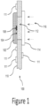
- Figure 1 illustrates a gas detector device of a gas detecting system in accordance with one or more embodiments of the present disclosure.
- the device 100 includes a microphone 102 having a front surface 104 and a sound collecting aperture 108, a gas cavity 112 formed in substrate 110 such that the gas cavity 112 is in gas communication with the aperture 108 and wherein the front surface forms a side surface of the gas cavity 112, and a 114 window abutting the substrate 110 to form a side surface of the gas cavity 112.
- the substrate may have electronic components 111 mounted on one or both side of its surfaces. These components can be related to the functioning of the gas detector or can be components not related to the function of the gas detector, but located proximate to the gas detector.
- the window can include optical characteristics that change the characteristics of the light passing through the window.
- the window can have a diffusing or collimating characteristic designed into the window.
- the window could also be a lens or waveguide.
- optical characteristics can be accomplished based on the formation of the interior of the window, the formation and/or preparation (e.g., polishing) of one or more sides of the window, and/or through the use of coatings applied to the window on one or more sides.
- the window can also be coated with optical films to enhance or retard the transmission of light at certain wavelengths. This may be beneficial in some embodiments to isolate or focus certain wavelengths for purposes of improving detection. For example, certain wavelengths that can be isolated or enhanced can be 3.3 and/or 3.4 micrometers for hydrocarbons, 4.3 micrometers for CO 2 , or 9 micrometers for ammonia, among others.
- the gas cavity (formed by other elements of the device, such as the one or more substrates, the window, and the microphone) is a closed cell that does not allow interaction with the ambient surroundings. Accordingly, the gas within the closed cell can be selected to enhance the sensitivity for the presence of a particular gas or a particular set of gases.
- the substrate 110 is a printed circuit board
- the structure comprising the substrate can be of multiple layers rather than a single substrate layer, as shown in Figure 1 .
- the microphone and/or the window can be attached to the substrate 110 such that the gas cavity 112 is hermetically sealed. Such embodiments allow for formation of a gas filled cavity which is fluidly connected to the microphone inlet port (i.e., aperture 108) but insulated from the ambient conditions.
- radiative power e.g., light from a light source
- radiative power e.g., light from a light source
- a small amount of heat can be generated.
- the heat causes a pressure rise which can be sensed by the microphone.
- the fill gas in the cavity 112 can be selected to optimize the sensitivity and/or temperature range of the detector, based on parameters such as specific heat, thermal conductivity, permeability, triple point, and/or chemical stability, among other parameters that can be utilized based upon the operating conditions of the detector.
- the fill gas is at least one of nitrogen, hydrogen, argon, krypton, xenon, hydrocarbons, fluorocarbons, or a mixture of above gases.
- the pressure of the fill gas can be less or larger than the ambient pressure.
- the fill gas pressure can range from 10kPa to 1000kPA (0.1 bar to 10 bar), insome embodiments.
- An advantage of the detector is the isolation of the microphone from the ambient surroundings, thus eliminating interferences and instabilities due to environmental variables such as acoustic noise, pressure, density, moisture, chemicals, and particulates that are in the ambient surroundings around the device.
- a PCB makes electrical interconnects to the microphone (e.g., through surface mount soldering pads) thus the detector can be an integral part of a PCB and connected to other components on the same board.
- a user could have several of these devices (e.g., on the same substrate, such as a PCB) each having different gases in their respective gas cavity and they could be inserted into a larger system, to accomplish gas detection.
- a single device e.g., the structure of Figure 1 or a similar structure
- a system e.g., a structure like that of Figure 2 or another suitable structure
- multiple devices could be used at the same time (e.g., either on the same substrate or on different substrates) to sense multiple gases or could have the same gas in the gas cavity and could provide redundancy, which could be beneficial as it would provide increased certainty that the gas detection was correct.
- Figure 2 illustrates a gas detector system in accordance with one or more embodiments of the present disclosure.
- Figure 2 shows a gas detector design which can be compact and have low power consumption in many implementations.
- the light wavelength detecting element 202 and an optical source 224 are face-to-face mounted on the opposite ends of a housing 222 with an optical cavity 232, which can have a reflective internal surface finish 226 to facilitate maximum light entry into the detector 200.
- the optical source can, for example, be one or more filament bulbs, microelectromechanical systems (MEMS) hotplates, light emitting diodes (LEDs), and/or lasers.
- MEMS microelectromechanical systems
- LEDs light emitting diodes
- lasers lasers
- the reflective surface does not need to be reflective to visible light in all applications, but rather, may be reflective to one or more wavelengths that will be used with respect to detecting the particular one or more gases within the gas cavity.
- the surface of the optical cavity may have a texture.
- the texture may provide a more homogeneous light pattern that is directed to the detector.
- the surface may be non-reflective.
- At least part of the walls of the housing 222 with the optical cavity 232 are permeable to ambient gases via permeable material, holes (e.g., openings 228), or porous media (porous at least to the wavelengths of light that will be useful for detection), thus the presence of gases of interest in the ambient surroundings that absorb the radiation could be detected by the detector when a reduction of received radiation at specific wavelengths (e.g., for example, wavelengths such as 3.3 or 3.4 micrometers for hydrocarbons, 4.3 micrometers for CO 2 , or 9 micrometers for ammonia, among others) is observed.
- specific wavelengths e.g., for example, wavelengths such as 3.3 or 3.4 micrometers for hydrocarbons, 4.3 micrometers for CO 2 , or 9 micrometers for ammonia, among others
- optical band-pass filters may be added as additional components in the optical path or a coating on the interior surface (nearer to the microphone) or the exterior surface 234 of the detector window. In some instances, even though the gas cavity has a particular gas therein, there may still be a need for filtering of ambient components that may have similar characteristics as the particular gas in the cavity.
- one or more filters such as thin film, applied coatings, filters physically separate from the window, or other types of filters, could be placed in the path of the light from the light source to filter out such ambient noise (characteristics that may be mistaken for the particular gas in the cavity) associated with these ambient components.
- ambient noise characteristics that may be mistaken for the particular gas in the cavity
- Such an implementation may also be done in applications having multiple gases within the cavity.
- ambient components that can be filtered can, for example, can include CO 2 , water vapor, or condensed water, among others.
- the optical source since the Golay cell is only sensitive to modulated optical intensity, the optical source must be modulated at a certain frequency, for example, a frequency in the 3 to 1000 Hz range.
- the gas detector of this configuration can be operated at extremely low power because the Golay cell is able to detect a very low level of radiative power thus the optical source can be energized at correspondingly low levels.
- Embodiments of the present disclosure can be constructed as a micro-Golay detector device with an elongate size (width of widest side of the microphone) of the microphone component being 2-5 mm. With such embodiments, these devices could be used in small and/or portable applications and such devices may have a lower power consumption as opposed to devices on the magnitude of 10-20 mm width dimension. Another benefit of a micro-Golay device is the reduced ability of contaminants to get into the device.
- the embodiments of the present disclosure can be used in a broad range of optical based gas detection including detection of flammable gases, toxic gases, and other environmentally relevant gases such as CO 2 and refrigerants.
- a Golay cell detector device can be used as a standalone detector for electromagnetic radiation from deep UV to terahertz frequencies, among other implementations.
Landscapes
- Physics & Mathematics (AREA)
- General Physics & Mathematics (AREA)
- Chemical & Material Sciences (AREA)
- Health & Medical Sciences (AREA)
- Life Sciences & Earth Sciences (AREA)
- Spectroscopy & Molecular Physics (AREA)
- Analytical Chemistry (AREA)
- Biochemistry (AREA)
- General Health & Medical Sciences (AREA)
- Immunology (AREA)
- Pathology (AREA)
- Engineering & Computer Science (AREA)
- Medicinal Chemistry (AREA)
- Food Science & Technology (AREA)
- Combustion & Propulsion (AREA)
- Investigating Or Analysing Materials By Optical Means (AREA)
Claims (6)
- Gasdetektionssystem (200), umfassend:
eine Gasdetektorvorrichtung (100) mit einer Golay-Zelle, die Golay-Zelle umfassend:ein Mikrofon (102), das eine Stirnfläche (104) mit einer Schallauffangöffnung (108) zum Aufnehmen von Schall aufweist;ein Substrat (110);einen Gashohlraum (112), der dazu konfiguriert ist, ein in dem Substrat (110) ausgebildetes erstes Gas zu detektieren, sodass der Gasholhlraum (112) in Gasverbindung mit der Schallauffangöffnung (108) steht und die Stirnfläche (104) eine Seitenfläche des Gashohlraums (112) bildet;wobei der Gashohlraum (112) ein Füllgas beinhaltet, das mindestens eines aus Wasserstoff, Argon, Stickstoff, Krypton, Xenon, Kohlenwasserstoffen oder Fluorkohlenwasserstoffen umfasst;wobei der Gashohlraum (112) so versiegelt ist, dass Gas von außen nicht in den Gashohlraum (112) eindringen kann, sobald dieser versiegelt ist;ein Fenster (114), das an das Substrat (110) angrenzt, um eine Seitenfläche des Gashohlraums (112) zu bilden, gekennzeichnet dadurch, dass das Substrat (110) eine Leiterplatte ist, und dadurch, dass das Mikrofon (102) elektrisch mit dem Substrat (110) verbunden ist; und dadurch, dass die Gasdetektorvorrichtung (100) austauschbar ist, um den Austausch der Gasdetektorvorrichtung (100) aus dem Gasdetektionssystem (200) zu ermöglichen. - Gasdetektionssystem (200) nach Anspruch 1, ferner umfassend eine Vielzahl von Golay-Zellen.
- Gasdetektionssystem (200) nach Anspruch 2, wobei die Vielzahl von Golay-Zellen dazu konfiguriert ist, eine Vielzahl von Gasen gleichzeitig zu erfassen.
- Gasdetektionssystem (200) nach Anspruch 2, ferner umfassend mindestens eine Lichtquelle (224).
- Gasdetektionssystem (200) nach Anspruch 4, wobei die mindestens eine Lichtquelle (224) eine Vielzahl von Lichtquellen entsprechend der Vielzahl von Golay-Zellen umfasst, und wobei jede Lichtquelle (224) der Vielzahl von Lichtquellen dazu konfiguriert ist, das Licht in Richtung einer entsprechenden Golay-Zelle der Vielzahl von Golay-Zellen zu lenken.
- Gasdetektionssystem (200) nach Anspruch 1, wobei das Mikrofon (102) von der Außenumgebung isoliert ist.
Applications Claiming Priority (3)
| Application Number | Priority Date | Filing Date | Title |
|---|---|---|---|
| US14/879,920 US9606049B1 (en) | 2015-10-09 | 2015-10-09 | Gas detector using a golay cell |
| PCT/US2016/055748 WO2017062617A1 (en) | 2015-10-09 | 2016-10-06 | Gas detector using a golay cell |
| EP16785292.0A EP3359934B1 (de) | 2015-10-09 | 2016-10-06 | Gasdetektor mit einer golay-zelle und verfahren zum erkennen eines gases mithilfe einer golay-zelle |
Related Parent Applications (2)
| Application Number | Title | Priority Date | Filing Date |
|---|---|---|---|
| EP16785292.0A Division-Into EP3359934B1 (de) | 2015-10-09 | 2016-10-06 | Gasdetektor mit einer golay-zelle und verfahren zum erkennen eines gases mithilfe einer golay-zelle |
| EP16785292.0A Division EP3359934B1 (de) | 2015-10-09 | 2016-10-06 | Gasdetektor mit einer golay-zelle und verfahren zum erkennen eines gases mithilfe einer golay-zelle |
Publications (2)
| Publication Number | Publication Date |
|---|---|
| EP4220133A1 EP4220133A1 (de) | 2023-08-02 |
| EP4220133B1 true EP4220133B1 (de) | 2025-01-01 |
Family
ID=57190230
Family Applications (2)
| Application Number | Title | Priority Date | Filing Date |
|---|---|---|---|
| EP16785292.0A Active EP3359934B1 (de) | 2015-10-09 | 2016-10-06 | Gasdetektor mit einer golay-zelle und verfahren zum erkennen eines gases mithilfe einer golay-zelle |
| EP23172560.7A Active EP4220133B1 (de) | 2015-10-09 | 2016-10-06 | Gasdetektionssystem bestehend aus einem gasdetektorgerät mit einer golay-zelle |
Family Applications Before (1)
| Application Number | Title | Priority Date | Filing Date |
|---|---|---|---|
| EP16785292.0A Active EP3359934B1 (de) | 2015-10-09 | 2016-10-06 | Gasdetektor mit einer golay-zelle und verfahren zum erkennen eines gases mithilfe einer golay-zelle |
Country Status (4)
| Country | Link |
|---|---|
| US (2) | US9606049B1 (de) |
| EP (2) | EP3359934B1 (de) |
| CN (2) | CN112485195B (de) |
| WO (1) | WO2017062617A1 (de) |
Families Citing this family (6)
| Publication number | Priority date | Publication date | Assignee | Title |
|---|---|---|---|---|
| US9513261B2 (en) * | 2013-10-14 | 2016-12-06 | Infineon Technologies Ag | Photoacoustic gas sensor device and a method for analyzing gas |
| US10883875B2 (en) | 2015-03-05 | 2021-01-05 | Honeywell International Inc. | Use of selected glass types and glass thicknesses in the optical path to remove cross sensitivity to water absorption peaks |
| US10458900B2 (en) | 2015-09-10 | 2019-10-29 | Honeywell International Inc. | Gas detector with normalized response and improved sensitivity |
| EP3359933A1 (de) | 2015-10-09 | 2018-08-15 | Honeywell International Inc. | Detektor für elektromagnetische strahlung mit einer planaren golay-zelle |
| US9606049B1 (en) | 2015-10-09 | 2017-03-28 | Honeywell International Inc. | Gas detector using a golay cell |
| US11119037B2 (en) | 2017-10-30 | 2021-09-14 | Honeywell International Inc. | Small form factor spectrally selective absorber with high acceptance angle for use in gas detection |
Family Cites Families (22)
| Publication number | Priority date | Publication date | Assignee | Title |
|---|---|---|---|---|
| US4738266A (en) * | 1983-05-09 | 1988-04-19 | Thatcher John B | Apnoea monitor |
| WO1985003574A1 (fr) * | 1984-02-07 | 1985-08-15 | Oskar Oehler | Installation pour la detection photo-acoustique de gaz |
| US4891629A (en) * | 1988-05-16 | 1990-01-02 | General Electric Company | Binary gas analyzer instrument and analysis method |
| JPH05172627A (ja) * | 1991-12-24 | 1993-07-09 | Jasco Corp | 気体膨脹型エネルギー測定装置 |
| JPH05172628A (ja) * | 1991-12-24 | 1993-07-09 | Jasco Corp | 気体膨脹型エネルギー測定装置 |
| JPH08184501A (ja) * | 1994-12-30 | 1996-07-16 | Horiba Ltd | マイクロゴーレイセル |
| NO301854B1 (no) * | 1996-09-19 | 1997-12-15 | Nyfotek As | Foto-akustisk infraröd detektor |
| JPH10142145A (ja) * | 1996-11-06 | 1998-05-29 | Yazaki Corp | ガス検出方法及びその装置 |
| JPH10332579A (ja) * | 1997-05-27 | 1998-12-18 | Jasco Corp | ゴレイセル並びにそれを用いた13c計測装置 |
| JPH1172428A (ja) * | 1997-08-28 | 1999-03-16 | Jasco Corp | ニューマッチク・ゴレイセル |
| CN1103498C (zh) * | 1999-01-28 | 2003-03-19 | 北京工业大学 | 红外探测器 |
| JP2002328116A (ja) * | 2001-04-27 | 2002-11-15 | Yamatake Corp | 光音響ガスセンサ |
| FI118548B (fi) * | 2002-09-30 | 2007-12-14 | Noveltech Solutions Ltd | Fotoakustinen detektori |
| US7045784B1 (en) * | 2003-12-18 | 2006-05-16 | The United States Of America As Represented By The Secretary Of The Navy | Method and apparatus for micro-Golay cell infrared detectors |
| US7423258B2 (en) * | 2005-02-04 | 2008-09-09 | Baker Hughes Incorporated | Method and apparatus for analyzing a downhole fluid using a thermal detector |
| US20080277586A1 (en) * | 2007-05-07 | 2008-11-13 | Dennis Cardinale | Low-Power Fast Infrared Gas Sensor, Hand Held Gas Leak Detector, and Gas Monitor Utilizing Absorptive-Photo-Acoustic Detection |
| EP2060891A1 (de) * | 2007-11-12 | 2009-05-20 | Technische Universiteit Delft | Infrarotsensor mit Golay-Zelle |
| IT1400090B1 (it) * | 2010-05-06 | 2013-05-17 | Eurotecnica Melamine Luxemburg Zweigniederlassung In Ittigen | Procedimento a basso consumo energetico per la produzione di melammina ad elevata purezza tramite pirolisi dell'urea, e relativa apparecchiatura |
| US8695402B2 (en) * | 2010-06-03 | 2014-04-15 | Honeywell International Inc. | Integrated IR source and acoustic detector for photoacoustic gas sensor |
| JP2015041545A (ja) * | 2013-08-22 | 2015-03-02 | スタンレー電気株式会社 | 赤外光源、および、それを用いたガス検出装置 |
| CN104458642A (zh) * | 2014-12-03 | 2015-03-25 | 天津大学 | 快速太赫兹连续波扫描成像系统及方法 |
| US9606049B1 (en) | 2015-10-09 | 2017-03-28 | Honeywell International Inc. | Gas detector using a golay cell |
-
2015
- 2015-10-09 US US14/879,920 patent/US9606049B1/en active Active
-
2016
- 2016-10-06 EP EP16785292.0A patent/EP3359934B1/de active Active
- 2016-10-06 EP EP23172560.7A patent/EP4220133B1/de active Active
- 2016-10-06 CN CN202011436813.7A patent/CN112485195B/zh active Active
- 2016-10-06 CN CN201680071989.2A patent/CN108369139B/zh active Active
- 2016-10-06 WO PCT/US2016/055748 patent/WO2017062617A1/en not_active Ceased
-
2017
- 2017-01-06 US US15/400,554 patent/US9829428B2/en active Active
Also Published As
| Publication number | Publication date |
|---|---|
| US20170102318A1 (en) | 2017-04-13 |
| WO2017062617A1 (en) | 2017-04-13 |
| CN108369139A (zh) | 2018-08-03 |
| EP3359934B1 (de) | 2023-06-21 |
| US20170115207A1 (en) | 2017-04-27 |
| EP3359934A1 (de) | 2018-08-15 |
| US9829428B2 (en) | 2017-11-28 |
| CN112485195B (zh) | 2025-10-10 |
| US9606049B1 (en) | 2017-03-28 |
| CN112485195A (zh) | 2021-03-12 |
| EP4220133A1 (de) | 2023-08-02 |
| CN108369139B (zh) | 2020-12-22 |
Similar Documents
| Publication | Publication Date | Title |
|---|---|---|
| US9829428B2 (en) | Gas detector using a Golay cell | |
| KR101372989B1 (ko) | 적외선 불꽃 검출기 | |
| US10302554B2 (en) | Acoustic wave detector | |
| EP3198261B1 (de) | Optischer gasmesser mit explosionssicherem gehäuse | |
| US10393591B2 (en) | Electromagnetic radiation detector using a planar Golay cell | |
| WO1997025613A1 (en) | Passive infrared analysis gas sensors and applicable multichannel detector assemblies | |
| EP1299710A2 (de) | Diffusionsartiger ndir gasanalysator mit schneller ansprechzeit aufgrund von konvektionsströmung | |
| JP2005539229A (ja) | 物質を検出するための装置および物質の濃度を測定するための装置 | |
| WO2004023113A1 (en) | Gas sensors | |
| WO1999022221A1 (en) | Diffusion-type ndir gas analyzer with convection flow | |
| KR20110092354A (ko) | 가스 센서 장치 | |
| CN102301224A (zh) | 设有发射源监测器的吸收光学探测器 | |
| US11353431B2 (en) | Photoacoustic sensor | |
| US20220042903A1 (en) | Gas sensor with two switchable filters and method for operating such a gas sensor | |
| KR20180070606A (ko) | 노출되지 않은 전극을 갖는 가스 방전 셀 내에서 추적 가스의 광학 검출 | |
| Pinet et al. | Sensitive chemical optic sensor using birefringent porous glass for the detection of volatile organic compounds | |
| CN115753608A (zh) | 一种单光源复合传感器 | |
| US20150000413A1 (en) | Outer part for a device and device | |
| RU2138856C1 (ru) | Устройство сигнализации пожаро-взрывоопасной ситуации в летательных аппаратах | |
| US20200333244A1 (en) | Small form factor spectrally selective absorber with high acceptance angle for use in gas detection | |
| KR20140147622A (ko) | 공진 반사광 필터와 이를 구비한 가스 감지장치 | |
| Lammel et al. | Tunable Optical Filter and IR Gas Spectroscopy |
Legal Events
| Date | Code | Title | Description |
|---|---|---|---|
| PUAI | Public reference made under article 153(3) epc to a published international application that has entered the european phase |
Free format text: ORIGINAL CODE: 0009012 |
|
| STAA | Information on the status of an ep patent application or granted ep patent |
Free format text: STATUS: THE APPLICATION HAS BEEN PUBLISHED |
|
| AC | Divisional application: reference to earlier application |
Ref document number: 3359934 Country of ref document: EP Kind code of ref document: P |
|
| AK | Designated contracting states |
Kind code of ref document: A1 Designated state(s): AL AT BE BG CH CY CZ DE DK EE ES FI FR GB GR HR HU IE IS IT LI LT LU LV MC MK MT NL NO PL PT RO RS SE SI SK SM TR |
|
| STAA | Information on the status of an ep patent application or granted ep patent |
Free format text: STATUS: REQUEST FOR EXAMINATION WAS MADE |
|
| 17P | Request for examination filed |
Effective date: 20240131 |
|
| RBV | Designated contracting states (corrected) |
Designated state(s): AL AT BE BG CH CY CZ DE DK EE ES FI FR GB GR HR HU IE IS IT LI LT LU LV MC MK MT NL NO PL PT RO RS SE SI SK SM TR |
|
| GRAP | Despatch of communication of intention to grant a patent |
Free format text: ORIGINAL CODE: EPIDOSNIGR1 |
|
| STAA | Information on the status of an ep patent application or granted ep patent |
Free format text: STATUS: GRANT OF PATENT IS INTENDED |
|
| RIC1 | Information provided on ipc code assigned before grant |
Ipc: G01J 5/42 20060101ALI20240228BHEP Ipc: G01N 33/00 20060101ALI20240228BHEP Ipc: G01N 21/17 20060101ALI20240228BHEP Ipc: G01N 21/37 20060101AFI20240228BHEP |
|
| RIN1 | Information on inventor provided before grant (corrected) |
Inventor name: WATTS, RODNEY R. Inventor name: WILLETT, MARTIN Inventor name: MARTA, TERESA M. Inventor name: YANG, WEI |
|
| INTG | Intention to grant announced |
Effective date: 20240318 |
|
| GRAJ | Information related to disapproval of communication of intention to grant by the applicant or resumption of examination proceedings by the epo deleted |
Free format text: ORIGINAL CODE: EPIDOSDIGR1 |
|
| STAA | Information on the status of an ep patent application or granted ep patent |
Free format text: STATUS: REQUEST FOR EXAMINATION WAS MADE |
|
| GRAS | Grant fee paid |
Free format text: ORIGINAL CODE: EPIDOSNIGR3 |
|
| STAA | Information on the status of an ep patent application or granted ep patent |
Free format text: STATUS: GRANT OF PATENT IS INTENDED |
|
| GRAP | Despatch of communication of intention to grant a patent |
Free format text: ORIGINAL CODE: EPIDOSNIGR1 |
|
| INTC | Intention to grant announced (deleted) | ||
| INTG | Intention to grant announced |
Effective date: 20240801 |
|
| GRAA | (expected) grant |
Free format text: ORIGINAL CODE: 0009210 |
|
| STAA | Information on the status of an ep patent application or granted ep patent |
Free format text: STATUS: THE PATENT HAS BEEN GRANTED |
|
| AC | Divisional application: reference to earlier application |
Ref document number: 3359934 Country of ref document: EP Kind code of ref document: P |
|
| AK | Designated contracting states |
Kind code of ref document: B1 Designated state(s): AL AT BE BG CH CY CZ DE DK EE ES FI FR GB GR HR HU IE IS IT LI LT LU LV MC MK MT NL NO PL PT RO RS SE SI SK SM TR |
|
| REG | Reference to a national code |
Ref country code: GB Ref legal event code: FG4D |
|
| REG | Reference to a national code |
Ref country code: CH Ref legal event code: EP |
|
| REG | Reference to a national code |
Ref country code: DE Ref legal event code: R096 Ref document number: 602016090874 Country of ref document: DE |
|
| REG | Reference to a national code |
Ref country code: IE Ref legal event code: FG4D |
|
| REG | Reference to a national code |
Ref country code: LT Ref legal event code: MG9D |
|
| REG | Reference to a national code |
Ref country code: NL Ref legal event code: MP Effective date: 20250101 |
|
| REG | Reference to a national code |
Ref country code: AT Ref legal event code: MK05 Ref document number: 1756701 Country of ref document: AT Kind code of ref document: T Effective date: 20250101 |
|
| PG25 | Lapsed in a contracting state [announced via postgrant information from national office to epo] |
Ref country code: NL Free format text: LAPSE BECAUSE OF FAILURE TO SUBMIT A TRANSLATION OF THE DESCRIPTION OR TO PAY THE FEE WITHIN THE PRESCRIBED TIME-LIMIT Effective date: 20250101 |
|
| PG25 | Lapsed in a contracting state [announced via postgrant information from national office to epo] |
Ref country code: FI Free format text: LAPSE BECAUSE OF FAILURE TO SUBMIT A TRANSLATION OF THE DESCRIPTION OR TO PAY THE FEE WITHIN THE PRESCRIBED TIME-LIMIT Effective date: 20250101 |
|
| PG25 | Lapsed in a contracting state [announced via postgrant information from national office to epo] |
Ref country code: PL Free format text: LAPSE BECAUSE OF FAILURE TO SUBMIT A TRANSLATION OF THE DESCRIPTION OR TO PAY THE FEE WITHIN THE PRESCRIBED TIME-LIMIT Effective date: 20250101 |
|
| PG25 | Lapsed in a contracting state [announced via postgrant information from national office to epo] |
Ref country code: ES Free format text: LAPSE BECAUSE OF FAILURE TO SUBMIT A TRANSLATION OF THE DESCRIPTION OR TO PAY THE FEE WITHIN THE PRESCRIBED TIME-LIMIT Effective date: 20250101 |
|
| PG25 | Lapsed in a contracting state [announced via postgrant information from national office to epo] |
Ref country code: IS Free format text: LAPSE BECAUSE OF FAILURE TO SUBMIT A TRANSLATION OF THE DESCRIPTION OR TO PAY THE FEE WITHIN THE PRESCRIBED TIME-LIMIT Effective date: 20250501 Ref country code: NO Free format text: LAPSE BECAUSE OF FAILURE TO SUBMIT A TRANSLATION OF THE DESCRIPTION OR TO PAY THE FEE WITHIN THE PRESCRIBED TIME-LIMIT Effective date: 20250401 |
|
| PG25 | Lapsed in a contracting state [announced via postgrant information from national office to epo] |
Ref country code: HR Free format text: LAPSE BECAUSE OF FAILURE TO SUBMIT A TRANSLATION OF THE DESCRIPTION OR TO PAY THE FEE WITHIN THE PRESCRIBED TIME-LIMIT Effective date: 20250101 |
|
| PG25 | Lapsed in a contracting state [announced via postgrant information from national office to epo] |
Ref country code: LV Free format text: LAPSE BECAUSE OF FAILURE TO SUBMIT A TRANSLATION OF THE DESCRIPTION OR TO PAY THE FEE WITHIN THE PRESCRIBED TIME-LIMIT Effective date: 20250101 Ref country code: PT Free format text: LAPSE BECAUSE OF FAILURE TO SUBMIT A TRANSLATION OF THE DESCRIPTION OR TO PAY THE FEE WITHIN THE PRESCRIBED TIME-LIMIT Effective date: 20250502 |
|
| PG25 | Lapsed in a contracting state [announced via postgrant information from national office to epo] |
Ref country code: BG Free format text: LAPSE BECAUSE OF FAILURE TO SUBMIT A TRANSLATION OF THE DESCRIPTION OR TO PAY THE FEE WITHIN THE PRESCRIBED TIME-LIMIT Effective date: 20250101 Ref country code: GR Free format text: LAPSE BECAUSE OF FAILURE TO SUBMIT A TRANSLATION OF THE DESCRIPTION OR TO PAY THE FEE WITHIN THE PRESCRIBED TIME-LIMIT Effective date: 20250402 |
|
| PG25 | Lapsed in a contracting state [announced via postgrant information from national office to epo] |
Ref country code: AT Free format text: LAPSE BECAUSE OF FAILURE TO SUBMIT A TRANSLATION OF THE DESCRIPTION OR TO PAY THE FEE WITHIN THE PRESCRIBED TIME-LIMIT Effective date: 20250101 |
|
| PG25 | Lapsed in a contracting state [announced via postgrant information from national office to epo] |
Ref country code: CZ Free format text: LAPSE BECAUSE OF FAILURE TO SUBMIT A TRANSLATION OF THE DESCRIPTION OR TO PAY THE FEE WITHIN THE PRESCRIBED TIME-LIMIT Effective date: 20250101 |
|
| PG25 | Lapsed in a contracting state [announced via postgrant information from national office to epo] |
Ref country code: SE Free format text: LAPSE BECAUSE OF FAILURE TO SUBMIT A TRANSLATION OF THE DESCRIPTION OR TO PAY THE FEE WITHIN THE PRESCRIBED TIME-LIMIT Effective date: 20250101 |
|
| REG | Reference to a national code |
Ref country code: DE Ref legal event code: R097 Ref document number: 602016090874 Country of ref document: DE |
|
| PG25 | Lapsed in a contracting state [announced via postgrant information from national office to epo] |
Ref country code: SM Free format text: LAPSE BECAUSE OF FAILURE TO SUBMIT A TRANSLATION OF THE DESCRIPTION OR TO PAY THE FEE WITHIN THE PRESCRIBED TIME-LIMIT Effective date: 20250101 |
|
| PG25 | Lapsed in a contracting state [announced via postgrant information from national office to epo] |
Ref country code: DK Free format text: LAPSE BECAUSE OF FAILURE TO SUBMIT A TRANSLATION OF THE DESCRIPTION OR TO PAY THE FEE WITHIN THE PRESCRIBED TIME-LIMIT Effective date: 20250101 |
|
| PG25 | Lapsed in a contracting state [announced via postgrant information from national office to epo] |
Ref country code: IT Free format text: LAPSE BECAUSE OF FAILURE TO SUBMIT A TRANSLATION OF THE DESCRIPTION OR TO PAY THE FEE WITHIN THE PRESCRIBED TIME-LIMIT Effective date: 20250101 |
|
| PG25 | Lapsed in a contracting state [announced via postgrant information from national office to epo] |
Ref country code: EE Free format text: LAPSE BECAUSE OF FAILURE TO SUBMIT A TRANSLATION OF THE DESCRIPTION OR TO PAY THE FEE WITHIN THE PRESCRIBED TIME-LIMIT Effective date: 20250101 |
|
| PG25 | Lapsed in a contracting state [announced via postgrant information from national office to epo] |
Ref country code: RO Free format text: LAPSE BECAUSE OF FAILURE TO SUBMIT A TRANSLATION OF THE DESCRIPTION OR TO PAY THE FEE WITHIN THE PRESCRIBED TIME-LIMIT Effective date: 20250101 |
|
| PG25 | Lapsed in a contracting state [announced via postgrant information from national office to epo] |
Ref country code: SK Free format text: LAPSE BECAUSE OF FAILURE TO SUBMIT A TRANSLATION OF THE DESCRIPTION OR TO PAY THE FEE WITHIN THE PRESCRIBED TIME-LIMIT Effective date: 20250101 |
|
| PLBE | No opposition filed within time limit |
Free format text: ORIGINAL CODE: 0009261 |
|
| STAA | Information on the status of an ep patent application or granted ep patent |
Free format text: STATUS: NO OPPOSITION FILED WITHIN TIME LIMIT |
|
| REG | Reference to a national code |
Ref country code: CH Ref legal event code: L10 Free format text: ST27 STATUS EVENT CODE: U-0-0-L10-L00 (AS PROVIDED BY THE NATIONAL OFFICE) Effective date: 20251112 |
|
| 26N | No opposition filed |
Effective date: 20251002 |
|
| PGFP | Annual fee paid to national office [announced via postgrant information from national office to epo] |
Ref country code: DE Payment date: 20251028 Year of fee payment: 10 |
|
| PGFP | Annual fee paid to national office [announced via postgrant information from national office to epo] |
Ref country code: GB Payment date: 20251023 Year of fee payment: 10 |
|
| REG | Reference to a national code |
Ref country code: CH Ref legal event code: H13 Free format text: ST27 STATUS EVENT CODE: U-0-0-H10-H13 (AS PROVIDED BY THE NATIONAL OFFICE) Effective date: 20260527 |
|
| PG25 | Lapsed in a contracting state [announced via postgrant information from national office to epo] |
Ref country code: LU Free format text: LAPSE BECAUSE OF NON-PAYMENT OF DUE FEES Effective date: 20251006 |
|
| REG | Reference to a national code |
Ref country code: BE Ref legal event code: MM Effective date: 20251031 |
|
| PG25 | Lapsed in a contracting state [announced via postgrant information from national office to epo] |
Ref country code: LT Free format text: LAPSE BECAUSE OF FAILURE TO SUBMIT A TRANSLATION OF THE DESCRIPTION OR TO PAY THE FEE WITHIN THE PRESCRIBED TIME-LIMIT Effective date: 20250101 |
|
| PG25 | Lapsed in a contracting state [announced via postgrant information from national office to epo] |
Ref country code: MC Free format text: LAPSE BECAUSE OF FAILURE TO SUBMIT A TRANSLATION OF THE DESCRIPTION OR TO PAY THE FEE WITHIN THE PRESCRIBED TIME-LIMIT Effective date: 20250101 |
|
| PG25 | Lapsed in a contracting state [announced via postgrant information from national office to epo] |
Ref country code: RS Free format text: LAPSE BECAUSE OF FAILURE TO SUBMIT A TRANSLATION OF THE DESCRIPTION OR TO PAY THE FEE WITHIN THE PRESCRIBED TIME-LIMIT Effective date: 20250101 |
|
| PG25 | Lapsed in a contracting state [announced via postgrant information from national office to epo] |
Ref country code: CH Free format text: LAPSE BECAUSE OF NON-PAYMENT OF DUE FEES Effective date: 20251031 Ref country code: BE Free format text: LAPSE BECAUSE OF NON-PAYMENT OF DUE FEES Effective date: 20251031 |
|
| PG25 | Lapsed in a contracting state [announced via postgrant information from national office to epo] |
Ref country code: FR Free format text: LAPSE BECAUSE OF NON-PAYMENT OF DUE FEES Effective date: 20251031 |