EP4218641B1 - Optimierung der energieabgabe für verschiedene anwendungen - Google Patents
Optimierung der energieabgabe für verschiedene anwendungen Download PDFInfo
- Publication number
- EP4218641B1 EP4218641B1 EP23178276.4A EP23178276A EP4218641B1 EP 4218641 B1 EP4218641 B1 EP 4218641B1 EP 23178276 A EP23178276 A EP 23178276A EP 4218641 B1 EP4218641 B1 EP 4218641B1
- Authority
- EP
- European Patent Office
- Prior art keywords
- electrode
- energy
- electric field
- packets
- delivered
- Prior art date
- Legal status (The legal status is an assumption and is not a legal conclusion. Google has not performed a legal analysis and makes no representation as to the accuracy of the status listed.)
- Active
Links
Images


Classifications
-
- A—HUMAN NECESSITIES
- A61—MEDICAL OR VETERINARY SCIENCE; HYGIENE
- A61N—ELECTROTHERAPY; MAGNETOTHERAPY; RADIATION THERAPY; ULTRASOUND THERAPY
- A61N1/00—Electrotherapy; Circuits therefor
- A61N1/02—Details
- A61N1/04—Electrodes
- A61N1/05—Electrodes for implantation or insertion into the body, e.g. heart electrode
- A61N1/056—Transvascular endocardial electrode systems
- A61N1/0565—Electrode heads
-
- A—HUMAN NECESSITIES
- A61—MEDICAL OR VETERINARY SCIENCE; HYGIENE
- A61B—DIAGNOSIS; SURGERY; IDENTIFICATION
- A61B18/00—Surgical instruments, devices or methods for transferring non-mechanical forms of energy to or from the body
- A61B18/04—Surgical instruments, devices or methods for transferring non-mechanical forms of energy to or from the body by heating
- A61B18/12—Surgical instruments, devices or methods for transferring non-mechanical forms of energy to or from the body by heating by passing a current through the tissue to be heated, e.g. high-frequency current
- A61B18/14—Probes or electrodes therefor
- A61B18/1492—Probes or electrodes therefor having a flexible, catheter-like structure, e.g. for heart ablation
-
- A—HUMAN NECESSITIES
- A61—MEDICAL OR VETERINARY SCIENCE; HYGIENE
- A61B—DIAGNOSIS; SURGERY; IDENTIFICATION
- A61B18/00—Surgical instruments, devices or methods for transferring non-mechanical forms of energy to or from the body
- A61B18/04—Surgical instruments, devices or methods for transferring non-mechanical forms of energy to or from the body by heating
- A61B18/12—Surgical instruments, devices or methods for transferring non-mechanical forms of energy to or from the body by heating by passing a current through the tissue to be heated, e.g. high-frequency current
-
- A—HUMAN NECESSITIES
- A61—MEDICAL OR VETERINARY SCIENCE; HYGIENE
- A61B—DIAGNOSIS; SURGERY; IDENTIFICATION
- A61B18/00—Surgical instruments, devices or methods for transferring non-mechanical forms of energy to or from the body
-
- A—HUMAN NECESSITIES
- A61—MEDICAL OR VETERINARY SCIENCE; HYGIENE
- A61B—DIAGNOSIS; SURGERY; IDENTIFICATION
- A61B18/00—Surgical instruments, devices or methods for transferring non-mechanical forms of energy to or from the body
- A61B18/04—Surgical instruments, devices or methods for transferring non-mechanical forms of energy to or from the body by heating
- A61B18/12—Surgical instruments, devices or methods for transferring non-mechanical forms of energy to or from the body by heating by passing a current through the tissue to be heated, e.g. high-frequency current
- A61B18/14—Probes or electrodes therefor
-
- A—HUMAN NECESSITIES
- A61—MEDICAL OR VETERINARY SCIENCE; HYGIENE
- A61N—ELECTROTHERAPY; MAGNETOTHERAPY; RADIATION THERAPY; ULTRASOUND THERAPY
- A61N1/00—Electrotherapy; Circuits therefor
- A61N1/18—Applying electric currents by contact electrodes
- A61N1/20—Applying electric currents by contact electrodes continuous direct currents
- A61N1/205—Applying electric currents by contact electrodes continuous direct currents for promoting a biological process
-
- A—HUMAN NECESSITIES
- A61—MEDICAL OR VETERINARY SCIENCE; HYGIENE
- A61N—ELECTROTHERAPY; MAGNETOTHERAPY; RADIATION THERAPY; ULTRASOUND THERAPY
- A61N1/00—Electrotherapy; Circuits therefor
- A61N1/18—Applying electric currents by contact electrodes
- A61N1/32—Applying electric currents by contact electrodes alternating or intermittent currents
- A61N1/36—Applying electric currents by contact electrodes alternating or intermittent currents for stimulation
- A61N1/362—Heart stimulators
- A61N1/37—Monitoring; Protecting
-
- A—HUMAN NECESSITIES
- A61—MEDICAL OR VETERINARY SCIENCE; HYGIENE
- A61B—DIAGNOSIS; SURGERY; IDENTIFICATION
- A61B18/00—Surgical instruments, devices or methods for transferring non-mechanical forms of energy to or from the body
- A61B2018/00053—Mechanical features of the instrument of device
- A61B2018/00214—Expandable means emitting energy, e.g. by elements carried thereon
- A61B2018/00267—Expandable means emitting energy, e.g. by elements carried thereon having a basket shaped structure
-
- A—HUMAN NECESSITIES
- A61—MEDICAL OR VETERINARY SCIENCE; HYGIENE
- A61B—DIAGNOSIS; SURGERY; IDENTIFICATION
- A61B18/00—Surgical instruments, devices or methods for transferring non-mechanical forms of energy to or from the body
- A61B2018/00315—Surgical instruments, devices or methods for transferring non-mechanical forms of energy to or from the body for treatment of particular body parts
- A61B2018/00345—Vascular system
- A61B2018/00351—Heart
-
- A—HUMAN NECESSITIES
- A61—MEDICAL OR VETERINARY SCIENCE; HYGIENE
- A61B—DIAGNOSIS; SURGERY; IDENTIFICATION
- A61B18/00—Surgical instruments, devices or methods for transferring non-mechanical forms of energy to or from the body
- A61B2018/00315—Surgical instruments, devices or methods for transferring non-mechanical forms of energy to or from the body for treatment of particular body parts
- A61B2018/00541—Lung or bronchi
-
- A—HUMAN NECESSITIES
- A61—MEDICAL OR VETERINARY SCIENCE; HYGIENE
- A61B—DIAGNOSIS; SURGERY; IDENTIFICATION
- A61B18/00—Surgical instruments, devices or methods for transferring non-mechanical forms of energy to or from the body
- A61B2018/00571—Surgical instruments, devices or methods for transferring non-mechanical forms of energy to or from the body for achieving a particular surgical effect
- A61B2018/00577—Ablation
-
- A—HUMAN NECESSITIES
- A61—MEDICAL OR VETERINARY SCIENCE; HYGIENE
- A61B—DIAGNOSIS; SURGERY; IDENTIFICATION
- A61B18/00—Surgical instruments, devices or methods for transferring non-mechanical forms of energy to or from the body
- A61B2018/00636—Sensing and controlling the application of energy
- A61B2018/00696—Controlled or regulated parameters
- A61B2018/00767—Voltage
-
- A—HUMAN NECESSITIES
- A61—MEDICAL OR VETERINARY SCIENCE; HYGIENE
- A61B—DIAGNOSIS; SURGERY; IDENTIFICATION
- A61B18/00—Surgical instruments, devices or methods for transferring non-mechanical forms of energy to or from the body
- A61B18/04—Surgical instruments, devices or methods for transferring non-mechanical forms of energy to or from the body by heating
- A61B18/12—Surgical instruments, devices or methods for transferring non-mechanical forms of energy to or from the body by heating by passing a current through the tissue to be heated, e.g. high-frequency current
- A61B18/1206—Generators therefor
- A61B2018/124—Generators therefor switching the output to different electrodes, e.g. sequentially
-
- A—HUMAN NECESSITIES
- A61—MEDICAL OR VETERINARY SCIENCE; HYGIENE
- A61B—DIAGNOSIS; SURGERY; IDENTIFICATION
- A61B18/00—Surgical instruments, devices or methods for transferring non-mechanical forms of energy to or from the body
- A61B18/04—Surgical instruments, devices or methods for transferring non-mechanical forms of energy to or from the body by heating
- A61B18/12—Surgical instruments, devices or methods for transferring non-mechanical forms of energy to or from the body by heating by passing a current through the tissue to be heated, e.g. high-frequency current
- A61B18/14—Probes or electrodes therefor
- A61B2018/1465—Deformable electrodes
-
- A—HUMAN NECESSITIES
- A61—MEDICAL OR VETERINARY SCIENCE; HYGIENE
- A61B—DIAGNOSIS; SURGERY; IDENTIFICATION
- A61B18/00—Surgical instruments, devices or methods for transferring non-mechanical forms of energy to or from the body
- A61B18/04—Surgical instruments, devices or methods for transferring non-mechanical forms of energy to or from the body by heating
- A61B18/12—Surgical instruments, devices or methods for transferring non-mechanical forms of energy to or from the body by heating by passing a current through the tissue to be heated, e.g. high-frequency current
- A61B18/14—Probes or electrodes therefor
- A61B2018/1467—Probes or electrodes therefor using more than two electrodes on a single probe
-
- A—HUMAN NECESSITIES
- A61—MEDICAL OR VETERINARY SCIENCE; HYGIENE
- A61B—DIAGNOSIS; SURGERY; IDENTIFICATION
- A61B18/00—Surgical instruments, devices or methods for transferring non-mechanical forms of energy to or from the body
- A61B18/04—Surgical instruments, devices or methods for transferring non-mechanical forms of energy to or from the body by heating
- A61B18/12—Surgical instruments, devices or methods for transferring non-mechanical forms of energy to or from the body by heating by passing a current through the tissue to be heated, e.g. high-frequency current
- A61B18/14—Probes or electrodes therefor
- A61B2018/1475—Electrodes retractable in or deployable from a housing
Definitions
- Various devices and methods have been developed to deliver therapeutic energy to the body for the treatment of diseases and afflictions.
- such delivery is to tissues within a body lumen, passageway or similar anatomy, so as to treat diseased tissue along or within the walls of the passageway, or so as to affect diseases which are associated with a passageway or reachable through a passageway.
- Such devices typically include a flexible elongate shaft, so as to traverse tortuous luminal anatomy, and an energy delivery element mounted thereon to deliver such energy to remote or enclosed locations such as body lumens.
- Such devices have been developed to treat, for example, passageways of the lungs or blood vessels of the vasculature.
- EP 2736432 describes a medical system including a catheter body, an elongate body disposed in the catheter body, an expandable element having a proximal portion coupled to the catheter body and the distal portion coupled to the elongate body, the distal portion of the expandable element defining the distal most portion of the medical device, a mesh or array of longitudinal splines substantially surrounding the expandable element, at least a portion of the expandable splines being electrically conductive and a coolant source in fluid communication with the expandable element.
- US 9125666 describes a catheter and catheter system for eccentric remodeling and/or removal of atherosclerotic material of a blood vessel of a patient including an elongate flexible catheter body with a radially expandable structure.
- a plurality of electrodes or other electrosurgical energy delivery surfaces can radially engage atherosclerotic material when the structure expands.
- An atherosclerotic material detector near the distal end of the catheter body may measure circumferential atherosclerotic material distribution, and a power source selectively energizes the electrodes to eccentrically remodel the measured atherosclerotic material
- EP 2661236 describes a method of ablating an epicardial tissue region, including positioning a medical device adjacent the epicardial tissue region, the medical device having a first electrode, a second electrode, and a third electrode located in between the first and second electrodes, delivering an irrigation fluid to the tissue region, and ablating at least a portion of the tissue region by sequentially activating the third electrode in a monopolar radiofrequency delivery mode and activating the first and second electrodes in a bi-polar radio frequency delivery mode.
- a method is provided of treating a passageway within a body wherein the passageway has an inner circumference, the method comprising: positioning a plurality of electrodes within the passageway so that the plurality of electrodes spans the inner circumference of the passageway; creating a first treatment area along a first portion of the inner circumference of the passageway by providing pulsed electric field energy to at least one of the plurality of electrodes so as to prioritize energy delivery through the at least one of the plurality of electrodes to the first treatment area; and creating at least one additional treatment area along at least one additional portion of the inner circumference of the passageway by providing pulsed electric field energy to at least one of the plurality of electrodes so as to prioritize energy delivery through the at least one of the plurality of electrodes to the at least one additional treatment area, wherein the first portion and the at least one additional portion extends along the inner circumference so as to create a functionally continuous treatment area spanning the inner circumference.
- the passageway is disposed within a heart and the functionally continuous treatment area comprises an electrical disconnection between a pulmonary vein and a left atrium so as to treat arrhythmia.
- the passageway comprises the pulmonary vein.
- the functionally continuous treatment area comprises a transmural lesion.
- the passageway comprises an airway within a lung and the functionally continuous treatment area creates a vacancy of cell types while maintaining a cartilage layer of the airway.
- the cell types include epithelial cells, goblet cells and/or submucosal gland cells.
- the functionally continuous treatment area has a depth of up to and not beyond 2.5 cm.
- the pulsed electric field energy is biphasic.
- creating the first treatment area along the first portion of the inner circumference of the passageway is achieved by providing pulsed electric field energy to the at least one of the plurality of electrodes for less than or equal to 10,000us.
- creating the first treatment area along the first portion of the inner circumference of the passageway is achieved by providing pulsed electric field energy to the at least one of the plurality of electrodes for less than or equal to 500us.
- creating the first treatment area along the first portion of the inner circumference of the passageway is achieved by providing pulsed electric field energy to the at least one of the plurality of electrodes for 5us-50us.
- the pulsed electric field energy is comprised of less than or equal to 1000 packets, 40-500 packets, or up to 10 packets. In some embodiments, the pulsed electric field energy is delivered in a monopolar arrangement.
- the at least one additional portion comprises two to seven additional portions.
- the pulsed electric field energy is provided to the plurality of electrodes in a manner so that the first treatment area and the at least one additional treatment areas are created in series. In some embodiments, the first treatment area and the at least one additional treatment areas overlap.
- creating the first treatment area comprises providing the pulsed electric field energy to the first treatment area in a plurality of phases.
- creating the at least one additional treatment areas comprise providing the pulsed electric field energy to the at least one additional treatment areas in a plurality of differing phases, wherein the plurality of phases and the plurality of differing phases do not coincide.
- creating the at least one additional treatment areas comprise providing the pulsed electric field energy to the at least one additional treatment areas in a plurality of differing phases, wherein the plurality of phases and the plurality of differing phases form a repetitive pattern.
- the method further comprises providing maintenance pulsed electric field energy to the first treatment area and/or the at least one additional treatment areas in between phases, wherein the maintenance pulsed electric field energy has a lower voltage than the pulsed electric field energy.
- the maintenance pulsed electric field energy has a voltage of less than half that of the pulsed electric field energy.
- the plurality of electrodes comprise a plurality of electrodes mounted on or imbedded in an expandable member, wherein positioning the plurality of electrodes comprises expanding the expandable member.
- the plurality of electrodes comprises a plurality of wires or ribbons forming an electrode delivery body having an expandable basket shape, wherein a portion of the basket shape is insulated, wherein positioning the plurality of electrodes comprises expanding the electrode delivery body.
- a method for treating a passageway within a body wherein the passageway has an inner circumference comprising: positioning an electrode within the passageway so that the electrode spans a portion of the inner circumference of the passageway; creating a first treatment area along a first portion of the inner circumference of the passageway by providing pulsed electric field energy to the electrode; repositioning the electrode one or more times within the passageway within the passageway so that the electrode spans an addition portion of the inner circumference each time the electrode is repositioned; and creating an additional treatment area along each additional portion of the inner circumference of the passageway by providing a pulsed electric field energy to the repositioned electrode each time the electrode is repositioned, wherein the first portion and each additional portion extend along the inner circumference so as to create a functionally continuous treatment area spanning the inner circumference.
- a system for treating a passageway within a body comprising: a catheter comprising a first electrode and at least one additional electrode disposed near its distal end, wherein the distal end of the catheter is configured to be positioned within the passageway so that the first electrode and the at least one additional electrode are able to transmit pulsed electric field energy to an inner circumference of the passageway; and a generator in electrical communication with the first electrode and the at least one additional electrode, wherein the generator includes at least one energy delivery algorithm that a) provides an electric signal of the pulsed electric field energy to the first electrode so as to prioritize energy delivery through the first electrode to create a first treatment area and b) switches to individually provide an electric signal of the pulsed electric field energy to each of the at least one additional electrodes so as to prioritize energy delivery through each of the at least one additional electrode when provided the electric signal so as to create an additional treatment area corresponding to each of the at least one additional electrodes, wherein the first treatment area and the additional treatment areas extend along the inner circumference of the passageway so
- the passageway is disposed within a heart and the distal end of the catheter is configured to be positioned within the heart, and wherein the at least one energy delivery algorithm includes signal parameters causing the functionally continuous treatment area to comprise an electrical disconnection between a pulmonary vein and a left atrium so as to treat arrhythmia.
- the passageway comprises the pulmonary vein and the distal end of the catheter is configured to be positioned within the pulmonary vein.
- the signal parameters cause the functionally continuous treatment area to comprise a transmural lesion.
- the passageway comprises an airway within a lung and the distal end of the catheter is configured to be positioned within the airway, and wherein the at least one energy delivery algorithm includes signal parameters causing the functionally continuous treatment area to comprise a vacancy of cell types while maintaining a cartilage layer of the airway.
- the cell types include epithelial cells, goblet cells and/or submucosal gland cells.
- the functionally continuous treatment area has a depth of up to and not beyond 2.5 cm.
- the pulsed electric field energy is biphasic. In some embodiments, the at least one energy delivery algorithm provides pulsed electric field energy to the at least one of the plurality of electrodes for less than or equal to 10,000 ⁇ s to create the first treatment area and/or each of the at least one additional treatment areas. In some embodiments, the at least one energy delivery algorithm provides pulsed electric field energy to the at least one of the plurality of electrodes for less than or equal to 500 ⁇ s to create the first treatment area and/or each of the at least one additional treatment areas. In some embodiments, the at least one energy delivery algorithm provides pulsed electric field energy to the at least one of the plurality of electrodes for 5 ⁇ s-50 ⁇ s to create the first treatment area and/or each of the at least one additional treatment areas.
- the pulsed electric field energy is comprised of less than or equal to 1000 packets, 40-500 packets, or less than or equal to 10 packets.
- the pulsed electric field energy is delivered in a monopolar arrangement.
- the at least one additional electrode comprises two to seven additional electrodes.
- the at least one energy delivery algorithm provides the electric signal of the pulsed electric field energy to each of the first electrode and at least one additional electrode in series.
- the first treatment area and the at least one additional treatment areas overlap.
- the at least one energy delivery algorithm is configured to provide the electric signal of the pulsed electric field energy to the first electrode in a plurality of phases. In some embodiments, the at least one energy delivery algorithm is configured to provide the electric signal of the pulsed electric field energy to the at least one additional electrode in a plurality of differing phases, wherein the plurality of phases and the plurality of differing phases do not coincide. In some embodiments, the plurality of phases and the plurality of differing phases form a repetitive pattern. In some embodiments, the at least one energy delivery algorithm provides maintenance pulsed electric field energy to the first electrode and/or the at least one additional electrode in between phases, wherein the maintenance pulsed electric field energy has a lower voltage than the pulsed electric field energy. In some embodiments, the maintenance pulsed electric field energy has a voltage of less than half that of the pulsed electric field energy.
- the at least a first electrode and the at least one additional electrode are mounted on or imbedded in an expandable member.
- the at least a first electrode and the at least one additional electrode comprises a plurality of wires or ribbons forming an electrode delivery body having an expandable basket shape, wherein a portion of the basket shape is insulated.
- system for treating a passageway within a body comprising: a catheter comprising at least one electrode disposed near its distal end, wherein the distal end of the catheter is configured to be positioned within the passageway so that the at least one electrode is able to transmit pulsed electric field energy to an inner surface of the passageway; and a generator in electrical communication with the at least one electrode, wherein the generator includes at least one energy delivery algorithm that provides an electric signal to the at least one electrode so that pulsed electric field energy is delivered to cells on the inner surface of the passageway, wherein the electric signal comprises a plurality of packets and wherein each packet comprises a plurality of biphasic cycles and wherein each packet is separated in time by 0.0001 to 10 seconds.
- the plurality of packets generates the pulsed electric field energy for less than or equal to 10,000 ⁇ s, less than or equal to 500 ⁇ s, or less than or equal to 5 ⁇ s-50 ⁇ s.
- the pulsed electric field energy is comprised of less than or equal to 1000 packets, 40-500 packets, or less than or equal to 10 packets.
- the pulsed electric field energy is delivered in a monopolar arrangement.
- the at least one electrode comprises at least a first electrode and at least one additional electrode arranged to deliver the pulsed electric field energy to a circumference of the inner surface of the passageway.
- the at least one energy delivery algorithm provides the plurality of packets to the first electrode prior to providing another plurality of packets to each of the at least one additional electrode.
- the at least one energy delivery algorithm provides the another plurality of packets to each of the at least one additional electrode before the plurality of packets is finished being delivered to the first electrode.
- the at least one energy delivery algorithm provides maintenance pulsed electric field energy to the first electrode and/or the at least one additional electrodes in between packets, wherein the maintenance pulsed electric field energy has a lower voltage than the pulsed electric field energy. In some embodiments, the maintenance pulsed electric field energy has a voltage of less than half that of the pulsed electric field energy.
- the system further comprises a cardiac monitor configured to acquire a cardiac signal of the patient, and wherein the generator provides the maintenance pulsed electric field energy in synchronization with the cardiac signal.
- the at least a first electrode and the at least one additional electrode are mounted on or imbedded in an expandable member.
- the at least a first electrode and the at least one additional electrode comprises a plurality of wires or ribbons forming an electrode delivery body having an expandable basket shape, wherein a portion of the basket shape is insulated.
- the pulsed electric field energy is delivered to cells on the inner surface of the passageway in the manner that disrupts homeostasis of the cells at a depth of up to and not beyond 2.5 cm.
- the system further comprises a cardiac monitor configured to acquire a cardiac signal of the patient, and wherein the generator provides the electrical signal in synchronization with the cardiac signal.
- a method of treating a passageway within a body wherein the passageway has an inner circumference, the method comprising: positioning a plurality of electrodes within the passageway so that the plurality of electrodes spans at least a portion of the inner circumference of the passageway; creating a first treatment area along a first portion of the inner circumference of the passageway by providing pulsed electric field energy to at least one of the plurality of electrodes so as to prioritize energy delivery through the at least one of the plurality of electrodes to the first treatment area; and creating at least one additional treatment area along at least one additional portion of the inner circumference of the passageway by providing pulsed electric field energy to at least one of the plurality of electrodes so as to prioritize energy delivery through the at least one of the plurality of electrodes to the at least one additional treatment area, wherein the first portion and the at least one additional portion extends along the inner circumference so as to create a balanced treatment area.
- a system for treating a passageway within a body comprising: a catheter comprising a first electrode and at least one additional electrode disposed near its distal end, wherein the distal end of the catheter is configured to be positioned within the passageway so that the first electrode and the at least one additional electrode are able to transmit pulsed electric field energy to an inner circumference of the passageway; and a generator in electrical communication with the first electrode and the at least one additional electrode, wherein the generator includes at least one energy delivery algorithm that a) provides an electric signal of the pulsed electric field energy to the first electrode so as to prioritize energy delivery through the first electrode to create a first treatment area and b) switches to individually provide an electric signal of the pulsed electric field energy to each of the at least one additional electrodes so as to prioritize energy delivery through each of the at least one additional electrode when provided the electric signal so as to create an additional treatment area corresponding to each of the at least one additional electrodes, wherein the first treatment area and the additional treatment areas extend along the inner circumference of the passageway so
- Therapeutic energy can be applied to lung passageways in the treatment of various pulmonary diseases and disorders, such as or associated with chronic obstructive pulmonary disease (COPD) (e.g., chronic bronchitis, emphysema), asthma, interstitial pulmonary fibrosis, cystic fibrosis, bronchiectasis, primary ciliary dyskinesia (PCD), acute bronchitis and/or other pulmonary diseases or disorders.
- COPD chronic obstructive pulmonary disease
- COPD chronic obstructive pulmonary disease
- PCD primary ciliary dyskinesia
- Example pulmonary tissues reachable through the lung passageway include, but are not limited to, the epithelium (the goblet cells, ciliated pseudostratified columnar epithelial cells, and basal cells), lamina basement, submucosa, submucosal glands, basement membrane, smooth muscle, cartilage, nerves, pathogens resident near or within the tissue, or a combination of any or all of the foregoing.
- the epithelium the goblet cells, ciliated pseudostratified columnar epithelial cells, and basal cells
- lamina medium the submucosa
- submucosal glands basement membrane
- smooth muscle smooth muscle
- cartilage nerves
- pathogens resident near or within the tissue or a combination of any or all of the foregoing.
- the therapeutic energy is generally characterized by high voltage pulses which allow for removal of target tissue with little or no destruction of the tissue-level architectural proteins among the extracellular matrix. This prevents dangerous collateral effects, such as vascular stenosis or esophageal fistula, and also allows for regeneration of healthy new target tissue within days of the procedure.
- systems which provide this type of treatment include the pulmonary tissue modification systems (e.g., energy delivery catheter systems) described in commonly assigned patent applications including international publication number WO2018/005511 , titled "GENERATOR AND A CATHETER WITH AN ELECTRODE AND A METHOD FOR TREATING A LUNG PASSAGEWAY," which claims priority to U.S. provisional application numbers 62/355,164 and 62/489,753 .
- Atrial fibrillation is the most common sustained cardiac arrhythmia, and severely increases the risk of mortality in affected patients, particularly by causing stroke.
- the heart is taken out of normal sinus rhythm due to the production of erroneous electrical impulses.
- Atrial fibrillation is thought to be initiated in the myocardial sleeves of the pulmonary veins (PVs) due to the presence of automaticity in cells within the myocardial tissue of the PVs.
- Pacemaker activity from these cells is thought to result in the formation of ectopic beats that initiate atrial fibrillation.
- PVs are also thought to be important in the maintenance of atrial fibrillation because the chaotic architecture and electrophysiological properties of these vessels provides an environment where atrial fibrillation can be perpetuated.
- destruction or removal of these aberrant pacemaker cells within the myocardial sleeves of the PVs has been a goal and atrial fibrillation is often treated by delivering therapeutic energy to the pulmonary veins.
- the approach has been conventionally modified to one that targets PV antra to achieve conduction block between the PVs and the left atrium.
- the PV antra encompass, in addition to the pulmonary veins, the left atrial roof and posterior wall and, in the case of the right pulmonary vein antra, a portion of the interatrial septum. In some instances, this technique offers a higher success rate and a lower complication rate compared with pulmonary vein ostial isolation.
- the delivery of IRE energy has resulted in incomplete block of the aberrant electrical rhythms. This may be due to irregularity of treatment circumferentially around the pulmonary veins and/or lack of transmural delivery of energy. In either case, atrial fibrillation is not sufficiently treated or atrial fibrillation recurs at a later time. Therefore, improvements in atrial fibrillation treatment are desired.
- therapeutic energy may be applied to a variety of body lumens to treat a number of particular diseases and conditions.
- the environment or the characteristics of a disease are such that improvement in the delivery of energy from current devices and/or improved devices and methods is desired.
- improved depth of energy delivery is desired, and, in other instances, improved circumferential delivery to the luminal walls is desired, or some combination of the two.
- improved control of delivery such as a reduction in spatial or cumulative distortions of energy delivery or unanticipated shifts in delivery direction due to various heterogeneities or other environmental factors, is desired.
- Such improvements are typically desired while maintaining or reducing the total energy delivered and maintaining or reducing the procedure time. This can assist, for example, in managing costs and side effects. At least some of the foregoing objectives are achievable by embodiments of the present disclosure.
- tissue modification systems include the pulmonary tissue modification systems described in commonly assigned international patent application PCT/US2017/039527 ( WO 2018/005511 ), titled "GENERATOR AND A CATHETER WITH AN ELECTRODE AND A METHOD FOR TREATING A LUNG PASSAGEWAY," which claims priority to U.S.
- provisional application numbers 62/355,164 and 62/489,753 and commonly assigned international patent application PCT/US 2018/067501 ( WO 2019/133606 ), titled “METHODS, APPARATUSES, AND SYSTEMS FOR THE TREATMENT OF DISEASE STATES AND DISORDERS," which claims priority to U.S. provisional application numbers 62/610,430 .
- These catheter designs and energy delivery algorithms provide energy delivery to lung passageways with improved outcomes for certain conditions.
- these catheter designs and energy delivery algorithms allow aspects of the pulmonary tissue modification system to be utilized in the treatment of other body lumens, such as blood vessels, in particular for the treatment of atrial fibrillation.
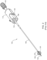
- Figs. 1-2 illustrate an embodiment of a pulmonary tissue modification system 100 used in treatment of a body lumen or passageway in a patient P.
- the system 100 includes a therapeutic energy delivery catheter 102 connectable to a generator 104.
- the catheter 102 has an elongate shaft 106 with at least one energy delivery body 108 near its distal end and a handle 110 at its proximal end. Connection of the catheter 102 to the generator 104 provides electrical energy to the energy delivery body 108, among other features.
- the catheter 102 is insertable into bronchial passageways of a patient P by a variety of methods, such as through a lumen in a bronchoscope 112, as illustrated in Fig. 1 .
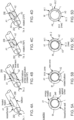
- Fig. 2 provides a closer view of the embodiment of the therapeutic energy delivery catheter 102 of Fig. 1 .
- the energy delivery body 108 includes a single monopolar delivery electrode.
- the energy delivery body 108 includes a plurality of wires or ribbons 120, constrained by a proximal end constraint 122 and a distal end constraint 124, and forms a spiral-shaped basket serving as an electrode.
- the wires or ribbons are straight instead of formed into a spiral-shape (i.e., configured to form a straight-shaped basket).
- the energy delivery body 108 is laser cut from a tube.
- the energy delivery body 108 is self-expandable and delivered to a targeted area in a collapsed configuration.
- This collapsed configuration can be achieved, for example, by placing a sheath 126 over the energy delivery body 108.
- the catheter shaft 106 (within the sheath 126) terminates at the proximal end constraint 122, leaving the distal end constraint 124 essentially unconstrained and free to move relative to the shaft 106 of the catheter 102.
- Advancing the sheath 126 over the energy delivery body 108 allows the distal end constraint 124 to move forward, thereby lengthening/collapsing and constraining the energy delivery body 108.
- the catheter 102 includes a handle 110 at its proximal end.
- the handle 110 is removable, such as by pressing a handle removal button 130.
- the handle 110 includes an energy delivery body manipulation knob 132 wherein movement of the knob 132 causes expansion or retraction/collapse of the basket-shaped electrode.
- the handle 110 also includes a bronchoscope working port snap 134 for connection with the bronchoscope 112 and a cable plug-in port 136 for connection with the generator 104.
- the therapeutic energy delivery catheter 102 is connectable with the generator 104 along with a dispersive (return) electrode 140 applied externally to the skin of the patient P.
- monopolar energy delivery is achieved by supplying energy between the energy delivery body 108 disposed near the distal end of the catheter 102 and the return electrode 140.
- bipolar energy delivery and other arrangements may alternatively be used.
- the therapeutic energy delivery catheter 102 may differ in overall design, such as to include a plurality of energy delivery bodies 108, or may appear similar in overall design, such as to include a single energy delivery body 108 which is configured to function in a bipolar manner.
- bipolar energy delivery allows for the use of a lower voltage to achieve the treatment effect, as compared to monopolar energy delivery.
- the positive and negative poles are close enough together to provide a treatment effect both at the electrode poles and in-between the electrode poles. This can spread the treatment effect over a larger surface area thus requiring a lower voltage to achieve the treatment effect, compare to monopolar.
- this lower voltage may be used to reduce the depth of penetration.
- lower voltage requirements may obviate the use of cardiac synchronization if the delivered voltage is low enough to avoid stimulation of the cardiac muscle cells.
- the generator 104 of Fig. 1 includes a user interface 150, one or more energy delivery algorithms 152, a processor 154, a data storage/retrieval unit 156 (such as a memory and/or database), and an energy-storage sub-system 158 which generates and stores the energy to be delivered.
- a data storage/retrieval unit 156 such as a memory and/or database
- an energy-storage sub-system 158 which generates and stores the energy to be delivered.
- one or more capacitors are used for energy storage/delivery, however any other suitable energy storage element may be used.
- one or more communication ports are included.
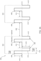
- the generator 104 includes three sub-systems: 1) a high-energy storage system, 2) a high-voltage, medium-frequency switching amplifier, and 3) the system controller, firmware, and user interface.
- the system controller includes a cardiac synchronization trigger monitor that allows for synchronizing the pulsed energy output to the patient's cardiac rhythm.
- the generator takes in alternating current (AC) mains to power multiple direct current (DC) power supplies.
- the generator's controller can cause the DC power supplies to charge a high-energy capacitor storage bank before energy delivery is initiated.
- the generator's controller, high-energy storage banks and a bi-phasic pulse amplifier can operate simultaneously to create a high-voltage, medium frequency output.
- generator electrical architectures may be employed to execute the energy delivery algorithms.
- advanced switching systems are used which are capable of directing the pulsed electric field circuit to the energy delivering electrodes separately from the same energy storage and high voltage delivery system.
- generators employed in advanced energy delivery algorithms employing rapidly varying pulse parameters (e.g., voltage, frequency, etc.) or multiple energy delivery electrodes may utilize modular energy storage and/or high voltage systems, facilitating highly customizable waveform and geographical pulse delivery paradigms.
- the electrical architecture described herein above is for example only, and systems delivering pulsed electric fields may or may not include additional switching amplifier components.
- the user interface 150 can include a touch screen and/or more traditional buttons to allow for the operator to enter patient data, select a treatment algorithm (e.g., energy delivery algorithm 152), initiate energy delivery, view records stored on the storage/retrieval unit 156, and/or otherwise communicate with the generator 104.
- a treatment algorithm e.g., energy delivery algorithm 152
- initiate energy delivery view records stored on the storage/retrieval unit 156
- otherwise communicate with the generator 104 e.g., energy delivery algorithm 152
- the user interface 150 is configured to receive operator-defined inputs.
- the operator-defined inputs can include a duration of energy delivery, one or more other timing aspects of the energy delivery pulse, power, and/or mode of operation, or a combination thereof.
- Example modes of operation can include (but are not limited to): system initiation and self-test, operator input, algorithm selection, pre-treatment system status and feedback, energy delivery, post energy delivery display or feedback, treatment data review and/or download, software update, or any combination or subcombination thereof.
- the system 100 also includes a mechanism for acquiring an electrocardiogram (ECG), such as an external cardiac monitor 170.
- ECG electrocardiogram
- Example cardiac monitors are available from AccuSync Medical Research Corporation.
- the external cardiac monitor 170 is operatively connected to the generator 104.
- the cardiac monitor 170 can be used to continuously acquire an ECG signal.
- External electrodes 172 may be applied to the patient P to acquire the ECG.
- the generator 104 analyzes one or more cardiac cycles and identifies the beginning of a time period during which it is safe to apply energy to the patient P, thus providing the ability to synchronize energy delivery with the cardiac cycle.
- this time period is within milliseconds of the R wave (of the ECG QRS complex) to avoid induction of an arrhythmia, which could occur if the energy pulse is delivered on a T wave. It will be appreciated that such cardiac synchronization is typically utilized when using monopolar energy delivery, however it may be utilized as part of other energy delivery methods.
- the processor 154 modifies and/or switches between the energy-delivery algorithms, monitors the energy delivery and any sensor data, and reacts to monitored data via a feedback loop.
- the processor 154 is configured to execute one or more algorithms for running a feedback control loop based on one or more measured system parameters (e.g., current), one or more measured tissue parameters (e.g., impedance), and/or a combination thereof.
- the data storage/retrieval unit 156 stores data related to the treatments delivered and can optionally be downloaded by connecting a device (e.g., a laptop or thumb drive) to a communication port.
- the device has local software used to direct the download of information, such as, for example, instructions stored on the data storage/retrieval unit 156 and executable by the processor 154.
- the user interface 150 allows for the operator to select to download data to a device and/or system such as, but not limited to, a computer device, a tablet, a mobile device, a server, a workstation, a cloud computing apparatus/system, and/or the like.
- the communication ports which can permit wired and/or wireless connectivity, can allow for data download, as just described but also for data upload such as uploading a custom algorithm or providing a software update.
- the catheter 102 includes one or more sensors 160 that can be used to determine temperature, impedance, resistance, capacitance, conductivity, permittivity, and/or conductance, to name a few. Sensor data can be used to plan the therapy, monitor the therapy and/or provide direct feedback via the processor 154, which can then alter the energy-delivery algorithm 152. For example, impedance measurements can be used to determine not only the initial dose to be applied but can also be used to determine the need for further treatment, or not.
- system 100 can include an automated treatment delivery algorithm that could dynamically respond and adjust and/or terminate treatment in response to inputs such as temperature, impedance at various voltages or AC frequencies, treatment duration or other timing aspects of the energy delivery pulse, treatment power and/or system status.
- imaging is achieved with the use of a commercially-available system, such as a bronchoscope 112 connected with a separate imaging screen 180, as illustrated in Fig. 1 .
- a commercially-available system such as a bronchoscope 112 connected with a separate imaging screen 180, as illustrated in Fig. 1 .
- imaging modalities can be incorporated into the catheter 102 or used alongside or in conjunction with the catheter 102.
- the imaging modality can be mechanically, operatively, and/or communicatively coupled to the catheter 102 using any suitable mechanism.
- one or more energy delivery algorithms 152 are programmable, or can be pre-programmed, into the generator 104 for delivery to the patient P.
- the one or more energy delivery algorithms 152 specify electric signals which provide energy delivered to the airway walls W which are non-thermal (e.g. below a threshold for thermal ablation; below a threshold for inducing coagulative thermal damage), reducing or avoiding inflammation, and preventing denaturation of stromal proteins.
- the algorithm 152 is tailored to affect tissue to a pre-determined depth and/or to target specific types of cellular responses to the energy delivered.
- depth and/or targeting may be affected by parameters of the energy signal prescribed by the one or more energy delivery algorithms 152, the design of the catheter 102 (particularly the one or more energy delivery bodies 108), and/or the choice of monopolar or bipolar energy delivery.
- depths of up to 0.01mm, up to 0.02mm, 0.01-0.02mm, up to 0.03mm, 0.03-0.05mm, up to 0.05mm, up to 0.08mm, up to 0.09mm, up to 0.1mm, up to 0.2mm, up to 0.5mm, up to 0.7mm, up to 1.0mm, up to 1.5mm, up to 2.0mm, or up to 2.3mm or less than 2.3mm can be targeted, particularly when treating a lining of an airway or lung passageway.
- the targeted pre-determined depth is 0.5mm, such as when targeting airway epithelium and submucosal glands, with significant margin of safety to prevent any morbidity-associated cartilage effects at depths of 2.3mm.
- the targeted effect depth is more assertive to treat all of the airway epithelial cells and submucosal glands to a depth of up to 1.36mm, while still preventing safety-associated effects to cartilage at depths of 2.3mm.
- the algorithm 152 is tailored to affect tissue to deeper pre-determined depths such as up to 0.1cm, up to 0.2cm, up to 0.3cm, up to 0.5cm, up to 0.8cm, up to 0.9cm, up to 1cm or 0.5cm to 1cm. In yet other embodiments, such as when applying such treatment to clinical applications involving even deeper targets, the algorithm 152 is tailored to affect tissue to even deeper pre-determined depths such as of up to 2cm or up to 2.5cm
- bipolar energy delivery allows for the use of a lower voltage to achieve the treatment effect, as compared to monopolar energy delivery.
- the positive and negative poles are close enough together to provide a treatment effect both at the electrode poles and in-between the electrode poles. This can concentrate the treatment effect over a specific tissue area thus involving a lower voltage to achieve the treatment effect compared to monopolar.
- this focal capability using lower voltages may be used to reduce the depth of penetration, such as to affect the epithelial cells rather than the submucosal cells. In other instances, this reduced effect penetration depth may be used to focus the energy such as to target epithelial and submucosal layers, while sparing the deeper cartilage tissue.
- lower voltage requirements may obviate the use of cardiac synchronization if the delivered voltage is low enough to avoid stimulation of the cardiac muscle cells.
- the algorithm 152 prescribes a signal having a waveform comprising a series of energy packets wherein each energy packet comprises a series of high voltage pulses.
- the algorithm 152 specifies parameters of the signal such as energy amplitude (e.g., voltage) and duration of applied energy, which is comprised of the number of packets, number of pulses within a packet, and the fundamental frequency of the pulse sequence, to name a few. Additional parameters may include switch time between polarities in biphasic pulses, dead time between biphasic cycles, and rest time between packets, which will be described in more detail in later sections.
- packets may be gated to the cardiac cycle and are thus variable with the patient's heart rate.
- a feedback loop based on sensor information and an auto-shutoff specification, and/or the like, may be included.
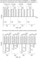
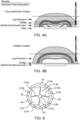
- Fig. 3A illustrates an embodiment of a waveform 400 of a signal prescribed by an energy delivery algorithm 152.
- a first packet 402 and a second packet 404 wherein the packets 402, 404 are separated by a rest period 406.
- each packet 402, 404 is comprised of a first biphasic cycle (comprising a first positive pulse peak 408 and a first negative pulse peak 410) and a second biphasic cycle (comprising a second positive pulse peak 408' and a second negative pulse peak 410').
- the first and second biphasic pulses are separated by dead time 412 (i.e., a pause) between each pulse.
- the biphasic pulses are symmetric so that the set voltage 416 is the same for the positive and negative peaks.
- the biphasic, symmetric waves are also square waves such that the magnitude and time of the positive voltage wave is approximately equal to the magnitude and time of the negative voltage wave.
- portions of the airway wall W cells facing the negative voltage wave undergo cellular depolarization in these regions, where a normally negatively charged cell membrane region briefly turns positive.
- portions of the airway wall W cells facing the positive voltage wave undergo hyperpolarization in which the cell membrane region's electric potential becomes extremely negative. It may be appreciated that in each positive or negative phase of the biphasic pulse, portions of the airway wall W cells will experience the opposite effects. For example, portions of cell membranes facing the negative voltage will experience depolarization, while the portions 180° to this portion will experience hyperpolarization.
- the hyperpolarized portion faces the dispersive or return electrode 140.
- each high voltage pulse or the set voltage 416 is between about 500 V to 10,000 V, particularly about 500 V to 5000 V, about 500 V to 4000 V, about 1000 V to 4000 V, about 2500 V to 4000V, about 2000 to 3500, about 2000 V to 2500V, about 2500 V to 3500 V, including all values and subranges in between including about 500 V, 1000 V, 1500 V, 2000 V, 2500 V, 3000 V, 3500 V, 4000 V.
- each high voltage pulse is in range of approximately 1000 V to 2500 V which can penetrate the airway wall W in particular parameter combinations so as to treat or affect particular cells somewhat shallowly, such as epithelial cells. In some embodiments, each high voltage pulse is in the range of approximately 2500 V to 4000 V which can penetrate the airway W in particular parameter combinations so as to treat or affect particular cells somewhat deeply positioned, such as submucosal cells or smooth muscle cells.
- the set voltage 416 may vary depending on whether the energy is delivered in a monopolar or bipolar fashion. In bipolar delivery, a lower voltage may be used due to the smaller, more directed electric field.
- the energy is delivered in a bipolar fashion and each pulse is in the range of approximately 100 V to 1900 V, particularly 100 V to 999 V, more particularly approximately 500 V to 800 V, such as 500 V, 550 V, 600 V, 650 V, 700 V, 750 V, 800 V. In other embodiments, the energy is delivered in a bipolar fashion and each pulse is between approximately 50 and 5000 volts, including 250 to 1500 volts.
- the targeted voltage-to-distance ratio is 3000 V/cm to evoke the desired clinical effect at the appropriate tissue depth (1.3mm)
- the separation distance is changed from 1mm to 1.2mm, this would result in a necessary increase in treatment voltage from 300 to about 360 V, a change of 20%.
- the number of biphasic cycles per second of time is the frequency.
- biphasic pulses are utilized to reduce undesired muscle stimulation, particularly cardiac muscle stimulation.
- the pulse waveform is monophasic, and there is no clear inherent frequency, and instead a fundamental frequency may be considered by doubling the monophasic pulse length to derive the frequency.
- the signal has a frequency in the range 100kHz-1MHz, more particularly 100kHz - 1000kHz. In some embodiments, the signal has a frequency in the range of approximately 100-600 kHz which typically penetrates the airway W so as to treat or affect particular cells somewhat deeply positioned, such as submucosal cells or smooth muscle cells.
- the signal has a frequency in range of approximately 600kHz -1000kHz or 600 kHz - 1 MHz which typically penetrates the airway wall W so as to treat or affect particular cells somewhat shallowly, such as epithelial cells. It may be appreciated that at some voltages, frequencies at or below 300 kHz may cause undesired muscle stimulation. Therefore, in some embodiments, the signal has a frequency in the range of 400 - 800 kHz or 500-800 kHz, such as 500 kHz, 550 kHz, 600 kHz, 650 kHz, 700 kHz, 750 kHz, 800 kHz. In particular, in some embodiments, the signal has a frequency of 600 kHz. In addition, cardiac synchronization is typically utilized to reduce or avoid undesired cardiac muscle stimulation during sensitive rhythm periods. It may be appreciated that even higher frequencies may be used with components which minimize signal artifacts.
- the frequency of the waveform delivered may vary relative to the treatment voltage in synchrony to retain adequate treatment effect.
- Such synergistic changes would include the decrease in frequency, which evokes a stronger effect, combined with a decrease in voltage, which evokes a weaker effect.
- the treatment may be delivered using 3000 V in a monopolar fashion with a waveform frequency of 800kHz, while in other cases the treatment may be delivered using 2000 V with a waveform frequency of 400 kHz.
- the treatment parameters When used in opposing directions, the treatment parameters may be manipulated in a way that makes it too effective, which may increase muscle contraction likelihood or risk effects to undesirable tissues, such as cartilage for airway treatments. For instance, if the frequency is increased and the voltage is decreased, such as the use of 2000 V at 800 kHz, the treatment may not have sufficient clinical therapeutic benefit. Opposingly, if the voltage was increased to 3000 V and frequency decreased to 400 kHz, there may be undesirable treatment effect extent to cartilage tissues or other collateral sensitive tissues. In some cases, the over-treatment of these undesired tissues could result in morbidity or safety concerns for the patient.
- the algorithm 152 prescribes a signal having a waveform comprising a series of energy packets wherein each energy packet comprises a series of high voltage pulses.
- the cycle count 420 is half the number of pulses within each biphasic packet.
- the first packet 402 has a cycle count 420 of two (i.e. four biphasic pulses).
- the cycle count 420 is set between 1 and 100 per packet, including all values and subranges in between.
- the cycle count 420 is up to 5 pulses, up to 10 pulses, up to 25 pulses, up to 40 pulses, up to 60 pulses, up to 80 pulses, up to 100 pulses, up to 1,000 pulses or up to 2,000 pulses, including all values and subranges in between.
- the packet duration is determined by the cycle count. The higher the cycle count, the longer the packet duration and the larger the quantity of energy delivered.
- packet durations are in the range of approximately 50 to 100 microseconds, such as 50 ⁇ s, 60 ⁇ s, 70 ⁇ s, 80 ⁇ s, 90 ⁇ s or 100 ⁇ s. In other embodiments, the packet durations are in the range of approximately 100 to 1000 microseconds, such as 150 ⁇ s, 200 ⁇ s, 250 ⁇ s, 500 ⁇ s, or 1000 ⁇ s.
- the number of packets delivered during treatment, or packet count may include 1 packet, 2 packets, 3 packets, 4 packets, 5 packets, 10 packets, 15 packets, 20 packets, 50 packets, 100 packets, 1,000 packets, up to 5 packets, up to 10 packets, up to 15 packets, up to 20 packets, up to 100 packets, or up to 1000 packets, including all values and subranges in between.
- 5 packets are delivered, wherein each packet has a packet duration of 100 microseconds and a set voltage of 2500 V.
- 5 to 10 packets are delivered, wherein each packet has a packet duration of 100 microseconds and a set voltage of 2500 V, which results in a treatment effect that has increased intensity and uniformity.
- a total energy-delivery duration between 0.5 to 100 milliseconds at a set voltage of 2500 V can be optimal for the treatment effect.
- the time between packets is set between about 0.1 seconds and about 5 seconds, including all values and subranges in between. In other embodiments, the rest period 406 ranges from about 0.001 seconds to about 10 seconds, including all values and subranges in between. In some embodiments, the rest period 406 is approximately 1 second.
- the signal is synced with the cardiac rhythm so that each packet is delivered synchronously within a designated period relative to the heartbeats, thus the rest periods coincide with the heartbeats. In other embodiments wherein cardiac synchronization is utilized, the rest period 406 may vary, as the rest period between the packets can be influenced by cardiac synchronization, as will be described in later sections.
- a switch time is a delay or period of no energy that is delivered between the positive and negative peaks of a biphasic pulse, as illustrated in Figs. 3B-3C.
- Fig. 3B illustrates various examples of biphasic pulses (comprising a positive peak 408 and a negative peak 410) having a switch time 403 therebetween (however when the switch time 403 is zero, it does not appear).
- the switch time ranges between about 0 to about 1 microsecond, including all values and subranges in between. In other embodiments, the switch time ranges between 1 and 20 microseconds, including all values and subranges in between.
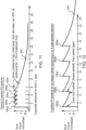
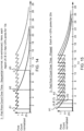
- Fig. 3C illustrates the relationship between effective electric field threshold and switch time.
- Dead time occurs within a packet, but between biphasic pulses. This is in contrast to rest periods which occur between packets.
- the dead time 412 is set between about 0 and about 500 nanoseconds, including 0 to 20 microseconds, including all values and subranges in between.
- the dead time 412 is in a range of approximately 0 to 10 microseconds, or about 0 to about 100 microseconds, or about 0 to about 100 milliseconds, including all values and subranges in between.
- the dead time 412 is in the range of 0.2 to 0.3 microseconds. Dead time may also be used to define a period between separate, monophasic, pulses within a packet.
- Biphasic cancellation or bipolar cancellation is a term used to refer to the reduced induction of cellular modulation in response to biphasic waveforms versus monophasic waveforms, particularly when switch times and dead times are small, such as below 10 ⁇ s.
- switch times and dead times are small, such as below 10 ⁇ s.
- One explanation for this phenomenon is provided here, though it may be appreciated that there are likely other biological, physical, or electrical characteristics or alterations that result in the reduced modulation from biphasic waveforms.
- the influence of biphasic cancellation is reduced by introducing switch time delays and dead time.
- the switch time and dead time are both increased together to strengthen the effect.
- only switch time or only dead time are increased to induce this effect.
- the switch time and the dead time are both set to at least 5 ⁇ s to eliminate biphasic cancellation.
- the reduction in biphasic cancellation may not require complete cell relaxation prior to reversing the polarity, and thus the switch time and the dead time are both set at 0.5 ⁇ s to 2 ⁇ s.
- the switch time and the dead time are set to be the same length as the individual pulse lengths, since further increases in these delays may only offer diminishing returns in terms of increased treatment effect and the collateral increase in muscle contraction.
- the combination of longer-scale pulse durations (>500ns) and stacked pulse cycles with substantial switch time and dead time delays it is possible to use biphasic waveforms without the considerably reduced treatment effect that occurs due to biphasic cancellation.
- the switch time duration is adjusted such that the degree of therapy effect relative to distant cell effects is optimized for the target of the therapy. In some embodiments, the switch time duration is minimized to decrease distant muscle cell contractions, with lesser local therapy effect. In other embodiments, the switch time duration is extended to increase the local therapy effect, with potential additional distant muscle cell contractions. In some embodiments, the switch time or dead time duration are extended to increase the local therapy effect, and the use of neuromuscular paralytics are employed to control the resulting increase in muscle contraction. In some embodiments, switch time duration is 10ns to 2 ⁇ s, while in other embodiments, the switch time duration is 2 ⁇ s to 20 ⁇ s.
- the switch time and dead time delays are minimized to less than 0.1 ⁇ s or to 0 ⁇ s. This elimination of delays minimizes the peripheral, non-targeted treatment effects such as skeletal muscle contraction or cardiac muscle action potential and contraction but will not alter the treatment effect intensity at the targeted site.
- Fig. 3A illustrates an embodiment of a waveform 400 having symmetric pulses such that the voltage and duration of pulse in one direction (i.e., positive or negative) is equal to the voltage and duration of pulse in the other direction.
- Fig. 3D illustrates an example waveform 400 prescribed by another energy delivery algorithm 152 wherein the waveform 400 has voltage imbalance.
- two packets are shown, a first packet 402 and a second packet 404, wherein the packets 402, 404 are separated by a rest period 406.
- each packet 402, 404 is comprised of a first biphasic cycle (comprising a first positive pulse peak 408 having a first voltage V1 and a first negative pulse peak 410 having a second voltage V2) and a second biphasic cycle (comprising a second positive pulse peak 408' having first voltage V1 and a second negative pulse peak 410' having a second voltage V2).
- first voltage V1 is greater than the second voltage V2.
- the first and second biphasic cycles are separated by dead time 412 between each pulse.
- the voltage in one direction i.e., positive or negative
- the voltage in the other direction so that the area under the positive portion of the curve does not equal the area under the negative portion of the curve.
- the first positive peak 408 has a set voltage 416 (V1) that is larger than the set voltage 416' (V2) of the first negative peak 410.
- Fig. 3E illustrates further examples of waveforms having unequal voltages.
- the first packet 402 is comprised of pulses having unequal voltages but equal pulse widths, along with no switch times and dead times.
- the first packet 402 is comprised of four biphasic pulses, each comprising a positive peak 408 having a first voltage V1 and a negative peak 410 having a second voltage V2).
- the first voltage V1 is greater than the second voltage V2.
- the second packet 404 is comprised of pulses having unequal voltages but symmetric pulse widths (as in the first pulse 402), with switch times equal to dead times.
- the third packet 405 is comprised of pulses having unequal voltages but symmetric pulse widths (as in the first pulse 402), with switch times that are shorter than dead times.
- the fourth packet 407 is comprised of pulses having unequal voltages but symmetric pulse widths (as in the first pulse 402), with switch times that are greater than dead times.
- the positive and negative phases of biphasic waveform are not identical, but are balanced, where the voltage in one direction (i.e., positive or negative), is greater than the voltage in the other direction but the length of the pulse is calculated such that the area under the curve of the positive phase equals the area under the curve of the negative phase.
- imbalance includes pulses having pulse widths of unequal duration.
- the biphasic waveform is unbalanced, such that the voltage in one direction is equal to the voltage in the other direction, but the duration of one direction (i.e., positive or negative) is greater than the duration of the other direction, so that the area under the curve of the positive portion of the waveform does not equal the area under the negative portion of the waveform.
- Fig. 3F illustrates further examples of waveforms having unequal pulse widths.
- the first packet 402 is comprised of pulses having equal voltages but unequal pulse widths, along with no switch times and dead times.
- the first packet 402 is comprised of four biphasic pulses, each comprising a positive peak 408 having a first pulse width PW1 and a negative peak 410 having a second pulse width PW2).
- the first pulse width PW1 is greater than the second pulse width PW2.
- the second packet 404 is comprised of pulses having equal voltages but unequal pulse widths (as in the first pulse 402), with switch times equal to dead times.
- the third packet 405 is comprised of pulses having equal voltages but unequal pulse widths (as in the first pulse 402), with switch times that are shorter than dead times.
- the fourth packet 407 is comprised of pulses having equal voltages but unequal pulse widths (as in the first pulse 402), with switch times that are greater than dead times.
- Fig. 3G illustrates an example waveform 400 prescribed by another energy delivery algorithm 152 wherein the waveform is monophasic, a special case of imbalance whereby there is only a positive or only a negative portion of the waveform.
- a first packet 402 and a second packet 404 wherein the packets 402, 404 are separated by a rest period 406.
- each packet 402, 404 is comprised of a first monophasic pulse 430 and a second monophasic pulse 432.
- the first and second monophasic pulses 430, 432 are separated by dead time 412 between each pulse.
- This monophasic waveform could lead to a more desirable treatment effect as the same charge cell membrane potential is maintain for longer durations. However, adjacent muscle groups will be more stimulated by the monophasic waveform, compared to a biphasic waveform.
- Fig. 3H illustrates further examples of waveforms having monophasic pulses.
- the first packet 402 is comprised of pulses having identical voltages and pulse widths, with no switch times (because the pulses are monophasic) and a dead time equal to the active time. In some cases, there may be less dead time duration than the active time of a given pulse.
- the first packet 402 is comprised of three monophasic pulses 430, each comprising a positive peak.
- the waveform may be considered unbalanced with a fundamental frequency representing a cycle period of 2x the active time and no dead time.
- the second packet 404 is comprised of monophasic pulses 430 having equal voltages and pulse widths (as in the first packet 402), with larger dead times.
- the third packet 405 is comprised of monophasic pulses 430 having equal voltages and pulse widths (as in the first packet 402), and even larger dead times.
- the fourth packet 407 is comprised of monophasic pulses 430 having equal voltages and pulse widths (as in the first packet 402), with yet larger dead times.
- an unbalanced waveform is achieved by delivering more than one pulse in one polarity before reversing to an unequal number of pulses in the opposite polarity.
- Fig. 3I illustrates further examples of waveforms having such phase imbalances.
- the first packet 402 is comprised of four cycles having equal voltages and pulse widths, however, opposite polarity pulses are intermixed with monophasic pulses.
- the first cycle comprises a positive peak 408 and a negative peak 410.
- the second cycle is monophasic, comprising a single positive pulse with no subsequent negative pulse 430. This then repeats.
- the second packet 404 is comprised of intermixed biphasic and monophasic cycles (as in the first packet 402), however the pulses have unequal voltages.
- the third packet 405 is comprised of intermixed biphasic and monophasic cycles (as in the first packet 402), however the pulses have unequal pulse widths.
- the fourth packet 407 is comprised of intermixed biphasic and monophasic pulses (as in the first packet 402), however the pulses have unequal voltages and unequal pulse widths. Thus, multiple combinations and permutations are possible.
- TMP negative resting electric transmembrane potential
- changes to the native TMP on the side of the cell that promote a negative TMP will have an exaggerated absolute TMP.
- the side of the cells that induce a positive TMP will have a lower reached absolute TMP induced.
- invocation of the desired therapeutic result may be reached by disturbing the native cell TMP, altering the cell behavior regardless of the final absolute TMP. Further, this difference may vary when considering the TMPs induced on the intracellular organelles.
- the unbalanced TMP manipulation achieved reduces the implications of biphasic cancellation.
- approaching more unbalanced waveforms will enable stronger treatment effects at the same voltage and frequency (if applicable) for biphasic waveforms than those produced from purely balanced biphasic waveforms.
- the treatment effect evoked by a 830ns-415ns-830ns-etc pulse length sequence within a packet will have the pulse constituting the second half of the cycle being half the duration of the original phase.
- This will restrict the induction of TMP manipulation by the second phase of the cycle, but will also generate less reversed TMP, enabling a stronger effect from the original polarity in the subsequent cycle at the original length.
- the "positive" portion of the waveform may be 2500V, with the "negative" portion being 1500V (2500-1250-2500-etc V), which will induce comparable effects on TMP polarization as that which was described for the pulse duration imbalance.
- the fully unbalanced waveforms would not include any opposite polarity component but may still include brief portions of pulses delivered in just the positive phase.
- An example of this is a packet that contains 830ns of positive polarity, an 830ns pause with no energy delivered, followed by another 830ns of positive polarity, and so forth. The same approach is true whether considering the pulse length imbalance or the voltage imbalance, as the absence of a negative pulse is equivalent to setting either of these parameters to zero for the "negative" portion.
- an ideal voltage imbalance may be 2500-1000-2500-... V, or 2500-2000-2500-...V; or 830-100-830-...ns, or 830-500-830-...ns.
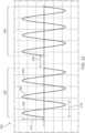
- Fig. 3J illustrates an example waveform 400 prescribed by another energy delivery algorithm 152 wherein the pulses are sinusoidal in shape rather than square.
- the pulses are sinusoidal in shape rather than square.
- two packets are shown, a first packet 402 and a second packet 404, wherein the packets 402, 404 are separated by a rest period 406.
- each packet 402, 404 is comprised three biphasic pulses 440, 442, 444. And, rather than square waves, these pulses 440, 442, 444 are sinusoidal in shape.
- a sinusoidal shape is that it is balanced or symmetrical, whereby each phase is equal in shape. Balancing may assist in reducing undesired muscle stimulation.
- Energy delivery may be actuated by a variety of mechanisms, such as with the use of a button 164 on the catheter 102 or a foot switch 168 operatively connected to the generator 104. Such actuation typically provides a single energy dose.
- the energy dose is defined by the number of packets delivered and the voltage of the packets.
- Each energy dose delivered to the airway wall W maintains the temperature at or in the wall W below a threshold for thermal ablation, particularly thermal ablation of the basement membrane BM which comprises denaturing stromal proteins in the basement membrane or deeper submucosal extracellular protein matrices.
- the doses may be titrated or moderated over time so as to further reduce or eliminate thermal build up during the treatment procedure.
- the energy dose provide energy at a level which induces biological mechanisms and cellular effects which ultimately lead to the regeneration of healthy tissue.
- the tissue modification systems of Figs. 1-2 are adapted for use in the treatment of blood vessels and other cardiac tissue, particularly for the treatment of atrial fibrillation.
- the tissue modification system utilizes energy delivery algorithms configured specifically for cardiac applications, more particularly for affecting tissue in a manner to successfully treat atrial fibrillation.
- Potential cardiac targets for treatment include the regions implicated in generating or conducting aberrant electrical signals. These signals may induce the uncoordinated activation of cardiac myocytes, especially in the atrial regions upstream of the atrioventricular node. Poor operation of the atria reduces their functionality and may result in increased risk for patient angina, stroke, or other cardiac events.
- regions within the pulmonary veins (PVs), particularly the myocardial sleeves of the PVs, are targeted due to the presence of automaticity in cells within the myocardial tissue of the PVs.
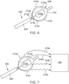
- the therapeutic energy delivery catheter 102 of Fig. 2 is utilized for treating the PVs.
- a modified version of the therapeutic energy delivery catheter 102 of Fig. 2 is utilized for treating the PVs.
- the catheter 102 is modified such that its distal end is curved to approximate an angle of an introducer sheath angle utilized to access PVs.
- the catheter 102 is modified to have a shorter contact length, such as by reducing the length of the electrode body 108.
- the catheter 102 is modified for femoral access.
- femoral access to the PVs involves accessing a femoral vein and advancing the energy body 108 of the catheter 102 into the right atrium via the inferior vena cava and then into the left atrium via a trans-septal puncture.
- This longer pathway is accommodated by modifications to the catheter 102 of Fig. 2 including an increased length of the elongate shaft 206, such as 100 cm or 150 cm, to ensure fit through the trans-septal introducer sheath.
- Additional modifications include assisted deployment of the energy delivery body 108, such as with the use of an internal expansion member (e.g. balloon) to improve the expansion characteristics and likelihood of attaining circumferential treatment contact within the PV.
- Such delivery is typically achieved with the use of ultrasound and angiography to guide physical placement of the energy delivery body 108.
- the catheter 102 and energy delivery algorithms are customized to particularly treat cardiac tissues, as opposed to other luminal targets.
- such customization is particularly aimed at treating atrial fibrillation and includes killing superficial cardiomyocytes that cause aberrant rhythms, or generating a transmural fibrotic tissue restructuring to provide an adequate electrical conduction block.
- the electrodes of the energy delivery body 108 has sufficiently low and focused contact area so as to appropriately concentrate the energy to attain a very concentrated treatment effect that sufficiently penetrates the full thickness of the targeted site, either in the pulmonary veins, their ostia, or the atria.
- the electric voltage delivered is increased relative to other, more superficial, luminal targets, thus increasing the strength of the delivered energy generally while retaining the original electrode contact area.
- secondary pulse parameters are further modified to decrease the lethal electric field threshold of the targeted cell layers (such as by decreasing the biphasic pulsed field frequency, thus increasing the individual pulse length), increasing the number of pulse cycles within a given packet (which increases the total packet duration), or increasing the number of delivered packets.
- the use of asymmetrical (length or voltage) waveforms or monophasic waveforms are employed to significantly strengthen the treatment effect, though the degree of asymmetry or monophasic pulses are balanced to ensure the extent of muscle contraction for the patient remains within acceptable ranges. If necessary, it is also possible to employ the use of a muscle paralytic to further reduce muscle contractions, enabling stronger pulse protocols or asymmetric biphasic or monophasic waveforms.
- the energy delivery body 108 comprises a single monopolar delivery electrode wherein the energy delivery body 108 is comprised of a plurality of wires or ribbons 120 forming a spiral-shaped basket serving as the electrode.
- the energy delivery body 108 is positioned within a PV and pulsed electric fields are delivered via the energy delivery body 108 to the PV so as to induce cell death of the cardiomyocyte and other nominal cell types in the region, which become replaced with fibrous tissue deposition as part of the tissue healing process.
- This fibrous tissue is a poor conduit for electrical conduction, and thus a circumferential, transmural induction of this tissue typically serves as an adequate electrical conduction block, preventing aberrant currents generated in the PV antra from propagating through the atrium. By stopping the aberrant currents, the atrial cardiac muscle cells are able to better coordinate their activation, eliminating fibrillation.
- the catheter 102 is adapted to electrically insulate the portions of the electrode body 108 so as to reduce electric current leakage to the blood. In some embodiments, this involves insulating the proximal and distal portions of the electrode body 108 which have the most contact with blood flowing through the blood vessel. In some embodiments, this significantly reduces electric current leakage to the blood.
- the energy delivery algorithms of the present disclosure are configured to provide improved energy delivery under such conditions (i.e. in the presence of conductive medium).
- such algorithms employ even greater pulse intensities, which are achieved similarly achieving deeper transmural thickness effects, such as increasing the voltage, decreasing the frequency, increasing the number of cycles per packet, or increasing the total number of packets delivered per activation site.
- another approach to overcome the electric current leakage effects is to electrically isolate the contact region of the circumferential electrode body 108 to prevent conduction into the blood which will significantly increase the concentration of energy delivery into the targeted tissue itself, inducing stronger treatment effects.
- an increased depth of penetration may also be desired.
- a relatively shallow depth penetration may be sufficient for adequate energy delivery in the treatment of a disease state.
- a deeper depth penetration may be desired for adequate energy delivery and tissue effect, particularly when treating a condition such as atrial fibrillation.
- PV-LA conduction is gaps within the ablation line and/or failure to produce transmural lesions. Gaps in lines allow resumption of PV-to-LA electrical activity allowing PV triggers to reinitiate atrial fibrillation and may also serve as triggers for other macroreentrant atrial arrhythmias. Likewise, reversible atrial injury may stem from incomplete lesion formation that results in temporary electrical uncoupling but not cell death. Permanent conduction block across linear lesions requires and/or uses transmural lesions involving cell death. As mentioned previously, the specialized catheter designs, distinct energy delivery algorithms, and methods of use of the present disclosure provide increased circumferential regularity of ablation. This reduces conduction gaps within the ablation line.
- transmural lesions can increase the capability of forming transmural lesions. Such improvements can be beneficial in treating atrial fibrillation and may be useful in treating a variety of other conditions and/or other body lumens, include lung passageways, gastrointestinal passageways and other natural and artificial passageways in the body.
- PEFs pulsed electric fields
- PEFs are delivered through independent electrically active electrodes of an energy delivery body, typically in a monopolar fashion. Such delivery concentrates the electrical energy over a smaller surface area, resulting in stronger effects than delivery through an electrode extending circumferentially around the lumen or passageway. It also forces the electrical energy to be delivered in a staged regional approach, mitigating the effect of preferential current pathways through the surrounding tissue. These preferential current pathways are regions with electrical characteristics that induce locally increased electric current flow therethrough rather than through adjacent regions.
- Such pathways typically result in an irregular electric current distribution around the circumference of a targeted lumen, which thus distorts the electric field and causes an irregular increase in treatment effect for some regions and a lower treatment effect in other regions. This may be mitigated or avoided with the use of focal therapy which stabilizes the treatment effect around the circumference of the targeted region.
- focal therapy which stabilizes the treatment effect around the circumference of the targeted region.
- Fig. 4 illustrates an embodiment of a therapeutic energy delivery catheter 202 of the present disclosure configured to provide focal therapy.
- the catheter 202 has an elongate shaft 206 with at least one energy delivery body 208 near its distal end.
- the catheter 202 includes a handle 211 (not shown) at its proximal end, such as a handle similar to handle 110 in Fig. 2 .
- the catheter 202 is connectable to a generator, such as generator 104 of Fig. 1 , which provides electrical energy to the energy delivery body 208, among other features.
- the energy delivery body 208 comprises an expandable member 210, such as an inflatable balloon, having an electrode 212 mounted thereon or incorporated therein.
- the energy delivery body 208 is delivered to a targeted area in a collapsed configuration.
- This collapsed configuration can be achieved, for example, by placing a sheath 226 over the energy delivery body 208, which maintains the collapsed configuration allowing smooth delivery.
- the sheath 226 is retracted or the catheter 202 advanced to allow the energy delivery body 208 to expand.
- the electrode 212 has the form of a pad having a relatively broad surface area and thin cross-section.
- the pad shape provides a broader surface area than other shapes, such as a wire shape.
- the electrode 212 is connected with a conduction wire 214 which electrically connects the electrode 212 with the generator.
- the electrode body 208 has a single electrode 212, however it will be appreciated that the energy delivery body 208 can instead include multiple electrodes 212, such as two, three, four, five, six, seven, eight, nine, ten or more, as will be described in more detail in later sections.
- the electrodes 212 may be comprised of flexible circuit pads or other materials attached to the expandable member 210 or formed into the expandable member 210.
- the electrodes 212 may be distributed radially around the circumference of the expandable member 210 and/or they may be distributed longitudinally along the length of the expandable member 210. Such designs may facilitate improved deployment and retraction qualities, easing user operation and compatibility with standard introducer lumens.
- the catheter 202 is advanced into a body passageway or lumen L, such as over a guidewire, to a target segment along the length of the lumen L.
- the target segment has a length and typically extends circumferentially around the inner surfaces of the walls W of the body lumen L, thus forming a ring.
- it is desired to deliver energy to the circumferential ring in a series of steps, such as illustrated in Figs. 4A-4D with corresponding treatment area outcomes illustrated in Figs. 5A-5D.
- FIG. 4A illustrates a first step wherein the energy delivery body 208 is expanded within the target segment of the body lumen L so that the electrode 212 is positioned adjacent to, against or pressed against a first portion of the wall W of the lumen L. Energy is then delivered to the first portion of the wall W from the electrically connected generator creating a first treatment area A1.
- Fig. 5A provides a cross-sectional illustration of the body lumen L at the target segment showing the first treatment area A1 along the top quarter of the circumferential lumen wall.
- the energy delivery body 208 is then at least partially deflated or retracted and the catheter 202 is rotated, for example 90 degrees in a clockwise direction, as illustrated in Fig. 4B .
- the energy delivery body 208 is then expanded and electrode 212 is positioned adjacent to, against, or pressed against a second portion of the wall W of the lumen L.
- Energy is delivered to the second portion of the wall from the electrically connected generator, creating a second treatment area A2.
- Fig. 5B provides a cross-sectional illustration of the body lumen L at the target segment, showing the second treatment area A2 along the right side quarter of the circumferential lumen wall W.
- the catheter 202 is then rotated again, for example an additional 90 degrees in the clockwise direction, as illustrated in Fig. 4C .
- the electrode 212 is positioned adjacent to, against or pressed against a third portion of the wall of the lumen L.
- FIG. 5C provides a cross-sectional illustration of the body lumen L at the target segment showing the third treatment area A3 along the bottom quarter of the circumferential lumen wall W.
- the catheter 202 is then rotated again, for example an additional 90 degrees in the clockwise direction, as illustrated in Fig. 4D .
- the electrode 212 is positioned adjacent to, against, or pressed against a fourth portion of the wall of the lumen L. Energy is delivered to the fourth portion of the wall from the electrically connected generator, creating a fourth treatment area A4.
- Fig. 5C provides a cross-sectional illustration of the body lumen L at the target segment showing the third treatment area A3 along the bottom quarter of the circumferential lumen wall W.
- the catheter 202 is then rotated again, for example an additional 90 degrees in the clockwise direction, as illustrated in Fig. 4D .
- the electrode 212 is positioned adjacent to, against, or pressed against a fourth portion of the wall of the lumen L. Energy is delivered to the fourth portion of the wall
- 5D provides a cross-sectional illustration of the body lumen L at the target segment, showing the fourth treatment area A4 along the left side quarter of the circumferential lumen wall W.
- the treatment areas A1, A2, A3, A4 collectively cover the circumferential ring around the inner surfaces of the walls W of the body lumen L, thus forming a continuous treatment area without gaps.
- the catheter 202 includes one or more markings along its shaft 206, such as one or more markings around the circumference of the shaft 206, to assist the user in orienting the catheter 202 throughout rotations.
- the one or more markings comprise a plurality of markings spaced apart by a uniform distance, with each marking indicating a number of degrees of rotation. For example, each marking can indicate a rotational distance of 15 degrees.
- particular markings indicate known rotational distances, such as larger markings indicating 90-degree rotations and smaller markings indicating 45-degree rotations.
- particular markings indicate known orientations, such as "top,” and/or particular markings indicate alignment with electrodes 212.
- the markers are disposed along the handle 211 and/or sheath 226.
- the user is able to either rotate both the delivery device (such as a bronchoscope or catheter) and catheter 202, or just rotate the catheter 202 independently.
- Electrode body 208 designs allow circumferential energy delivery to a body lumen L without rotation of the catheter 202.
- An embodiment of such an electrode body 208 is illustrated in Fig. 6 .
- the electrode body 208 includes four electrodes: a first electrode 212a, a second electrode 212b, a third electrode 212c and a fourth electrode 212d.
- the electrodes 212a, 212b, 212c, 212d are disposed around the expandable member 210, equally spaced from each other.
- Each of the electrodes 212a, 212b, 212c, 212d has a corresponding conduction wire 214a 214b, 214c, 214d which provides energy from the generator 104.
- the electrodes 212a, 212b, 212c, 212d are independently energized via their conduction wires 214a 214b, 214c, 214d.
- each electrode 212a, 212b, 212c, 212d forms an electrical pathway to the dispersive (return) electrode 140.
- the first electrode 212a forms a first electrical pathway 216a
- the second electrode 212b forms a second electrical pathway 216b
- the third electrode 212c forms a third electrical pathway 216c
- the fourth electrode 212d forms a fourth electrical pathway 216d.
- the first electrode 212a When, for example, the first electrode 212a is energized and the other electrodes 212b, 212c, 212d are not energized, all of the energy flows along the first electrical pathway 216a to the dispersive electrode 140. This provides a predictable pathway in which any naturally occurring preference in current flow is overcome by the induced current flow through electrical pathway 216a. This increases treatment effect in the tissue area of the lumen wall through which the first electrical pathway 216a flows.
- the tissue layers receive a much more consistent level of energy along the length of the electrode and the drop off in intensity of the electric field occurs at deeper levels. This allows for better transmural effect without increasing the overall voltage or current delivered. In addition, this reduces the likelihood of collateral effects, such as muscle contraction, pain or thermal damage to the area.
- Fig. 9 illustrates a cross-sectional view of a body lumen having walls W, wherein an energy delivery body 208 is positioned therein.
- the expandable member 210 of the energy delivery body 208 is expanded so that the first electrode 212a, second electrode 212b, third electrode 212c and fourth electrode 212d reside against the walls W of the body lumen.
- the electrodes 212a, 212b, 212c, 212d are then energized individually, in a sequence. Energizing first electrode 212a creates first treatment area A1, energizing second electrode 212b creates second treatment area A2, energizing third electrode 212c creates third treatment area A3, and energizing fourth electrode 212d creates fourth treatment area A4.
- the entire ring of wall tissue can be ablated without leaving gaps, and in a more precise and less time-consuming manner than when rotating the catheter 212.
- Focal delivery of energy can be utilized in a variety of ways to improve and/or maximize the effect on the tissue.
- precise timing and sequencing of energy delivery to the electrodes e.g. 212a, 212b, 212c, 212d
- This can be particularly useful in the treatment of atrial fibrillation.
- permanent conduction block across linear lesions uses and/or requires transmural lesions involving cell death rather than temporary reversible effects.
- the PEF waveform is one that employs bipolar cancellation with a frequency that reflects a nanosecond to microsecond pulse duration to mitigate the extent of systemic muscle contraction to acceptably low levels, with or without a paralytic, while retaining its capacity to destabilize both the cell and organelle membranes.
- This induces a multi-modal effect on the cell that uniquely predisposes it to enhanced treatment outcomes beyond those attained with either nanosecond pulsed electric fields (nsPEFs) or traditional millisecond irreversible electroporation (IRE) methods.
- nsPEFs nanosecond pulsed electric fields
- IRE millisecond irreversible electroporation
- the delivered energy can induce sufficiently large and effective treatment zones in the targeted tissues, which is a challenge for nsPEFs, while maintaining an advantageous safety and muscle contraction profile, which is a challenge for traditional millisecond IRE, particularly for monopolar pulse delivery arrangements using an external dispersive pad.
- the electrode circuit has an active portion of the electrode which completes an electrical circuit with a distant secondary electrode
- bipolar or multipolar electric pulse delivery e.g., both the delivery and return of the electric pulse energy is confined within the electrode device itself.
- the electrical energy is more dispersed throughout the body of the patient, which may limit the control of the affected area to some degree when very large lesions are desired. Further, it may result in additional muscle activation, which can be appropriately compensated for by careful pulsed electric field parameter selection to retain a treatment effect without muscle contraction, or by employing the use of a paralytic, which will thus also require general anesthesia for the procedure.
- bipolar and multipolar electrode designs face their own set of advantages and challenges in practical employment of therapeutic pulsed electric field delivery.
- the containment of all active portions of the electrical circuit enable very focused electrical energy delivery, allowing additional aspects of control of electric field distribution, and reducing the likelihood of muscle contraction.
- system impedance can often be very low, and there can be a very high risk of electrical arcing for a given pulse protocol, which reduces the maximum usable pulsed electric field delivered voltage.
- the advanced delivery algorithms 252 decrease the number of PEF exposures to a particular region, concentrating the effects on generating membrane nanoscale defects rather than cumulative injury, wherein cells which are treated are ultimately killed rather than allowed to reverse.
- the membrane can lose its ability to serve as an environmental barrier for the organelle or cell.
- cells should retain homeostasis, by retaining the basic constituents for function and viability within the cell, while preventing or impeding the influx of undesirable quantities or materials from the external environment into the cell.
- diffusion gradients drive materials out of and into the cell against the needs of the cell.
- ATP intracellular adenosine triphosphate
- Fig. 10 is a plot showing an example of pore or defect formation over time in response to PEF energy delivery. It may be appreciated that pore, defect and opening are used interchangeably to describe an inconsistency in a cell or organelle wall, such as potentially leading to loss of homeostasis. As illustrated, pore count rises on a microsecond scale. Pore count then diminishes gradually over time. In this example, using a 4-second pore count half-life, approximately 25% of pores are still open, continuing to damage cell homeostasis, even 8 seconds after PEF application.
- Fig. 11 illustrates pore or defect formation when PEF energy is delivered in intervals that are not optimized for lethality.
- Fig. 11 is a plot showing the effect of delivery of five packets (with rest periods between each packet) on pore count.
- Each of the five energy packet comprises a series of biphasic high voltage pulses.
- five peaks 350a, 350b, 350c, 350d, 350e are illustrated in Fig. 11 , each reaching a maximum value of pore count.
- the pore count decreases over time so that approximately 25% of pores are still open, damaging cell homeostasis, at 13 seconds (indicated by location 352 along the curve).
- each energy packet includes a series of biphasic high voltage pulses.
- peaks 350a, 350b, 350c, 350d, 350e are illustrated, each reaching a maximum value of pore count.
- the rest periods between each packet are such that subsequent PEFs are delivered close enough to maintain disrupted membranes but far enough apart to increase the cumulative amount of cell contents leakage. Consequently, cell damage occurs over a longer period of time.
- pores decrease over time so that approximately 25% of pores are still open, damaging cell homeostasis, at 25 seconds (indicated by location 354 along the curve).
- such extended disruption is achieved by one or more algorithms which cause delivery of PEFs to one or more electrodes in a sequence.
- the sequence of PEFs is applied to the electrodes (e.g. 212a, 212b, 212c, 212d) individually while using monopolar delivery (i.e. each electrode is electrically communicating in sequence with the external dispersive electrode 140).
- one or more algorithms are typically controlled and automated by the generator and eliminate the need for rotation or manipulation of the catheter 202.
- Fig. 13 illustrates a cross-sectional view of a body lumen having walls W wherein an energy delivery body 208 is positioned therein.
- the energy delivery body 208 includes an expandable member 210 having a first electrode 212a, a second electrode 212b and a third electrode 212c which are sized and oriented along the expandable body 210 so as to be positionable and ablate a continuous ring along the inner surface of the walls W of the body lumen.
- each electrode delivers energy to approximately a third of the circumferential lumen wall.
- the electrodes 212a, 212b, 212c are energized individually, in a sequence.
- Energizing first electrode 212a creates first treatment area A1
- energizing second electrode 212b creates second treatment area A2
- energizing third electrode 212c creates third treatment area A3.
- each of the treatment areas receiving electrical energy, but the smaller electrode sizes increases the amount of tissue receiving energy due to boundary effects of the electrodes. Electric current is concentrated at sharp edges and boundaries of electrodes. Therefore, electric fields are stronger at the edges of an electrode than at its center. Therefore, with multiple smaller electrodes, more of the tissue is receiving the depth of the boundary effects rather than the dip in electric field depth that would occur at the center of the electrode. This improves luminal coverage wherein the entire ring of wall tissue is ablated without leaving gaps.
- Figs. 14-15 are plots showing the concepts of Figs. 11-12 as they relate to delivery to multiple electrodes (212a, 212b, 212c) rather than a single electrode.
- Fig. 14 is a plot showing the effects of delivering a plurality of PEFs (five packets) to each electrode 212a, 212b, 212c in a serial manner. It will be appreciated that each energy packet comprises a series of biphasic high voltage pulses. To begin, five packets are delivered to the first electrode 212a while no energy is supplied to the second electrode 212b and third electrode 212c. Then five packets are delivered to the second electrode 212b while no energy is supplied to the first electrode 212a and third electrode 212c.
- Fig. 14 illustrates pore count over time for each treatment area (A1, A2, A3). As shown, each trace decreases over time so that approximately 25% of pores are still open, damaging cell homeostasis, at 13 seconds from the time the first packet was delivered to the corresponding electrode. Thus, Fig. 14 illustrates the concept of Fig. 11 repeated for each treatment area. Thus, although effective in creating a continuous lesion, the PEF energy delivery is not optimized for lethality to cells.
- optimization of lethality may be achieved by delivering a plurality of PEFs (e.g. five packets) to each electrode 212a, 212b, 212c in a serial manner wherein each packet is spaced apart by rest periods that increase and/or maximize the cumulative contributors to cell death.
- PEFs e.g. five packets
- each packet is spaced apart by rest periods that increase and/or maximize the cumulative contributors to cell death.
- alternative sequences are provided which decrease and/or minimize treatment time while maintaining a desired amount and/or optimization of lethality.
- the sequence involves delivering the spaced apart packets in an overlapping pattern to the electrodes 212a, 212b, 212c rather than a serial pattern; the effects of which are illustrated in Fig. 15 .
- the benefits of using a multi-electrode energy delivery body 208 operating in monopolar fashion include:
- maintenance PEFs energy requirements may be further reduced by replacing some of the PEFs in a delivery sequence with maintenance PEFs.
- Maintenance PEFs have a reduced intensity in comparison to regular or primary PEFs.
- the initial generation of membrane defects involves relatively strong transmembrane potentials to be generated in cells exposed to the electric field from PEFs. However, after the effects have been generated, the local region impedance decreases due to improved electric current pathways through (rather than around) the cells. Further, a balance is generally created between cell defects permitting electrolyte mobility across and through the cell, the electric field intensity, and the size, count, and distribution of defect generation.
- the transmembrane potential decreases significantly, as does its dielectric capacity. This means that maintaining the defects for longer periods of time may be permitted by subsequent exposure to electric fields or PEFs at a lower intensity than those required to generate the defects.
- maintenance PEFs may be delivered to the targeted regions in addition to the primary PEFs, which increases effectiveness without significantly increasing energy requirements.
- Fig. 16 is a plot showing a sequence of PEFs comprising primary PEFs and maintenance PEFs therebetween. It will be appreciated that the PEFs may be considered pulses or packets. Referring to Fig. 16 a first primary PEF 400 is shown followed by three maintenance PEFs 402. A second primary PEF 404 then follows, followed by three maintenance PEFs 402, and a third primary PEF 406 then follows, followed by three maintenance PEFs 402, etc. It will be appreciated that any number of maintenance pulses may be used and may form a regular pattern (as shown in Fig. 16 ) or an irregular pattern, such as having differing numbers of maintenance pulses between primary pulses. Likewise, it will be appreciated that the maintenance pulses may have the same or differing intensity throughout the delivery sequence.
- Fig. 17 is a plot showing the effect of a delivery sequence as in Fig. 16 on pore count in a target membrane. As shown, the pore count reaches a maximum level upon receiving the first primary PEF 400. Pore count then declines until receiving a maintenance PEF 402 which then restores the pore count toward the maximum level. This repeats for each maintenance PEF 402 and then for later primary PEFs and follow on maintenance PEFs. It will be appreciated that in some instances the maintenance PEFs are sufficient to restore the pore count (such as "topping off”) so that later primary PEFs are not needed as frequently, or not needed altogether.
Landscapes
- Health & Medical Sciences (AREA)
- Life Sciences & Earth Sciences (AREA)
- Engineering & Computer Science (AREA)
- Surgery (AREA)
- Animal Behavior & Ethology (AREA)
- General Health & Medical Sciences (AREA)
- Biomedical Technology (AREA)
- Heart & Thoracic Surgery (AREA)
- Veterinary Medicine (AREA)
- Public Health (AREA)
- Nuclear Medicine, Radiotherapy & Molecular Imaging (AREA)
- Molecular Biology (AREA)
- Otolaryngology (AREA)
- Medical Informatics (AREA)
- Radiology & Medical Imaging (AREA)
- Cardiology (AREA)
- Physics & Mathematics (AREA)
- Plasma & Fusion (AREA)
- Vascular Medicine (AREA)
- Surgical Instruments (AREA)
- Electrotherapy Devices (AREA)
Claims (15)
- System zur Behandlung eines Durchgangs innerhalb eines Körpers, wobei das System Folgendes umfasst:einen Katheter (202), der mindestens eine erste Elektrode (212a) und mindestens eine zusätzliche Elektrode (212b) umfasst, die in der Nähe seines distalen Endes angeordnet ist, wobei das distale Ende des Katheters (202) dafür konfiguriert ist, innerhalb des Durchgangs positioniert zu werden, so dass die mindestens eine erste Elektrode (212a) und mindestens eine zusätzliche Elektrode (212b) in der Lage sind, gepulste elektrische Feldenergie an eine Innenfläche des Durchgangs zu übertragen; undeinen Generator (140), der in elektrischer Verbindung mit der ersten Elektrode (212a) steht, wobei der Generator (140) mindestens einen Energieabgabealgorithmus enthält, der ein elektrisches Signal an die erste Elektrode (212b) liefert, so dass gepulste elektrische Feldenergie an Zellen auf der Innenfläche des Durchgangs abgegeben wird,wobei das elektrische Signal eine Vielzahl von Paketen umfasst,wobei jedes Paket eine Vielzahl von zweiphasigen Zyklen umfasst undwobei jedes Paket zeitlich um 0,0001 bis 10 Sekunden getrennt ist, undwobei der mindestens eine Energieabgabealgorithmus der ersten Elektrode (212a) und/oder der mindestens einen zusätzlichen Elektrode (212b) zwischen den Paketen gepulste elektrische Erhaltungsfeldenergie bereitstellt, wobei die gepulste elektrische Erhaltungsfeldenergie eine niedrigere Spannung aufweist als die gepulste elektrische Feldenergie.
- System nach Anspruch 1, wobei die gepulste elektrische Feldenergie in einer monopolaren Anordnung geliefert wird.
- System nach Anspruch 1 oder 2, wobei die erste Elektrode (212a) und die mindestens eine zusätzliche Elektrode (212b) so angeordnet sind, dass sie die gepulste elektrische Feldenergie an einen Umfang der Innenfläche des Durchgangs liefern.
- System nach einem der Ansprüche 1 bis 3, wobei der mindestens eine Energieabgabealgorithmus die Vielzahl von Paketen an die erste Elektrode (212a) liefert, bevor eine weitere Vielzahl von Paketen an jede der mindestens einen zusätzlichen Elektrode (212b) geliefert wird.
- System nach Anspruch 3 oder 4, wobei der mindestens eine Energieabgabealgorithmus die weitere Vielzahl von Paketen an jede der mindestens einen zusätzlichen Elektrode (212b) liefert, bevor die Vielzahl von Paketen an die erste Elektrode (212a) geliefert ist.
- System nach einem der vorhergehenden Ansprüche, wobei die gepulste elektrische Erhaltungsfeldenergie eine Spannung von weniger als der Hälfte der gepulsten elektrischen Feldenergie aufweist.
- System nach einem der vorhergehenden Ansprüche, das ferner einen Herzmonitor umfasst, der so konfiguriert ist, dass er ein Herzsignal des Patienten erfasst, und wobei der Generator die gepulste elektrische Erhaltungsfeldenergie synchron mit dem Herzsignal bereitstellt.
- System nach einem der vorhergehenden Ansprüche, wobei die erste Elektrode (212a) und die mindestens eine zusätzliche Elektrode (212b) an einem dehnbaren Element angebracht oder darin eingebettet sind.
- System nach einem der vorhergehenden Ansprüche, wobei die erste Elektrode (212a) und die mindestens eine zusätzliche Elektrode (212b) eine Vielzahl von Drähten oder Bändern umfassen, die einen Elektrodenabgabekörper mit einer dehnbaren Korbform bilden, wobei ein Teil der Korbform isoliert ist.
- System nach einem der vorhergehenden Ansprüche, wobei die gepulste elektrische Feldenergie an Zellen auf der Innenfläche des Durchgangs in einer Weise abgegeben wird, dass die Homöostase der Zellen in einer Tiefe von bis zu 2,5 cm und nicht darüber gestört wird.
- System nach einem der vorhergehenden Ansprüche, wobei die Vielzahl von Paketen die gepulste elektrische Feldenergie für weniger als oder gleich 10.000 Mikrosekunden erzeugt.
- System nach Anspruch 11, wobei die Vielzahl von Paketen die gepulste elektrische Feldenergie für weniger als oder gleich 500 Mikrosekunden erzeugt.
- System nach Anspruch 12, wobei die Vielzahl von Paketen die gepulste elektrische Feldenergie für weniger als oder gleich 5 - 50 Mikrosekunden erzeugt.
- System nach einem der vorhergehenden Ansprüche, wobei die gepulste elektrische Feldenergie aus 40 bis 500 Paketen besteht.
- System nach Anspruch 14, wobei die Vielzahl von Paketen weniger als oder gleich 10 Pakete umfasst.
Priority Applications (1)
| Application Number | Priority Date | Filing Date | Title |
|---|---|---|---|
| EP25166670.7A EP4552592A3 (de) | 2017-12-26 | 2018-12-26 | Optimierung der energieabgabe für verschiedene anwendungen |
Applications Claiming Priority (4)
| Application Number | Priority Date | Filing Date | Title |
|---|---|---|---|
| US201762610430P | 2017-12-26 | 2017-12-26 | |
| US201862693622P | 2018-07-03 | 2018-07-03 | |
| EP18836576.1A EP3731771B1 (de) | 2017-12-26 | 2018-12-26 | Optimierung der energieabgabe für verschiedene anwendungen |
| PCT/US2018/067504 WO2019133608A1 (en) | 2017-12-26 | 2018-12-26 | Optimization of energy delivery for various applications |
Related Parent Applications (2)
| Application Number | Title | Priority Date | Filing Date |
|---|---|---|---|
| EP18836576.1A Division-Into EP3731771B1 (de) | 2017-12-26 | 2018-12-26 | Optimierung der energieabgabe für verschiedene anwendungen |
| EP18836576.1A Division EP3731771B1 (de) | 2017-12-26 | 2018-12-26 | Optimierung der energieabgabe für verschiedene anwendungen |
Related Child Applications (2)
| Application Number | Title | Priority Date | Filing Date |
|---|---|---|---|
| EP25166670.7A Division EP4552592A3 (de) | 2017-12-26 | 2018-12-26 | Optimierung der energieabgabe für verschiedene anwendungen |
| EP25166670.7A Division-Into EP4552592A3 (de) | 2017-12-26 | 2018-12-26 | Optimierung der energieabgabe für verschiedene anwendungen |
Publications (2)
| Publication Number | Publication Date |
|---|---|
| EP4218641A1 EP4218641A1 (de) | 2023-08-02 |
| EP4218641B1 true EP4218641B1 (de) | 2025-05-07 |
Family
ID=65036907
Family Applications (3)
| Application Number | Title | Priority Date | Filing Date |
|---|---|---|---|
| EP23178276.4A Active EP4218641B1 (de) | 2017-12-26 | 2018-12-26 | Optimierung der energieabgabe für verschiedene anwendungen |
| EP25166670.7A Pending EP4552592A3 (de) | 2017-12-26 | 2018-12-26 | Optimierung der energieabgabe für verschiedene anwendungen |
| EP18836576.1A Active EP3731771B1 (de) | 2017-12-26 | 2018-12-26 | Optimierung der energieabgabe für verschiedene anwendungen |
Family Applications After (2)
| Application Number | Title | Priority Date | Filing Date |
|---|---|---|---|
| EP25166670.7A Pending EP4552592A3 (de) | 2017-12-26 | 2018-12-26 | Optimierung der energieabgabe für verschiedene anwendungen |
| EP18836576.1A Active EP3731771B1 (de) | 2017-12-26 | 2018-12-26 | Optimierung der energieabgabe für verschiedene anwendungen |
Country Status (8)
| Country | Link |
|---|---|
| US (4) | US11547851B2 (de) |
| EP (3) | EP4218641B1 (de) |
| JP (3) | JP2021508533A (de) |
| CN (2) | CN118383863A (de) |
| AU (2) | AU2018397478B2 (de) |
| CA (1) | CA3087183A1 (de) |
| DK (2) | DK3731771T3 (de) |
| WO (1) | WO2019133608A1 (de) |
Families Citing this family (95)
| Publication number | Priority date | Publication date | Assignee | Title |
|---|---|---|---|---|
| EP3154463B1 (de) | 2014-06-12 | 2019-03-27 | Farapulse, Inc. | Vorrichtung für schnelle und selektive transurethrale gewebeablation |
| IL300334B1 (en) | 2015-10-07 | 2025-11-01 | Mayo Found Medical Education & Res | Electroporation for obesity or diabetes treatment |
| US10172673B2 (en) | 2016-01-05 | 2019-01-08 | Farapulse, Inc. | Systems devices, and methods for delivery of pulsed electric field ablative energy to endocardial tissue |
| US10660702B2 (en) | 2016-01-05 | 2020-05-26 | Farapulse, Inc. | Systems, devices, and methods for focal ablation |
| US20170189097A1 (en) | 2016-01-05 | 2017-07-06 | Iowa Approach Inc. | Systems, apparatuses and methods for delivery of ablative energy to tissue |
| US12144541B2 (en) | 2016-01-05 | 2024-11-19 | Boston Scientific Scimed, Inc. | Systems, apparatuses and methods for delivery of ablative energy to tissue |
| US10905329B2 (en) | 2016-06-09 | 2021-02-02 | Biosense Webster (Israel) Ltd. | Multi-function conducting elements for a catheter |
| CA3029260A1 (en) | 2016-06-27 | 2018-01-04 | Gala Therapeutics, Inc. | Generator and a catheter with an electrode and a method for treating a lung passageway |
| US12403305B2 (en) | 2016-06-27 | 2025-09-02 | Galvanize Therapeutics, Inc. | Immunostimulation in the treatment of viral infection |
| US9987081B1 (en) | 2017-04-27 | 2018-06-05 | Iowa Approach, Inc. | Systems, devices, and methods for signal generation |
| US12029545B2 (en) | 2017-05-30 | 2024-07-09 | Biosense Webster (Israel) Ltd. | Catheter splines as location sensors |
| JP7586706B2 (ja) | 2017-09-12 | 2024-11-19 | ボストン サイエンティフィック サイムド,インコーポレイテッド | 心室フォーカルアブレーションのためのシステム、装置、及び方法 |
| US12318126B2 (en) | 2021-06-25 | 2025-06-03 | Covidien Lp | Current generator for a medical treatment system |
| US11974752B2 (en) | 2019-12-12 | 2024-05-07 | Covidien Lp | Electrically enhanced retrieval of material from vessel lumens |
| US11058444B2 (en) | 2017-12-11 | 2021-07-13 | Covidien Lp | Electrically enhanced retrieval of material from vessel lumens |
| EP4218641B1 (de) | 2017-12-26 | 2025-05-07 | Galvanize Therapeutics, Inc. | Optimierung der energieabgabe für verschiedene anwendungen |
| EP4275738B1 (de) | 2018-02-08 | 2025-12-17 | Boston Scientific Scimed, Inc. | Vorrichtung zur kontrollierten abgabe von ablationsenergie mit einem gepulsten elektrischen feld an gewebe |
| US20190314083A1 (en) | 2018-04-11 | 2019-10-17 | Biosense Webster (Israel) Ltd. | Flexible Multi-Arm Catheter with Diametrically Opposed Sensing Electrodes |
| CN115836908A (zh) | 2018-05-07 | 2023-03-24 | 波士顿科学医学有限公司 | 用于将消融能量递送到组织的系统、设备和方法 |
| WO2019217317A1 (en) | 2018-05-07 | 2019-11-14 | Farapulse, Inc. | Systems, apparatuses, and methods for filtering high voltage noise induced by pulsed electric field ablation |
| US20240398462A1 (en) * | 2018-06-01 | 2024-12-05 | Aqua Medical, Inc. | Duodenal Ablation with Improved Depth and Consistency of Ablation |
| JP7619937B2 (ja) | 2018-09-20 | 2025-01-22 | ボストン サイエンティフィック サイムド,インコーポレイテッド | 心内膜組織へのパルス電界アブレーションエネルギーの送達のためのシステム、装置、および方法 |
| US11045628B2 (en) | 2018-12-11 | 2021-06-29 | Biosense Webster (Israel) Ltd. | Balloon catheter with high articulation |
| US11207016B2 (en) | 2018-12-28 | 2021-12-28 | Biosense Webster (Israel) Ltd. | Mapping ECG signals using a multipole electrode assembly |
| US11850051B2 (en) | 2019-04-30 | 2023-12-26 | Biosense Webster (Israel) Ltd. | Mapping grid with high density electrode array |
| CA3147592A1 (en) | 2019-07-16 | 2021-01-21 | Galary, Inc. | Treatment of the reproductive tract with pulsed electric fields |
| US11712172B2 (en) | 2019-07-18 | 2023-08-01 | Biosense Webster (Israel) Ltd. | Visual guidance for positioning a distal end of a medical probe |
| US11759150B2 (en) | 2019-08-27 | 2023-09-19 | Biosense Webster (Israel) Ltd. | Accurate basket catheter tracking |
| US10625080B1 (en) | 2019-09-17 | 2020-04-21 | Farapulse, Inc. | Systems, apparatuses, and methods for detecting ectopic electrocardiogram signals during pulsed electric field ablation |
| AU2020371627B2 (en) | 2019-10-21 | 2025-12-11 | Endogenex, Inc. | Devices, systems, and methods for pulsed electric field treatment of the duodenum |
| US11497541B2 (en) | 2019-11-20 | 2022-11-15 | Boston Scientific Scimed, Inc. | Systems, apparatuses, and methods for protecting electronic components from high power noise induced by high voltage pulses |
| US11065047B2 (en) | 2019-11-20 | 2021-07-20 | Farapulse, Inc. | Systems, apparatuses, and methods for protecting electronic components from high power noise induced by high voltage pulses |
| US10842572B1 (en) | 2019-11-25 | 2020-11-24 | Farapulse, Inc. | Methods, systems, and apparatuses for tracking ablation devices and generating lesion lines |
| US20210161582A1 (en) * | 2019-12-03 | 2021-06-03 | St. Jude Medical, Cardiology Division, Inc. | Electroporation system and method |
| US11950930B2 (en) | 2019-12-12 | 2024-04-09 | Biosense Webster (Israel) Ltd. | Multi-dimensional acquisition of bipolar signals from a catheter |
| US11517218B2 (en) | 2019-12-20 | 2022-12-06 | Biosense Webster (Israel) Ltd. | Selective graphical presentation of electrophysiological parameters |
| EP4272674A3 (de) * | 2020-02-28 | 2024-01-10 | St. Jude Medical, Cardiology Division, Inc. | Elektrodenanordnung mit expandierbarem isolationselement |
| WO2021173215A1 (en) | 2020-02-28 | 2021-09-02 | St. Jude Medical, Cardiology Division, Inc. | Electrode assembly including expandable isolation member |
| CN112716599B (zh) * | 2020-02-28 | 2025-01-24 | 圣犹达医疗用品心脏病学部门有限公司 | 包括可膨胀隔离构件的电极组件 |
| WO2021181231A2 (en) * | 2020-03-07 | 2021-09-16 | Arga' Medtech Sa | Ablation equipment for delivering non-thermal energy to treat target regions of tissue in organs and control method thereof |
| WO2021207385A1 (en) * | 2020-04-08 | 2021-10-14 | Galary, Inc. | Pulsed electric field waveform manipulation and use |
| US20210369132A1 (en) | 2020-05-29 | 2021-12-02 | Biosense Webster (Israel) Ltd. | Intraluminal reference electrode for cardiovascular treatment apparatus |
| EP4125663B1 (de) * | 2020-06-03 | 2024-12-25 | St. Jude Medical, Cardiology Division, Inc. | System zur irreversiblen elektroporation |
| US11987017B2 (en) | 2020-06-08 | 2024-05-21 | Biosense Webster (Israel) Ltd. | Features to assist in assembly and testing of devices |
| US12310652B2 (en) | 2020-07-24 | 2025-05-27 | Boston Scientific Scimed, Inc. | Hybrid electroporation ablation catheter |
| EP4185228A1 (de) * | 2020-07-24 | 2023-05-31 | Boston Scientific Scimed Inc. | Anwendung eines elektrischen feldes zur einzelschuss-herzablation durch irreversible elektroporation |
| CN116829691A (zh) | 2020-08-04 | 2023-09-29 | 盖能适治疗股份有限公司 | 分子到体内细胞的脉冲电场转移 |
| US20220047326A1 (en) * | 2020-08-13 | 2022-02-17 | Biosense Webster (Israel) Ltd. | Applying Bipolar Ablation Energy Between Shorted Electrode Groups |
| US12076071B2 (en) | 2020-08-14 | 2024-09-03 | Kardium Inc. | Systems and methods for treating tissue with pulsed field ablation |
| JP7617250B2 (ja) | 2020-09-08 | 2025-01-17 | ボストン サイエンティフィック サイムド,インコーポレイテッド | パルス電界アブレーションのための輪郭成形電極、ならびにそのシステム、デバイス、および方法 |
| US12048479B2 (en) | 2020-09-10 | 2024-07-30 | Biosense Webster (Israel) Ltd. | Surface mounted electrode catheter |
| US11950840B2 (en) | 2020-09-22 | 2024-04-09 | Biosense Webster (Israel) Ltd. | Basket catheter having insulated ablation electrodes |
| US11950841B2 (en) | 2020-09-22 | 2024-04-09 | Biosense Webster (Israel) Ltd. | Basket catheter having insulated ablation electrodes and diagnostic electrodes |
| US12082875B2 (en) | 2020-09-24 | 2024-09-10 | Biosense Webster (Israel) Ltd | Balloon catheter having a coil for sensing tissue temperature and position of the balloon |
| US11974803B2 (en) | 2020-10-12 | 2024-05-07 | Biosense Webster (Israel) Ltd. | Basket catheter with balloon |
| US12201786B2 (en) | 2020-12-17 | 2025-01-21 | Biosense Webster (Israel) Ltd. | Measurement of distal end dimension of catheters using magnetic fields |
| US11918383B2 (en) | 2020-12-21 | 2024-03-05 | Biosense Webster (Israel) Ltd. | Visualizing performance of catheter electrodes |
| WO2022139797A1 (en) * | 2020-12-21 | 2022-06-30 | Arga' Medtech Sa | Electronic apparatus for delivering coherent sine burst irreversible electroporation energy to a biological tissue |
| CN114652426B (zh) * | 2020-12-23 | 2025-06-06 | 上海微创电生理医疗科技股份有限公司 | 脉冲消融设备、系统、控制方法及可读存储介质 |
| EP4284276A1 (de) | 2021-01-27 | 2023-12-06 | Boston Scientific Scimed, Inc. | Spannungsgesteuerte pulssequenzen für irreversible elektroporationsablationen |
| IL307390B2 (en) | 2021-04-07 | 2025-02-01 | Btl Medical Dev A S | Device and method for ablation (burning) by electric pulse field |
| US12446944B2 (en) | 2021-04-26 | 2025-10-21 | Pulse Biosciences, Inc. | Mapping and ablation applicators |
| KR20230161488A (ko) | 2021-04-26 | 2023-11-27 | 펄스 바이오사이언스, 인크. | 원주 방향 절제 장치 및 방법 |
| US12564440B2 (en) | 2021-04-26 | 2026-03-03 | Pulse Biosciences, Inc. | Multi-strut ablation and sensing catheter devices and methods |
| US12064170B2 (en) | 2021-05-13 | 2024-08-20 | Biosense Webster (Israel) Ltd. | Distal assembly for catheter with lumens running along spines |
| JP2024522624A (ja) * | 2021-06-10 | 2024-06-21 | ガルヴァナイズ セラピューティクス,インコーポレイテッド | 脈管の治療におけるパルス化電場の印加 |
| HRP20250794T1 (hr) * | 2021-07-06 | 2025-08-29 | Btl Medical Development A.S. | Uređaj za ablaciju pulsnim poljem |
| CN113729918B (zh) * | 2021-08-12 | 2024-10-18 | 圣犹达医疗用品心脏病学部门有限公司 | 使用不对称波形的电穿孔的系统和方法 |
| US20230052114A1 (en) * | 2021-08-12 | 2023-02-16 | St. Jude Medical, Cardiology Division, Inc. | Systems and methods for electroporation using asymmetric waveforms and waveforms with reduced burst duration |
| US12364426B2 (en) | 2021-08-12 | 2025-07-22 | Biosense Webster (Israel) Ltd. | Electro-anatomical mapping and annotation presented in electrophysiological procedures |
| US11944374B2 (en) * | 2021-08-30 | 2024-04-02 | Covidien Lp | Electrical signals for retrieval of material from vessel lumens |
| US12004804B2 (en) | 2021-09-09 | 2024-06-11 | Biosense Webster (Israel) Ltd. | Basket catheter with mushroom shape distal tip |
| US12478424B2 (en) | 2021-09-10 | 2025-11-25 | Biosense Webster (Israel) Ltd. | Staggered pairs of biased ablation electrodes on basket catheter |
| JP2024534500A (ja) * | 2021-09-20 | 2024-09-20 | ガルヴァナイズ セラピューティクス,インコーポレイテッド | パルス電界療法に対する制御された病変および免疫応答 |
| US12011280B2 (en) | 2021-10-04 | 2024-06-18 | Biosense Webster (Israel) Ltd. | Electrophysiological mapping in the presence of injury current |
| US12533489B2 (en) | 2021-10-08 | 2026-01-27 | Biosense Webster (Israel) Ltd. | Measuring tissue proximity for multi-electrode catheter |
| US12419683B2 (en) | 2021-12-22 | 2025-09-23 | Biosense Webster (Israel) Ltd. | Irreversible electroporation with shorted electrodes |
| CN114271931B (zh) * | 2021-12-23 | 2023-09-12 | 心航路医学科技(广州)有限公司 | 一种脉冲消融系统 |
| CN114259296A (zh) * | 2021-12-23 | 2022-04-01 | 心航路医学科技(广州)有限公司 | 一种脉冲电场发生器 |
| US20230210397A1 (en) * | 2021-12-31 | 2023-07-06 | Rebeccatech Llc | Non-invasive and permeable rf diagnosis and treatment equipment and its catheter |
| US12484961B2 (en) | 2022-01-20 | 2025-12-02 | Biosense Webster (Israel) Ltd. | Mechanical retainer systems for electrodes of a basket catheter, and methods of the same |
| US12440263B2 (en) | 2022-01-20 | 2025-10-14 | Biosense Webster (Israel) Ltd. | Systems and methods for tripodic spines forming a spherical basket for improved tissue contact and current delivery |
| US12446946B2 (en) | 2022-01-20 | 2025-10-21 | Biosense Webster (Israel) Ltd. | Systems and methods for a single spiral electrode assembly forming a spherical basket for improved tissue contact and current delivery |
| CN114534091B (zh) * | 2022-02-17 | 2022-09-09 | 湖南安泰康成生物科技有限公司 | 利用电场抑制肿瘤增殖的设备及其控制装置 |
| US12471989B2 (en) | 2022-04-28 | 2025-11-18 | Biosense Webster (Israel) Ltd. | Strengthened expandable baskets for medical probes and medical probes containing strengthen expandable baskets |
| CN119421667A (zh) * | 2022-04-28 | 2025-02-11 | 盖能适治疗股份有限公司 | 在脉冲电场的使用中的损伤灶优化 |
| CA3257818A1 (en) | 2022-06-10 | 2023-12-14 | Alpfa Medical, Inc. | APPARATUS, SYSTEMS AND METHODS FOR SOFT TISSUE REMOVAL |
| WO2024075034A1 (en) | 2022-10-05 | 2024-04-11 | Btl Medical Technologies S.R.O. | Pulsed field ablation device and method |
| US12533185B2 (en) | 2022-12-28 | 2026-01-27 | Biosense Webster (Israel) Ltd. | Basket end effector with distal position sensor |
| US12521035B2 (en) | 2022-12-29 | 2026-01-13 | Biosense Webster (Israel) Ltd. | Cylindrical cage systems and methods for distributed tissue contact for mapping and ablation |
| US20250186097A1 (en) * | 2023-12-11 | 2025-06-12 | St. Jude Medical, Cardiology Division, Inc. | Systems and methods for pulsed field ablation with increased pulse periods |
| WO2025179046A1 (en) * | 2024-02-22 | 2025-08-28 | St. Jude Medical, Cardiology Division, Inc. | Systems and methods for pulsed field ablation with superimposed waveforms |
| US12484963B2 (en) | 2024-04-03 | 2025-12-02 | Field Medical, Inc. | Systems and methods for affecting a target tissue via a pulsed field |
| US12150702B1 (en) * | 2024-06-03 | 2024-11-26 | Physcade, Inc. | Generator and catheter for tissue ablation |
| CN118830912B (zh) * | 2024-07-02 | 2025-07-22 | 南京康友医疗科技有限公司 | 一种柔性脉冲电场消融导管及其工作方法 |
Family Cites Families (178)
| Publication number | Priority date | Publication date | Assignee | Title |
|---|---|---|---|---|
| US5386837A (en) | 1993-02-01 | 1995-02-07 | Mmtc, Inc. | Method for enhancing delivery of chemotherapy employing high-frequency force fields |
| US5993434A (en) | 1993-04-01 | 1999-11-30 | Genetronics, Inc. | Method of treatment using electroporation mediated delivery of drugs and genes |
| AUPN957296A0 (en) | 1996-04-30 | 1996-05-23 | Cardiac Crc Nominees Pty Limited | A system for simultaneous unipolar multi-electrode ablation |
| SE509241C2 (sv) | 1996-07-18 | 1998-12-21 | Radinvent Ab | Anordningar för elektrodynamisk strålterapi av tumörsjukdomar |
| US5906609A (en) * | 1997-02-05 | 1999-05-25 | Sahar Technologies | Method for delivering energy within continuous outline |
| US6241701B1 (en) | 1997-08-01 | 2001-06-05 | Genetronics, Inc. | Apparatus for electroporation mediated delivery of drugs and genes |
| US6055453A (en) | 1997-08-01 | 2000-04-25 | Genetronics, Inc. | Apparatus for addressing needle array electrodes for electroporation therapy |
| EP1003847A4 (de) | 1997-09-04 | 2005-04-06 | Science Res Lab Inc | Zelltrennung mittels elektrischer felder |
| US6038478A (en) | 1997-10-16 | 2000-03-14 | Huntingdon Medical Research Institutes | Lymphocyte attraction by electrical stimulation |
| WO1999035986A1 (en) | 1998-01-14 | 1999-07-22 | Conway-Stuart Medical, Inc. | Electrosurgical apparatus for treating gastroesophageal reflux disease (gerd) and method |
| JP2002504390A (ja) | 1998-02-27 | 2002-02-12 | キューロン メディカル,インコーポレイテッド | 電気外科的に食道括約筋を処置するための装置 |
| US6107699A (en) * | 1998-05-22 | 2000-08-22 | Scimed Life Systems, Inc. | Power supply for use in electrophysiological apparatus employing high-voltage pulses to render tissue temporarily unresponsive |
| JP3819160B2 (ja) | 1998-09-18 | 2006-09-06 | 富士通株式会社 | 情報管理方法および情報管理装置 |
| US6325797B1 (en) * | 1999-04-05 | 2001-12-04 | Medtronic, Inc. | Ablation catheter and method for isolating a pulmonary vein |
| US6738663B2 (en) | 1999-04-09 | 2004-05-18 | Oncostim, A Minnesota Corporation | Implantable device and method for the electrical treatment of cancer |
| US6366808B1 (en) | 2000-03-13 | 2002-04-02 | Edward A. Schroeppel | Implantable device and method for the electrical treatment of cancer |
| US6326177B1 (en) | 1999-08-04 | 2001-12-04 | Eastern Virginia Medical School Of The Medical College Of Hampton Roads | Method and apparatus for intracellular electro-manipulation |
| US20020010491A1 (en) | 1999-08-04 | 2002-01-24 | Schoenbach Karl H. | Method and apparatus for intracellular electro-manipulation |
| US7113821B1 (en) | 1999-08-25 | 2006-09-26 | Johnson & Johnson Consumer Companies, Inc. | Tissue electroperforation for enhanced drug delivery |
| US6689062B1 (en) | 1999-11-23 | 2004-02-10 | Microaccess Medical Systems, Inc. | Method and apparatus for transesophageal cardiovascular procedures |
| US7599746B2 (en) | 2000-02-17 | 2009-10-06 | Standen Ltd | Apparatus and method for preventing the spread of cancerous metastases and for elimination of metastases |
| US8175698B2 (en) | 2000-02-17 | 2012-05-08 | Novocure Ltd. | Treating bacteria with electric fields |
| US8024048B2 (en) | 2000-03-13 | 2011-09-20 | Ionix Medical Inc. | Method and device for treating cancer with electrical therapy in conjunction with chemotherapeutic agents and radiation therapy |
| US7742811B2 (en) | 2000-03-13 | 2010-06-22 | Onco Stim | Implantable device and method for the electrical treatment of cancer |
| US6733485B1 (en) | 2001-05-25 | 2004-05-11 | Advanced Bionics Corporation | Microstimulator-based electrochemotherapy methods and systems |
| US20020198567A1 (en) | 2001-06-07 | 2002-12-26 | Yona Keisari | Electro-endocytotic therapy as a treatment modality of cancer |
| US6994706B2 (en) | 2001-08-13 | 2006-02-07 | Minnesota Medical Physics, Llc | Apparatus and method for treatment of benign prostatic hyperplasia |
| US7130697B2 (en) | 2002-08-13 | 2006-10-31 | Minnesota Medical Physics Llc | Apparatus and method for the treatment of benign prostatic hyperplasia |
| USRE42016E1 (en) | 2001-08-13 | 2010-12-28 | Angiodynamics, Inc. | Apparatus and method for the treatment of benign prostatic hyperplasia |
| US7879610B1 (en) | 2001-08-24 | 2011-02-01 | University Of South Florida | Electroporation system and method for facilitating entry of molecules into cells in vivo |
| US7713740B2 (en) | 2001-08-24 | 2010-05-11 | University Of South Florida | Method of using electric fields to facilitate the entry of molecules into cells in vivo |
| US20030170898A1 (en) | 2001-12-04 | 2003-09-11 | Gundersen Martin A. | Method for intracellular modifications within living cells using pulsed electric fields |
| US7620451B2 (en) * | 2005-12-29 | 2009-11-17 | Ardian, Inc. | Methods and apparatus for pulsed electric field neuromodulation via an intra-to-extravascular approach |
| US8347891B2 (en) * | 2002-04-08 | 2013-01-08 | Medtronic Ardian Luxembourg S.A.R.L. | Methods and apparatus for performing a non-continuous circumferential treatment of a body lumen |
| WO2004037341A2 (en) | 2002-05-07 | 2004-05-06 | Schroeppel Edward A | Method and device for treating concer with electrical therapy in conjunction with chemotherapeutic agents and radiation therapy |
| US20040044338A1 (en) | 2002-08-30 | 2004-03-04 | Lennox Arlene J. | Methods and systems for administering microcurrent therapy for treatment and prevention of side effects associated with cancer treatment |
| US7258690B2 (en) | 2003-03-28 | 2007-08-21 | Relievant Medsystems, Inc. | Windowed thermal ablation probe |
| US8802643B1 (en) | 2003-05-30 | 2014-08-12 | University Of South Florida | Method for the treatment of malignancies |
| AU2004247071B2 (en) | 2003-05-30 | 2010-03-11 | University Of South Florida | Method for the treatment of malignancies |
| CA2533116C (en) | 2003-07-18 | 2016-06-07 | Eastern Virginia Medical School | Apparatus for generating electrical pulses and methods of using the same |
| DE202004021946U1 (de) * | 2003-09-12 | 2013-05-29 | Vessix Vascular, Inc. | Auswählbare exzentrische Remodellierung und/oder Ablation von atherosklerotischem Material |
| US8500713B2 (en) | 2003-10-29 | 2013-08-06 | Medtronic, Inc. | Implantable electroporation therapy device and method for using same |
| PL1696812T3 (pl) | 2003-12-24 | 2015-12-31 | Univ California | Ablacja tkanki nieodwracalną elektroporacją |
| US8298222B2 (en) | 2003-12-24 | 2012-10-30 | The Regents Of The University Of California | Electroporation to deliver chemotherapeutics and enhance tumor regression |
| US20050222646A1 (en) | 2004-04-06 | 2005-10-06 | Kai Kroll | Method and device for treating cancer with modified output electrical therapy |
| CN1976738B (zh) | 2004-04-23 | 2010-09-01 | 诺沃库勒有限公司 | 使用不同频率的电场治疗肿瘤等 |
| AU2005289828A1 (en) | 2004-09-24 | 2006-04-06 | The Board Of Trustees Of The Leland Stanford Junior University | Methods and devices for the non-thermal, electrically-induced closure of blood vessels |
| CN102488967B (zh) | 2004-12-27 | 2016-03-30 | 诺沃库勒有限公司 | 利用电场从不同方向治疗肿瘤等 |
| US20120226271A1 (en) | 2005-03-25 | 2012-09-06 | Peter Callas | Vacuum Ablation Apparatus and Method |
| US20060264752A1 (en) | 2005-04-27 | 2006-11-23 | The Regents Of The University Of California | Electroporation controlled with real time imaging |
| US8114070B2 (en) | 2005-06-24 | 2012-02-14 | Angiodynamics, Inc. | Methods and systems for treating BPH using electroporation |
| US20060293731A1 (en) | 2005-06-24 | 2006-12-28 | Boris Rubinsky | Methods and systems for treating tumors using electroporation |
| US20070021803A1 (en) | 2005-07-22 | 2007-01-25 | The Foundry Inc. | Systems and methods for neuromodulation for treatment of pain and other disorders associated with nerve conduction |
| EP1906923B1 (de) * | 2005-07-22 | 2018-01-24 | The Foundry, LLC | Systeme und verfahren zur freisetzung eines therapeutischen wirkstoffes |
| US7917227B2 (en) | 2005-10-03 | 2011-03-29 | Standen Ltd. | Optimizing characteristics of an electric field to increase the field's effect on proliferating cells |
| US20070191904A1 (en) | 2006-02-14 | 2007-08-16 | Imad Libbus | Expandable stimulation electrode with integrated pressure sensor and methods related thereto |
| CA2643210C (en) | 2006-02-24 | 2018-05-01 | Eastern Virginia Medical School | Nanosecond pulsed electric fields cause melanomas to self-destruct |
| KR101444471B1 (ko) | 2006-03-03 | 2014-09-24 | 제네트로닉스, 인코포레이티드 | 외과적 절제술 이후에 조직내 남아 있는 미세 잔류 종양을 치료하는 장치 |
| US8019414B2 (en) | 2006-04-05 | 2011-09-13 | Novocure Ltd. | Treating cancer using electromagnetic fields in combination with other treatment regimens |
| WO2008034100A2 (en) | 2006-09-14 | 2008-03-20 | Lazure Technologies, Llc | Ablation probe with deployable electrodes |
| US7691080B2 (en) | 2006-09-21 | 2010-04-06 | Mercator Medsystems, Inc. | Dual modulus balloon for interventional procedures |
| US8983609B2 (en) | 2007-05-30 | 2015-03-17 | The Cleveland Clinic Foundation | Apparatus and method for treating pulmonary conditions |
| EP4681769A3 (de) * | 2007-10-11 | 2026-03-18 | Implantica Patent Ltd. | Vorrichtung zur steuerung des flusses in einem körperorgan |
| US20090247933A1 (en) * | 2008-03-27 | 2009-10-01 | The Regents Of The University Of California; Angiodynamics, Inc. | Balloon catheter method for reducing restenosis via irreversible electroporation |
| US10448989B2 (en) | 2009-04-09 | 2019-10-22 | Virginia Tech Intellectual Properties, Inc. | High-frequency electroporation for cancer therapy |
| US8992517B2 (en) | 2008-04-29 | 2015-03-31 | Virginia Tech Intellectual Properties Inc. | Irreversible electroporation to treat aberrant cell masses |
| US10245098B2 (en) | 2008-04-29 | 2019-04-02 | Virginia Tech Intellectual Properties, Inc. | Acute blood-brain barrier disruption using electrical energy based therapy |
| US8926606B2 (en) | 2009-04-09 | 2015-01-06 | Virginia Tech Intellectual Properties, Inc. | Integration of very short electric pulses for minimally to noninvasive electroporation |
| US20090281477A1 (en) | 2008-05-09 | 2009-11-12 | Angiodynamics, Inc. | Electroporation device and method |
| JP2011519699A (ja) * | 2008-05-09 | 2011-07-14 | インノブアトイブエ プルモナルイ ソルウトイオンス,インコーポレイティッド | 気管支樹の治療のためのシステム、アセンブリ、及び方法 |
| US9597145B2 (en) | 2008-08-20 | 2017-03-21 | Prostacare Pty Ltd | Non-thermal ablation system for treating tissue |
| EP2326273B1 (de) | 2008-08-20 | 2021-11-24 | Prostacare Pty Ltd | System umfassend einen Katheter und entfaltbare Elektroden zur nicht-termischen Ablation von Gewebe |
| US8361066B2 (en) | 2009-01-12 | 2013-01-29 | Ethicon Endo-Surgery, Inc. | Electrical ablation devices |
| US8231603B2 (en) | 2009-02-10 | 2012-07-31 | Angiodynamics, Inc. | Irreversible electroporation and tissue regeneration |
| US20100228248A1 (en) | 2009-03-03 | 2010-09-09 | Griffin Adam H | Method and device for treating cancer with electrical therapy in conjunction with a catheter and high power pulser |
| WO2010107947A1 (en) | 2009-03-17 | 2010-09-23 | Bioelectromed Corp. | Nanosecond pulsed electric field parameters for destroying tumors with a single treatment |
| US8512334B2 (en) | 2009-06-12 | 2013-08-20 | Bioelectromed Corporation | Nanosecond pulsed electric field parameters for destroying tumors with a single treatment |
| US20100240995A1 (en) | 2009-03-17 | 2010-09-23 | Bioelectromed Corp. | System and method for treating tumors |
| US20100256630A1 (en) | 2009-04-07 | 2010-10-07 | Angiodynamics, Inc. | Irreversible electroporation (ire) for esophageal disease |
| US11382681B2 (en) | 2009-04-09 | 2022-07-12 | Virginia Tech Intellectual Properties, Inc. | Device and methods for delivery of high frequency electrical pulses for non-thermal ablation |
| US11638603B2 (en) | 2009-04-09 | 2023-05-02 | Virginia Tech Intellectual Properties, Inc. | Selective modulation of intracellular effects of cells using pulsed electric fields |
| WO2011022674A2 (en) | 2009-08-20 | 2011-02-24 | Angiodynamics, Inc. | Multi-electrode energy delivery device and method of using the same |
| CA2779135C (en) | 2009-10-27 | 2018-09-04 | Innovative Pulmonary Solutions, Inc. | Delivery devices with coolable energy emitting assemblies |
| US20170049513A1 (en) | 2009-11-06 | 2017-02-23 | Cosman Medical, Inc. | Multiple electrode generator |
| US20110118732A1 (en) | 2009-11-19 | 2011-05-19 | The Regents Of The University Of California | Controlled irreversible electroporation |
| US20110160514A1 (en) | 2009-12-31 | 2011-06-30 | Ethicon Endo-Surgery, Inc. | Electrical ablation devices |
| US20110202052A1 (en) | 2010-02-12 | 2011-08-18 | Daniel Gelbart | System for treating benign prostatic hyperplasia |
| US20110288545A1 (en) | 2010-04-22 | 2011-11-24 | Old Dominion University Research Foundation | Method and Device for Ablation of Cancer and Resistance to New Cancer Growth |
| GB201006841D0 (en) | 2010-04-26 | 2010-06-09 | Thomsen Lars | Method, device and system for targetted cell lysis |
| JP2013544131A (ja) | 2010-10-25 | 2013-12-12 | メドトロニック アーディアン ルクセンブルク ソシエテ ア レスポンサビリテ リミテ | 腎ニューロモジュレーションのためのマルチ電極アレイを有するカテーテル装置ならびに関連のシステムおよび方法 |
| US9044245B2 (en) * | 2011-01-05 | 2015-06-02 | Medtronic Ablation Frontiers Llc | Multipolarity epicardial radiofrequency ablation |
| US9314620B2 (en) | 2011-02-28 | 2016-04-19 | Ethicon Endo-Surgery, Inc. | Electrical ablation devices and methods |
| US9233241B2 (en) | 2011-02-28 | 2016-01-12 | Ethicon Endo-Surgery, Inc. | Electrical ablation devices and methods |
| CN103764225B (zh) | 2011-03-04 | 2017-06-09 | 彩虹医疗公司 | 通过施加能量对组织进行治疗和监测的仪器 |
| US10722282B2 (en) | 2011-06-14 | 2020-07-28 | Aerin Medical, Inc. | Methods and devices to treat nasal airways |
| US20130030430A1 (en) | 2011-07-29 | 2013-01-31 | Stewart Mark T | Intracardiac tools and methods for delivery of electroporation therapies |
| US9387031B2 (en) * | 2011-07-29 | 2016-07-12 | Medtronic Ablation Frontiers Llc | Mesh-overlayed ablation and mapping device |
| US9351790B2 (en) | 2011-09-17 | 2016-05-31 | M.O.E. Medical Devices Llc | Electrode geometries and method for applying electric field treatment to parts of the body |
| CA3239581A1 (en) | 2012-01-26 | 2013-08-01 | Autonomix Medical, Inc. | Controlled sympathectomy and micro-ablation systems and methods |
| US20130218143A1 (en) * | 2012-02-20 | 2013-08-22 | Tyco Healthcare Group Lp | Combined Thermal Therapy and Hydrogel with Embedded Stem Cell Treatment |
| US10314649B2 (en) | 2012-08-02 | 2019-06-11 | Ethicon Endo-Surgery, Inc. | Flexible expandable electrode and method of intraluminal delivery of pulsed power |
| US20160000499A1 (en) | 2013-03-15 | 2016-01-07 | Cibiem, Inc. | Endovascular catheters for carotid body ablation utilizing an ionic liquid stream |
| US10779875B2 (en) | 2013-05-06 | 2020-09-22 | Novocure Gmbh | Optimizing treatment using TTfields by changing the frequency during the course of long term tumor treatment |
| US9655669B2 (en) | 2013-05-06 | 2017-05-23 | Novocure Limited | Optimizing treatment using TTFields by changing the frequency during the course of long term tumor treatment |
| DK3003470T3 (en) | 2013-06-03 | 2017-10-09 | Pulse Biosciences Inc | Methods and Devices to Stimulate an Immune Response Using Nanosecond Pulsed Electric Fields |
| CA2913346A1 (en) | 2013-06-05 | 2014-12-11 | Metavention, Inc. | Modulation of targeted nerve fibers |
| US9242041B2 (en) | 2013-06-17 | 2016-01-26 | Quantum Cure, Inc. | Method and apparatus for cancer treatment |
| US10154869B2 (en) | 2013-08-02 | 2018-12-18 | Gary M. Onik | System and method for creating radio-frequency energy electrical membrane breakdown for tissue ablation |
| CN115444549A (zh) | 2013-08-09 | 2022-12-09 | 波士顿科学国际有限公司 | 可扩张导管以及制造和使用的相关方法 |
| WO2015042173A1 (en) * | 2013-09-20 | 2015-03-26 | Advanced Cardiac Therapeutics, Inc. | Temperature sensing and tissue ablation using a plurality of electrodes |
| US9763733B2 (en) | 2013-10-25 | 2017-09-19 | Covidien Lp | Unfurling electrode devices with the multiple longitudinal electrode segments |
| AU2014360318B2 (en) | 2013-12-05 | 2019-10-31 | Rfemb Holdings, Llc | Cancer immunotherapy by radiofrequency electrical membrane breakdown (RF-EMB) |
| US20150289923A1 (en) | 2014-04-14 | 2015-10-15 | Virginia Tech Intellectual Properties, Inc. | Treatment planning for electrical-energy based therapies based on cell characteristics |
| ES3010493T3 (en) | 2014-05-12 | 2025-04-03 | Virginia Tech Intellectual Properties Inc | Selective modulation of intracellular effects of cells using pulsed electric fields |
| US20150342669A1 (en) | 2014-05-29 | 2015-12-03 | Boston Scientific Scimed, Inc. | Devices and methods for controlled energy delivery to airways |
| EP3154463B1 (de) | 2014-06-12 | 2019-03-27 | Farapulse, Inc. | Vorrichtung für schnelle und selektive transurethrale gewebeablation |
| US20190117963A1 (en) | 2014-07-25 | 2019-04-25 | Loyalty Based Innovations, LLC | Apparatus and method for treating multiple tumors in patients with metastatic disease by electric fields |
| US9833617B2 (en) | 2014-07-25 | 2017-12-05 | Loyalty Based Innovations, LLC | Apparatus and method for treating multiple tumors in patients with metastatic disease by electric fields |
| WO2016036891A1 (en) | 2014-09-02 | 2016-03-10 | Old Dominion University | Electromanipulation of proteins using nanosecond pulsed electric fields |
| WO2016089781A1 (en) | 2014-12-01 | 2016-06-09 | Electroblate, Inc. | Nanoelectroablation control and vaccination |
| US10271893B2 (en) * | 2014-12-15 | 2019-04-30 | Medtronic Ablation Frontiers Llc | Timed energy delivery |
| DK3242947T3 (da) | 2015-01-09 | 2020-08-03 | Oncosec Medical Inc | Genterapi og elektroporese til behandling af maligniteter |
| KR102128856B1 (ko) | 2015-01-30 | 2020-07-02 | 알에프이엠비 홀딩스, 엘엘씨 | 고주파 전기적 막 파괴를 이용하여 생명체의 바람직하지 않은 연조직을 절제하는 시스템 |
| WO2016126778A1 (en) | 2015-02-04 | 2016-08-11 | Rfemb Holdings, Llc | Radio-frequency electrical membrane breakdown for the treatment of benign prostatic hyperplasia |
| EP3271005A4 (de) | 2015-03-19 | 2018-09-05 | Old Dominion University | Regulierte synergistische zelltodinduzierung mit hsp90-inhibitoren und nanosekundengepulsten elektrischen feldern |
| US10426847B2 (en) | 2015-03-26 | 2019-10-01 | Oncosec Medical Incorporated | Method for the treatment of malignancies |
| CN108024803B (zh) | 2015-04-10 | 2021-10-19 | 安吉戴尼克公司 | 使用热控电极进行不可逆电穿孔的系统和方法 |
| CN112998846B (zh) | 2015-05-01 | 2025-03-07 | 因特科学股份有限公司 | 用于使用脉冲形状设计的组织消融的方法、系统及设备 |
| WO2016179712A1 (en) | 2015-05-14 | 2016-11-17 | London Health Sciences Centre Research Inc. | Intratumoral modulation therapy |
| US20160361109A1 (en) | 2015-06-11 | 2016-12-15 | Massachusetts Institute Of Technology | Methods for inducing electroporation and tissue ablation |
| DE202016009215U1 (de) * | 2015-08-06 | 2024-04-29 | Medtronic, Inc. | Herzablation mittels gepulsten Feldes |
| AU2016332704A1 (en) | 2015-09-29 | 2018-04-19 | Agenovir Corporation | Delivery methods and compositions |
| WO2017066651A1 (en) | 2015-10-14 | 2017-04-20 | Zarembinski Chris | Integrated needle-catheter systems and methods of use |
| US20170105793A1 (en) * | 2015-10-15 | 2017-04-20 | Boston Scientific Scimed, Inc. | Energy delivery devices and related methods of use |
| CN113813045B (zh) * | 2016-01-05 | 2025-03-18 | 波士顿科学医学有限公司 | 用于将消融能量递送至组织的系统、设备和方法 |
| US20170189097A1 (en) | 2016-01-05 | 2017-07-06 | Iowa Approach Inc. | Systems, apparatuses and methods for delivery of ablative energy to tissue |
| EP4606419A3 (de) * | 2016-01-05 | 2025-11-05 | Boston Scientific Scimed, Inc. | Systeme, vorrichtungen und verfahren zur abgabe von gepulster elektrischer feldablationsenergie an endokardiales gewebe |
| US10172673B2 (en) | 2016-01-05 | 2019-01-08 | Farapulse, Inc. | Systems devices, and methods for delivery of pulsed electric field ablative energy to endocardial tissue |
| WO2017173089A1 (en) | 2016-03-31 | 2017-10-05 | Memorial Sloan Kettering Cancer Center | Systems and methods for enhancing delivery of diagnostic and/or therapeutic compositions in vivo using electric pulses |
| US10821283B2 (en) | 2016-04-04 | 2020-11-03 | Novocure Gmbh | Reducing motility of cancer cells using tumor treating fields (TTFields) |
| US12403305B2 (en) | 2016-06-27 | 2025-09-02 | Galvanize Therapeutics, Inc. | Immunostimulation in the treatment of viral infection |
| CA3029260A1 (en) | 2016-06-27 | 2018-01-04 | Gala Therapeutics, Inc. | Generator and a catheter with an electrode and a method for treating a lung passageway |
| CN106388932B (zh) | 2016-07-12 | 2017-10-10 | 上海睿刀医疗科技有限公司 | 不可逆电穿孔设备 |
| US12083339B2 (en) | 2016-10-06 | 2024-09-10 | Virginia Tech Intellectual Properties, Inc. | Induced cell morphology electroporation |
| WO2018065806A1 (es) | 2016-10-06 | 2018-04-12 | Consejo Nacional De Investigaciones Cientificas Y Tecnicas (Conicet) | Dispositivo de aguja única para el tratamiento de tumores profundos mediante electroquimioterapia |
| US20180104486A1 (en) | 2016-10-18 | 2018-04-19 | Korea University Research And Business Foundation | Apparatus and method for treating cancer using discontinuous fractional alternative electric field |
| EP3528730B1 (de) | 2016-10-20 | 2025-12-03 | Old Dominion University Research Foundation | Vorrichtungen zur verwendung von elektrischen impulsen im submikrosekundenbereich zum auslösen von apoptose |
| US10905492B2 (en) | 2016-11-17 | 2021-02-02 | Angiodynamics, Inc. | Techniques for irreversible electroporation using a single-pole tine-style internal device communicating with an external surface electrode |
| WO2018106672A1 (en) | 2016-12-05 | 2018-06-14 | Old Dominion University Research Foundation | Methods and devices for treatment of tumors with nano-pulse stimulation |
| US11229478B2 (en) | 2017-02-08 | 2022-01-25 | Medtronic, Inc. | Profile parameter selection algorithm for electroporation |
| CN107194119B (zh) * | 2017-06-20 | 2020-10-27 | 北京盖乐照明设计有限公司 | 固定式遮阳板网形状参数的确定方法 |
| US10850095B2 (en) | 2017-08-08 | 2020-12-01 | Pulse Biosciences, Inc. | Treatment of tissue by the application of energy |
| EP3459480A1 (de) | 2017-09-21 | 2019-03-27 | National University of Ireland, Galway | Vorrichtung zur lokalisierung eines elektrischen feldes |
| US20190117969A1 (en) | 2017-10-23 | 2019-04-25 | Cardiac Pacemakers, Inc. | Medical devices for treatment of cancer with electric fields |
| CN107714171A (zh) | 2017-11-16 | 2018-02-23 | 中国人民解放军火箭军总医院 | 一种陡脉冲电场肿瘤治疗装置 |
| JP2021503360A (ja) | 2017-11-17 | 2021-02-12 | アッヴィ・インコーポレイテッド | 膠芽腫の処置方法 |
| US20190160283A1 (en) | 2017-11-28 | 2019-05-30 | Pulse Biosciences, Inc. | Methods and devices for treating hpv-associated lesions using nanosecond pulsed electric fields |
| US11607537B2 (en) | 2017-12-05 | 2023-03-21 | Virginia Tech Intellectual Properties, Inc. | Method for treating neurological disorders, including tumors, with electroporation |
| EP3731772B1 (de) | 2017-12-26 | 2024-04-17 | Galvanize Therapeutics, Inc. | Systeme zur behandlung von krankheitszuständen und krankheiten |
| EP4218641B1 (de) | 2017-12-26 | 2025-05-07 | Galvanize Therapeutics, Inc. | Optimierung der energieabgabe für verschiedene anwendungen |
| JP7045464B2 (ja) | 2018-01-23 | 2022-03-31 | ボストン サイエンティフィック サイムド,インコーポレイテッド | 腫瘍アブレーションのための強化ニードルアレイと治療方法 |
| CN111801062B (zh) | 2018-02-21 | 2024-12-31 | 美敦力公司 | 局灶脉冲场消融设备和方法 |
| US11311329B2 (en) | 2018-03-13 | 2022-04-26 | Virginia Tech Intellectual Properties, Inc. | Treatment planning for immunotherapy based treatments using non-thermal ablation techniques |
| CN111954528A (zh) | 2018-03-15 | 2020-11-17 | 星际治疗有限公司 | 合成dna运载体及使用方法 |
| US11712576B2 (en) | 2018-03-29 | 2023-08-01 | Minnesota Medical Physics Llc | Method and apparatus for cancer treatment |
| EP3773726B1 (de) | 2018-04-09 | 2024-06-05 | Novocure GmbH | Behandlung von tumoren mit ttfields und einem aurora-kinase-inhibitor |
| IL279465B2 (en) | 2018-07-03 | 2025-12-01 | Edwin Chang | Using alternating electric fields to increase cell membrane permeability |
| US11179322B2 (en) | 2018-07-10 | 2021-11-23 | Novocure Gmbh | Methods and compositions for treating tumors with TTFields and sorafenib |
| CN112423836A (zh) | 2018-07-17 | 2021-02-26 | 迪格尼提健康公司 | 利用交变电场产生治疗癌症的系统和方法 |
| AU2020257266A1 (en) | 2019-04-18 | 2021-11-11 | Galvanize Therapeutics, Inc. | Devices, systems and methods for the treatment of abnormal tissue |
| US20220387095A1 (en) | 2019-04-18 | 2022-12-08 | Galvanize Therapeutics, Inc. | Applying pulsed electric fields in the treatment of neural disorders |
| CA3147592A1 (en) | 2019-07-16 | 2021-01-21 | Galary, Inc. | Treatment of the reproductive tract with pulsed electric fields |
| US12214189B2 (en) | 2019-07-24 | 2025-02-04 | Virginia Tech Intellectual Properties, Inc. | Fourier analysis spectroscopy for monitoring tissue impedance changes and treatment outcome during electroporation-based-therapies |
| CN115315222B (zh) | 2019-12-18 | 2026-01-06 | 卡迪奥焦点公司 | 使用脉冲电场处理心脏组织 |
| WO2021207385A1 (en) | 2020-04-08 | 2021-10-14 | Galary, Inc. | Pulsed electric field waveform manipulation and use |
| AU2021321420A1 (en) | 2020-08-04 | 2023-04-13 | Galvanize Therapeutics, Inc. | Pulsed electric field transfer of molecules to cells while in the body |
| CN116829691A (zh) | 2020-08-04 | 2023-09-29 | 盖能适治疗股份有限公司 | 分子到体内细胞的脉冲电场转移 |
| AU2022246157A1 (en) | 2021-03-25 | 2023-10-12 | Galvanize Therapeutics, Inc. | Multi-electrode system and method for deducing treatment effect outcomes |
-
2018
- 2018-12-26 EP EP23178276.4A patent/EP4218641B1/de active Active
- 2018-12-26 CN CN202410568551.1A patent/CN118383863A/zh active Pending
- 2018-12-26 WO PCT/US2018/067504 patent/WO2019133608A1/en not_active Ceased
- 2018-12-26 CA CA3087183A patent/CA3087183A1/en active Pending
- 2018-12-26 EP EP25166670.7A patent/EP4552592A3/de active Pending
- 2018-12-26 DK DK18836576.1T patent/DK3731771T3/da active
- 2018-12-26 EP EP18836576.1A patent/EP3731771B1/de active Active
- 2018-12-26 CN CN201880088682.2A patent/CN111683613B/zh active Active
- 2018-12-26 AU AU2018397478A patent/AU2018397478B2/en active Active
- 2018-12-26 JP JP2020535579A patent/JP2021508533A/ja active Pending
- 2018-12-26 DK DK23178276.4T patent/DK4218641T3/da active
-
2020
- 2020-06-26 US US16/914,200 patent/US11547851B2/en active Active
-
2022
- 2022-12-07 US US18/077,097 patent/US11938317B2/en active Active
-
2023
- 2023-08-24 JP JP2023135986A patent/JP7583127B2/ja active Active
-
2024
- 2024-01-25 US US18/423,043 patent/US20250032787A1/en not_active Abandoned
- 2024-10-31 JP JP2024191796A patent/JP2025013418A/ja active Pending
-
2025
- 2025-02-05 AU AU2025200770A patent/AU2025200770A1/en active Pending
- 2025-05-02 US US19/197,872 patent/US20260014371A1/en active Pending
Also Published As
| Publication number | Publication date |
|---|---|
| EP3731771B1 (de) | 2023-07-19 |
| JP2021508533A (ja) | 2021-03-11 |
| CN118383863A (zh) | 2024-07-26 |
| JP2025013418A (ja) | 2025-01-24 |
| WO2019133608A1 (en) | 2019-07-04 |
| EP4552592A2 (de) | 2025-05-14 |
| US11938317B2 (en) | 2024-03-26 |
| AU2018397478A1 (en) | 2020-07-23 |
| AU2025200770A1 (en) | 2025-02-20 |
| DK3731771T3 (da) | 2023-08-28 |
| US20230149706A1 (en) | 2023-05-18 |
| EP4218641A1 (de) | 2023-08-02 |
| US20250032787A1 (en) | 2025-01-30 |
| EP4552592A3 (de) | 2025-06-18 |
| US11547851B2 (en) | 2023-01-10 |
| US20260014371A1 (en) | 2026-01-15 |
| JP2023168331A (ja) | 2023-11-24 |
| US20200398048A1 (en) | 2020-12-24 |
| AU2018397478B2 (en) | 2024-11-07 |
| DK4218641T3 (da) | 2025-08-18 |
| CN111683613B (zh) | 2024-05-28 |
| CN111683613A (zh) | 2020-09-18 |
| JP7583127B2 (ja) | 2024-11-13 |
| EP3731771A1 (de) | 2020-11-04 |
| CA3087183A1 (en) | 2019-07-04 |
Similar Documents
| Publication | Publication Date | Title |
|---|---|---|
| US11938317B2 (en) | Optimization of energy delivery for various applications | |
| EP4076240B1 (de) | Behandlung von herzgewebe mit gepulsten elektrischen feldern | |
| US20230414270A1 (en) | Devices for the delivery of pulsed electric fields in the treatment of cardiac tissue | |
| AU2018397685B2 (en) | Methods, apparatuses, and systems for the treatment of disease states and disorders | |
| EP3801327B1 (de) | Elektrophysiologische vorrichtung | |
| CN107921258B (zh) | 心脏脉冲场消融 | |
| CN103781433A (zh) | 递送电穿孔治疗的心内工具和方法 | |
| EP4468983B1 (de) | Gewebemodifikationssysteme und signalgeneratoren zur verwendung damit |
Legal Events
| Date | Code | Title | Description |
|---|---|---|---|
| PUAI | Public reference made under article 153(3) epc to a published international application that has entered the european phase |
Free format text: ORIGINAL CODE: 0009012 |
|
| STAA | Information on the status of an ep patent application or granted ep patent |
Free format text: STATUS: REQUEST FOR EXAMINATION WAS MADE |
|
| 17P | Request for examination filed |
Effective date: 20230608 |
|
| AC | Divisional application: reference to earlier application |
Ref document number: 3731771 Country of ref document: EP Kind code of ref document: P |
|
| AK | Designated contracting states |
Kind code of ref document: A1 Designated state(s): AL AT BE BG CH CY CZ DE DK EE ES FI FR GB GR HR HU IE IS IT LI LT LU LV MC MK MT NL NO PL PT RO RS SE SI SK SM TR |
|
| GRAP | Despatch of communication of intention to grant a patent |
Free format text: ORIGINAL CODE: EPIDOSNIGR1 |
|
| RIC1 | Information provided on ipc code assigned before grant |
Ipc: A61B 18/00 20060101ALI20240325BHEP Ipc: A61B 18/14 20060101ALI20240325BHEP Ipc: A61B 18/12 20060101AFI20240325BHEP |
|
| STAA | Information on the status of an ep patent application or granted ep patent |
Free format text: STATUS: GRANT OF PATENT IS INTENDED |
|
| INTG | Intention to grant announced |
Effective date: 20240502 |
|
| GRAJ | Information related to disapproval of communication of intention to grant by the applicant or resumption of examination proceedings by the epo deleted |
Free format text: ORIGINAL CODE: EPIDOSDIGR1 |
|
| STAA | Information on the status of an ep patent application or granted ep patent |
Free format text: STATUS: REQUEST FOR EXAMINATION WAS MADE |
|
| GRAP | Despatch of communication of intention to grant a patent |
Free format text: ORIGINAL CODE: EPIDOSNIGR1 |
|
| STAA | Information on the status of an ep patent application or granted ep patent |
Free format text: STATUS: GRANT OF PATENT IS INTENDED |
|
| INTC | Intention to grant announced (deleted) | ||
| INTG | Intention to grant announced |
Effective date: 20240913 |
|
| GRAS | Grant fee paid |
Free format text: ORIGINAL CODE: EPIDOSNIGR3 |
|
| GRAA | (expected) grant |
Free format text: ORIGINAL CODE: 0009210 |
|
| STAA | Information on the status of an ep patent application or granted ep patent |
Free format text: STATUS: THE PATENT HAS BEEN GRANTED |
|
| AC | Divisional application: reference to earlier application |
Ref document number: 3731771 Country of ref document: EP Kind code of ref document: P |
|
| AK | Designated contracting states |
Kind code of ref document: B1 Designated state(s): AL AT BE BG CH CY CZ DE DK EE ES FI FR GB GR HR HU IE IS IT LI LT LU LV MC MK MT NL NO PL PT RO RS SE SI SK SM TR |
|
| REG | Reference to a national code |
Ref country code: GB Ref legal event code: FG4D |
|
| RIN1 | Information on inventor provided before grant (corrected) |
Inventor name: NEAL II, ROBERT E. Inventor name: TUROVSKIY, ROMAN Inventor name: TAYLOR, KEVIN JAMES Inventor name: KRIMSKY, WILLIAM SANFORD Inventor name: WALDSTREICHER, JONATHAN REUBEN |
|
| REG | Reference to a national code |
Ref country code: CH Ref legal event code: EP |
|
| REG | Reference to a national code |
Ref country code: DE Ref legal event code: R096 Ref document number: 602018081877 Country of ref document: DE |
|
| REG | Reference to a national code |
Ref country code: IE Ref legal event code: FG4D |
|
| P01 | Opt-out of the competence of the unified patent court (upc) registered |
Free format text: CASE NUMBER: APP_27910/2025 Effective date: 20250611 |
|
| REG | Reference to a national code |
Ref country code: DK Ref legal event code: T3 Effective date: 20250808 |
|
| REG | Reference to a national code |
Ref country code: NL Ref legal event code: FP |
|
| PG25 | Lapsed in a contracting state [announced via postgrant information from national office to epo] |
Ref country code: FI Free format text: LAPSE BECAUSE OF FAILURE TO SUBMIT A TRANSLATION OF THE DESCRIPTION OR TO PAY THE FEE WITHIN THE PRESCRIBED TIME-LIMIT Effective date: 20250507 Ref country code: PT Free format text: LAPSE BECAUSE OF FAILURE TO SUBMIT A TRANSLATION OF THE DESCRIPTION OR TO PAY THE FEE WITHIN THE PRESCRIBED TIME-LIMIT Effective date: 20250908 Ref country code: ES Free format text: LAPSE BECAUSE OF FAILURE TO SUBMIT A TRANSLATION OF THE DESCRIPTION OR TO PAY THE FEE WITHIN THE PRESCRIBED TIME-LIMIT Effective date: 20250507 |
|
| REG | Reference to a national code |
Ref country code: LT Ref legal event code: MG9D |
|
| PG25 | Lapsed in a contracting state [announced via postgrant information from national office to epo] |
Ref country code: GR Free format text: LAPSE BECAUSE OF FAILURE TO SUBMIT A TRANSLATION OF THE DESCRIPTION OR TO PAY THE FEE WITHIN THE PRESCRIBED TIME-LIMIT Effective date: 20250808 Ref country code: NO Free format text: LAPSE BECAUSE OF FAILURE TO SUBMIT A TRANSLATION OF THE DESCRIPTION OR TO PAY THE FEE WITHIN THE PRESCRIBED TIME-LIMIT Effective date: 20250807 |
|
| PG25 | Lapsed in a contracting state [announced via postgrant information from national office to epo] |
Ref country code: PL Free format text: LAPSE BECAUSE OF FAILURE TO SUBMIT A TRANSLATION OF THE DESCRIPTION OR TO PAY THE FEE WITHIN THE PRESCRIBED TIME-LIMIT Effective date: 20250507 |
|
| REG | Reference to a national code |
Ref country code: AT Ref legal event code: MK05 Ref document number: 1791601 Country of ref document: AT Kind code of ref document: T Effective date: 20250507 |
|
| PG25 | Lapsed in a contracting state [announced via postgrant information from national office to epo] |
Ref country code: BG Free format text: LAPSE BECAUSE OF FAILURE TO SUBMIT A TRANSLATION OF THE DESCRIPTION OR TO PAY THE FEE WITHIN THE PRESCRIBED TIME-LIMIT Effective date: 20250507 |
|
| PG25 | Lapsed in a contracting state [announced via postgrant information from national office to epo] |
Ref country code: HR Free format text: LAPSE BECAUSE OF FAILURE TO SUBMIT A TRANSLATION OF THE DESCRIPTION OR TO PAY THE FEE WITHIN THE PRESCRIBED TIME-LIMIT Effective date: 20250507 |
|
| PG25 | Lapsed in a contracting state [announced via postgrant information from national office to epo] |
Ref country code: AT Free format text: LAPSE BECAUSE OF FAILURE TO SUBMIT A TRANSLATION OF THE DESCRIPTION OR TO PAY THE FEE WITHIN THE PRESCRIBED TIME-LIMIT Effective date: 20250507 |
|
| REG | Reference to a national code |
Ref country code: CH Ref legal event code: R17 Free format text: ST27 STATUS EVENT CODE: U-0-0-R10-R17 (AS PROVIDED BY THE NATIONAL OFFICE) Effective date: 20251020 |
|
| PG25 | Lapsed in a contracting state [announced via postgrant information from national office to epo] |
Ref country code: RS Free format text: LAPSE BECAUSE OF FAILURE TO SUBMIT A TRANSLATION OF THE DESCRIPTION OR TO PAY THE FEE WITHIN THE PRESCRIBED TIME-LIMIT Effective date: 20250807 |
|
| PG25 | Lapsed in a contracting state [announced via postgrant information from national office to epo] |
Ref country code: IS Free format text: LAPSE BECAUSE OF FAILURE TO SUBMIT A TRANSLATION OF THE DESCRIPTION OR TO PAY THE FEE WITHIN THE PRESCRIBED TIME-LIMIT Effective date: 20250907 |
|
| PG25 | Lapsed in a contracting state [announced via postgrant information from national office to epo] |
Ref country code: LV Free format text: LAPSE BECAUSE OF FAILURE TO SUBMIT A TRANSLATION OF THE DESCRIPTION OR TO PAY THE FEE WITHIN THE PRESCRIBED TIME-LIMIT Effective date: 20250507 |
|
| PG25 | Lapsed in a contracting state [announced via postgrant information from national office to epo] |
Ref country code: SM Free format text: LAPSE BECAUSE OF FAILURE TO SUBMIT A TRANSLATION OF THE DESCRIPTION OR TO PAY THE FEE WITHIN THE PRESCRIBED TIME-LIMIT Effective date: 20250507 |
|
| PG25 | Lapsed in a contracting state [announced via postgrant information from national office to epo] |
Ref country code: CZ Free format text: LAPSE BECAUSE OF FAILURE TO SUBMIT A TRANSLATION OF THE DESCRIPTION OR TO PAY THE FEE WITHIN THE PRESCRIBED TIME-LIMIT Effective date: 20250507 |
|
| PG25 | Lapsed in a contracting state [announced via postgrant information from national office to epo] |
Ref country code: EE Free format text: LAPSE BECAUSE OF FAILURE TO SUBMIT A TRANSLATION OF THE DESCRIPTION OR TO PAY THE FEE WITHIN THE PRESCRIBED TIME-LIMIT Effective date: 20250507 |
|
| PG25 | Lapsed in a contracting state [announced via postgrant information from national office to epo] |
Ref country code: SK Free format text: LAPSE BECAUSE OF FAILURE TO SUBMIT A TRANSLATION OF THE DESCRIPTION OR TO PAY THE FEE WITHIN THE PRESCRIBED TIME-LIMIT Effective date: 20250507 |
|
| PG25 | Lapsed in a contracting state [announced via postgrant information from national office to epo] |
Ref country code: IT Free format text: LAPSE BECAUSE OF FAILURE TO SUBMIT A TRANSLATION OF THE DESCRIPTION OR TO PAY THE FEE WITHIN THE PRESCRIBED TIME-LIMIT Effective date: 20250507 |
|
| REG | Reference to a national code |
Ref country code: DE Ref legal event code: R097 Ref document number: 602018081877 Country of ref document: DE |
|
| PG25 | Lapsed in a contracting state [announced via postgrant information from national office to epo] |
Ref country code: RO Free format text: LAPSE BECAUSE OF FAILURE TO SUBMIT A TRANSLATION OF THE DESCRIPTION OR TO PAY THE FEE WITHIN THE PRESCRIBED TIME-LIMIT Effective date: 20250507 |
|
| PLBE | No opposition filed within time limit |
Free format text: ORIGINAL CODE: 0009261 |
|
| STAA | Information on the status of an ep patent application or granted ep patent |
Free format text: STATUS: NO OPPOSITION FILED WITHIN TIME LIMIT |
|
| REG | Reference to a national code |
Ref country code: CH Ref legal event code: L10 Free format text: ST27 STATUS EVENT CODE: U-0-0-L10-L00 (AS PROVIDED BY THE NATIONAL OFFICE) Effective date: 20260318 |
|
| REG | Reference to a national code |
Ref country code: CH Ref legal event code: U11 Free format text: ST27 STATUS EVENT CODE: U-0-0-U10-U11 (AS PROVIDED BY THE NATIONAL OFFICE) Effective date: 20260320 |