EP4215078B1 - An mindestens zwei gurtbreiten eines gurtes anpassbare gürtelschnalle und gürtel mit einer solchen schnalle - Google Patents
An mindestens zwei gurtbreiten eines gurtes anpassbare gürtelschnalle und gürtel mit einer solchen schnalle Download PDFInfo
- Publication number
- EP4215078B1 EP4215078B1 EP23152566.8A EP23152566A EP4215078B1 EP 4215078 B1 EP4215078 B1 EP 4215078B1 EP 23152566 A EP23152566 A EP 23152566A EP 4215078 B1 EP4215078 B1 EP 4215078B1
- Authority
- EP
- European Patent Office
- Prior art keywords
- branch
- forming
- belt
- bridge
- belt buckle
- Prior art date
- Legal status (The legal status is an assumption and is not a legal conclusion. Google has not performed a legal analysis and makes no representation as to the accuracy of the status listed.)
- Active
Links
Images


Classifications
-
- A—HUMAN NECESSITIES
- A44—HABERDASHERY; JEWELLERY
- A44B—BUTTONS, PINS, BUCKLES, SLIDE FASTENERS, OR THE LIKE
- A44B11/00—Buckles; Similar fasteners for interconnecting straps or the like, e.g. for safety belts
- A44B11/20—Buckles; Similar fasteners for interconnecting straps or the like, e.g. for safety belts engaging holes or the like in strap
- A44B11/22—Buckle with fixed prong
-
- A—HUMAN NECESSITIES
- A41—WEARING APPAREL
- A41F—GARMENT FASTENINGS; SUSPENDERS
- A41F9/00—Belts, girdles, or waistbands for trousers or skirts
- A41F9/02—Expansible or adjustable belts or girdles ; Adjustable fasteners comprising a track and a slide member
- A41F9/025—Adjustable belts or girdles
Definitions
- the present invention relates to a belt buckle.
- It relates more particularly to a belt buckle adaptable to at least two widths of belt ribbon.
- the belt buckle comprises a body on either side of which extend two curved plates.
- the curved plates can slide relative to the body to move away from or towards each other to define different belt widths between them.
- Each of the two plates has a finger and the two fingers point towards each other in a common plane to insert into a hem of belt tape to secure the buckle to one end of the belt tape.
- the two plates are held in position relative to the body by friction by means of a leaf spring which compresses each plate against the body.
- the belt buckle comprises a housing and bridges formed of two parts which extend on either side of the housing.
- the belt buckle further comprises a mechanism, housed at least partly in the housing, which comprises a push button movable between a first position and a second position and configured to move at least one of the two parts of the bridges relative to the other between a first configuration, corresponding to a first belt ribbon width, when the push button is in the first position, and a second configuration, corresponding to a second belt ribbon width, when the push button is in the second position.
- the desired width is easily selected by means of a push button.
- the movement of the push button makes it possible to actuate the mechanism driving at least one of the two parts of the bridge, which can be brought closer or further away from each other according to the chosen configuration, depending on the position of the push button, and with the bridge forming a rigid loop, configured to be crossed by the belt ribbon.
- the invention aims to provide a belt buckle adaptable to at least two widths of belt ribbon which is particularly simple and convenient to use.
- the invention thus relates, in a first aspect, to a belt buckle, adaptable to at least two different widths of belt tape, characterized in that it comprises a first connecting branch, a second branch forming a bridge and mounted so as to be able to rotate around the first connecting branch, a third branch forming a tibi and mounted so as to be able to rotate around the first connecting branch, with the first connecting branch being mechanically secured to each of the second branch forming a bridge and the third branch forming a tibi, and an actuating device provided with a first mechanism configured to allow the second branch forming a bridge to pivot between a first stable position and a second stable position, and a second mechanism configured to allow the third branch forming a tibi to pivot between a first stable position and a second stable position, with the belt buckle having a first configuration corresponding to a first width of belt tape when the second branch forming a bridge and the third branch forming a tibi are in their respective first stable position, and a second configuration corresponding to
- the desired width is easily selected by simply pivoting the second bridge branch and the third tibi branch and selecting one or the other of the respective first and second stable positions.
- the second branch forming a bridge can also serve as a rigid loop configured to be crossed by the belt ribbon.
- the actuating device is configured such that in the respective first and second stable positions of the second bridge branch and the third tibi branch, the latter are oriented substantially parallel to each other.
- the actuating device is configured such that in the respective first stable position of the second bridge branch and the third tibi branch, the latter are oriented substantially perpendicular to the first connecting branch; while in the respective second stable position of the second bridge branch and the third branch forming the tibi, the latter are inclined at a determined angle less than 90° relative to the first connecting branch.
- the first mechanism and the second mechanism of the actuating device each comprise a plurality of positioning pins extending in projection from the first connecting branch and housed in a plurality of housings provided in the second branch forming a bridge, respectively in the third branch forming a tibi.
- Each housing has an outline delimiting a movement of a respective positioning pin and a bottom wall in which are provided at least two recesses distinct from each other and intended to accommodate one end of the positioning pin, the cooperation between a pin and one of the recesses corresponding to one or the other of the first and second stable positions.
- the first mechanism and the second mechanism of the actuating device each comprise an adjustment washer housed in the second branch forming a bridge, respectively in the third branch forming a tibi.
- the second branch forming a bridge has a C shape having a main portion and two lateral portions extending on either side of the main portion, and a complementary portion extending opposite the main portion and joining the two lateral portions.
- the third tibial branch has a C shape having a main portion and two lateral portions extending on either side of the main portion, and a tibial organ mechanically attached to the main portion.
- the first connecting branch comprises support zones configured to come into abutment against respectively the second branch forming a bridge and the third branch forming a tibi in the second respective stable position of the latter.
- the invention also relates, in a second aspect, to a belt comprising a belt buckle comprising at least some of the characteristics described above, and a belt ribbon crossing the second branch forming a bridge of the belt buckle.
- the belt ribbon may have a first predetermined width and pass through the second bridge leg of the belt buckle in its first configuration, or the belt ribbon may have a second predetermined width less than the first predetermined width and pass through the second bridge leg of the belt buckle in its second configuration.
- FIG. 1 has a belt 1 provided with a belt buckle 2 and a belt ribbon 3 intended to be secured to the belt buckle 2.
- the belt ribbon 3 is for example made of leather or textile.
- the belt ribbon 3 has a length L corresponding to a wearer's waist size, and a first width e1, visually corresponding to a height of the ribbon.
- the belt buckle 2 is shown in a first configuration in which it is adapted to the ribbon of width e1.
- FIG. 2 illustrates belt 1 with a belt ribbon 3 which has the same length L but a second width e2, visually corresponding to a height of the ribbon.
- the belt buckle 2 is shown in a second configuration in which it is adapted to the ribbon of width e2.
- the belt buckle 2 is adaptable to at least the two widths e1 and e2 of the belt ribbon 3.
- the first configuration is called “wide” here, while the second configuration is called “narrow”.
- the first ribbon width e1 corresponds for example to a width of 38 mm and the second ribbon width e2 corresponds for example to a width of 32 mm.
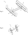
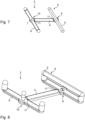
- Belt buckle 2 and its first and second configurations will be described first with reference to Figures 3 to 5 And 6 to 8 , which show it in wide and narrow configuration respectively.
- the belt buckle 2 here comprises a first connecting branch, also called central branch 4, a second branch forming a bridge, also called bridge branch 5, and a third branch forming a tibi, also called a tibi branch 6.
- the bridge branch 5 and the tibi branch 6 are both mechanically secured to the central branch 4 and mounted to be mobile in rotation around the central branch 4.
- the bridge branch 5 here serves as a rigid loop 8 configured to be crossed by the belt ribbon.
- the tibi branch 6 is provided with a tibi member 7 extending at a distance from the central branch 4 and configured to be inserted into at least one mounting/tightening orifice (not shown) provided in the belt ribbon, for example to secure the belt ribbon to the belt buckle and/or to adapt the length of the latter to the size of the wearer of the belt.
- the tibial member 7 here forms a fixed rod provided with a relatively widened head configured to be inserted into the at least one mounting/tightening orifice.
- the belt buckle 2 further comprises here an actuating device provided with a first mechanism 9 configured to allow the pivoting of the bridge branch 5 between a first stable position and a second stable position, and a second mechanism 10 configured to allow the pivoting of the third branch forming the tibi between a first stable position and a second stable position.
- the belt buckle 2 is in the first configuration corresponding to the first belt ribbon width, and the actuating device is configured so that the bridge branch 5 and the tibi branch 6 are in their respective first stable position, in which the latter are for example oriented substantially perpendicular to the central branch 4.
- the belt buckle 2 is in the second configuration corresponding to the second belt ribbon width, and the actuating device is configured so that the bridge branch 5 and the tibi branch 6 are in their respective second stable position, in which the latter are inclined at a determined angle of less than 90° relative to the central branch 4.
- the actuating device is here configured so that in the respective first and second stable positions of the bridge branch 5 and the tibi-forming branch 6, the latter are oriented substantially parallel to each other, passing in particular from a so-called vertical position in the first configuration of the belt buckle 2, to an inclined position, for example with an inclination of between approximately 30° and approximately 75°, in the second configuration of the belt buckle 2.
- central branch 4 comprises support zones 11 arranged at respective ends and which are configured to come into abutment against the bridge branch 5 and the tibi branch 6 respectively in the second respective stable position of the latter ( figures 5 , 7 and 8 ).
- the bridge branch 5 here has a C shape having a main portion 12 and two lateral portions 13 extending on either side of the main portion 12, and a complementary portion 14 extending opposite the main portion 12 and joining the two lateral portions 13, thus forming the rigid loop 8.
- the tibial branch 6 also has a C shape having a main portion 15 and two lateral portions 16 extending on either side of the main portion 15, as well as the tibial member 7 which is mechanically secured to the main portion 15.
- the central branch 4 is provided at its opposite ends where the support zones 11 are arranged, with closing plates 17 and 23.
- Each closing plate 17, 23 here has a generally circular shape.
- the bridge branch 5 and the tibi branch 6 are each provided, on their respective main portion 12, 15 with a wall here circular 18, 19 on which is mounted a respective closing plate 17, 23.
- Each circular wall 18, 19 is provided with a through hole 20, 21 through which is passed a fixing member for securing the bridge branch 5, respectively the tibi branch 6, with the central branch 4.
- the belt buckle 2 comprises a fixing screw 22 which is passed through the through hole 20 formed in the circular wall 18 of the bridge branch 5 and which is fixed in the closing plate 17 at one end of the central branch 4.
- a portion 28 of the stem of the tibial organ 7, opposite its enlarged head, is passed through the through orifice 21 formed in the circular wall 19 of the tibial branch 6 and which is fixed in the closing plate 23 at an opposite end of the central branch 4.
- Each circular wall 18, 19 is further provided with a plurality of housings 24, 33, or grooves, each delimited by an outline 25, 36 and each having a bottom wall 26, 34 in which two recesses 27, 35, or imprints are formed.
- the first mechanism 9 and the second mechanism 10 of the actuating device each comprise a plurality of positioning pins 29, 30 extending projecting from the closing plates 17, 23 of the central branch 4.
- the positioning pins 29, 30 are housed in the respective housings 24 and 33.
- each housing 24, 33 delimits a movement of a respective positioning pin 29, 30.
- the positioning pins 29, 30 are each received, by a respective end, in a respective recess 27, 35.
- each positioning pin 29, 30 may be substantially rounded, in particular semi-circular.
- the first mechanism 9 and the second mechanism 10 of the actuating device each further comprise an adjustment washer 31, 32 housed in the through hole 20 of the circular wall 18 of the bridge branch 4, respectively in the through hole 21 of the circular wall 19 of the tibi branch 5.
- belt buckle 2 has changed from its wide configuration to its narrow configuration, or vice versa.
- the tibial branch 6 is in its first stable position, while the pontet branch 5 is in its second stable position.
- FIG 12 shows the first mechanism 9 which allowed the bridge branch 5 to move from its first stable position to its second stable position, by pivoting the bridge branch 5.
- the positioning pins 29 have moved into the housings 24, with the ends of these positioning pins having passed from one to the other of the recesses 27 in each housing 24.
- the desired width is easily selected by simply pivoting the bridge branch 5 and the tibi branch 6 in one direction or the other respectively to one or the other of the respective first and second stable positions.
- the belt buckle is provided with one or more additional branches, for example an additional bridge branch, or an additional tibi branch.
- the belt buckle may have more than one central branch connecting the bridge and tibi branches.
- the belt buckle can have more than two stable positions so as to be adaptable to more than two belt ribbon widths.
- the belt buckle may be without an adjustment washer.
Landscapes
- Engineering & Computer Science (AREA)
- Textile Engineering (AREA)
- Buckles (AREA)
Claims (12)
- Gürtelschnalle, die an mindestens zwei verschiedene Breiten eines Gürtelbandes (3) anpassbar ist, die einen ersten Verbindungsschenkel (4), einen zweiten Schenkel (5), der einen Bügel (5) bildet, beinhaltet, wobei die Schnalle dadurch gekennzeichnet ist, dass der zweite Schenkel um den ersten Verbindungsschenkel herum drehbeweglich montiert ist, wobei ein dritter Schenkel (6), der eine Spitze bildet und drehbeweglich um den ersten Verbindungsschenkel herum montiert ist, wobei der erste Verbindungsschenkel mechanisch an jedem von dem zweiten Schenkel, der einen Bügel bildet und dem dritten Schenkel, der eine Spitze bildet, festgemacht ist, und eine Betätigungsvorrichtung, die mit einem ersten Mechanismus (9) versehen ist, der konfiguriert ist, um das Schwenken des zweiten Schenkels, der einen Bügel bildet, zwischen einer ersten stabilen Position und einer zweiten stabilen Position zu ermöglichen, und mit einem zweiten Mechanismus (10), der konfiguriert ist, um das Schwenken des dritten Schenkels, der eine Spitze bildet, zwischen einer ersten stabilen Position und einer zweiten stabilen Position zu ermöglichen, wobei die Gürtelschnalle eine erste Konfiguration aufweist, die einer ersten Breite eines Gürtelbandes entspricht, wenn sich der zweite Schenkel, der einen Bügel bildet, und der dritte Schenkel, der eine Spitze bildet, in ihrer jeweiligen ersten stabilen Position befinden, und eine zweite Konfiguration, die einer zweiten Breite eines Gürtelbandes entspricht, wenn sich der zweite Schenkel, der einen Bügel bildet, und der dritte Schenkel, der eine Spitze bildet, in ihrer jeweiligen zweiten stabilen Position befinden.
- Gürtelschnalle nach Anspruch 1, dadurch gekennzeichnet, dass der zweite Schenkel (5), der einen Bügel bildet, als starrer Durchlass dient, der konfiguriert ist, um von dem Gürtelband (3) durchquert zu werden.
- Gürtelschnalle nach einem der Ansprüche 1 und 2, dadurch gekennzeichnet, dass die Betätigungsvorrichtung konfiguriert ist, sodass in den jeweiligen ersten und zweiten stabilen Positionen des zweiten Schenkels (5), der einen Bügel bildet, und des dritten Schenkels (6), der eine Spitze bildet, letztere im Wesentlichen parallel zueinander ausgerichtet sind.
- Gürtelschnalle nach einem der Ansprüche 1 bis 3, dadurch gekennzeichnet, dass die Betätigungsvorrichtung in der jeweiligen ersten stabilen Position des zweiten Schenkels (5), der einen Bügel bildet, und des dritten Schenkels (6), der eine Spitze bildet, letztere im Wesentlichen senkrecht zum ersten Verbindungsschenkel (4) ausgerichtet sind; während in der jeweiligen zweiten stabilen Position des zweiten Schenkels, der einen Bügel bildet, und des dritten Schenkels, der eine Spitze bildet, diese letzteren um einen bestimmten Winkel kleiner als 90° in Bezug auf den ersten Verbindungsschenkel geneigt sind.
- Gürtelschnalle nach einem der Ansprüche 1 bis 4, dadurch gekennzeichnet, dass der erste Mechanismus (9) und der zweite Mechanismus (10) der Betätigungsvorrichtung jeweils eine Vielzahl von Positionierungsstiften (29, 30) beinhalten, die sich aus dem ersten Verbindungsschenkel (4) hervorstehend erstrecken und in einer Vielzahl von Aufnahmen (24, 33) aufgenommen sind, die im zweiten Schenkel (5), der einen Bügel bildet, beziehungsweise im dritten Schenkel (6) der eine Spitze bildet, aufgenommen sind.
- Gürtelschnalle nach Anspruch 5, dadurch gekennzeichnet, dass jede Aufnahme (24, 33) eine Kontur (25, 36), die eine Verschiebung eines jeweiligen Positionierungsstiftes (29, 30) begrenzt, und eine Bodenwand (26, 34) aufweist, in der mindestens zwei voneinander verschiedene Vertiefungen (27, 35) eingearbeitet sind, und vorgesehen sind, um ein Ende des Positionierungsstiftes aufzunehmen, wobei das Zusammenwirken zwischen einem Positionierungsstift und einer der Vertiefungen der einen oder der anderen der ersten und zweiten stabilen Position entspricht.
- Gürtelschnalle nach einem der Ansprüche 1 bis 6, dadurch gekennzeichnet, dass der erste Mechanismus (9) und der zweite Mechanismus (10) der Betätigungsvorrichtung jeweils eine Anpassungsscheibe (31, 32) beinhalten, die im zweiten Schenkel (5), der einen Bügel bildet, beziehungsweise im dritten Schenkel (6), der eine Spitze bildet, aufgenommen ist.
- Gürtelschnalle nach einem der Ansprüche 1 bis 7, dadurch gekennzeichnet, dass der zweite Schenkel (5), der einen Bügel bildet, eine C-Form aufweist, die einen Hauptabschnitt (12) und zwei Seitenabschnitte (13) aufweist, die sich beiderseits des Hauptabschnitts erstrecken, und einen ergänzenden Abschnitt (14), der sich gegenüber dem Hauptabschnitt erstreckt und sich den beiden Seitenabschnitten anschließt.
- Gürtelschnalle nach einem der Ansprüche 1 bis 8, dadurch gekennzeichnet, dass der dritte Schenkel (6), der eine Spitze bildet, eine C-Form aufweist, die einen Hauptabschnitt (15) und zwei Seitenabschnitte (16) aufweist, die sich beiderseits des Hauptabschnitts erstrecken, und ein Spitzenorgan (7), das mechanisch am Hauptabschnitt festgemacht ist.
- Gürtelschnalle nach einem der Ansprüche 1 bis 9, dadurch gekennzeichnet, dass der erste Verbindungsschenkel (4) Stützbereiche (11) beinhaltet, die konfiguriert sind, um sich an jeweils den zweiten Schenkel (5), der einen Bügel bildet, und den dritten Schenkel (6), der eine Spitze bildet, in der jeweiligen zweiten stabilen Position dieser letzteren auf Anschlag anzulegen.
- Gürtel, der eine Gürtelschnalle (2) nach einem der Ansprüche 1 bis 10 und ein Gürtelband (3) beinhaltet, das den zweiten Schenkel (5), der einen Bügel der Gürtelschnalle bildet, durchquert.
- Gürtel nach Anspruch 11, dessen Gürtelband (3) eine erste vorbestimmte Breite (e1) aufweist, und den zweiten Schenkel (5), der einen Bügel der Gürtelschnalle (2) bildet, in seiner ersten Konfiguration durchquert, oder das Gürtelband eine zweite vorbestimmte Breite (e2), kleiner als die erste vorbestimmte Breite, aufweist, und den zweiten Schenkel, der einen Bügel der Gürtelschnalle bildet, in seiner zweiten Konfiguration durchquert.
Applications Claiming Priority (1)
| Application Number | Priority Date | Filing Date | Title |
|---|---|---|---|
| FR2200515A FR3138268B1 (fr) | 2022-01-21 | 2022-01-21 | Boucle de ceinture adaptable à au moins deux largeurs de ruban de ceinture et ceinture comportant une telle boucle |
Publications (2)
| Publication Number | Publication Date |
|---|---|
| EP4215078A1 EP4215078A1 (de) | 2023-07-26 |
| EP4215078B1 true EP4215078B1 (de) | 2024-10-16 |
Family
ID=81927756
Family Applications (1)
| Application Number | Title | Priority Date | Filing Date |
|---|---|---|---|
| EP23152566.8A Active EP4215078B1 (de) | 2022-01-21 | 2023-01-20 | An mindestens zwei gurtbreiten eines gurtes anpassbare gürtelschnalle und gürtel mit einer solchen schnalle |
Country Status (3)
| Country | Link |
|---|---|
| EP (1) | EP4215078B1 (de) |
| CN (1) | CN116919063A (de) |
| FR (1) | FR3138268B1 (de) |
Family Cites Families (3)
| Publication number | Priority date | Publication date | Assignee | Title |
|---|---|---|---|---|
| US673528A (en) * | 1900-07-31 | 1901-05-07 | John C Stulting | Buckle. |
| US3986233A (en) | 1975-09-24 | 1976-10-19 | Swank, Inc. | Transversely adjustable belt buckle |
| FR3104005B1 (fr) | 2019-12-04 | 2021-12-24 | Hermes Sellier | Boucle de ceinture adaptable à au moins deux largeurs de ruban de ceinture et ceinture comportant une telle boucle |
-
2022
- 2022-01-21 FR FR2200515A patent/FR3138268B1/fr active Active
-
2023
- 2023-01-20 EP EP23152566.8A patent/EP4215078B1/de active Active
- 2023-01-20 CN CN202310108341.XA patent/CN116919063A/zh active Pending
Also Published As
| Publication number | Publication date |
|---|---|
| EP4215078A1 (de) | 2023-07-26 |
| CN116919063A (zh) | 2023-10-24 |
| FR3138268B1 (fr) | 2024-07-19 |
| FR3138268A1 (fr) | 2024-02-02 |
Similar Documents
| Publication | Publication Date | Title |
|---|---|---|
| EP1790247B1 (de) | Einrichtung zum Verstellen der Länge eines Armbandes, Armband mit einer solchen Einrichtung, und Uhr ausgerüstet mit einem solchen Armband | |
| EP3412168B1 (de) | Verschluss für armband | |
| EP3769640A1 (de) | Verschluss für uhrenarmband | |
| EP3333643B1 (de) | Befestigungsvorrichtung | |
| EP4062237B1 (de) | Befestigungsvorrichtung für armband | |
| EP0661938B1 (de) | Faltverschluss für armbänder | |
| EP1945893B1 (de) | Eine relativbewegung zwischen zwei starren teilen gestattender mechanismus, der aber mit drehverhinderungsmitteln versehen ist | |
| CH691160A5 (fr) | Fermoir dépliant. | |
| EP3501325B1 (de) | Verschluss für armband | |
| EP4215078B1 (de) | An mindestens zwei gurtbreiten eines gurtes anpassbare gürtelschnalle und gürtel mit einer solchen schnalle | |
| CH694393A5 (fr) | Dispositif de fixation de l'extrémité d'un bracelet au boîtier d'une montre. | |
| CH690894A5 (fr) | Fermoir dépliant, notamment à bouton. | |
| CH705058B1 (fr) | Fermoir. | |
| EP1374716B1 (de) | Armbandverschluss | |
| CH695656A5 (fr) | Maillon réglable en longueur notamment pour bracelet à maillons. | |
| EP1226769B1 (de) | Sportschuh mit in Querrichtung verstellbarer Spannvorrichtung | |
| EP3949790B1 (de) | Gürtelschnalle, die sich an mindestens zwei gürtelbreiten anpassen lässt, und gürtel mit einer solchen schnalle | |
| FR3104005A1 (fr) | Boucle de ceinture adaptable à au moins deux largeurs de ruban de ceinture et ceinture comportant une telle boucle | |
| CH664267A5 (en) | Wrist-watch strap with links slotted for inserts - has resilient fingers which define slots for clipping into grooves around rods paired within outer links | |
| FR2670430A1 (fr) | Dispositif de jonction entre un conduit d'arrivee d'ecrous et un outil de presse. | |
| CH720345A2 (fr) | Dispositif de fixation d'un bracelet | |
| EP4390571A1 (de) | Vorrichtung zur befestigung eines armbandes | |
| EP1304054A1 (de) | Verschluss | |
| CH690519A5 (fr) | Montre-bracelet à cornes munie d'un dispositif de fixation d'un bracelet aux cornes et bracelet notamment pour une telle montre. | |
| EP3333059B1 (de) | Automatisches fahrradpedal |
Legal Events
| Date | Code | Title | Description |
|---|---|---|---|
| PUAI | Public reference made under article 153(3) epc to a published international application that has entered the european phase |
Free format text: ORIGINAL CODE: 0009012 |
|
| STAA | Information on the status of an ep patent application or granted ep patent |
Free format text: STATUS: THE APPLICATION HAS BEEN PUBLISHED |
|
| AK | Designated contracting states |
Kind code of ref document: A1 Designated state(s): AL AT BE BG CH CY CZ DE DK EE ES FI FR GB GR HR HU IE IS IT LI LT LU LV MC ME MK MT NL NO PL PT RO RS SE SI SK SM TR |
|
| STAA | Information on the status of an ep patent application or granted ep patent |
Free format text: STATUS: REQUEST FOR EXAMINATION WAS MADE |
|
| 17P | Request for examination filed |
Effective date: 20231123 |
|
| RBV | Designated contracting states (corrected) |
Designated state(s): AL AT BE BG CH CY CZ DE DK EE ES FI FR GB GR HR HU IE IS IT LI LT LU LV MC ME MK MT NL NO PL PT RO RS SE SI SK SM TR |
|
| GRAP | Despatch of communication of intention to grant a patent |
Free format text: ORIGINAL CODE: EPIDOSNIGR1 |
|
| STAA | Information on the status of an ep patent application or granted ep patent |
Free format text: STATUS: GRANT OF PATENT IS INTENDED |
|
| INTG | Intention to grant announced |
Effective date: 20240606 |
|
| GRAS | Grant fee paid |
Free format text: ORIGINAL CODE: EPIDOSNIGR3 |
|
| GRAA | (expected) grant |
Free format text: ORIGINAL CODE: 0009210 |
|
| STAA | Information on the status of an ep patent application or granted ep patent |
Free format text: STATUS: THE PATENT HAS BEEN GRANTED |
|
| AK | Designated contracting states |
Kind code of ref document: B1 Designated state(s): AL AT BE BG CH CY CZ DE DK EE ES FI FR GB GR HR HU IE IS IT LI LT LU LV MC ME MK MT NL NO PL PT RO RS SE SI SK SM TR |
|
| REG | Reference to a national code |
Ref country code: GB Ref legal event code: FG4D Free format text: NOT ENGLISH |
|
| REG | Reference to a national code |
Ref country code: DE Ref legal event code: R096 Ref document number: 602023000713 Country of ref document: DE Ref country code: CH Ref legal event code: EP |
|
| REG | Reference to a national code |
Ref country code: IE Ref legal event code: FG4D Free format text: LANGUAGE OF EP DOCUMENT: FRENCH |
|
| P01 | Opt-out of the competence of the unified patent court (upc) registered |
Free format text: CASE NUMBER: APP_59009/2024 Effective date: 20241029 |
|
| REG | Reference to a national code |
Ref country code: LT Ref legal event code: MG9D |
|
| REG | Reference to a national code |
Ref country code: NL Ref legal event code: MP Effective date: 20241016 |
|
| REG | Reference to a national code |
Ref country code: AT Ref legal event code: MK05 Ref document number: 1732177 Country of ref document: AT Kind code of ref document: T Effective date: 20241016 |
|
| PG25 | Lapsed in a contracting state [announced via postgrant information from national office to epo] |
Ref country code: NL Free format text: LAPSE BECAUSE OF FAILURE TO SUBMIT A TRANSLATION OF THE DESCRIPTION OR TO PAY THE FEE WITHIN THE PRESCRIBED TIME-LIMIT Effective date: 20241016 |
|
| PG25 | Lapsed in a contracting state [announced via postgrant information from national office to epo] |
Ref country code: NL Free format text: LAPSE BECAUSE OF FAILURE TO SUBMIT A TRANSLATION OF THE DESCRIPTION OR TO PAY THE FEE WITHIN THE PRESCRIBED TIME-LIMIT Effective date: 20241016 |
|
| PG25 | Lapsed in a contracting state [announced via postgrant information from national office to epo] |
Ref country code: IS Free format text: LAPSE BECAUSE OF FAILURE TO SUBMIT A TRANSLATION OF THE DESCRIPTION OR TO PAY THE FEE WITHIN THE PRESCRIBED TIME-LIMIT Effective date: 20250216 Ref country code: HR Free format text: LAPSE BECAUSE OF FAILURE TO SUBMIT A TRANSLATION OF THE DESCRIPTION OR TO PAY THE FEE WITHIN THE PRESCRIBED TIME-LIMIT Effective date: 20241016 Ref country code: PT Free format text: LAPSE BECAUSE OF FAILURE TO SUBMIT A TRANSLATION OF THE DESCRIPTION OR TO PAY THE FEE WITHIN THE PRESCRIBED TIME-LIMIT Effective date: 20250217 |
|
| PGFP | Annual fee paid to national office [announced via postgrant information from national office to epo] |
Ref country code: DE Payment date: 20250124 Year of fee payment: 3 |
|
| PG25 | Lapsed in a contracting state [announced via postgrant information from national office to epo] |
Ref country code: FI Free format text: LAPSE BECAUSE OF FAILURE TO SUBMIT A TRANSLATION OF THE DESCRIPTION OR TO PAY THE FEE WITHIN THE PRESCRIBED TIME-LIMIT Effective date: 20241016 |
|
| PG25 | Lapsed in a contracting state [announced via postgrant information from national office to epo] |
Ref country code: BG Free format text: LAPSE BECAUSE OF FAILURE TO SUBMIT A TRANSLATION OF THE DESCRIPTION OR TO PAY THE FEE WITHIN THE PRESCRIBED TIME-LIMIT Effective date: 20241016 |
|
| PG25 | Lapsed in a contracting state [announced via postgrant information from national office to epo] |
Ref country code: ES Free format text: LAPSE BECAUSE OF FAILURE TO SUBMIT A TRANSLATION OF THE DESCRIPTION OR TO PAY THE FEE WITHIN THE PRESCRIBED TIME-LIMIT Effective date: 20241016 |
|
| PG25 | Lapsed in a contracting state [announced via postgrant information from national office to epo] |
Ref country code: NO Free format text: LAPSE BECAUSE OF FAILURE TO SUBMIT A TRANSLATION OF THE DESCRIPTION OR TO PAY THE FEE WITHIN THE PRESCRIBED TIME-LIMIT Effective date: 20250116 |
|
| PG25 | Lapsed in a contracting state [announced via postgrant information from national office to epo] |
Ref country code: LV Free format text: LAPSE BECAUSE OF FAILURE TO SUBMIT A TRANSLATION OF THE DESCRIPTION OR TO PAY THE FEE WITHIN THE PRESCRIBED TIME-LIMIT Effective date: 20241016 Ref country code: AT Free format text: LAPSE BECAUSE OF FAILURE TO SUBMIT A TRANSLATION OF THE DESCRIPTION OR TO PAY THE FEE WITHIN THE PRESCRIBED TIME-LIMIT Effective date: 20241016 Ref country code: GR Free format text: LAPSE BECAUSE OF FAILURE TO SUBMIT A TRANSLATION OF THE DESCRIPTION OR TO PAY THE FEE WITHIN THE PRESCRIBED TIME-LIMIT Effective date: 20250117 |
|
| PG25 | Lapsed in a contracting state [announced via postgrant information from national office to epo] |
Ref country code: PL Free format text: LAPSE BECAUSE OF FAILURE TO SUBMIT A TRANSLATION OF THE DESCRIPTION OR TO PAY THE FEE WITHIN THE PRESCRIBED TIME-LIMIT Effective date: 20241016 |
|
| PGFP | Annual fee paid to national office [announced via postgrant information from national office to epo] |
Ref country code: FR Payment date: 20250125 Year of fee payment: 3 |
|
| PGFP | Annual fee paid to national office [announced via postgrant information from national office to epo] |
Ref country code: IT Payment date: 20250131 Year of fee payment: 3 |
|
| PG25 | Lapsed in a contracting state [announced via postgrant information from national office to epo] |
Ref country code: RS Free format text: LAPSE BECAUSE OF FAILURE TO SUBMIT A TRANSLATION OF THE DESCRIPTION OR TO PAY THE FEE WITHIN THE PRESCRIBED TIME-LIMIT Effective date: 20250116 |
|
| PG25 | Lapsed in a contracting state [announced via postgrant information from national office to epo] |
Ref country code: SM Free format text: LAPSE BECAUSE OF FAILURE TO SUBMIT A TRANSLATION OF THE DESCRIPTION OR TO PAY THE FEE WITHIN THE PRESCRIBED TIME-LIMIT Effective date: 20241016 |
|
| PG25 | Lapsed in a contracting state [announced via postgrant information from national office to epo] |
Ref country code: DK Free format text: LAPSE BECAUSE OF FAILURE TO SUBMIT A TRANSLATION OF THE DESCRIPTION OR TO PAY THE FEE WITHIN THE PRESCRIBED TIME-LIMIT Effective date: 20241016 |
|
| REG | Reference to a national code |
Ref country code: DE Ref legal event code: R097 Ref document number: 602023000713 Country of ref document: DE |
|
| PG25 | Lapsed in a contracting state [announced via postgrant information from national office to epo] |
Ref country code: EE Free format text: LAPSE BECAUSE OF FAILURE TO SUBMIT A TRANSLATION OF THE DESCRIPTION OR TO PAY THE FEE WITHIN THE PRESCRIBED TIME-LIMIT Effective date: 20241016 |
|
| PG25 | Lapsed in a contracting state [announced via postgrant information from national office to epo] |
Ref country code: RO Free format text: LAPSE BECAUSE OF FAILURE TO SUBMIT A TRANSLATION OF THE DESCRIPTION OR TO PAY THE FEE WITHIN THE PRESCRIBED TIME-LIMIT Effective date: 20241016 |
|
| PG25 | Lapsed in a contracting state [announced via postgrant information from national office to epo] |
Ref country code: SK Free format text: LAPSE BECAUSE OF FAILURE TO SUBMIT A TRANSLATION OF THE DESCRIPTION OR TO PAY THE FEE WITHIN THE PRESCRIBED TIME-LIMIT Effective date: 20241016 |
|
| PG25 | Lapsed in a contracting state [announced via postgrant information from national office to epo] |
Ref country code: CZ Free format text: LAPSE BECAUSE OF FAILURE TO SUBMIT A TRANSLATION OF THE DESCRIPTION OR TO PAY THE FEE WITHIN THE PRESCRIBED TIME-LIMIT Effective date: 20241016 |
|
| PLBE | No opposition filed within time limit |
Free format text: ORIGINAL CODE: 0009261 |
|
| STAA | Information on the status of an ep patent application or granted ep patent |
Free format text: STATUS: NO OPPOSITION FILED WITHIN TIME LIMIT |
|
| PG25 | Lapsed in a contracting state [announced via postgrant information from national office to epo] |
Ref country code: SE Free format text: LAPSE BECAUSE OF FAILURE TO SUBMIT A TRANSLATION OF THE DESCRIPTION OR TO PAY THE FEE WITHIN THE PRESCRIBED TIME-LIMIT Effective date: 20241016 |
|
| PG25 | Lapsed in a contracting state [announced via postgrant information from national office to epo] |
Ref country code: MC Free format text: LAPSE BECAUSE OF FAILURE TO SUBMIT A TRANSLATION OF THE DESCRIPTION OR TO PAY THE FEE WITHIN THE PRESCRIBED TIME-LIMIT Effective date: 20241016 Ref country code: LU Free format text: LAPSE BECAUSE OF NON-PAYMENT OF DUE FEES Effective date: 20250120 |
|
| 26N | No opposition filed |
Effective date: 20250717 |
|
| PG25 | Lapsed in a contracting state [announced via postgrant information from national office to epo] |
Ref country code: BE Free format text: LAPSE BECAUSE OF NON-PAYMENT OF DUE FEES Effective date: 20250131 |
|
| REG | Reference to a national code |
Ref country code: BE Ref legal event code: MM Effective date: 20250131 |
|
| PG25 | Lapsed in a contracting state [announced via postgrant information from national office to epo] |
Ref country code: IE Free format text: LAPSE BECAUSE OF NON-PAYMENT OF DUE FEES Effective date: 20250120 |